ICGOO在线商城 > NTA0505MEC

 Datasheet下载
- 型号: NTA0505MEC
- 制造商: Murata
- 库位|库存: xxxx|xxxx
- 要求:
| 数量阶梯 | 香港交货 | 国内含税 |
| +xxxx | $xxxx | ¥xxxx |
查看当月历史价格
查看今年历史价格
NTA0505MEC产品简介:
ICGOO电子元器件商城为您提供NTA0505MEC由Murata设计生产,在icgoo商城现货销售,并且可以通过原厂、代理商等渠道进行代购。 提供NTA0505MEC价格参考以及MurataNTA0505MEC封装/规格参数等产品信息。 你可以下载NTA0505MEC参考资料、Datasheet数据手册功能说明书, 资料中有NTA0505MEC详细功能的应用电路图电压和使用方法及教程。
| 参数 | 数值 |
| 品牌 | Murata Power Solutions |
| 产品目录 | 电源 |
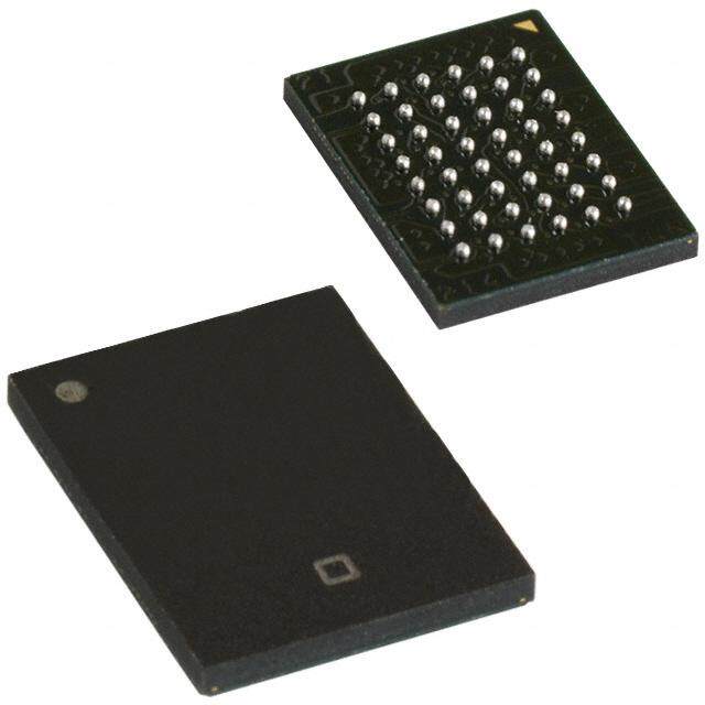
| 描述 | 隔离式DC/DC转换器 1W 5Vin +/-5Vout +/-100mA 80% eff SMT |
| 产品分类 | DC/DC转换器 |
| 产品手册 | |
| 产品图片 |
|
| rohs | RoHS 合规性豁免 |
| 产品系列 | 隔离式DC/DC转换器,Murata Power Solutions NTA0505MEC |
| mouser_ship_limit | 该产品可能需要其他文档才能发货到中国。 |
| 产品型号 | NTA0505MEC |
| 产品 | Isolated |
| 产品种类 | 隔离式DC/DC转换器 |
| 单位重量 | 1.530 g |
| 商标 | Murata Power Solutions |
| 安装风格 | SMD/SMT |
| 封装 | Tube |
| 工厂包装数量 | 25 |
| 绝缘电压 | 1 kV |
| 输入电压—公称值 | 5 V |
| 输入电压范围 | 4.5 V to 5.5 V |
| 输出功率 | 0.5 W |
| 输出电压—通道1 | +/- 5 V |
| 输出电压—通道2 | 5 V |
| 输出电流—通道1 | 100 mA |
| 输出电流—通道2 | 100 mA |
| 输出端数量 | 2 |
| 输出类型 | Isolated |


- 商务部:美国ITC正式对集成电路等产品启动337调查
- 曝三星4nm工艺存在良率问题 高通将骁龙8 Gen1或转产台积电
- 太阳诱电将投资9.5亿元在常州建新厂生产MLCC 预计2023年完工
- 英特尔发布欧洲新工厂建设计划 深化IDM 2.0 战略
- 台积电先进制程称霸业界 有大客户加持明年业绩稳了
- 达到5530亿美元!SIA预计今年全球半导体销售额将创下新高
- 英特尔拟将自动驾驶子公司Mobileye上市 估值或超500亿美元
- 三星加码芯片和SET,合并消费电子和移动部门,撤换高东真等 CEO
- 三星电子宣布重大人事变动 还合并消费电子和移动部门
- 海关总署:前11个月进口集成电路产品价值2.52万亿元 增长14.8%


PDF Datasheet 数据手册内容提取
NTA Series www.murata-ps.com Isolated 1W Dual Output SM DC-DC Converters SELECTION GUIDE Nominal Input Output Output Isolation Input Current at Efficiency MTTF2 Order Code1 Voltage Current Capacitance Voltage Rated Load V V mA mA % pF kHrs NTA0303MC 3.3 ±3.3 ±152 402 75 29 1005 NTA0305MC 3.3 ±5 ±100 388 78 30 399 NTA0309MC 3.3 ±9 ±55 405 75 34 827 NTA0312MC 3.3 ±12 ±42 390 77 40 375 NTA0315MC 3.3 ±15 ±33 392 77 42 206 NTA0503MC 5 ±3.3 ±152 259 77 31 964 FEATURES NTA0505MC 5 ±5 ±100 290 69 33 1697 (cid:132)(cid:3)RoHS compliant NTA0505MEC 5 ±5 ±100 251 80 42 367 NTA0509MC 5 ±9 ±55 267 75 38 682 (cid:132)(cid:3)Efficiency up to 78% NTA0512MC 5 ±12 ±42 260 77 44 343 (cid:132)(cid:3)Wide temperature performance at full NTA0515MC 5 ±15 ±33 256 78 43 188 1 Watt load, –40°C to 85°C NTA1205MC 12 ±5 ±100 121 69 50 559 NTA1209MC 12 ±9 ±55 113 74 72 375 (cid:132)(cid:3)UL 94V-0 Package material NTA1212MC 12 ±12 ±42 111 75 89 243 (cid:132)(cid:3)Footprint over pins 1.64cm2 NTA1215MC 12 ±15 ±33 110 76 100 154 (cid:132)(cid:3)Lead frame technology INPUT CHARACTERISTICS (cid:132)(cid:3)3.3V, 5V & 12V Input Parameter Conditions Min. Typ. Max. Units (cid:132)(cid:3)3.3V, 5V, 9V, 12V & 15V Output Continuous operation, 3V input types 2.97 3.3 3.63 Voltage range Continuous operation, 5V input types 4.5 5 5.5 V (cid:132)(cid:3)Internal SMD construction Continuous operation, 12V input types 10.8 12 13.2 (cid:132)(cid:3)Toroidal magnetics Reflected ripple current 41 50 mA p-p (cid:132)(cid:3)1kVDC Isolation ‘Hi Pot Test’ ISOLATION CHARACTERISTICS (cid:132)(cid:3)MTTF up to 2.1 Million hours Parameter Conditions Min. Typ. Max. Units (cid:132)(cid:3)Power density 1.36W/cm3 Isolation voltage Flash tested for 1 second 1000 VDC Resistance Viso= 1000VDC 10 GΩ (cid:132)(cid:3)No heatsink required (cid:132)(cid:3)Custom solutions available GENERAL CHARACTERISTICS Parameter Conditions Min. Typ. Max. Units (cid:132)(cid:3)Multi-layer ceramic capacitors 0312MC, 0315MC 100 Switching frequency 0303MC, 0305MC, 0503MC, 0505MEC 110 kHz PRODUCT OVERVIEW All other variants 115 The NTA series of miniature surface mounted DC-DC Converters employ leadframe ABSOLUTE MAXIMUM RATINGS technology and transfer moulding techniques Internal power dissipation 700mW to bring all of the benefits of IC style Input voltage VIN, NTA03 types 5.5V packaging to hybrid circuitry. Co-planarity of the Input voltage VIN, NTA05 types 7V lead positions is based upon IEC 191-6:1990. The Input voltage VIN, NTA12 types 15V devices are suitable for all applications where high volume production is envisaged. 1. If components are required in tape and reel format suffix order code with -R, e.g. NTA0505MC-R. 2. Calculated using MIL-HDBK-217F with nominal input voltage at full load. For full details go to www.murata-ps.com/rohs All specifications typical at TA=25°C, nominal input voltage and rated output current unless otherwise specified. www.murata-ps.com/support KDC_NTA.I09 Page 1 of 8
NTA Series Isolated 1W Dual Output SM DC-DC Converters OUTPUT CHARACTERISTICS Parameter Conditions Min. Typ. Max. Units Rated Power TA=-40°C to 85°C 1.0 W Voltage Set Point Accuracy See tolerance envelope Line regulation High VIN to low VIN 1.0 1.2 %/% 10% load to rated load, 0303MC & 0503MC 10 15 10% load to rated load, 5V output types 10 12 10% load to rated load, 0309MC 9.0 10 Load Regulation1 10% load to rated load, 0509MC & 1209MC 6.5 8.0 % 10% load to rated load, 0312MC & 0315MC 11 14 10% load to rated load, 0512MC & 1212MC 6.0 8.5 10% load to rated load, 0515MC & 1215MC 6.0 7.0 BW=DC to 20MHz, 3.3V output types, NTA0305MC & NTA0505MEC 40 80 BW=DC to 20MHz, all other 5V output types 50 100 Ripple and Noise BW=DC to 20MHz, 9V output types 35 80 mV p-p BW=DC to 20MHz, 12V output types 50 110 BW=DC to 20MHz, 15V output types 65 110 TEMPERATURE CHARACTERISTICS Parameter Conditions Min. Typ. Max. Units Specification All output types -40 85 Storage -55 125 0305MC, 0505MEC, 0312MC, 0315MC 19 °C Case temperature rise above 0303MC, 0309MC, 0503MC 25 ambient 0505MC, 1205MC 46 All other variants 35 Cooling Free air convection 1. 12V input types have typically 3% less load regulation change. www.murata-ps.com/support KDC_NTA.I09 Page 2 of 8
NTA Series Isolated 1W Dual Output SM DC-DC Converters TECHNICAL NOTES ISOLATION VOLTAGE ‘Hi Pot Test’, ‘Flash Tested’, ‘Withstand Voltage’, ‘Proof Voltage’, ‘Dielectric Withstand Voltage’ & ‘Isolation Test Voltage’ are all terms that relate to the same thing, a test voltage, applied for a specified time, across a component designed to provide electrical isolation, to verify the integrity of that isolation. Murata Power Solutions NTA series of DC-DC converters are all 100% production tested at their stated isolation voltage. This is 1kVDC for 1 second. A question commonly asked is, “What is the continuous voltage that can be applied across the part in normal operation?” For a part holding no specific agency approvals, such as the NTA series, both input and output should normally be maintained within SELV limits i.e. less than 42.4V peak, or 60VDC. The isolation test voltage represents a measure of immunity to transient voltages and the part should never be used as an element of a safety isolation system. The part could be expected to function correctly with several hundred volts offset applied continuously across the isolation barrier; but then the circuitry on both sides of the barrier must be regarded as operating at an unsafe voltage and further isolation/insulation systems must form a barrier between these circuits and any user-accessible circuitry according to safety standard requirements. REPEATED HIGH-VOLTAGE ISOLATION TESTING It is well known that repeated high-voltage isolation testing of a barrier component can actually degrade isolation capability, to a lesser or greater degree depending on materials, construction and environment. The NTA series has toroidal isolation transformers, with no additional insulation between primary and secondary windings of enamelled wire. While parts can be expected to withstand several times the stated test voltage, the isolation capability does depend on the wire insulation. Any material, including this enamel (typically polyurethane) is susceptible to eventual chemical degradation when subject to very high applied voltages thus implying that the number of tests should be strictly limited. We therefore strongly advise against repeated high voltage isolation testing, but if it is absolutely required, that the voltage be reduced by 20% from specified test voltage. This consideration equally applies to agency recognised parts rated for better than functional isolation where the wire enamel insulation is always supplemented by a further insulation system of physical spacing or barriers. RoHS COMPLIANCE, MSL AND PSL INFORMATION This series is compatible with RoHS soldering systems and is also backward compatible with Sn/Pb soldering systems. The NTA series has a process, moisture, and reflow sensitivity classification of MSL1 PSL R7F as defined in J-STD-020 and J-STD-075. This translates to: MSL1 = unlimited floor life, PSL R7F = Peak reflow temperature 245°C with a limitation on the time above liquidus (217°C) which for this series is 60sec max. The pin termination finish on this product series is Gold with a plating thickness of 0.05 microns minimum. For further information please visit www.murata-ps.com/rohs PART NUMBER STRUCTURE NTA XX XX M C -R Series name Packaging code Input voltage RoHS compliant Output voltage Package type S - SIP D - DIP M - Surface mount www.murata-ps.com/support KDC_NTA.I09 Page 3 of 8
NTA Series Isolated 1W Dual Output SM DC-DC Converters APPLICATION NOTES Minimum load The minimum load to meet datasheet specification is 10% of the full rated load across the specified input voltage range. Lower than 10% minimum loading will result in an increase in output voltage, which may rise to typically double the specified output voltage if the output load falls to less than 5%. Capacitive loading and start up Typical start up times for this series, with a typical input voltage rise time of 2.2μs and output capacitance of 10μF, are shown in the table below. The product series will start into a capacitance of 47μF with an increased start time, however, the maximum recommended output capacitance is 10μF. Typical Start-Up Wave Form Start-up time Start-up time μs μs NTA0303MC 1630 NTA0509MC 6850 NTA0305MC 1359 NTA0512MC 11560 NTA0309MC 3435 NTA0515MC 15640 NTA0312MC 6590 NTA1205MC 1154 NTA0315MC 25340 NTA1209MC 4050 NTA0503MC 1599 NTA1212MC 7995 NTA0505MC 2185 NTA1215MC 11200 NTA0505MEC 1395 Ripple & Noise Characterisation Method Ripple and noise measurements are performed with the following test configuration. C1 1μF X7R m ultilayer ceramic capacitor, voltage rating to be a minimum of 3 times the output voltage of the DC-DC converter 10μF tantalum capacitor, voltage rating to be a minimum of 1.5 times the output voltage of the DC-DC converter with an ESR of less C2 than 100mΩ at 100 kHz C3 100nF multilayer ceramic capacitor, general purpose R1 450Ω resistor, carbon film, ±1% tolerance R2 50Ω BNC termination T1 3T of the coax cable through a ferrite toroid RLOAD Resistive load to the maximum power rating of the DC-DC converter. Connections should be made via twisted wires Measured values are multiplied by 10 to obtain the specified values. Differential Mode Noise Test Schematic DC/DC Converter OSCILLOSCOPE C1 C2 C3 R1 T1 R2 + + Y INPUT SUPPLY Input Output - - R LOAD www.murata-ps.com/support KDC_NTA.I09 Page 4 of 8
NTA Series Isolated 1W Dual Output SM DC-DC Converters APPLICATION NOTES (continued) Output Ripple Reduction By using the values of inductance and capacitance stated, the output ripple at the rated load is lowered to 5mV p-p max. Component selection Capacitor: It is required that the ESR (Equivalent Series Resistance) should be as low as possible, ceramic types are recommended. The voltage rating should be at least twice (except for 15V output), the rated output voltage of the DC-DC converter. Inductor: The rated current of the inductor should not be less than that of the output of the DC-DC converter. At the rated current, the DC resistance of the inductor should be such that the voltage drop across the inductor is <2% of the rated voltage of the DC-DC converter. The SRF (Self Resonant Frequency) should be >20MHz. +VOUT L DC C Load Power OV Source DC C Load -VOUT L Inductor Capacitor L, μH SMD Through Hole C, μF NTA0303MC 10 82103C 11R103C 4.7 NTA0305MC 22 82223C 11R223C 2.2 NTA0309MC 22 82223C 11R223C 2.2 NTA0312MC 22 82223C 11R223C 1 NTA0315MC 22 82223C 11R223C 1 NTA0503MC 10 82103C 11R103C 4.7 NTA0505MC 10 82103C 11R103C 4.7 NTA0505MEC 10 82103C 11R103C 4.7 NTA0509MC 22 82223C 11R223C 2.2 NTA0512MC 22 82473C 11R473C 1 NTA0515MC 22 82474C 11R474C 1 NTA1205MC 10 82103C 11R103C 4.7 NTA1209MC 22 82223C 11R223C 2.2 NTA1212MC 22 82223C 11R223C 1 NTA1215MC 22 82223C 11R223C 1 www.murata-ps.com/support KDC_NTA.I09 Page 5 of 8
NTA Series Isolated 1W Dual Output SM DC-DC Converters TOLERANCE ENVELOPES The voltage tolerance envelope shows typical load regulation characteristics for this product series. The tolerance envelope is the maximum output voltage variation due to changes in output loading. 3.3Vout All other output voltage 9% 10% Output Voltage -17%% Typical Load Line 1-7%% Output Voltage 50%% Typical Load Line --227.5..55%%% -15% 10 25 50 75 100 10 25 50 75 100 Output Load Current (%) Output Load Current (%) TEMPERATURE DERATING GRAPH 1.5 W) 1.0 r ( e w o P ut 0.5 Safe Operating Area p ut O 0 -40 0 50 100 150 Ambient T ) www.murata-ps.com/support KDC_NTA.I09 Page 6 of 8
NTA Series Isolated 1W Dual Output SM DC-DC Converters PACKAGE SPECIFICATIONS MECHANICAL DIMENSIONS PIN CONNECTIONS 15.24 [0.600] Pin Function 10.16 [0.400] 1 -VIN DETAIL A 3 +VIN 18 10 5 NA REFERENCE 0.50 [0.020] 11.20 [0.441] PLANE 7 OV 10.40 0.409 7.70 [0.303] NTAXXXXMC P 9 -VOUT XYYWW 10 NA 1 9 x10 PINS 1.50 [0.059] ±5.0° 12 +VOUT 2.54 [0.100] 1.20 [0.047] 14 NA 0.2 [0.008] S x10 PINS 16 NA 0.2 [0.008] S 00..7455 [00..003108] 18 NA NA - Not available for electrical connection. (1.875 [0.074] MAX) 2.79 [0.110] MAX 2.10 [0.083] ( 56..9650) [( 00..223640)] ( 65..3855) [( 00..225300)] S 00..3200 [00..001028] x10 PINS 0.25 [0.010] SEATING PLANE 0.10 0.004 0.1 [0.004] S DETAIL A All dimensions in mm (inches), Controlling dimension is mm. Tolerances (unless otherwise stated) ±0.25 (0.010). Weight: 1.53g RECOMMENDED FOOTPRINT DETAILS TUBE OUTLINE DIMENSIONS 10.16 [0.400] 0.60±0.15 (0.024±0.006) 2.10 (0.083) x10 PLACES 2.00 [0.079] 9.70 [0.382] 14.35 (0.565) 9.40 (0.370) x10 PLACES 1.00 [0.039] MIN 6.70 (0.264) 2.54 [0.100] Unless otherwise stated all dimensions in mm±0.5 (inches ±0.02). Tube length : 475±2.0 (18.70±0.07). Tube Quantity : 25 www.murata-ps.com/support KDC_NTA.I09 Page 7 of 8
NTA Series Isolated 1W Dual Output SM DC-DC Converters TAPE & REEL SPECIFICATIONS REEL OUTLINE DIMENSIONS TAPE OUTLINE DIMENSIONS 330 (12.99) MAX 15.75 (0.62) 0.60 (0.02) MAX 100 Ø (3.94) MIN +0.10 (+0.004) Ø1.50 (0.06) -0.00 (-0.00) G N REELI 16.00 (0.63) N HUB SECTION) Ø 1(03..5010±±00..02059) (20..0008 ) DIRECTION OF U AT +2.00 (0.08)24.40 (0.96)(-0.00 (0.00) 30.40 (1.20 ) MAX (40..0106 ) (101..4660) 1.75(0.07) 6.60 (0.26) 11.50 (0.45) 24.00±0.30 (0.94±0.04) REEL PACKAGING DETAILS XYYWWNTA0505MC XYYWWNTA0505MC XYYWWNTA0505MC TRAILER SECTION GOODS ENCLOSURE CARRIER TAPE START 160 (6.30) MIN SECTION 100 (3.94) MIN Product Orientation Pin 1, located nearest to LEADER SECTION carrier drive sprocket. 400 (15.75) MIN Reel Quantity : 500 This product is subject to the following operating requirements and the Life and Safety Critical Application Sales Policy: Refer to: http://www.murata-ps.com/requirements/ Murata Power Solutions, Inc. makes no representation that the use of its products in the circuits described herein, or the use of other technical information contained herein, will not infringe upon existing or future patent rights. The descriptions contained herein do not imply the granting of licenses to make, use, or sell equipment constructed in accordance therewith. Specifications are subject to change without notice. © 2019 Murata Power Solutions, Inc. www.murata-ps.com/support KDC_NTA.I09 Page 8 of 8
Mouser Electronics Authorized Distributor Click to View Pricing, Inventory, Delivery & Lifecycle Information: M urata: NTA1205MC NTA0505MC NTA0515MC NTA1215MC NTA0303MC NTA0303MC-R NTA0305MC NTA0305MC-R NTA0309MC NTA0309MC-R NTA0312MC-R NTA0315MC-R NTA0503MC NTA0503MC-R NTA0505MC-R NTA0505MEC NTA0505MEC-R NTA0509MC NTA0509MC-R NTA0512MC-R NTA0515MC-R NTA1205MC-R NTA1209MC NTA1209MC-R NTA1212MC-R NTA1215MC-R NTA0512MC NTA1212MC NTA0312MC NTA0315MC