ICGOO在线商城 > 开发板,套件,编程器 > 评估板 - 嵌入式 - MCU,DSP > MSP-EXP430G2
 Datasheet下载
- 型号: MSP-EXP430G2
- 制造商: Texas Instruments
- 库位|库存: xxxx|xxxx
- 要求:
| 数量阶梯 | 香港交货 | 国内含税 |
| +xxxx | $xxxx | ¥xxxx |
查看当月历史价格
查看今年历史价格
MSP-EXP430G2产品简介:
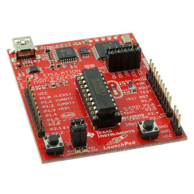
ICGOO电子元器件商城为您提供MSP-EXP430G2由Texas Instruments设计生产,在icgoo商城现货销售,并且可以通过原厂、代理商等渠道进行代购。 MSP-EXP430G2价格参考。Texas InstrumentsMSP-EXP430G2封装/规格:评估板 - 嵌入式 - MCU,DSP, MSP430G2XX LaunchPad™ MSP430G2 MCU 16-Bit Embedded Evaluation Board。您可以下载MSP-EXP430G2参考资料、Datasheet数据手册功能说明书,资料中有MSP-EXP430G2 详细功能的应用电路图电压和使用方法及教程。
Texas Instruments(德州仪器)的MSP-EXP430G2是一款专为嵌入式系统设计的评估板,主要用于评估和开发基于MSP430G2系列微控制器(MCU)的应用。这款评估板特别适用于低功耗、高性价比的嵌入式应用场景,广泛应用于工业、消费电子、医疗设备等领域。

 应用场景:

1. 低功耗应用:
   MSP-EXP430G2的核心优势在于其极低的功耗特性,适合需要长时间运行且对电池寿命要求较高的应用。例如,无线传感器网络中的节点、环境监测设备、智能表计等,都可以通过该评估板进行开发和测试。

2. 便携式设备:
   由于其低功耗和小尺寸的特点,MSP-EXP430G2非常适合用于便携式设备的设计。比如,手持式测量工具、便携式健康监测设备(如心率监测器、血糖仪等),这些设备通常需要在有限的电源条件下长时间工作,而MSP430G2能够很好地满足这一需求。

3. 智能家居与物联网(IoT):
   在智能家居和物联网领域,MSP-EXP430G2可以用于开发各种智能终端设备。例如,智能插座、智能灯控、温度控制器等。这些设备通常需要具备低功耗、高效处理能力和易于集成的特点,MSP430G2正好符合这些要求。

4. 工业自动化:
   在工业自动化领域,MSP-EXP430G2可以用于开发各种传感器接口、数据采集系统和控制单元。例如,工厂中的温度、湿度、压力等传感器的数据采集与处理,以及简单的闭环控制系统。其低功耗特性和丰富的外设接口使其成为工业环境中理想的解决方案。

5. 教育与科研:
   MSP-EXP430G2还广泛应用于高校和科研机构的教学和实验中。它为学生和研究人员提供了一个低成本、易上手的平台,帮助他们学习嵌入式系统开发、低功耗编程以及硬件设计等知识。

6. 可穿戴设备:
   随着可穿戴设备市场的快速发展,MSP-EXP430G2也成为了这类产品开发的理想选择。例如,健身追踪器、智能手表等设备可以通过该评估板进行原型设计和功能验证。

总之,MSP-EXP430G2评估板凭借其低功耗、高性价比和丰富的外设资源,成为嵌入式系统开发中不可或缺的工具,适用于多种应用场景。
| 参数 | 数值 |
| 产品目录 | 编程器,开发系统嵌入式解决方案 |
| 描述 | LAUNCHPAD DEV BRD FOR MSP430G2XX开发板和工具包 - MSP430 MSP430 Value Line LaunchPad Dev Kit |
| 产品分类 | 评估板 - 嵌入式 - MCU, DSP工程工具 |
| 品牌 | Texas Instruments |
| 产品手册 | http://focus.ti.com/docs/toolsw/folders/print/msp-exp430g2.html |
| 产品图片 |
|
| rohs | 符合RoHS含铅 / 不受限制有害物质指令(RoHS)规范要求限制 |
| 产品系列 | 嵌入式开发工具,嵌入式处理器开发套件,开发板和工具包 - MSP430,Texas Instruments MSP-EXP430G2MSP430G2 |
| 数据手册 | http://www.ti.com/lit/pdf/slas191http://www.ti.com/lit/pdf/slay017http://www.ti.com/lit/pdf/slac432 |
| 产品型号 | MSP-EXP430G2 |
| 产品 | Development Kits |
| 产品培训模块 | http://www.digikey.cn/PTM/IndividualPTM.page?site=cn&lang=zhs&ptm=24872http://www.digikey.cn/PTM/IndividualPTM.page?site=cn&lang=zhs&ptm=25404http://www.digikey.cn/PTM/IndividualPTM.page?site=cn&lang=zhs&ptm=25523http://www.digikey.cn/PTM/IndividualPTM.page?site=cn&lang=zhs&ptm=25524http://www.digikey.cn/PTM/IndividualPTM.page?site=cn&lang=zhs&ptm=25537http://www.digikey.cn/PTM/IndividualPTM.page?site=cn&lang=zhs&ptm=25788http://www.digikey.cn/PTM/IndividualPTM.page?site=cn&lang=zhs&ptm=25872http://www.digikey.cn/PTM/IndividualPTM.page?site=cn&lang=zhs&ptm=25882http://www.digikey.cn/PTM/IndividualPTM.page?site=cn&lang=zhs&ptm=25885http://www.digikey.cn/PTM/IndividualPTM.page?site=cn&lang=zhs&ptm=26015http://www.digikey.cn/PTM/IndividualPTM.page?site=cn&lang=zhs&ptm=26006http://www.digikey.cn/PTM/IndividualPTM.page?site=cn&lang=zhs&ptm=30656 |
| 产品目录页面 | |
| 产品种类 | 开发板和工具包 - MSP430 |
| 其它名称 | 296-27570 |
| 内容 | 板,电缆,配件 |
| 制造商产品页 | http://www.ti.com/general/docs/suppproductinfo.tsp?distId=10&orderablePartNumber=MSP-EXP430G2 |
| 商标 | Texas Instruments |
| 安装类型 | 插口 |
| 工具用于评估 | MSP430G2xx, MSP430F20xx |
| 工厂包装数量 | 1 |
| 平台 | LaunchPad |
| 接口类型 | USB |
| 描述/功能 | The MSP-EXP430G2 low-cost experimenter board called LaunchPad is a complete development solution |
| 操作系统 | - |
| 数据总线宽度 | 16 bit |
| 板类型 | 评估平台 |
| 标准包装 | 1 |
| 核心 | MPS430 |
| 核心处理器 | - |
| 特色产品 | http://www.digikey.com/cn/zh/ph/texas-instruments/MSP-EXP430G2.htmlhttp://www.digikey.com/product-highlights/cn/zh/pervasive-displays-epd-extension-kit/4198 |
| 相关产品 | /product-detail/zh/MSP430G2211IN14/296-25829-5-ND/2237184/product-detail/zh/MSP430G2231IN14/296-25832-5-ND/2237187/product-detail/zh/430BOOST-SENSE1/296-28358-ND/2623270/product-detail/zh/430BOOST-CC110L/296-30144-ND/2812673 |
| 类型 | MCU 16-位 |
| 视频文件 | http://www.digikey.cn/classic/video.aspx?PlayerID=1364138032001&width=640&height=455&videoID=1102983713001http://www.digikey.cn/classic/video.aspx?PlayerID=1364138032001&width=640&height=505&videoID=3819279748001 |
| 配套使用产品/相关产品 | MSP430G2XX |


- 商务部:美国ITC正式对集成电路等产品启动337调查
- 曝三星4nm工艺存在良率问题 高通将骁龙8 Gen1或转产台积电
- 太阳诱电将投资9.5亿元在常州建新厂生产MLCC 预计2023年完工
- 英特尔发布欧洲新工厂建设计划 深化IDM 2.0 战略
- 台积电先进制程称霸业界 有大客户加持明年业绩稳了
- 达到5530亿美元!SIA预计今年全球半导体销售额将创下新高
- 英特尔拟将自动驾驶子公司Mobileye上市 估值或超500亿美元
- 三星加码芯片和SET,合并消费电子和移动部门,撤换高东真等 CEO
- 三星电子宣布重大人事变动 还合并消费电子和移动部门
- 海关总署:前11个月进口集成电路产品价值2.52万亿元 增长14.8%


PDF Datasheet 数据手册内容提取
User's Guide SLAU318G–July2010–RevisedMarch2016 MSP-EXP430G2 LaunchPad™ Development Kit The MSP-EXP430G2 LaunchPad development kit is an inexpensive and simple development kit for the MSP430G2xx Value Line series of microcontrollers. It is an easy way to start developing on the MSP430 MCUs with on-board emulation for programming and debugging as well as buttons and LEDs for a simple userinterface. Contents 1 Preface:ReadThisFirst.................................................................................................... 2 2 MSP-EXP430G2LaunchPad™DevelopmentKitOverview........................................................... 2 3 Installation.................................................................................................................... 5 4 GettingStartedWithMSP-EXP430G2LaunchPad™DevelopmentKit.............................................. 6 5 DevelopanApplicationWiththeMSP-EXP430G2LaunchPad™DevelopmentKit................................ 7 6 MSP-EXP430G2Hardware............................................................................................... 12 7 SuggestedReading........................................................................................................ 23 8 FrequentlyAskedQuestions(FAQ)...................................................................................... 23 ListofFigures 1 MSP-EXP430G2LaunchPadDevelopmentKitOverview.............................................................. 3 2 InsertDeviceIntoTargetSocket.......................................................................................... 7 3 CodeComposerStudio™v4inDebuggingMode...................................................................... 8 4 MSP-EXP430G2LaunchPadDevelopmentKitWithAttachedeZ430-RF2500TargetBoard..................... 9 5 DevicePinout............................................................................................................... 12 6 Schematics,MSP-EXP430G2Emulator(1of2),Revision1.4...................................................... 13 7 Schematics,MSP-EXP430G2Emulator(2of2),Revision1.4...................................................... 14 8 Schematics,MSP-EXP430G2TargetSocket,Revision1.4.......................................................... 15 9 Schematics,MSP-EXP430G2Emulator(1of2),Revision1.5...................................................... 16 10 Schematics,MSP-EXP430G2Emulator(2of2),Revision1.5...................................................... 17 11 Schematics,MSP-EXP430G2TargetSocket,Revision1.5.......................................................... 18 12 Layout,MSP-EXP430G2TopLayer..................................................................................... 19 13 Layout,MSP-EXP430G2BottomLayer................................................................................. 20 14 Layout,MSP-EXP430G2Silkscreen..................................................................................... 21 ListofTables 1 JumperConnectionJ3BetweenEmulatorandTarget................................................................. 8 2 eZ430™DebuggingInterface.............................................................................................. 9 3 Supported Devices......................................................................................................... 10 4 FeaturesSupportedbyOn-BoardEmulator............................................................................ 12 5 BillofMaterials............................................................................................................. 22 Trademarks MSP430,E2E,CodeComposerStudio,LaunchPad,BoosterPack,eZ430aretrademarksofTexas Instruments. IAREmbeddedWorkbenchisatrademarkofIARSystems. Allothertrademarksarethepropertyoftheirrespectiveowners. SLAU318G–July2010–RevisedMarch2016 MSP-EXP430G2LaunchPad™DevelopmentKit 1 SubmitDocumentationFeedback Copyright©2010–2016,TexasInstrumentsIncorporated
Preface:ReadThisFirst www.ti.com 1 Preface: Read This First 1.1 If You Need Assistance Ifyouhaveanyfeedbackorquestions,supportforthe MSP430™MCUsandtheMSP-EXP430G2is providedbytheTIProductInformationCenter(PIC)andtheTI E2E™Forum.Contactinformationforthe PICcanbefoundontheTIwebsite.Additionaldevice-specificinformationcanbefoundonthe. 1.2 Related Documentation From TI TheprimarysourcesofMSP430informationarethedevice-specificdatasheetsanduser'sguides availableatthewebsiteforMSP430MCUs. MSP430MCUuser'sguides,applicationreports,softwareexamplesandotherMSP430MCUuser's guidescanbefoundattheTechDocssection.The CodeComposerStudio™v6.1forMSP430User's Guide(SLAU157)includesdetailedinformationonsettingupaprojectandusingCodeComposerStudio (CCS)fortheMSP430microcontroller. InformationaboutMSPdebugsolutions,supportedIDEs,debugprobes,andtargetdevicescanbefound intheMSPDebuggersUser'sGuide(SLAU647). InformationspecifictotheMSP-EXP430G2 LaunchPad™developmentkit,alloftheavailableIDEs, softwarelibraries,andexamplescanbefoundintheTechnicalDocumentsandRelatedProductssections oftheMSP-EXP430G2page. 2 MSP-EXP430G2 LaunchPad™ Development Kit Overview 2.1 Overview Rapidprototypingissimplifiedbythe20-pin BoosterPack™plug-inmoduleheaderswhichsupportawide rangeofavailableBoosterPackplug-inmodules.Youcanquicklyaddfeatureslikewirelessconnectivity, graphicaldisplays,environmentalsensing,andmuchmore.YoucaneitherdesignyourownBoosterPack plug-inmoduleorchooseamongmanyalreadyavailablefromTIandthird-partydevelopers. TheLaunchPaddevelopmentkitfeaturesanintegratedDIPtargetsocketthatsupportsupto20pins, allowingMSP430ValueLinedevicestobepluggedintotheLaunchPaddevelopmentkit.TheMSP- EXP430G2LaunchPaddevelopmentkitcomeswithanMSP430G2553MCUbydefault.The MSP430G2553MCUhasthemostmemoryavailableofthecompatibleValueLinedevices. TheMSP430G255316-bitMCUhas16KBofflash,512bytesofRAM,upto16-MHzCPUspeed,a10-bit ADC,capacitive-touchenabledI/Os,universalserialcommunicationinterface,andmore – plentytoget youstartedinyourdevelopment. Freesoftwaredevelopmenttoolsarealsoavailable:TI'sEclipse-basedCodeComposerStudio™IDE (CCS),IAREmbeddedWorkbench™IDE(IAR),andthecommunity-drivenEnergiaopensourcecode editor.MoreinformationabouttheLaunchPaddevelopmentkit,includingdocumentationanddesignfiles, canbefoundonthetoolpageathttp://www.ti.com/tool/msp-exp430g2. 2.2 Features MSP-EXP430G2LaunchPaddevelopmentkitfeatures: • USBdebuggingandprogramminginterfacefeaturingadriverlessinstallationandapplicationUART serialcommunicationwithupto9600Baud • SupportsMSP430G2xx2,MSP430G2xx3,andMSP430F20xxdevicesinPDIP14orPDIP20packages (seeSection5.7foracompletelistofsupporteddevices) • Twogeneral-purposedigitalI/OpinsconnectedtogreenandredLEDsforvisualfeedback • Twopushbuttonforuserfeedbackanddevicereset • Easilyaccessibledevicepinsfordebuggingpurposesorassocketforaddingcustomizedextension boards • High-quality20-pinDIPsocketforaneasyplug-inorremovalofthetargetdevice 2 MSP-EXP430G2LaunchPad™DevelopmentKit SLAU318G–July2010–RevisedMarch2016 SubmitDocumentationFeedback Copyright©2010–2016,TexasInstrumentsIncorporated
www.ti.com MSP-EXP430G2LaunchPad™DevelopmentKitOverview Figure1. MSP-EXP430G2LaunchPadDevelopmentKitOverview SLAU318G–July2010–RevisedMarch2016 MSP-EXP430G2LaunchPad™DevelopmentKit 3 SubmitDocumentationFeedback Copyright©2010–2016,TexasInstrumentsIncorporated
MSP-EXP430G2LaunchPad™DevelopmentKitOverview www.ti.com 2.3 Kit Contents TheMSP-EXP430G2developmentkitincludesthefollowinghardware: • LaunchPademulatorsocketboard(MSP-EXP430G2) • MiniUSB-Bcable,0.5m • TwoMSP430flash-basedMCUs – MSP430G2553:Low-power16-bitMSP430microcontrollerwithan8-channel10-bitADC,on-chip comparator,touch-senseenabledI/Os,universalserialcommunicationinterface,16kBflash memory,and512bytesofRAM(preloadedwithasampleprogram) – MSP430G2452:Low-power16-bitMSP430microcontrollerwithan8-channel10-bitADC,on-chip comparator,touch-senseenabledI/Os,universalserialinterface,8kBflashmemory,and256bytes ofSRAM • Two10-pinPCBconnectorsfemale • 32.768-kHzclockcrystalfromMicroCrystal(http://www.microcrystal.com) • Quickstartguide • TwoLaunchPaddevelopmentkitstickers 2.4 Revisions ThefirstproductionrevisionoftheLaunchPaddevelopmentkitin2010was1.3.In2012theLaunchPad boardrevisionchangedfrom1.4to1.5toalignwiththenewreleaseofValueLinedevices.The differencesintheschematicandthekitcontentsare: • LayoutandSchematic: – Voltagefeedbackintheemulatorchangedtoincreasestartupstability(Rev1.3toRev1.4) – RearrangedjumperJ3tosupporttwoUARTconfigurations:vertical(SWUART),horizontal(HW UART) – VCContheconnectorJ4cannowbedisconnectedfromtheemulatorVCCbyJ3 – PullupresistorR34andcapacitorC24onP1.3removedtoreducethecurrentconsumption – PresolderedmaleheadersJ1andJ2 4 MSP-EXP430G2LaunchPad™DevelopmentKit SLAU318G–July2010–RevisedMarch2016 SubmitDocumentationFeedback Copyright©2010–2016,TexasInstrumentsIncorporated
www.ti.com Installation 3 Installation InstallationoftheMSP-EXP430G2LaunchPaddevelopmentkitconsistsofthreeeasysteps: 1. Downloadtherequiredsoftware. 2. InstalltheselectedIDE. 3. ConnecttheLaunchPadtothePC. ThentheLaunchPaddevelopmentkitisreadytodevelopapplicationsortousethepre-programmed demoapplication. 3.1 Download the Required Software DifferentdevelopmentsoftwaretoolsareavailablefortheMSP-EXP430G2LaunchPaddevelopment board.IAREmbeddedWorkbenchKickStartIDEandCodeComposerStudio(CCS)IDEareboth availableinafreelimitedversion.IAREmbeddedWorkbenchallows4KBofC-codecompilation.CCSis limitedtoacodesizeof16KB. Thesoftwareisavailableathttp://www.ti.com/mspds.Therearemany othercompilersandintegrateddevelopmentenvironments(IDEs)availabletousewiththeMSP-EXP430 LaunchPaddevelopmentkitincludingRowleyCrossworksandMSPGCC.However,exampleprojects havebeencreatedusingIAREmbeddedWorkbenchKickStartIDEandCodeComposerStudioIDE (CCS).Formoreinformationonthesupportedsoftwareandthelatestcodeexamples,visittheLaunchPad developmentkittoolpage(http://www.ti.com/tool/msp-exp430g2). 3.2 Install the Software Downloadoneoftheintegrateddevelopmentenvironments(IDEs)(seeSection3.1).IARKickStartand CCSoffertherequireddriversupporttoworkwiththeMSP-EXP430LaunchPaddevelopmentkitonboard emulation.Onceinstalled,theIDEshouldfindtheMSP-EXP430G2LaunchPaddevelopmentkitas USB:HIDdebugginginterface.NowallissetfordevelopingMSP430G2xxbasedapplicationonthe LaunchPaddevelopmentkit. 3.3 Install the Hardware ConnecttheMSP-EXP430G2LaunchPadsocketboardwiththeenclosedUSBcabletoaPC.Thedriver installationstartsautomatically.Ifpromptedforsoftware,allowWindowstoinstallthesoftware automatically.ThisispossibleonlyifeitherIARKickStartorCCSisalreadyinstalled. SLAU318G–July2010–RevisedMarch2016 MSP-EXP430G2LaunchPad™DevelopmentKit 5 SubmitDocumentationFeedback Copyright©2010–2016,TexasInstrumentsIncorporated
GettingStartedWithMSP-EXP430G2LaunchPad™DevelopmentKit www.ti.com 4 Getting Started With MSP-EXP430G2 LaunchPad™ Development Kit 4.1 Getting Started ThefirsttimetheMSP-EXP430G2LaunchPaddevelopmentkitisused,ademoapplicationautomatically startsassoonastheboardispoweredfromtheUSBhost.Tostartthedemo,connecttheMSP- EXP430G2LaunchPaddevelopmentkitwiththeincludedminiUSBcabletoafreeUSBport.Thedemo applicationstartswithanLEDtoggletoshowthedeviceisactive.Moreinformationaboutthedemo applicationcanbefoundinSection4.2. 4.2 Demo Application, Internal Temperature Measurement TheLaunchPaddevelopmentkitincludesapre-programmedMSP430G2553devicealreadyinstalledin thetargetsocket.WhenLaunchPaddevelopmentkitisconnectedviaUSB,thedemostartswithanLED togglesequence.Theonboardemulationgeneratesthesupplyvoltageandallthesignalsnecessaryto start. PressbuttonP1.3toswitchtheapplicationtoatemperaturemeasurementmode.Areferencetemperature istakenatthebeginningofthismode,andtheLEDsoftheLaunchPaddevelopmentkitsignalariseorfall intemperaturebyvaryingthebrightnessoftheon-boardredorgreenLED,respectively.Thereference temperaturecanalsoberecalibratedwithanotherbuttonpressonP1.3.Thecollectedtemperaturedatais alsocommunicatedviaback-channelUARTthroughtheUSBemulationcircuitrybacktothePC.The internaltemperaturesensordatafromtheMSP430G2553deviceissenttothePCtobedisplayedonthe GUI.Thepre-loadeddemoapplicationandtheGUIarefoundintheSoftwareExampleszipfolder.The GUIisopenedwithLaunchPad_Temp_GUI.exe. ThisGUIismadewithProcessing(http://processing.org) withthesourceavailableforcustomization.TheserialcommunicationportonthePCmustbeconfigured with2400bps,onestopbit,andnoflowcontroltodisplaythevaluescorrectly. Thedemoapplicationusestheon-chipperipheralsoftheMSP430G2553devicesuchasthe10-bitADC, whichsamplestheinternaltemperaturesensor,and16-bittimers,whichdrivethePWMtovarybrightness oftheLEDsandenablesoftwareUARTforcommunicationwiththePC.TheMSP430G2553offersaUSCI interfacethatiscapableofcommunicatingthroughUARTatupto2MBaud,buttobealignedwithallthe otherMSP430G2xxdevices,thedemousestheTimerUARTimplementation,whichcanbeusedonall theotherdevices.ThiswaythedemocanbeusedwithanyotherMSP430G2xxdevicewithanintegrated ADC,withoutanychangeintheprogram. Theprovidedapplicationscanbeagreatstartingpointforvariouscustomapplicationsandgiveagood overviewofthevariousapplicationsoftheMSP430G2xxValueLinedevices. 6 MSP-EXP430G2LaunchPad™DevelopmentKit SLAU318G–July2010–RevisedMarch2016 SubmitDocumentationFeedback Copyright©2010–2016,TexasInstrumentsIncorporated
www.ti.com DevelopanApplicationWiththeMSP-EXP430G2LaunchPad™DevelopmentKit 5 Develop an Application With the MSP-EXP430G2 LaunchPad™ Development Kit 5.1 Developing an Application Theintegrateddevelopmentenvironments(IDEs)showninSection3offersupportforthewhole MSP430G2xxValueLine.TheMSP-EXP430G2LaunchPaddevelopmentkitneedsonlyaconnectionto theUSBoftheHostPC—thereisnoexternalhardwarerequired.ThepowersupplyandtheSpy-Bi-Wire JTAGsignalsTESTandRSTmustbeconnectedwithjumperJ3toallowtheonboardemulation connectiontothedevice.NowthepreferreddevicecanbepluggedintotheDIPtargetsocketofthe LaunchPaddevelopmentkit(seeFigure2).BothPDIP14andPDIP20devicesoftheMSP430G2xxValue LineandtheMSP430F20xxfamilycanbeinsertedintotheDIPsocketalignedtopin1.Acompletelistof supporteddevicescanbefoundinSection5.7. Figure2.InsertDeviceIntoTargetSocket ThefollowingexampleforCodeComposerStudioshowshowtodownloadanddebugthedemo applicationdescribedinSection4.2. 5.2 Program and Debug the Temperature Measurement Demo Application Thesourcecodeofthedemoapplicationcanbefoundinthe SoftwareExampleszipfolder.Downloadthe projectfolderandunpackittoalocationofyourchoice.Forthisdemo,CodeComposerStudiov4or newermustbeinstalled. ThedemoapplicationcanbeloadedtotheCCSworkspacebyclickingFile→Import.Selectthelocationof theextractedprojectfilesandimportExistingprojectsintoWorkspace.NowtheMSP-EXP430G2- LaunchpadprojectappearsinsidetheCCSworkspace.Theprojectmustbemarkedastheactiveproject tostartprogramminganddebuggingthedevice. ConnecttheLaunchPaddevelopmentkitwithaninsertedMSP430G2553devicetothehostPCandclick theDebugbuttonontheCCSToolbar.TheMSP-EXP430G2LaunchPaddevelopmentkitisinitializedand thedownloadofthecompileddemoapplicationstarts.TheCCSviewswitchestoadebugginginterface oncethedownloadiscompletedandtheapplicationisreadytostart.Figure3 showsCodeComposer Studiov4withtheMSP-EXP430G2LaunchPaddevelopmentkitdemoapplicationindebugview. SLAU318G–July2010–RevisedMarch2016 MSP-EXP430G2LaunchPad™DevelopmentKit 7 SubmitDocumentationFeedback Copyright©2010–2016,TexasInstrumentsIncorporated
DevelopanApplicationWiththeMSP-EXP430G2LaunchPad™DevelopmentKit www.ti.com Figure3.CodeComposerStudio™v4inDebuggingMode 5.3 Disconnect Emulator From Target With Jumper J3 TheconnectionbetweentheMSP-EXP430G2emulatorandtheattachedtargetdevicecanbeopened withthejumperarrayJ3.Thiscanbeusefultoaccessanattached eZ430™targetboardbydisconnecting theSpi-Bi-WireJTAGlinesRSTandTESToriftheJTAGlinesareusedforotherapplicationpurposes. ThejumperarraycanalsobeusedtomeasurethepowerconsumptionoftheLaunchPaddevelopmentkit application.Forthisintention,allconnectionsexceptVCCmustbeopened,andamultimetercanusedon theVCCJumpertomeasurethecurrentoftheMSP-EXP430G2targetdeviceanditsperipherals.The jumperJ5VCCalsomustbeopenediftheLaunchPaddevelopmentkitispoweredwithanexternalpower supplyoverJ6Table1ortheeZ430interfaceJ4. NOTE: TheassignmentofjumperJ3hasbeenchangedinMSP-EXP430G2revision1.5,seethe commentsinTable1tofindtheassignmentforaspecificboardrevision. Table1.JumperConnectionJ3BetweenEmulatorandTarget Jumper Signal Description 1 VCC Targetsocketpowersupplyvoltage(powerconsumptiontestjumper)(locatedon5beforeRev.1.5) TestmodeforJTAGpinsorSpy-Bi-Wiretestclockinputduringprogrammingandtest(locatedon1before 2 TEST Rev.1.5) 3 RST ResetorSpy-Bi-Wiretestdatainput/outputduringprogrammingandtest(locatedon2beforeRev.1.5) 4 RXD UARTreceivedatainput(directioncanbeselectedbyjumperorientation)(locatedon3beforeRev.1.5) 5 TXD UARTtransmitdataoutput(directioncanbeselectedbyjumperorientation)(locatedon4beforeRev.1.5) Jumpers4and5connecttheUARTinterfaceoftheemulatortothetargetdevicepinsP1.1andP1.2. Thesejumperscanbeusedtoselectbetweenasoftware(SW)UARTorahardware(HW)UARTbytheir orientation.Inverticalorientation(SWUART),thejumpersconnecttheemulationTXDsignaltotarget P1.2andtheemulationRXDsignaltotargetP1.1,astheyareusedforthesoftwareUARTcommunication onthedemoapplication(seeSection3.2).Inhorizontalorientation(HWUART),thejumpersconnectthe 8 MSP-EXP430G2LaunchPad™DevelopmentKit SLAU318G–July2010–RevisedMarch2016 SubmitDocumentationFeedback Copyright©2010–2016,TexasInstrumentsIncorporated
www.ti.com DevelopanApplicationWiththeMSP-EXP430G2LaunchPad™DevelopmentKit emulatorTXDsignaltotargetP1.1andtheemulatorRXDtotargetP1.2,asrequiredfortheUSCImodule. KeepinmindthatUARTcommunicationisfullduplex,soconnectionsaremadeforbothtransmitand receiveoneachside,andthelabelingisspecifictowhatactioneachsideoftheUARTbusisperforming. Forexample,theemulatorTXD(transmit)signalconnectstothetargetRXD(receive)signal,andthe emulatorRXDsignalconnectstothetargetTXDsignal. 5.4 Program Connected eZ430™ Target Boards TheMSP-EXP430G2LaunchPaddevelopmentkitcanprogramtheeZ430-RF2500Ttargetboards,the eZ430-Chronoswatchmodule,ortheeZ430-F2012T/F2013T.Toconnectoneoftheez430targets, connectorJ4mustbepopulatedwitha0.050-in(1.27-mm)pitchmaleheader,asshowninFigure4. Figure4.MSP-EXP430G2LaunchPadDevelopmentKitWithAttachedeZ430-RF2500TargetBoard ToprogramtheattachedtargetwithoutinterferingwiththesocketboardoftheLaunchPaddevelopment kit,jumperconnectionsTESTandRSTofJ3mustbeopen.TheinterfacetotheeZ430targetboardis alwaysconnectedtotheMSP-EXP430G2emulator,sotheprogramminganddebuggingofatargetdevice connectedtotheLaunchPaddevelopmentkitispossibleonlyiftheeZ430targetisnotconnectedonthe sametime.TheapplicationUART,ontheotherhand,isconnecteddirectlytothetargetdeviceonthe LaunchPaddevelopmentkit,andjumperJ3canbeclosedtomonitorthetransmissionfromthe LaunchPadtargettotheattachedeZ430.Thiswaybothpossibleconnections,fromthedevicetothePC andfromthedevicetotheeZ430,canbeestablishedwithoutchangingthedirectionoftheUARTpins. TheVCCconnectiontotheeZ430interfaceisdirectlyconnectedtothetargetVCCoftheLaunchPad developmentkitandcanbeseparatedwithjumperJ3,iftheLaunchPaddevelopmentkititselfshouldbe poweredfromaconnectedbatteryonJ4.TosupplytheeZ430interfacewiththeonboardemulator,close jumperJ3VCC. Table2showsthepinoutoftheeZ430debugginginterfaceJ4,thefirstpinistheleftpinlocatedonthe emulatorpartoftheLaunchPaddevelopmentkit. Table2.eZ430™DebuggingInterface Pin Signal Description 1 TXD UARTtransmitdataoutput(UARTcommunicationfromPCorMSP430G2xxtoeZ430targetboard) 2 VCC Powersupplyvoltage(J3VCCneedstobeclosedtosupplyviaonboardemulator) 3 TEST/SBWTCK TestmodeforJTAGpinsandSpy-Bi-Wiretestclockinputduringprogrammingandtest 4 RST/SBWTDIO Reset,Spy-Bi-Wiretestdatainput/outputduringprogrammingandtest 5 GND Powersupplyground 6 RXD UARTreceivedatainput(UARTcommunicationfromeZ430targetboardtoPCorMSP430G2xx) SLAU318G–July2010–RevisedMarch2016 MSP-EXP430G2LaunchPad™DevelopmentKit 9 SubmitDocumentationFeedback Copyright©2010–2016,TexasInstrumentsIncorporated
DevelopanApplicationWiththeMSP-EXP430G2LaunchPad™DevelopmentKit www.ti.com 5.5 Connecting a Crystal Oscillator TheMSP-EXP430G2LaunchPaddevelopmentkitoffersafootprintforavarietyofcrystaloscillators.The XINandXOUTsignalsoftheLFXT1oscillatorcansupportlow-frequencyoscillatorslikeawatchcrystals of32768Hzorastandardcrystalwitharangedefinedintheassociateddatasheet.ThesignallinesXIN andXOUTcanalsobeusedasmultipurposeI/Osorasadigitalfrequencyinput.Moreinformationonthe possibilitiesofthelow-frequencyoscillatorandthepossiblecrystalselectioncanbefoundinthe MSP430x2xxFamilyUser'sGuide(SLAU144)orthedevice-specificdatasheet. TheoscillatorsignalsareconnectedtoJ2tousethesignalsonanattachedapplicationboard.Incaseof signaldistortionoftheoscillatorsignalsthatleadstoafaultindicationatthebasicclockmodule,resistors R29andR28canbeusedtodisconnectthepinheaderJ2fromtheoscillatinglines. 5.6 Connecting a BoosterPack™ Plug-in Module TheLaunchPaddevelopmentkitcanconnecttomanyBoosterPackplug-inmoduleswithintheecosystem. HeadersJ1andJ2oftheBoosterPackplug-inmodule,alongwithpowersupplyJ6,fallona100-mil(0.1- in)gridtoallowforeasyandinexpensivedevelopmentwithabreadboard.TheLaunchPaddevelopment kitadherestothe20-pinLaunchPaddevelopmentkitpinoutstandard.Astandardwascreatedtoaid compatibilitybetweenLaunchPaddevelopmentkitsandBoosterPackplug-inmodulesacrosstheTI ecosystem. The20-pinstandardisbackwardcompatiblewiththe40-pinstandardusedbyLaunchPaddevelopment kitsliketheMSP-EXP430F5529LP.Thisallowsasubsetofsome40-pinBoosterPackplug-inmodulesto beusedwith20-pinLaunchPaddevelopmentkits. WhilemostBoosterPackplug-inmodulesarecompliantwiththestandard,somearenot.TheLaunchPad developmentkitiscompatiblewithall20-pin(and40-pin)BoosterPackplug-inmodulesthatarecompliant withthestandard.IftheresellerorowneroftheBoosterPackplug-inmoduledoesnotexplicitlyindicate compatibilitywiththeMSP430G2LaunchPaddevelopmentkit,comparetheschematicofthecandidate BoosterPackplug-inmodulewiththeLaunchPaddevelopmentkittoensurecompatibility.Keepinmind thatsometimesconflictscanberesolvedbychangingtheG2devicepinfunctionconfigurationinsoftware. Moreinformationaboutcompatibilitycanalsobefoundathttp://www.ti.com/launchpad. 5.7 Supported Devices TIoffersseveralMSP430MCUsinaPDIPpackagethatarecompatiblewiththisLaunchPaddevelopment kit.Table3showsthesupporteddevices. Table3.SupportedDevices PartNumber Family Description MSP430F2001 F2xx 16-bitUltra-Low-PowerMicrocontroller,1KBFlash,128BRAM,Comparator MSP430F2002 F2xx 16-bitUltra-Low-PowerMicrocontroller,1KBFlash,128BRAM,10-BitSARA/D,USIforSPI/I2C MSP430F2003 F2xx 16-bitUltra-Low-PowerMicrocontroller,1KBFlash,128BRAM,16-BitSigma-DeltaA/D,USIforSPI/I2C MSP430F2011 F2xx 16-bitUltra-Low-PowerMicrocontroller,2KBFlash,128BRAM,Comparator MSP430F2012 F2xx 16-bitUltra-Low-PowerMicrocontroller,2KBFlash,128BRAM,10-BitSARA/D,USIforSPI/I2C MSP430F2013 F2xx 16-bitUltra-Low-PowerMicrocontroller,2KBFlash,128BRAM,16-BitSigma-DeltaA/D,USIforSPI/I2C MSP430G2001 G2xx 16-bitUltra-Low-PowerMicrocontroller,512BFlash,128BRAM MSP430G2101 G2xx 16-bitUltra-Low-PowerMicrocontroller,1KBFlash,128BRAM MSP430G2111 G2xx 16-bitUltra-Low-PowerMicrocontroller,1KBFlash,128BRAM,Comparator MSP430G2121 G2xx 16-bitUltra-Low-PowerMicrocontroller,1KBFlash,128BRAM,USIforSPI/I2C MSP430G2131 G2xx 16-bitUltra-Low-PowerMicrocontroller,1KBFlash,128BRAM,10-BitSARA/D,USIforSPI/I2C MSP430G2201 G2xx 16-bitUltra-Low-PowerMicrocontroller,2KBFlash,128BRAM MSP430G2211 G2xx 16-bitUltra-Low-PowerMicrocontroller,2KBFlash,128BRAM,Comparator MSP430G2221 G2xx 16-bitUltra-Low-PowerMicrocontroller,2KBFlash,128BRAM,USIforSPI/I2C MSP430G2231 G2xx 16-bitUltra-Low-PowerMicrocontroller,2KBFlash,128BRAM,10-BitSARA/D,USIforSPI/I2C 16-bitUltra-Low-PowerMicrocontroller,1KBFlash,256BRAM,USIforSPI/I2C,16Capacitive-Touch MSP430G2102 G2xx EnabledI/OPins 10 MSP-EXP430G2LaunchPad™DevelopmentKit SLAU318G–July2010–RevisedMarch2016 SubmitDocumentationFeedback Copyright©2010–2016,TexasInstrumentsIncorporated
www.ti.com DevelopanApplicationWiththeMSP-EXP430G2LaunchPad™DevelopmentKit Table3.SupportedDevices(continued) PartNumber Family Description 16-bitUltra-Low-PowerMicrocontroller,2KBFlash,256BRAM,USIforSPI/I2C,16Capacitive-Touch MSP430G2202 G2xx EnabledI/OPins 16-bitUltra-Low-PowerMicrocontroller,4KBFlash,256BRAM,USIforSPI/I2C,16Capacitive-Touch MSP430G2302 G2xx EnabledI/OPins 16-bitUltra-Low-PowerMicrocontroller,8KBFlash,256BRAM,USIforSPI/I2C,16Capacitive-Touch MSP430G2402 G2xx EnabledI/OPins 16-bitUltra-Low-PowerMicrocontroller,1KBFlash,256BRAM,Comparator,USIforSPI/I2C, MSP430G2112 G2xx 16Capacitive-TouchEnabledI/OPins 16-bitUltra-Low-PowerMicrocontroller,2KBFlash,256BRAM,Comparator,USIforSPI/I2C, MSP430G2212 G2xx 16Capacitive-TouchEnabledI/OPins 16-bitUltra-Low-PowerMicrocontroller,4KBFlash,256BRAM,Comparator,USIforSPI/I2C, MSP430G2312 G2xx 16Capacitive-TouchEnabledI/OPins 16-bitUltra-Low-PowerMicrocontroller,8KBFlash,256BRAM,Comparator,USIforSPI/I2C, MSP430G2412 G2xx 16Capacitive-TouchEnabledI/OPins 16-bitUltra-Low-PowerMicrocontroller,1KBFlash,256BRAM,10-BitSARA/D,USIforSPI/I2C, MSP430G2132 G2xx 16Capacitive-TouchEnabledI/OPins 16-bitUltra-Low-PowerMicrocontroller,2KBFlash,256BRAM,10-BitSARA/D,USIforSPI/I2C, MSP430G2232 G2xx 16Capacitive-TouchEnabledI/OPins 16-bitUltra-Low-PowerMicrocontroller,4KBFlash,256BRAM,10-BitSARA/D,USIforSPI/I2C, MSP430G2332 G2xx 16Capacitive-TouchEnabledI/OPins 16-bitUltra-Low-PowerMicrocontroller,8KBFlash,256BRAM,10-BitSARA/D,USIforSPI/I2C, MSP430G2432 G2xx 16Capacitive-TouchEnabledI/OPins 16-bitUltra-Low-PowerMicrocontroller,1KBFlash,256BRAM,10-BitSARA/D,Comparator,USIfor MSP430G2152 G2xx SPI/I2C,16Capacitive-TouchEnabledI/OPins 16-bitUltra-Low-PowerMicrocontroller,2KBFlash,256BRAM,10-BitSARA/D,Comparator,USIfor MSP430G2252 G2xx SPI/I2C,16Capacitive-TouchEnabledI/OPins 16-bitUltra-Low-PowerMicrocontroller,4KBFlash,256BRAM,10-BitSARA/D,Comparator,USIfor MSP430G2352 G2xx SPI/I2C,16Capacitive-TouchEnabledI/OPins 16-bitUltra-Low-PowerMicrocontroller,8KBFlash,256BRAM,10-BitSARA/D,Comparator,USIfor MSP430G2452 G2xx SPI/I2C,16Capacitive-TouchEnabledI/OPins 16-bitUltra-Low-PowerMicrocontroller,1KBFlash,256BRAM,10-BitSARA/D,Comparator,USCIfor MSP430G2153 G2xx I2C/SPI/UART,24Capacitive-TouchEnabledI/OPins 16-bitUltra-Low-PowerMicrocontroller,2KBFlash,256BRAM,Comparator,USCIforI2C/SPI/UART, MSP430G2203 G2xx 24Capacitive-TouchEnabledI/OPins 16-bitUltra-Low-PowerMicrocontroller,2KBFlash,256BRAM,Comparator,USCIforI2C/SPI/UART, MSP430G2313 G2xx 24Capacitive-TouchEnabledI/OPins 16-bitUltra-Low-PowerMicrocontroller,2KBFlash,256BRAM,10-BitSARA/D,Comparator,USCIfor MSP430G2333 G2xx I2C/SPI/UART,24Capacitive-TouchEnabledI/OPins 16-bitUltra-Low-PowerMicrocontroller,2KBFlash,256BRAM,10-BitSARA/D,Comparator,USCIfor MSP430G2353 G2xx I2C/SPI/UART,24Capacitive-TouchEnabledI/OPins 16-bitUltra-Low-PowerMicrocontroller,8KBFlash,512BRAM,,Comparator,USCIforI2C/SPI/UART, MSP430G2403 G2xx 24Capacitive-TouchEnabledI/OPins 16-bitUltra-Low-PowerMicrocontroller,8KBFlash,512BRAM,Comparator,USCIforI2C/SPI/UART, MSP430G2413 G2xx 24Capacitive-TouchEnabledI/OPins 16-bitUltra-Low-PowerMicrocontroller,8KBFlash,512BRAM,10-BitSARA/D,Comparator,USCIfor MSP430G2433 G2xx I2C/SPI/UART,24Capacitive-TouchEnabledI/OPins 16-bitUltra-Low-PowerMicrocontroller,8KBFlash,512BRAM,10-BitSARA/D,Comparator,USCIfor MSP430G2453 G2xx I2C/SPI/UART,24Capacitive-TouchEnabledI/OPins 16-bitUltra-Low-PowerMicrocontroller,16KBFlash,512BRAM,Comparator,USCIforI2C/SPI/UART, MSP430G2513 G2xx 24Capacitive-TouchEnabledI/OPins 16-bitUltra-Low-PowerMicrocontroller,16KBFlash,512BRAM,10-BitSARA/D,Comparator,USCIfor MSP430G2533 G2xx I2C/SPI/UART,24Capacitive-TouchEnabledI/OPins 16-bitUltra-Low-PowerMicrocontroller,16KBFlash,512BRAM,10-BitSARA/D,Comparator,USCIfor MSP430G2553 G2xx I2C/SPI/UART,24Capacitive-TouchEnabledI/OPins SLAU318G–July2010–RevisedMarch2016 MSP-EXP430G2LaunchPad™DevelopmentKit 11 SubmitDocumentationFeedback Copyright©2010–2016,TexasInstrumentsIncorporated
DevelopanApplicationWiththeMSP-EXP430G2LaunchPad™DevelopmentKit www.ti.com 5.8 MSP-EXP430G2 On-Board Emulator TheMSP-EXP430G2on-boardemulatorenablesprogramminganddebuggingofsupportedMSP430 MCUs(seeSection5.7).Itoffersseveralfeaturesthatareenabledbya2-wireJTAGinterfacecalledSpy- Bi-Wire.Foramorefeature-completeemulator,theMSP-FET430UIF flashemulationtoolmaybemore appropriate.SeeTable4formoredetailsontheon-boardemulatoroftheMSP-EXP430G2LaunchPad developmentkit. Table4.FeaturesSupportedbyOn-BoardEmulator SupportbyMSP-EXP430G2 Feature LaunchPad™Development Kit SupportsMSP430F20xx,F21x2,F22xx,G2x01,G2x11,G2x21,G2x31,G2x53 ✓ Allowsfuseblow Adjustabletargetsupplyvoltage Fixed2.8-Vtargetsupplyvoltage Fixed3.6-Vtargetsupplyvoltage ✓ 4-wireJTAG 2-wireJTAG ✓ ApplicationUART ✓ SupportedbyCCS ✓ SupportedbyIAR ✓ 6 MSP-EXP430G2 Hardware 6.1 Device Pinout Figure5.DevicePinout 12 MSP-EXP430G2LaunchPad™DevelopmentKit SLAU318G–July2010–RevisedMarch2016 SubmitDocumentationFeedback Copyright©2010–2016,TexasInstrumentsIncorporated
www.ti.com MSP-EXP430G2Hardware 6.2 Schematics TP6TP4TP2 G TP7TP5TP3TP1 N D G N D E HHHHGRE GND LED0 270R26 Z_VCC 1u/6.3V C4 TDOTDITMSTCKNDESETZ_VBUS green UUUU CTSDSRDTRRTS 100n C5 16151413121110987654321 10n C1 17 64 R 18 63 ES 19 62 E 20 61 T 21 60 22 59 23 58 24 57 R 25 56 1 2276 5554 47k 28 53 3209 5521 16p C2 31 50 32 49 1Q E 2M1 Z_ Hz 16p C3 VCC 33343536373839404142434445464748 SS R 47kR2 DACL UTXDURXDBTXDIBRXDI ST3410 47kR3 GND M Rem R7R6 R5R4 S o P-E ved U 100R100R 100R100R XP 2: S 430G N75240 PGSSEP EZ_VBRXDBTXDSBWTSBWT 1.4 2 EMULATOR 1/2 PW from SBW connections SL127L6TH 1.26ND5BWTDIO4BWTCK3Z_VCC21.11J4 SBW & UARTI/F to externalTarget J3 CCVCC12P1.134P1.256RST/SBWTDIODIO78TEST/SBWTCKCK910 SBW & UARTI/F toArgon EZ_VCCCLK3410 Figure6.Schematics,MSP-EXP430G2Emulator(1of2),Revision1.4 SLAU318G–July2010–RevisedMarch2016 MSP-EXP430G2LaunchPad™DevelopmentKit 13 SubmitDocumentationFeedback Copyright©2010–2016,TexasInstrumentsIncorporated
MSP-EXP430G2Hardware www.ti.com D N BB P G R E 1k5R24 SDASCL CLK3410 TXDIRXDI 47k47kR17R16UUEZ_VCCND C81u/6.3V ST341010kR10 Z_VCC 1k5R25 100RR23 DNPRXDTXD 15kR11 EZ_VCC R G 3k3R22 3k3 R19 1N41D1 33k12 ND 48 G 2627 293031321110 1917 2221291 N D XX PPPPSS SS CSWRV 100nC13 CAT24FC32UI VSSVCC48 E2WC73 E1SCL26 E0SDA15U5 100n C11 TUSB3410VF 2GND21GND1GND3.4VDD183.3VCC13.1VCC3.0TEST1CLTEST0DADTRRTSOUTRI/CPINDCDDSRLKOUTCTSUSPENDAKEUPDMESETDPREGENPUR U3 G ND E 100nC12 2818842532423212016151413 765 Z_VCC GND R131k5 EUU UU ZDR DC _TT ST VRS RS C 100k/1%R20 100k/1%R18 C G 22pC9 N D G MS GN ND 22pC10 33RR14 R1533R GNDGND 100nC7 EZ_VBUS P D 4 3 6 5 -E T XP430G GVIINCNOOCCD12 31542 RESET PS77301DG ENFB GNDRES IN2OUT2 IN1OUT1 U2 2 K 1 2 7 8 E V MULATO GND 33kR21 EZ_D+ EZ_D- EZ_VBUS GND 33k R9 61k5 R8 CC = +3.6V 1.4 R 2/2 USB_MINI_B SHIELD4S4 SHIELD3S3 SHIELD2S2 SHIELD1S1 GND5 ID4 D+3 D-2 VBUS1U$2ConnectorMini USB GND 1u/6.3V C6 EZ_VCC 5 Figure7.Schematics,MSP-EXP430G2Emulator(2of2),Revision1.4 14 MSP-EXP430G2LaunchPad™DevelopmentKit SLAU318G–July2010–RevisedMarch2016 SubmitDocumentationFeedback Copyright©2010–2016,TexasInstrumentsIncorporated
www.ti.com MSP-EXP430G2Hardware J 6 E G 1 x N 2 t_ D redLED2 greenLED1 12pFC22DNPQUARZDNP5 12pFC21 10uF/10VC231C0200nF GND 3 PWR Q2 4 R 2 R 70R 33 70R 32 3J5-2 1J5-10R R28 DNP 0R R29 4 2 X X O IN U T G N V P P D C 1 1 C .6 .0 J 1 1987654321 0 G C24 N 100nF D D 4R NP P2P2P2P1P1P1P1P1P1VC 7K34 .2.1.0.5.4.3.2.1.0C Type:TBDSocket:TBD 1011912813714615516174183219201IC120 Pin Socke GN 1Cn1F4 t RST M D P2.3P2.4P2.5P1.6P1.7RST/SBWTEST/SBXOUTRXINRGND 47KGNDR27 1S1 2 /SBWTDIO SP-EX TDIOWTCKXOUTXIN 1S2 2 P1.3 P 43 11121314151617181920 0 J G 2 2 T A R G E T S O C K E T 1 .4 Figure8.Schematics,MSP-EXP430G2TargetSocket,Revision1.4 SLAU318G–July2010–RevisedMarch2016 MSP-EXP430G2LaunchPad™DevelopmentKit 15 SubmitDocumentationFeedback Copyright©2010–2016,TexasInstrumentsIncorporated
MSP-EXP430G2Hardware www.ti.com TP6TP4TP2 G TP7TP5TP3TP1 N D G N D E HHHHGRE GND LED0 270R26 Z_VCC 1u/6.3V C4 TDOTDITMSTCKNDESETZ_VBUS green UUUU CTSDSRDTRRTS 100 C5 n 16151413121110987654321 10n C1 17 64 R 18 63 ES 19 62 E 20 61 T 21 60 22 59 23 58 24 57 R 25 56 1 26 55 4 27 54 7k 28 53 29 52 1 C 30 51 6p 2 31 50 32 49 1Q E 2M1 Z_ Hz 16p C3 VCC 3333333444444444 3456789012345678 47R SS R k2 DC UUBB S AL TXDRXDTXDIRXDI T3410 47kR3 GND RR RR 76 54 M S P 11 11 -E 00R00R 00R00R X P BB 430G PGSSVP TXDRXD S P1.1BTXDSBWTSBWTEZ_V 2 EMULA 1.2NDBWTDIOBWTCKCC1.1 BW & UART changed oJ3 24DIO6CK8CC10 SBW & UAR 1.5 TOR 1/2 SL127L6TH 654321J4 I/F to externalTarget n Rev 1.5 BRXD1P1.23RST/SBWTDIO5TEST/SBWTCK7VCC9 TI/F toArgon EZ_VCCCLK3410 Figure9.Schematics,MSP-EXP430G2Emulator(1of2),Revision1.5 16 MSP-EXP430G2LaunchPad™DevelopmentKit SLAU318G–July2010–RevisedMarch2016 SubmitDocumentationFeedback Copyright©2010–2016,TexasInstrumentsIncorporated
www.ti.com MSP-EXP430G2Hardware D N BB P G R 1R SDASCL CLK3410 TXDIRXDI 47kR16 EZ_VCCND C81u/6.3V ST3410 E k524 47kR17UU 10kR10 Z_VCC 1k5R25 100RR23 DNPRXDTXD 1R EZ_VCC 5k11 R 1 G 3k3R22 3k3 R19 1N41D1 33k2 ND 48 G 2627 293031321110 1917 2221291 N D XX PPPPSS SS CSWRV C13100n CAT24FC32UI VCCVSS48 WCE273 SCLE126 SDAE015U5 100n C11 TUSB3410VF GND22GND11GNDVDD183.4VCC13.3VCC3.1TEST13.0TEST0CLDTRDARTSRI/CPOUTDCDINDSRCTSLKOUTUSPENDDMAKEUPDPESETPURREGEN U3 G ND E 100nC12 2818842532423212016151413 765 Z_VCC GND R131k5 EUU UU ZDR DC _TT ST VRS RS C 100k/1R20 100k/1R18 C % % 22C G p9 N D G M ND 22pC10 33R14 R1533R GGND 100nC7 EZ_VBUS S GN R ND P D 4 3 6 5 -E T XP430G GVIINCNOOCCD12 31542 RESET PS77301DG FBEN RESGND OUT2IN2 OUT1IN1 U2 2 K 1 2 7 8 EMULATO GND 33kR21 EZ_D+ EZ_D- EZ_VBUS GND 30k R9 61k5 R8 VCC = +3.6V E R G Z 1.5 2/2 USB_MINI_B SHIELD4S4 SHIELD3S3 SHIELD2S2 SHIELD1S1 GND5 ID4 D+3 D-2 VBUS1U$2ConnectorMini USB ND 1u/6.3V C6 _VCC 5 Figure10.Schematics,MSP-EXP430G2Emulator(2of2),Revision1.5 SLAU318G–July2010–RevisedMarch2016 MSP-EXP430G2LaunchPad™DevelopmentKit 17 SubmitDocumentationFeedback Copyright©2010–2016,TexasInstrumentsIncorporated
MSP-EXP430G2Hardware www.ti.com J 6 E G 1 x N 2 t_ D redLED2 greenLED1 12pFC22DNPQUARZDNP5 12pFC21 10uF/10VC231C0200nF GND 3 PWR Q2 4 R 2 R 70R 33 70R 32 3J5-2 1J5-1 0R R28 DNP 0R R29 4 2 X X O IN U T G N V P P D C 1 1 C .6 .0 J 1 1987654321 0 G C24 N 100nF D 4R D PPPPPPPPPV 7K34 N 222111111C P .2.1.0.5.4.3.2.1.0C Type:TBDSocket:TBD 1101912813714615516174183192201IC120 Pin Socke t M G C14 SP-EXP430G ND 1nF P2.3P2.4P2.5P1.6P1.7RST/SBWTDIOTEST/SBWTCKXOUTRXOUTXIXNRINGND 47KR27 G 1S1 2 RST/SBWT N D 2 D IO T ARGE J2 11121314151617181920 1S2 2 P1.3 T S O C K E T 1 .5 Figure11.Schematics,MSP-EXP430G2TargetSocket,Revision1.5 18 MSP-EXP430G2LaunchPad™DevelopmentKit SLAU318G–July2010–RevisedMarch2016 SubmitDocumentationFeedback Copyright©2010–2016,TexasInstrumentsIncorporated
www.ti.com MSP-EXP430G2Hardware 6.3 PCB Layout Figure12. Layout,MSP-EXP430G2TopLayer SLAU318G–July2010–RevisedMarch2016 MSP-EXP430G2LaunchPad™DevelopmentKit 19 SubmitDocumentationFeedback Copyright©2010–2016,TexasInstrumentsIncorporated
MSP-EXP430G2Hardware www.ti.com Figure13. Layout,MSP-EXP430G2BottomLayer 20 MSP-EXP430G2LaunchPad™DevelopmentKit SLAU318G–July2010–RevisedMarch2016 SubmitDocumentationFeedback Copyright©2010–2016,TexasInstrumentsIncorporated
www.ti.com MSP-EXP430G2Hardware Figure14.Layout,MSP-EXP430G2Silkscreen SLAU318G–July2010–RevisedMarch2016 MSP-EXP430G2LaunchPad™DevelopmentKit 21 SubmitDocumentationFeedback Copyright©2010–2016,TexasInstrumentsIncorporated
MSP-EXP430G2Hardware www.ti.com 6.4 Bill of Materials (BOM) Table5.BillofMaterials Number Pos. RefName Description perBoard 1 C2,C3 2 16pF0402(33pFonRev1.3) 2 C9,C10 2 22pF0402 3 C1 1 10nF0402 4 C5,C7,C11,C12,C13 5 100nF0402 5 C4,C6,C8 3 1µF,6.3V0604 6 D1 1 1N4148MicroMELF 7 EZ_USB 1 Mini-USBconnector 8 Q1 1 SMDoscillator12MHz 9 R1,R2,R3,R16,R17 3 47k0402(R16,R17isnotpopulated) 10 R8 1 61k50402(6k8inRev1.3andprior) 11 R19,R22 2 3k30402 12 R9 1 30k0402(3k3inRev1.3andprior) 13 R12,R21 2 33k0402 14 R4,R5,R6,R7,R23 5 100R0402 15 R14,R15 2 33R0402 16 R18,R20 2 100k0402 17 R13,R24,R25 3 1k50402 18 R10 1 10k0402 19 R11 1 15k0402 20 U1 1 MSP430F1612IPMR 21 U4 1 TPD2E001DRLR 22 U3 1 TUSB3410VF 23 U2 1 TPS77301DGKR 24 U5 1 I2CEEPROM128k(AT24C128-10TU-2.7) TP1,TP2,TP3,TP4, 25 TP5,TP6,TP7 26 C14 1 1nF,SMD0603 27 C21,C22 12.5pF,SMD0603(notpopulated) 28 C23 1 10µF,10V,SMD0805 29 C20,C24 1 100nF,SMD0603(C24isnotpopulated) 30 LED0,LED1 2 GreenDIODE0603 31 LED2 1 RedDIODE0603 32 R34,R27 1 47kSMD0603(R34isnotpopulated) 33 R32,R26 2 270RSMD0603 34 R33 1 470RSMD0603 35 R28,R29 2 0RSMD0603 36 IC1 1 DIP20socket Clockcrystal32kHz(MicroCrystalMS3V-T1R32.768kHzCL:12.5pF±20ppm 37 Q2 included) 38 J1,J2, 2 10-pinheader,TH,2.54mmmale(femaleheaderincluded) 39 J3 1 2X05pinheadermale 40 J4 6pinheadermale1.28mm 41 J5 1 2x02pinheadermale 42 J6 2 3-pinheader,male,TH 43 S1,S2 2 Pushbutton 22 MSP-EXP430G2LaunchPad™DevelopmentKit SLAU318G–July2010–RevisedMarch2016 SubmitDocumentationFeedback Copyright©2010–2016,TexasInstrumentsIncorporated
www.ti.com SuggestedReading 7 Suggested Reading TheprimarysourcesofinformationonMSP430MCUsarethedevice-specificdatasheetsandthefamily user'sguides.Themostup-to-dateversionsofthosedocumentscanbefoundattheTIMSP430landing page. FormoreinformationonCCSandIAR,downloadthelatestversionfromhttp://www.ti.com/mspds and readtheincludeduser'sguidesanddocumentationintheinstallationfolder.Documentsdescribingthe IARtools(Workbench/C-SPY,theassembler,theCcompiler,thelinker,andthelibrary)arelocatedin common\docand430\doc.AllnecessaryCCSdocumentscanbefoundinthemsp430\docfolderinthe CCSinstallationpath.TheFETuser'sguidealsoincludesdetailedinformationonhowtosetupaproject fortheMSP430MCUsusingIARorCCS,anditisincludedinmostoftheIDEreleasesandontheTI MSP430MCUwebsite. 8 Frequently Asked Questions (FAQ) 1. CanotherprogrammingtoolsliketheMSP-FET430UIFinterfacethesocketdeviceontheMSP- EXP430G2LaunchPaddevelopmentkit? TheLaunchPaddevelopmentkitworkswithanyprogrammingtoolthatsupportsthe2-wireSpy-Bi-Wire interface.BoththeMSP430USBFET(MSP-FET430UIF)andtheGangProgrammer(MSP-GANG430) supportthesedevices,buttheconnectionmustbemadedirectlytothededicatedSpy-Bi-Wireports. SeeMSP-FET430FlashEmulationToolUser'sGuide (SLAU138)fordetailsonusingMSP430USB FETandtheGangProgrammerfora2-wireSpy-Bi-Wireinterface.Donottrytoconnectthestandard JTAGconnectortotheMSP-EXP430G2pinheads,asthiscouldresultindamagetotheattached hardware. 2. DoestheMSP-EXP430G2supportfuseblow? TheonboarddebugginginterfaceoftheMSP-EXP430G2LaunchPaddevelopmentkitlackstheJTAG securityfuse-blowcapability.Toensurefirmwaresecurityondevicesgoingtoproduction,theUSB FlashEmulationToolortheGangProductionProgrammer,whichsupportthefuse-blowfeature,are recommended. 3. WhatversionsofIAREmbeddedWorkbenchIDEandCodeComposerStudioIDEaresupported? ThehardwareoftheMSP-EXP430G2LaunchPaddevelopmentkitissupportedbyIAREmbedded WorkbenchKickStartVersion6.00orhigherandCodeComposerStudiov4orhigher.Todownload theIDEs,visithttp://www.ti.com/mspds. 4. WhatarethepartnumbersfortheconnectorsbetweentheemulatorboardoftheLaunchPad developmentkitandtheothereZ430targetboards? Header:MALECONNHEADER.050"6POSPCBR/A(forexample,Digi-Key:S9016E-06-ND) Socket:FEMALECONNHEADER.050"6POSPCBR/A(forexample,Digi-Key:S9010E-06-ND) 5. IamnotabletoselecttheMSP430ApplicationUARTandcannotreceivedata. EnsurethattheApplicationUARTdriveriscorrectlyinstalled.ThisisdonebyinstallingeitherIAR EmbeddedWorkbenchorCodeComposerStudiov4. Todetermineifthedriveriscorrectlyinstalled: a.PlugintheMSP-EXP430G2LaunchPaddevelopmentkitwiththeincludedminiUSBcable. b.RightclickMyComputerandselectProperties. c.SelecttheHardwaretabandclickonDeviceManager. d.UnderPorts(COM& LPT)shouldbeanentryfor"MSP430ApplicationUART(COMxx)". Iftheentryisthere,butnocharactersarereceived,reconnecttheLaunchPaddevelopmentkittothe PCandrestarttheapplicationtoreloadthedrivers.IftheApplicationUARTisnotlisted,installthe driverbyfollowingtheinstructionsinSection3.2. IftheapplicationUARTisinstalledbutnotreceivingUARTdata,ensurethatthejumpersonJ3are configuredfortheproperUARTcommunication.ThetwoUARTjumpersareconfiguredverticallyfora software(SW)UART,andhorizontallyforahardware(HW)UART.Theapplicationimplementationand J3jumpersshouldmatchforUARTdatatobeproperlytransmitted. SLAU318G–July2010–RevisedMarch2016 MSP-EXP430G2LaunchPad™DevelopmentKit 23 SubmitDocumentationFeedback Copyright©2010–2016,TexasInstrumentsIncorporated
FrequentlyAskedQuestions(FAQ) www.ti.com 6. Thedeviceisnotansweringtoanycommunication,JTAGorUART. IfyouareexperiencingdifficultiesincommunicatingtotheattachedMSP430targetdevice,even thoughallthecommunicationdriversfortheMSP-EXP430G2areloadedcorrectly,theemulatoris probablysettoawrongcommunicationstate.ThiscanbefixedbyreconnectingtheLaunchPad developmentkitandrestartingthecommunicatingapplication.Alsomakesurethatallthejumperson J3areconnectedproperlybetweentheemulatorandthetargetdevice.Onrevision1.5andnewer,the orientationoftheUARTjumpersmustalignwiththesoftwareimplementationonthetargetdevice. 7. Isolderedthe32-kHzcrystaltotheboardandtheoscillationisnotstarting. ThecapabilityoftheMSP430MCUtodrivethelow-frequencycrystalislimited,becausethisMCUis designedforlow-powerapplications.Toensureproperoperation,theloadonthesepinsmustbeas smallaspossible,thematchingcapacitors(12.5pFfor32.768kHz)forthecrystalmustbesolderedto theboard,andtheresistorsR28andR29mustberemoved.Measuringthefrequencyoftheoscillation withanoscilloscopetypicallydisturbstheoscillation. 8. Thepowerconsumptionoftheboardismuchhigherthanspecifiedinthedevicedatasheet,orIam notmeasuringacurrentatall. TheMSP430MCUinthesocketoftheLaunchPaddevelopmentkitcanbepoweredwithanexternal powersupplyatheaderJ6orJ4.Tomeasurethepowerconsumptioninthismode,theVCCjumper, usuallyusedtomeasurethepowerconsumption,mustberemoved,andthecurrentmustbe measureddirectlyatthepowersupply.IfthejumperJ3isnotremoved,theemulatorcircuitryofthe LaunchPaddevelopmentkitispoweredaswell.Measuringthecurrentconsumptionduringadebug sessionisnotpossible,becausethecrosscurrentthroughtheJTAGconnectioninfluencesthe measurement.ThemostaccurateresultsareachievedwithalljumpersonJ3removed.Ifthe measurementisstillnotmatchingthedatasheetparameters,makesurethatthecodeisalignedwith allthepowersavingrecommendationsonthewebsiteMSP430™-TheWorld'sLowestPowerMCU. LaunchPaddevelopmentkitrevisions1.3and1.4comewithR34populated.The47-kΩresistoris usedasapullupforthebuttonS2.IftheportP1.3isdriventoground,assuggestedtokeepthepower consumptiondown,thepullupresistorgeneratesanadditionalcurrentofapproximately77 µA.To reducethepowerconsumption,theportshouldstayininputmodeortheresistorshouldberemovedif buttonS2isnotused.TheinternalpullupoftheMSP430G2xxcanbeusedinstead. 24 MSP-EXP430G2LaunchPad™DevelopmentKit SLAU318G–July2010–RevisedMarch2016 SubmitDocumentationFeedback Copyright©2010–2016,TexasInstrumentsIncorporated
www.ti.com RevisionHistory Revision History NOTE:Pagenumbersforpreviousrevisionsmaydifferfrompagenumbersinthecurrentversion. ChangesfromJanuary13,2015toMarch18,2016 ........................................................................................................ Page • Addedtheparagraphthatstarts"InformationaboutMSPdebugsolutions..."toSection1.2................................... 2 SLAU318G–July2010–RevisedMarch2016 RevisionHistory 25 SubmitDocumentationFeedback Copyright©2010–2016,TexasInstrumentsIncorporated
IMPORTANTNOTICEFORTIDESIGNINFORMATIONANDRESOURCES TexasInstrumentsIncorporated(‘TI”)technical,applicationorotherdesignadvice,servicesorinformation,including,butnotlimitedto, referencedesignsandmaterialsrelatingtoevaluationmodules,(collectively,“TIResources”)areintendedtoassistdesignerswhoare developingapplicationsthatincorporateTIproducts;bydownloading,accessingorusinganyparticularTIResourceinanyway,you (individuallyor,ifyouareactingonbehalfofacompany,yourcompany)agreetouseitsolelyforthispurposeandsubjecttothetermsof thisNotice. TI’sprovisionofTIResourcesdoesnotexpandorotherwisealterTI’sapplicablepublishedwarrantiesorwarrantydisclaimersforTI products,andnoadditionalobligationsorliabilitiesarisefromTIprovidingsuchTIResources.TIreservestherighttomakecorrections, enhancements,improvementsandotherchangestoitsTIResources. Youunderstandandagreethatyouremainresponsibleforusingyourindependentanalysis,evaluationandjudgmentindesigningyour applicationsandthatyouhavefullandexclusiveresponsibilitytoassurethesafetyofyourapplicationsandcomplianceofyourapplications (andofallTIproductsusedinorforyourapplications)withallapplicableregulations,lawsandotherapplicablerequirements.You representthat,withrespecttoyourapplications,youhaveallthenecessaryexpertisetocreateandimplementsafeguardsthat(1) anticipatedangerousconsequencesoffailures,(2)monitorfailuresandtheirconsequences,and(3)lessenthelikelihoodoffailuresthat mightcauseharmandtakeappropriateactions.YouagreethatpriortousingordistributinganyapplicationsthatincludeTIproducts,you willthoroughlytestsuchapplicationsandthefunctionalityofsuchTIproductsasusedinsuchapplications.TIhasnotconductedany testingotherthanthatspecificallydescribedinthepublisheddocumentationforaparticularTIResource. Youareauthorizedtouse,copyandmodifyanyindividualTIResourceonlyinconnectionwiththedevelopmentofapplicationsthatinclude theTIproduct(s)identifiedinsuchTIResource.NOOTHERLICENSE,EXPRESSORIMPLIED,BYESTOPPELOROTHERWISETO ANYOTHERTIINTELLECTUALPROPERTYRIGHT,ANDNOLICENSETOANYTECHNOLOGYORINTELLECTUALPROPERTY RIGHTOFTIORANYTHIRDPARTYISGRANTEDHEREIN,includingbutnotlimitedtoanypatentright,copyright,maskworkright,or otherintellectualpropertyrightrelatingtoanycombination,machine,orprocessinwhichTIproductsorservicesareused.Information regardingorreferencingthird-partyproductsorservicesdoesnotconstitutealicensetousesuchproductsorservices,orawarrantyor endorsementthereof.UseofTIResourcesmayrequirealicensefromathirdpartyunderthepatentsorotherintellectualpropertyofthe thirdparty,oralicensefromTIunderthepatentsorotherintellectualpropertyofTI. TIRESOURCESAREPROVIDED“ASIS”ANDWITHALLFAULTS.TIDISCLAIMSALLOTHERWARRANTIESOR REPRESENTATIONS,EXPRESSORIMPLIED,REGARDINGTIRESOURCESORUSETHEREOF,INCLUDINGBUTNOTLIMITEDTO ACCURACYORCOMPLETENESS,TITLE,ANYEPIDEMICFAILUREWARRANTYANDANYIMPLIEDWARRANTIESOF MERCHANTABILITY,FITNESSFORAPARTICULARPURPOSE,ANDNON-INFRINGEMENTOFANYTHIRDPARTYINTELLECTUAL PROPERTYRIGHTS. TISHALLNOTBELIABLEFORANDSHALLNOTDEFENDORINDEMNIFYYOUAGAINSTANYCLAIM,INCLUDINGBUTNOT LIMITEDTOANYINFRINGEMENTCLAIMTHATRELATESTOORISBASEDONANYCOMBINATIONOFPRODUCTSEVENIF DESCRIBEDINTIRESOURCESOROTHERWISE.INNOEVENTSHALLTIBELIABLEFORANYACTUAL,DIRECT,SPECIAL, COLLATERAL,INDIRECT,PUNITIVE,INCIDENTAL,CONSEQUENTIALOREXEMPLARYDAMAGESINCONNECTIONWITHOR ARISINGOUTOFTIRESOURCESORUSETHEREOF,ANDREGARDLESSOFWHETHERTIHASBEENADVISEDOFTHE POSSIBILITYOFSUCHDAMAGES. YouagreetofullyindemnifyTIanditsrepresentativesagainstanydamages,costs,losses,and/orliabilitiesarisingoutofyournon- compliancewiththetermsandprovisionsofthisNotice. ThisNoticeappliestoTIResources.Additionaltermsapplytotheuseandpurchaseofcertaintypesofmaterials,TIproductsandservices. Theseinclude;withoutlimitation,TI’sstandardtermsforsemiconductorproductshttp://www.ti.com/sc/docs/stdterms.htm),evaluation modules,andsamples(http://www.ti.com/sc/docs/sampterms.htm). MailingAddress:TexasInstruments,PostOfficeBox655303,Dallas,Texas75265 Copyright©2018,TexasInstrumentsIncorporated