ICGOO在线商城 > 开发板,套件,编程器 > 评估板 - 嵌入式 - MCU,DSP > TMDSSK3358
 Datasheet下载
- 型号: TMDSSK3358
- 制造商: Texas Instruments
- 库位|库存: xxxx|xxxx
- 要求:
| 数量阶梯 | 香港交货 | 国内含税 |
| +xxxx | $xxxx | ¥xxxx |
查看当月历史价格
查看今年历史价格
TMDSSK3358产品简介:
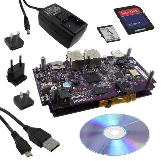
ICGOO电子元器件商城为您提供TMDSSK3358由Texas Instruments设计生产,在icgoo商城现货销售,并且可以通过原厂、代理商等渠道进行代购。 TMDSSK3358价格参考¥2264.12-¥2264.12。Texas InstrumentsTMDSSK3358封装/规格:评估板 - 嵌入式 - MCU,DSP, AM3358ZCZ Sitara™ MPU ARM® Cortex®-A8 Embedded Evaluation Board。您可以下载TMDSSK3358参考资料、Datasheet数据手册功能说明书,资料中有TMDSSK3358 详细功能的应用电路图电压和使用方法及教程。
Texas Instruments(德州仪器)的TMDSSK3358评估板是一款专为嵌入式系统设计的开发平台,主要用于评估和开发基于Sitara AM335x系列处理器的应用。AM335x是一款集成了ARM Cortex-A8内核的微处理器(MCU),适用于多种工业、消费类和通信领域的应用场景。

 主要应用场景:

1. 工业自动化与控制:
   TMDSSK3358可以用于开发工业自动化控制系统,如PLC(可编程逻辑控制器)、HMI(人机界面)和智能传感器等。其强大的处理能力和丰富的外设接口使其能够高效地处理复杂的工业协议和实时控制任务。

2. 楼宇自动化:
   该评估板可用于开发楼宇自动化系统,包括智能照明、温度控制、安防监控等。通过集成Wi-Fi、以太网等通信模块,可以实现设备之间的互联互通,支持智能家居和智能建筑的建设。

3. 智能电网与能源管理:
   TMDSSK3358适合用于开发智能电表、能源管理系统和分布式发电控制设备。它可以通过高速数据采集和处理能力,实时监测和优化电力使用,提高能源效率。

4. 医疗设备:
   在医疗领域,TMDSSK3358可以用于开发便携式医疗设备、监护仪和其他需要高性能处理和低功耗的医疗仪器。其强大的计算能力和丰富的I/O接口可以满足医疗设备对数据处理和通信的需求。

5. 物联网(IoT)应用:
   该评估板非常适合用于开发物联网节点设备,如智能网关、边缘计算设备等。通过集成各种传感器和通信模块,可以实现数据采集、处理和传输,支持大规模物联网部署。

6. 车载信息系统:
   TMDSSK3358还可以用于开发车载信息娱乐系统、远程信息处理系统等。其高可靠性和扩展性使得它能够在汽车环境中稳定运行,提供丰富的多媒体功能和导航服务。

总之,TMDSSK3358评估板凭借其强大的处理性能、丰富的外设接口和灵活的开发环境,广泛应用于多个领域,帮助开发者快速构建和测试基于AM335x处理器的各种嵌入式应用。
| 参数 | 数值 |
| 产品目录 | 编程器,开发系统嵌入式解决方案 |
| 描述 | KIT DEV STARTER FOR AM335X开发板和工具包 - ARM TMDSSK3358 Starter Kit |
| 产品分类 | 评估板 - 嵌入式 - MCU, DSP工程工具 |
| 品牌 | Texas Instruments |
| 产品手册 | http://www.ti.com/tool/tmdssk3358 |
| 产品图片 |
|
| rohs | 符合RoHS含铅 / 不受限制有害物质指令(RoHS)规范要求限制 |
| 产品系列 | 嵌入式开发工具,嵌入式处理器开发套件,开发板和工具包 - ARM,Texas Instruments TMDSSK3358Sitara™ |
| mouser_ship_limit | 此产品可能需要其他文件才能从美国出口。 |
| 数据手册 | http://www.ti.com/lit/pdf/sprabo4http://www.ti.com/lit/pdf/spruhd7点击此处下载产品Datasheet点击此处下载产品Datasheet |
| 产品型号 | TMDSSK3358 |
| 产品 | Starter Kits |
| 产品培训模块 | http://www.digikey.cn/PTM/IndividualPTM.page?site=cn&lang=zhs&ptm=26006 |
| 产品种类 | 开发板和工具包 - ARM |
| 其它名称 | 296-34889 |
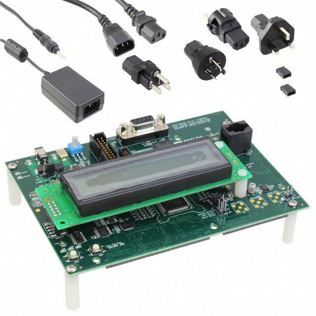
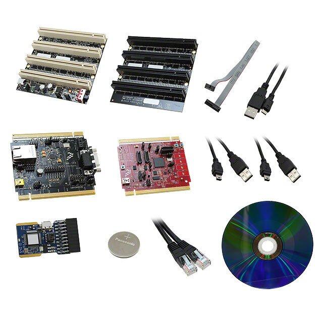
| 内容 | 板,电缆,LCD,电源 |
| 制造商产品页 | http://www.ti.com/general/docs/suppproductinfo.tsp?distId=10&orderablePartNumber=TMDSSK3358 |
| 商标 | Texas Instruments |
| 安装类型 | 固定 |
| 尺寸 | 5.257 in x 2.798 in |
| 工作电源电压 | 5 V |
| 工具用于评估 | AM3358 |
| 工厂包装数量 | 1 |
| 平台 | - |
| 接口类型 | USB |
| 操作系统 | Android,Linux |
| 板类型 | 评估平台 |
| 标准包装 | 1 |
| 核心 | ARM Cortex A8 |
| 核心处理器 | ARM® Cortex®-A8 |
| 类型 | MPU |
| 配套使用产品/相关产品 | AM3358ZCZ |


- 商务部:美国ITC正式对集成电路等产品启动337调查
- 曝三星4nm工艺存在良率问题 高通将骁龙8 Gen1或转产台积电
- 太阳诱电将投资9.5亿元在常州建新厂生产MLCC 预计2023年完工
- 英特尔发布欧洲新工厂建设计划 深化IDM 2.0 战略
- 台积电先进制程称霸业界 有大客户加持明年业绩稳了
- 达到5530亿美元!SIA预计今年全球半导体销售额将创下新高
- 英特尔拟将自动驾驶子公司Mobileye上市 估值或超500亿美元
- 三星加码芯片和SET,合并消费电子和移动部门,撤换高东真等 CEO
- 三星电子宣布重大人事变动 还合并消费电子和移动部门
- 海关总署:前11个月进口集成电路产品价值2.52万亿元 增长14.8%


PDF Datasheet 数据手册内容提取
AM335xStarterKitHardwareUsersGuide -Texas Instruments Embedded Processors Wiki Page 1of 22 AM335xStarterKitHardwareUsersGuide From Texas Instruments Embedded Processors Wiki AM335xStarterKitHardwareUsersGuide Translate this page to cs - Česky Translate AM335x Starter Kit Hardware User Guide Search Contents 1 Introduction 2 Description 3 EVM System View 3.1 Top view 3.2 Bottom view 3.3 System view 4 Functional Block Diagram 4.1 Processor 4.2 Clocks 4.3 Reset Signals 4.4 Power 4.5 Power Management IC 4.6 Configuration/Setup 4.6.1 Boot Configuration 4.6.2 I2C Port Address Assignments 4.7 Memories Supported 4.7.1 DDR3 SDRAM 4.7.2 Board Identity Memory 4.7.3 SD/MMC0 4.8 Ethernet 4.9 USB 4.9.1 USB to UART/JTAG 4.9.2 USB 1 4.10 Audio Codec 4.11 WLAN 4.12 User LEDs 4.13 User Keys 4.14 Accelerometer 5 Pin Use Description 5.1 GPIO Definitions 6 Board Expansion Connectors 7 LCD 8 EVM Important Notice 8.1 EVALUATION BOARD/KIT/MODULE (EVM) ADDITIONAL TERMS 8.2 REGULATORY COMPLIANCE INFORMATION 8.3 EVALUATION BOARD/KIT/MODULE (EVM)WARNINGS, RESTRICTIONS mhtml:file://C:\Users\peggy_kraemer\Desktop\AM335xStarterKit_Web.mht 9/4/2012
AM335xStarterKitHardwareUsersGuide -Texas Instruments Embedded Processors Wiki Page 2of 22 AND DISCLAIMERS 9 ANNEX Introduction This document provides the design information on the AM335x processor based Starter Kit (TMDSSK3358) to users. Description The AM335x Starter Kit (TMDSSK3358) can be used as an evaluation and development platform for low cost AM335x based solutions and networking platforms. The embedded emulation logic allows emulation and debug using standard development tools such as TI’s Code Composer Studio by just using the supplied USB cable. It is not intended for use in end products. All of the design information is freely available and can be used as the basis for the development of an AM335x based product. EVM System View TMDSSK3358 is partitioned into two different boards: the main board (processor, peripherals & the main power supply) and the LCD Carrier board (LCD and touch screen). The TMDSSK3358 main board and the LCD carrier board mounted are mounted together using 10mm standoffs. The TMDSSK3358 main board has dimensions of 5.257” x 2.798 “and that of the LCD Carrier board is 4.963” x 2.798 “. The Top and the Bottom side views of the TMDSSK3358 are shown in the pictures provided below. Top view mhtml:file://C:\Users\peggy_kraemer\Desktop\AM335xStarterKit_Web.mht 9/4/2012
AM335xStarterKitHardwareUsersGuide -Texas Instruments Embedded Processors Wiki Page 3of 22 Figure 1: TMDSSK3358 Top view Bottom view mhtml:file://C:\Users\peggy_kraemer\Desktop\AM335xStarterKit_Web.mht 9/4/2012
AM335xStarterKitHardwareUsersGuide -Texas Instruments Embedded Processors Wiki Page 4of 22 Figure 2: TMDSSK3358 V1.2A Bottom View System view mhtml:file://C:\Users\peggy_kraemer\Desktop\AM335xStarterKit_Web.mht 9/4/2012
AM335xStarterKitHardwareUsersGuide -Texas Instruments Embedded Processors Wiki Page 5of 22 Figure 3: TMDSSK3358 System View Functional Block Diagram This section describes about the major functional blocks of the TMDSSK3358. The Functional block diagram of the TMDSSK3358 design is shown below. mhtml:file://C:\Users\peggy_kraemer\Desktop\AM335xStarterKit_Web.mht 9/4/2012
AM335xStarterKitHardwareUsersGuide -Texas Instruments Embedded Processors Wiki Page 6of 22 Figure 4: TMDSSK3358 Block Diagram Processor The AM3358ZCZ processor is the central processor for TMDSSK3358. All the resources on the board surround the AM3358 processor to provide development capabilities for hardware and software. See the AM3358 datasheet and TRM for the details about the processor. There are system configuration signals, SYSBOOT, that can be set on the EVM to define some startup parameters on the AM335x processor. See the Configuration/Setup section later for more details. Clocks The main clock for the processor is derived from a 24MHz crystal. An on-board oscillator in the AM3358 generates the base clock and subsequent module clocks as needed within the AM3358 processor. A 32kHz clock for the RTC on the AM3358 is derived from a 32kHz crystal on board. Reset Signals Power On Reset to the AM335x is driven by the PMIC. SYS_ WARMRESETn is a signal running to mhtml:file://C:\Users\peggy_kraemer\Desktop\AM335xStarterKit_Web.mht 9/4/2012
AM335xStarterKitHardwareUsersGuide -Texas Instruments Embedded Processors Wiki Page 7of 22 several peripherals and AM335x which performs a reset on those peripherals. SYS_WARMRESETn is asserted by a pushbutton on the main board and is used to force a reset of the AM335x. AM335x can also pull down on the RESET_INOUTn signal to cause the SYS_ WARMRESETn line to go active. The RTC_PORZ reset signal for the RTC section is derived using AND Gates. Power The power input to TMDSSK3358 is from a 5V Power Supply. This 5V power is provided as power input to the Power Manager TPS65910A3. The power requirements of the processor are taken care of by the Power Manager IC TPS65910A3. The Power ON LED "D5" is ON if the PMIC output power VAUX33 is available ( to indicate the active status of the PMIC). The power sequencing requirements of the AM335X processor (see the AM335x datasheet) are handled automatically by the TPS65910A3 PMIC. Note: When powering the TMDSSK3358 EVM, always use the supplied power supply (CUI/V- Infinity Part Number EMSA050300-P6P-SZ, Model 3A-182WP05) or equivalent model having output voltage of +5VDC and output current max 3.0 Amps. Power Management IC TMDSSK3358 uses the TPS65910A3 power management IC. The I2C0 on AM335x is used to control the TPS65910A PMIC. The PWRON input of PMIC is connected to an external push-button. The built-in debouncing time defines a minimum button press duration that is required for button press detection. Any button press duration which is lower than this value is ignored, considered an accidental touch. For AM335x, the following power supplies from the TPS65910A are used. TPS65910 Power Supply/Other AM335x Power Rail Voltage sources VAUX2 (300mA) VDDSHV6 (300mA) 3.3V VDDSHV2,3,4,5 (300 mA), VDDA3P3V_USB0/1 (10 VMMC (300mA) 3.3V mA) VDD2 SMPS (1500mA) VDD_CORE (1000mA) 1.1V VDD1 SMPS (1500mA) VDD_MPU (1500mA) 1.2V No supply needed VDD_RTC 1.1V VRTC (External LDO) VDDS_RTC (10mA) 1.8V VIO_SMPS (1000mA) VDDS_DDR (200mA) 1.5V VIO_SMPS (1000mA) DDR_VREF (10mA) 0.9V VDAC (150mA) VDDS (100mA) 1.8V VDIG1 (300mA) VDDSHV1 1.8V mhtml:file://C:\Users\peggy_kraemer\Desktop\AM335xStarterKit_Web.mht 9/4/2012
AM335xStarterKitHardwareUsersGuide -Texas Instruments Embedded Processors Wiki Page 8of 22 VDDS_SRAM_CORE_BG VDIG2 (300mA) 1.8V (40mA) VDIG2 (300mA) VDDS_SRAM_MPU_BB (40mA) 1.8V VDIG2 (300mA) VDDS_PLL_DDR (25mA) 1.8V VDIG2 (300mA) VDDS_PLL_CORE_LCD (25mA) 1.8V VDIG2 (300mA) VDDS_PLL_MPU (25mA) 1.8V VDIG2 (300mA) VDDS_OSC (10mA) 1.8V VAUX1 (300mA) VDDA1P8V_USB0/1 (50mA) 1.8V VPLL (50mA) VDDA_ADC 1.8V VDD3 SMPS (100mA) Not Used - Table 1: Power supplies to AM335x from TPS65910A3 PMIC Configuration/Setup Boot Configuration Various boot configurations can be set using the pull up / down resistor combinations provided on the SYS_BOOT pins (LCD_DATA0..15).Boot configuration pins are latched upon de-assertion of PORz pin. I2C Port Address Assignments Information on I2C address assignments are provided below. AM335x STARTER KIT (TMDSSK3358) Function AM335x I2C Port Address Baseboard ID memory I2C0 0x50 AM355x PMIC Control I2C0 0x2D AM355x PMIC Smart Reflex Control I2C0 0x12 Accelerometer Control I2C0 0x18 Audio Codec I2C0 0x1B Capacitive Touch screen I2C0 0x38 Table 2:I2C Bus Addresses Memories Supported The TMDSSK3358 design supports on-board memories like DDR3 SDRAM and Board ID EEPROM. It also supports an SD card socket. DDR3 SDRAM DDR3 SDRAM memory design is provided by using a 2 Gb single chip solution (MT41J128M16JT- mhtml:file://C:\Users\peggy_kraemer\Desktop\AM335xStarterKit_Web.mht 9/4/2012
AM335xStarterKitHardwareUsersGuide -Texas Instruments Embedded Processors Wiki Page 9of 22 125) from Micron. It is internally configured as a16 Meg x 16 x 8 bank memory. A separate Regulator to supply the DDR reference power to the AM335x and the VTT termination voltage to the termination components is provided in the design. The VIO_SMPS output from the PMIC is programmed to provide the required 1.5V to the DDR3 SDRAM. Board Identity Memory The board contains a serial EEPROM with the board specific data which allows the processor to automatically detect which board is connected and the version of that board. Other hardware specific data can be stored in this memory as well. The part number of the memory device used is CAT24C256WI-GT3. See the Configuration/Setup section for details on the data in this memory. Name Size Contents Header 4 MSB 0xEE3355AA LSB Board Name 8 Name for board in ASCII “A335X_SK” = AM335x TMDSSK3358Board Version 4 Hardware version code for board in ASCII “1.2A” = rev. 01.2A Serial number of the board. This is a 12 character string which is: Serial Number 12 WWYY4P19nnnn where: WW = 2 digit week of the year of production YY = 2 digit year of production nnnn = incrementing board number Codes to show the configuration setup on this board. For the available Configuration EVM’s supported, the following codes are used: 32 Option ASCII “SKU#00” = default configuration Remaining 26 bytes are reserved Available 32720 Available space for other non-volatile codes/data Table 3:I2C Configuration SD/MMC0 The Micro SD/MMC0 port is provided with a card socket SCHA5B0200. This is a standard Micro SD/MMC Card type of connector which is of the low profile compact type. It is connected to the MMC0 port of the AM335x processor. Check the AM335x data sheet and TRM for supported card types/densities.8Gb SD cards are tested with this design. The Pin assignment is as given below. Pin No Memory Card PIN No. uSD#1 DAT2 uSD#2 CD/DAT3 uSD #3 CMD uSD #4 VCC uSD #5 CLK uSD #6 GND uSD #7 DAT0 uSD #8 DAT1 mhtml:file://C:\Users\peggy_kraemer\Desktop\AM335xStarterKit_Web.mht 9/4/2012
AM335xStarterKitHardwareUsersGuide -Texas Instruments Embedded Processors Wiki Page 10of 22 uSD #9 GND uSD #10 CD Table 4: SD/MMC0 Connector Pin Details Ethernet TMDSSK3358 has two Giga bit Ethernet transceivers. AR8031-AL1A from Atheros is used as a single port, tri speed PHY. A single 3.3V is enough to power this PHY and the other voltages required were generated internally. Reset for both the chips are driven by the SYS_WARMRESETn signal through a SN74LVC1G07 buffer.Both the PHYs have individual 25MHz, 50ppm crystal as their clock source. The 25MHz Clock out of the EMAC1-PHY port has been connected to the XTLI of the EMAC2-PHY as an optional clock input. For both the PHYs, mode selection pins MODE [3:0] are set as “0000” to operate it in 1000 BASE-T, RGMII mode. The PHY address for the EMAC1-PHY and EMAC2-PHY are 00100 and 00101 respectively.The interrupts from the both PHYs are connected to both the Non Maskable Interrupt pin and to the processor GPIO pins. The Wake On LAN interrupts from the both PHYs are connected to the EXT_WAKEUP signal of the processor as an option. Pin No Signal Name Description 1 DGND Ground 2 NC No connect 3 ETHER_D3P MDI 3 POSITIVE 4 ETHER_D3N MDI 3 NEGATIVE 5 ETHER_D2P MDI 2 POSITIVE 6 ETHER_D2N MDI 2 NEGATIVE 7 ETHER_D1P MDI 1 POSITIVE 8 ETHER_D1N MDI 1 NEGATIVE 9 ETHER_D0P MDI 0 POSITIVE 10 ETHER_D0N MDI 0 NEGATIVE D1 PHY_ LED_ACTn PHY ACTIVITY LED signal D2 GND Ground D3 GND Ground D4 PHY_ LED_1000n 1000 Base-T LINK LED signal Table 5: 10/100 PRU Ethernet1 Pin Details USB USB to UART/JTAG mhtml:file://C:\Users\peggy_kraemer\Desktop\AM335xStarterKit_Web.mht 9/4/2012
AM335xStarterKitHardwareUsersGuide -Texas Instruments Embedded Processors Wiki Page 11of 22 Micro AB USB port is provided as an upstream port of the USB HUB USB2412. This is used for USB to JTAG and USB to UART conversion applications through the downstream port 1 of the HUB. FT2232L is used for the USB to UART and JTAG conversion applications. The Downstream port 2 of the Hub is connected to USB port 0 of the AM335x. The USB to UART/JTAG converter (FT2232L) has 32 configurable multifunction pins. A 16 bit, serial EEPROM 93LC56B from MicroChip is used to store the configuration data. Some of the pins from ADBUS [7:0] and ACBUS [7:0] are configured as JTAG and Reset signals. These JTAG pins from the FT2232 IC are connected to the dedicated processor JTAG pins and as well to the optional JTAG connector. The Micro AB USB pin out details are provided below. Pin No Signal Name Description 1 USB_DC USB BUS VOLTAGE 2 USBDM_UP USB DATA MINUS 3 USBDP_UP USB DATA PLUS 4 NC (USB_ID) No connect 5 DGND Ground Table 6: Micro AB – USB0 USB 1 The USB port1 of the AM335x is connected to the USB type A connector. USB power (5V )is provided to this connector through a buck-boost converter circuit. Pin No Signal Name Description 1 VUSB_VBUS1 USB BUS VOLTAGE 2 USB1_CONN_DM USB1 DATA MINUS 3 USB1_CONN_DP USB1 DATA PLUS 4 DGND Ground Table 7: USB A Type – USB1 Audio Codec The TLV320AIC3106 is a low-power stereo audio codec with stereo headphone amplifier from TI. CLKOUT1 of the processor is sourcing the master clock of the codec (24Mhz). The CODEC I2C is capable of supporting both the standard and fast modes. I2C address of the codec is configured as 0011011. MCASP1 interface of the processor is connected to the audio interface of the codec. The stereo audio output is terminated in a stereo headphone Jack. The Pinout assignments for the headset jack are provided below. mhtml:file://C:\Users\peggy_kraemer\Desktop\AM335xStarterKit_Web.mht 9/4/2012
AM335xStarterKitHardwareUsersGuide -Texas Instruments Embedded Processors Wiki Page 12of 22 Pin No Signal Description 1 AGND_AUD Analog Ground 3 HS_SPKRP Headset stereo LOUT 10 NC No Connect 2 HD_SPKRP Headset stereo ROUT Table 8: Headset Jack WLAN LBEE5ZSTNC-523 Type TN WiFi / BT Module from Murata is used to provide the WLAN and the Bluetooth connectivity for the TMDSSK3358 design. The WLAN design has IEEE802.11 b, g, n compliance for WLAN and Version4.0 with Blue tooth Low Energy (BLE) for BT. This module requires an external 32.768 KHz, +/-150ppm clock. This is sourced by the CLKOUT2 clock out pin of the processor. The required digital interfaces for the module are connected to the UART1 and McASP0 ports of the processor through voltage level converters. Note that due to a HW bug in the WiFi Antenna matching network design, customers may observe significant degradation in throughput (15-20 Mbps - Typical) as well as reduced WiFi Range when using the AM335x Starter Kit and COM6M module with AM335-EVM, with the onboard WiFi Antenna. For optimal throughput we recomend using an external Antenna as describe in the link:<ECO for using external antenna> Warning: To minimize risks of potential radiation hazards associated with handling and/or moving the energized EVM including compliance with the wireless radio grant licensing provisions, always maintain a minimum distance of 20cm measured between EVM user(s) and the EVM antenna. User LEDs The Four User LEDs implemented are D1-D4 in the user panel area. These are driven by the GPIOs from the AM335x. All the user LEDs are green in color. User Keys This design has 4 user keys SW1,SW2,SW3 & SW4, three of them connected directly to the GPIO bank2 of the processor (Keys 2,3 & 4) and one of them (Key 1) connected to the GPIO bank0 of the processor. Apart from the above four user keys, the design also has a button to interrupt the processor via the non maskable interrupt pin. mhtml:file://C:\Users\peggy_kraemer\Desktop\AM335xStarterKit_Web.mht 9/4/2012
AM335xStarterKitHardwareUsersGuide -Texas Instruments Embedded Processors Wiki Page 13of 22 Accelerometer The LIS331DLH is an ultra low-power high performance three axes linear accelerometer used in TMDSSK3358 board. The accelerometer is mounted closer to the center of the board as to allow the most useful/dynamic data. The accelerometer is connected via I2C0 of the processor. The I2C(0) address is 0011000b. Pin Use Description The Pin use description file provides us the information on the pin functionality mode selected. The pin mux utility file is found here File:TMDSSK3358 V1 2 Pin Mux.dat GPIO Definitions See the updated pinmux document File:TMDSSK3358 V1 2 Pin Mux.xlsx which shows the use case columns for GPIOs. Board Expansion Connectors The SPI0 and the I2C0 ports are extended through the connectors J11 and J8 respectively. SPI0 Expansion header pinout is provided below. Pin No Signal Description 1 V3_3D Power 3.3V supply 2 AM335X_SPI0_CS0 SPI0 Chip Select 0 3 AM335X_SPI0_D1 SPI0 Data 1 4 DGND Ground 5 AM335X_SPI0_SCLK SPI0 Clock 6 AM335X_SPI0_D0 SPI0 Data 0 Table 9: SPI0 Expansion Header I2C0 Expansion header is provided below. Pin No Signal Description 1 DGND Ground 2 AM335X_I2C0_SDA I2C0 DATA 3 AM335X_I2C0_SCL I2C0 Clock 4 V3_3D Power 3.3V supply mhtml:file://C:\Users\peggy_kraemer\Desktop\AM335xStarterKit_Web.mht 9/4/2012
AM335xStarterKitHardwareUsersGuide -Texas Instruments Embedded Processors Wiki Page 14of 22 Table 10: I2C0 Expansion Header LCD TFT color LCD module from Newhaven Display NHD-4.3-480272MF-ATXI#-T-1 with resistive touch screen shall be used as the LCD display for the TMDSSK3358 design. It is 4.3 inches wide and it has a built in driver and no controller is required. It has 480 X 272 pixels and supports up to 16.7M colors. This LCD supports white LED backlight. 24bit RGB signals, control signals and Resistive touch screen signals are terminated in a flex PCB with a 40 pin connector that fits into the TMDSSK3358 main board using a mating connector. 40 pin LCD connector pinout is provided here. Pin No Signal Description 1 LED- Backlight LED power supply GND 2 LED+ Backlight LED power supply voltage 3 DGND Ground 4 VCC 3.3V LCD Power Supply 5 R0 Red Data0 6 R1 Red Data1 7 R2 Red Data2 8 R3 Red Data3 9 R4 Red Data4 10 R5 Red Data5 11 R6 Red Data6 12 R7 Red Data7 13 G0 Green Data0 14 G1 Green Data1 15 G2 Green Data2 16 G3 Green Data3 17 G4 Green Data4 18 G5 Green Data5 19 G6 Green Data6 20 G7 Green Data7 21 B0 Blue Data0 22 B1 Blue Data1 23 B2 Blue Data2 24 B3 Blue Data3 25 B4 Blue Data4 26 B5 Blue Data5 mhtml:file://C:\Users\peggy_kraemer\Desktop\AM335xStarterKit_Web.mht 9/4/2012
AM335xStarterKitHardwareUsersGuide -Texas Instruments Embedded Processors Wiki Page 15of 22 27 B6 Blue Data6 28 B7 Blue Data7 29 GND Ground 30 PCLK Data Sample clock signal 31 DISP Display ON/OFF signal 32 HSYNC Line Sync signal 33 VSYNC Frame Sync signal 34 DE Data enable 35 AVDD No connect 36 GND Ground 37 XR Touch Panel Right 38 YD Touch Panel Down 39 XL Touch Panel Left 40 YU Touch Panel Up Table 11 :LCD Connector EVM Important Notice EVALUATION BOARD/KIT/MODULE (EVM) ADDITIONAL TERMS Texas Instruments (TI) provides the enclosed Evaluation Board/Kit/Module (EVM) under the following conditions: The user assumes all responsibility and liability for proper and safe handling of the goods. Further, the user indemnifies TI from all claims arising from the handling or use of the goods. Should this evaluation board/kit not meet the specifications indicated in the User's Guide, the board/ kit may be returned within 30 days from the date of delivery for a full refund. THE FOREGOING LIMITED WARRANTY IS THE EXCLUSIVE WARRANTY MADE BY SELLER TO BUYER AND IS IN LIEU OF ALL OTHER WARRANTIES, EXPRESSED, IMPLIED, OR STATUTORY, INCLUDING ANY WARRANTY OF MERCHANTABILITY OR FITNESS FOR ANY PARTICULAR PURPOSE. EXCEPT TO THE EXTENT OF THE INDEMNITY SET FORTH ABOVE, NEITHER PARTY SHALL BE LIABLE TO THE OTHER FOR ANY INDIRECT, SPECIAL, INCIDENTAL, OR CONSEQUENTIAL DAMAGES. Please read the User's Guide and, specifically, the Warnings and Restrictions notice in the User's Guide prior to handling the product. This notice contains important safety information about temperatures and voltages. For additional information on TI's environmental and/or safety programs, please visit [- http://www.ti.com/esh]www.ti.com/esh or contact TI. mhtml:file://C:\Users\peggy_kraemer\Desktop\AM335xStarterKit_Web.mht 9/4/2012
AM335xStarterKitHardwareUsersGuide -Texas Instruments Embedded Processors Wiki Page 16of 22 No license is granted under any patent right or other intellectual property right of TI covering or relating to any machine, process, or combination in which such TI products or services might be or are used. TI currently deals with a variety of customers for products, and therefore our arrangement with the user is not exclusive. TI assumes no liability for applications assistance, customer product design, software performance, or infringement of patents or services described herein. Mailing Address: Texas Instruments Post Office Box 655303 Dallas, Texas 75265 Copyright 2011, Texas Instruments Incorporated REGULATORY COMPLIANCE INFORMATION As noted in the EVM User’s Guide and/or EVM itself, this EVM and/or accompanying hardware may or may not be subject to the Federal Communications Commission (FCC) and Industry Canada (IC) rules For EVMs not subject to the above rules, this evaluation board/kit/module is intended for use for ENGINEERING DEVELOPMENT, DEMONSTRATION OR EVALUATION PURPOSES ONLY and is not considered by TI to be a finished end product fit for general consumer use. It generates, uses, and can radiate radio frequency energy and has not been tested for compliance with the limits of computing devices pursuant to part 15 of FCC or ICES-003 rules, which are designed to provide reasonable protection against radio frequency interference. Operation of the equipment may cause interference with radio communications, in which case the user at his own expense will be required to take whatever measures may be required to correct this interference. General Statement for EVMs including a radio User Power/Frequency Use Obligations: This radio is intended for development/professional use only in legally allocated frequency and power limits. Any use of radio frequencies and/or power availability of this EVM and its development application(s) must comply with local laws governing radio spectrum allocation and power limits for this evaluation module. It is the user's sole responsibility to only operate this radio in legally acceptable frequency space and within legally mandated power limitations. Any exceptions to this is strictly prohibited and unauthorized by Texas Instruments unless user has obtained appropriate experimental/development licenses from local regulatory authorities, which is responsibility of user including its acceptable authorization. For EVMs annotated as FCC – FEDERAL COMMUNICATIONS COMMISSION Part 15 Compliant Caution This device complies with part 15 of the FCC Rules. Operation is subject to the following two conditions: (1) This device may not cause harmful interference, and (2) this deice must accept any interference received, including interference that may cause undesired operation. mhtml:file://C:\Users\peggy_kraemer\Desktop\AM335xStarterKit_Web.mht 9/4/2012
AM335xStarterKitHardwareUsersGuide -Texas Instruments Embedded Processors Wiki Page 17of 22 Changes or modifications not expressly approved by the party responsible for compliance could void the user's authority to operate the equipment. FCC Interference Statement for Class A EVM devices This equipment has been tested and found to comply with the limits for a Class A digital device, pursuant to part 15 of the FCC Rules. These limits are designed to provide reasonable protection against harmful interference when the equipment is operated in a commercial environment. This equipment generates, uses, and can radiate radio frequency energy and, if not installed and used in accordance with the instruction manual, may cause harmful interference to radio communications. Operation of this equipment in a residential area is likely to cause harmful interference in which case the user will be required to correct the interference at his own expense. FCC Interference Statement for Class B EVM devices This equipment has been tested and found to comply with the limits for a Class B digital device, pursuant to part 15 of the FCC Rules. These limits are designed to provide reasonable protection against harmful interference in a residential installation. This equipment generates, uses and can radiate radio frequency energy and, if not installed and used in accordance with the instructions, may cause harmful interference to radio communications. However, there is no guarantee that interference will not occur in a particular installation. If this equipment does cause harmful interference to radio or television reception, which can be determined by turning the equipment off and on, the user is encouraged to try to correct the interference by one or more of the following measures: Reorient or relocate the receiving antenna. Increase the separation between the equipment and receiver. Connect the equipment into an outlet on a circuit different from that to which the receiver is connected. Consult the dealer or an experienced radio/TV technician for help. For EVMs annotated as IC – INDUSTRY CANADA Compliant This Class A or B digital apparatus complies with Canadian ICES-003. Changes or modifications not expressly approved by the party responsible for compliance could void the user's authority to operate the equipment. Concerning EVMs including radio transmitters This device complies with Industry Canada licence-exempt RSS standard(s). Operation is subject to the following two conditions: (1) this device may not cause interference, and (2) this device must accept any mhtml:file://C:\Users\peggy_kraemer\Desktop\AM335xStarterKit_Web.mht 9/4/2012
AM335xStarterKitHardwareUsersGuide -Texas Instruments Embedded Processors Wiki Page 18of 22 interference, including interference that may cause undesired operation of the device. Concerning EVMs including detachable antennas Under Industry Canada regulations, this radio transmitter may only operate using an antenna of a type and maximum (or lesser) gain approved for the transmitter by Industry Canada. To reduce potential radio interference to other users, the antenna type and its gain should be so chosen that the equivalent isotropically radiated power (e.i.r.p.) is not more than that necessary for successful communication. This radio transmitter has been approved by Industry Canada to operate with the antenna types listed in the user guide with the maximum permissible gain and required antenna impedance for each antenna type indicated. Antenna types not included in this list, having a gain greater than the maximum gain indicated for that type, are strictly prohibited for use with this device. \~ Cet appareil numérique de la classe A ou B est conforme à la norme NMB-003 du Canada. Les changements ou les modifications pas expressément approuvés par la partie responsable de la conformité ont pu vider l'autorité de l'utilisateur pour actionner l'équipement. Concernant les EVMs avec appareils radio Le présent appareil est conforme aux CNR d'Industrie Canada applicables aux appareils radio exempts de licence. L'exploitation est autorisée aux deux conditions suivantes : (1) l'appareil ne doit pas produire de brouillage, et (2) l'utilisateur de l'appareil doit accepter tout brouillage radioélectrique subi, même si le brouillage est susceptible d'en compromettre le fonctionnement. Concernant les EVMs avec antennes détachables Conformément à la réglementation d'Industrie Canada, le présent émetteur radio peut fonctionner avec une antenne d'un type et d'un gain maximal (ou inférieur) approuvé pour l'émetteur par Industrie Canada. Dans le but de réduire les risques de brouillage radioélectrique à l'intention des autres utilisateurs, il faut choisir le type d'antenne et son gain de sorte que la puissance isotrope rayonnée équivalente (p.i.r.e.) ne dépasse pas l'intensité nécessaire à l'établissement d'une communication satisfaisante. Le présent émetteur radio a été approuvé par Industrie Canada pour fonctionner avec les types d'antenne énumérés dans le manuel d'usage et ayant un gain admissible maximal et l'impédance requise pour chaque type d'antenne. Les types d'antenne non inclus dans cette liste, ou dont le gain est supérieur au gain maximal indiqué, sont strictement interdits pour l'exploitation de l'émetteur. mhtml:file://C:\Users\peggy_kraemer\Desktop\AM335xStarterKit_Web.mht 9/4/2012
AM335xStarterKitHardwareUsersGuide -Texas Instruments Embedded Processors Wiki Page 19of 22 【Important Notice for Users of this Product in Japan】 This development kit is NOT certified as Confirming to Technical Regulations of Radio Law of Japan! If you use this product in Japan, you are required by Radio Law of Japan to follow the instructions below with respect to this product: (1) Use this product in a shielded room or any other test facility as defined in the notification \#173 issued by Ministry of Internal Affairs and Communications on March 28, 2006, based on Sub-section 1.1 of Article 6 of the Ministry's Rule for Enforcement of Radio Law of Japan, (2) Use this product only after you obtained the license of Test Radio Station as provided in Radio Law of Japan with respect to this product, or (3) Use of this product only after you obtained the Technical Regulations Conformity Certification as provided in Radio Law of Japan with respect to this product. Also, please do not transfer this product, unless you give the same notice above to the transferee. Please note that if you could not follow the instructions above, you will be subject to penalties of Radio Law of Japan. Texas Instruments Japan Limited (address) 24-1, Nishi-Shinjuku 6 chome, Shinjukku-ku, Tokyo, Japan http://www.tij.co.jp/ 【ご使用にあたっての注意】 本開発キットは技術基準適合証明を受けておりません。 本製品のご使用に際しては、電波法遵守のため、以下のいずれかの措置を取っていただく必要が ありますのでご注意ください。 (1)電波法施行規則第6条第1項第1号に基づく平成18年3月28日総務省告示第173号で定められ た電波暗室等の試験設備でご使用いただく。 (2)実験局の免許を取得後ご使用いただく。 (3)技術基準適合証明を取得後ご使用いただく。 なお、本製品は、上記の「ご使用にあたっての注意」を譲渡先、移転先に通知しない限り、譲渡、移転できないものとします。 上記を遵守頂けない場合は、電波法の罰則が適用される可能性があることをご留意くださ い。 日本テキサス・インスツルメンツ株式会社 mhtml:file://C:\Users\peggy_kraemer\Desktop\AM335xStarterKit_Web.mht 9/4/2012
AM335xStarterKitHardwareUsersGuide -Texas Instruments Embedded Processors Wiki Page 20of 22 東京都新宿区西新宿6丁目24番1号 西新宿三井ビル http://www.tij.co.jp/ EVALUATION BOARD/KIT/MODULE (EVM)WARNINGS, RESTRICTIONS AND DISCLAIMERS For Feasibility Evaluation Only, in Laboratory/Development Environments. Unless otherwise indicated, this EVM is not a finished electrical equipment and not intended for consumer use. It is intended solely for use for preliminary feasibility evaluation in laboratory/development environments by technically qualified electronics experts who are familiar with the dangers and application risks associated with handling electrical mechanical components, systems and subsystems. It should not be used as all or part of a finished end product. Your Sole Responsibility and Risk. You acknowledge, represent and agree that: 1. You have unique knowledge concerning Federal, State and local regulatory requirements (including but not limited to Food and Drug Administration regulations, if applicable) which relate to your products and which relate to your use (and/or that of your employees, affiliates, contractors or designees) of the EVM for evaluation, testing and other purposes. 2. You have full and exclusive responsibility to assure the safety and compliance of your products with all such laws and other applicable regulatory requirements, and also to assure the safety of any activities to be conducted by you and/or your employees, affiliates, contractors or designees, using the EVM. Further, you are responsible to assure that any interfaces (electronic and/or mechanical) between the EVM and any human body are designed with suitable isolation and means to safely limit accessible leakage currents to minimize the risk of electrical shock hazard. 3. You will employ reasonable safeguards to ensure that your use of the EVM will not result in any property damage, injury or death, even if the EVM should fail to perform as described or expected. 4. You will take care of proper disposal and recycling of the EVM's electronic components and packing materials Certain Instructions. It is important to operate this EVM within the input voltage range of 2.7 V to 5.5 V and the output voltage range of -10 V to 15 V. Exceeding these EVM ratings may cause property damage, personal injury or death. If there are questions concerning these ratings please contact a TI field representative prior to connecting interface electronics including input power and intended loads. Any loads applied outside of the specified output range may result in unintended and/or inaccurate operation and/or possible permanent damage to the EVM and/or interface electronics. Please consult the EVM User's Guide prior to connecting any load to the EVM output. If there is uncertainty as to the load specification, please contact a TI field representative. During normal operation, some circuit components may have case temperatures greater than 60°C as long as the input and output are maintained at a normal ambient operating temperature. These components include but are not limited to linear regulators, switching transistors, pass transistors, and current sense resistors which can be identified using the EVM schematic located in the EVM User's Guide. When placing measurement mhtml:file://C:\Users\peggy_kraemer\Desktop\AM335xStarterKit_Web.mht 9/4/2012
AM335xStarterKitHardwareUsersGuide -Texas Instruments Embedded Processors Wiki Page 21of 22 probes near these devices during normal operation, please be aware that these devices may be very warm to the touch. As with all electronic evaluation tools, only qualified personnel knowledgeable in electronic measurement and diagnostics normally found in development environments should use these EVMs. Agreement to Defend, Indemnify and Hold Harmless. You agree to defend, indemnify and hold TI, its licensors and their representatives harmless from and against any and all claims, damages, losses, expenses, costs and liabilities (collectively, "Claims") arising out of or in connection with any use of the EVM that is not in accordance with the terms of the agreement. This obligation shall apply whether Claims arise under law of tort or contract or any other legal theory, and even if the EVM fails to perform as described or expected. Safety-Critical or Life-Critical Applications. If you intend to evaluate the components for possible use in safety critical applications (such as life support) where a failure of the TI product would reasonably be expected to cause severe personal injury or death, such as devices which are classified as FDA Class III or similar classification, then you must specifically notify TI of such intent and enter into a separate Assurance and Indemnity Agreement. ANNEX This Hardware User's Guide is prepared by using the following documents as references. 1. AM335x Sitara ARM Microprocessors TRM (SPRUH73) For technical support please post your questions at http://e2e.ti.com/. Please post only comments about the article AM335xStarterKitHardwareUsersGuide here. Links ARM Digital Digital ARM Microcontroller Multi Core Microcontroller Media Signal Processor MCU Processor MCU Processor Processing Ultra Low 8 bit Microcontroller 16 bit Microcontroller 32 bit Microcontroller Power DSP MCU MCU MCU Retrieved from "http://processors.wiki.ti.com/index.php/AM335xStarterKitHardwareUsersGuide" Categories: AM335x | AM335xHW Leave a Comment Comments Comments on AM335xStarterKitHardwareUsersGuide mhtml:file://C:\Users\peggy_kraemer\Desktop\AM335xStarterKit_Web.mht 9/4/2012
AM335xStarterKitHardwareUsersGuide -Texas Instruments Embedded Processors Wiki Page 22of 22 Anunakin said ... I see 2GB as RAM size, its OK? because estore.ti.com show me 256MB, I think 256MB is correct. --Anunakin 18:10, 31 August 2012 (CDT) This page was last modified on 4 September 2012, at 03:11. This page has been accessed 1,439 times. Content is available under Creative Commons Attribution-Share Alike 3.0 license. Privacy policy About Texas Instruments Embedded Processors Wiki Disclaimers mhtml:file://C:\Users\peggy_kraemer\Desktop\AM335xStarterKit_Web.mht 9/4/2012