ICGOO在线商城 > MS3102A36-5P
 Datasheet下载
- 型号: MS3102A36-5P
- 制造商: Amphenol
- 库位|库存: xxxx|xxxx
- 要求:
| 数量阶梯 | 香港交货 | 国内含税 |
| +xxxx | $xxxx | ¥xxxx |
查看当月历史价格
查看今年历史价格
MS3102A36-5P产品简介:
ICGOO电子元器件商城为您提供MS3102A36-5P由Amphenol设计生产,在icgoo商城现货销售,并且可以通过原厂、代理商等渠道进行代购。 提供MS3102A36-5P价格参考¥340.92-¥481.80以及AmphenolMS3102A36-5P封装/规格参数等产品信息。 你可以下载MS3102A36-5P参考资料、Datasheet数据手册功能说明书, 资料中有MS3102A36-5P详细功能的应用电路图电压和使用方法及教程。
| 参数 | 数值 |
| 产品目录 | |
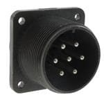
| 描述 | CONN RCPT 4POS BOX MNT W/PINS环形MIL规格连接器 4P SIZE 36 BOX MOUNT RECEPTACLE PIN 5015 |
| 产品分类 | |
| 品牌 | Amphenol Industrial |
| MIL类型 | MIL-DTL-5015 |
| 产品手册 | |
| 产品图片 | |
| rohs | 否含铅 / 不符合限制有害物质指令(RoHS)规范要求 |
| 产品系列 | 环形MIL规格连接器,环形MIL规格连接器,Amphenol Industrial MS3102A36-5PMIL-5015 衍生 |
| 数据手册 | |
| 产品型号 | MS3102A36-5P |
| 产品培训模块 | http://www.digikey.cn/PTM/IndividualPTM.page?site=cn&lang=zhs&ptm=25050http://www.digikey.cn/PTM/IndividualPTM.page?site=cn&lang=zhs&ptm=25182 |
| 产品种类 | 环形MIL规格连接器 |
| 产品类型 | Receptacles |
| 位置数量 | 4 |
| 侵入防护 | - |
| 其它名称 | MS3102A36-5P-ND |
| 包装 | 散装 |
| 商标 | Amphenol Industrial |
| 商标名 | 5015 |
| 外壳大小 | 36 |
| 外壳尺寸-插件 | 36-5 |
| 外壳尺寸,MIL | - |
| 外壳材料,镀层 | 铝合金, 草绿色,镀镉 |
| 外壳电镀 | Olive Drab Chromate over Cadmium |
| 外壳类型 | Box Mount |
| 安装类型 | 面板安装,法兰 |
| 工作温度 | -55°C ~ 125°C |
| 插入安排 | 36-5 |
| 朝向 | N(正常型) |
| 标准包装 | 1 |
| 特性 | - |
| 电压-额定 | 500VAC,700VDC |
| 端接 | 焊杯 |
| 系列 | MS 5015 |
| 紧固类型 | 有螺纹 |
| 触头镀层 | 银 |
| 触头镀层厚度 | - |
| 触点类型 | Pin (Male) |
| 连接器类型 | 插座,公形引脚 |
| 配套产品 | /product-detail/zh/MS3108A36-5S/AMS3108A36-5S-ND/2129705/product-detail/zh/MS3106A36-5S/AMS3106A36-5S-ND/2128746 |
| 针脚数 | 4 |
| 零件号别名 | MS31O2A36-5P |
| 额定电流 | - |


- 商务部:美国ITC正式对集成电路等产品启动337调查
- 曝三星4nm工艺存在良率问题 高通将骁龙8 Gen1或转产台积电
- 太阳诱电将投资9.5亿元在常州建新厂生产MLCC 预计2023年完工
- 英特尔发布欧洲新工厂建设计划 深化IDM 2.0 战略
- 台积电先进制程称霸业界 有大客户加持明年业绩稳了
- 达到5530亿美元!SIA预计今年全球半导体销售额将创下新高
- 英特尔拟将自动驾驶子公司Mobileye上市 估值或超500亿美元
- 三星加码芯片和SET,合并消费电子和移动部门,撤换高东真等 CEO
- 三星电子宣布重大人事变动 还合并消费电子和移动部门
- 海关总署:前11个月进口集成电路产品价值2.52万亿元 增长14.8%


PDF Datasheet 数据手册内容提取
None
Table of Contents Page Introduction . . . . . . . . . . . . . . . . . . . . . . . . . . . . . . . . . . . . . . 2 Amphenol® MIL-DTL-5015 and MIL-5015 Type Standard Cylindrical Connectors General Information, Class Designations . . . . . . . . . . . . . . . . . . . . . . . . . . . . . 3 MS-A, MS-C General Information . . . . . . . . . . . . . . . . . . . . . . . . . . . . . 4 MS3100A or C wall mounting receptacle . . . . . . . . . . . . . . . . . . . . . . . . . 5 MS3101A cable connecting plug . . . . . . . . . . . . . . . . . . . . . . . . . . . . 6 MS3102A or C box mounting receptacle . . . . . . . . . . . . . . . . . . . . . . . . . 7 MS3106A straight plug . . . . . . . . . . . . . . . . . . . . . . . . . . . . . . . 8 MS3108A 90 degree plug . . . . . . . . . . . . . . . . . . . . . . . . . . . . . . 9 MS-E/F General Information . . . . . . . . . . . . . . . . . . . . . . . . . . . . . . 10 MS3100E/F wall mounting receptacle . . . . . . . . . . . . . . . . . . . . . . . . . 11 MS3101E/F cable connecting plug . . . . . . . . . . . . . . . . . . . . . . . . . . 12 MS3102E box mounting receptacle . . . . . . . . . . . . . . . . . . . . . . . . . . 13 MS3106E/F straight plug . . . . . . . . . . . . . . . . . . . . . . . . . . . . . 14 MS3108E 90 degree plug . . . . . . . . . . . . . . . . . . . . . . . . . . . . . 15 MS-R General Information. . . . . . . . . . . . . . . . . . . . . . . . . . . . . . . 16 MS3100R wall mounting receptacle . . . . . . . . . . . . . . . . . . . . . . . . . . 17 MS3101R cable connecting plug. . . . . . . . . . . . . . . . . . . . . . . . . . . 18 MS3102R box mounting receptacle . . . . . . . . . . . . . . . . . . . . . . . . . . 19 MS3106R straight plug . . . . . . . . . . . . . . . . . . . . . . . . . . . . . . 20 Contact and Insert Arrangements . . . . . . . . . . . . . . . . . . . . . . . . . . . . 21 MS/Standard insert arrangement charts . . . . . . . . . . . . . . . . . . . . . . . 22, 23 MS/Standard special insert arrangement chart . . . . . . . . . . . . . . . . . . . . . . 24 MS/Standard alternate positioning . . . . . . . . . . . . . . . . . . . . . . . . . . 25 MS/Standard contact arrangements. . . . . . . . . . . . . . . . . . . . . . . . . 26 – 37 MS/Standard special contact arrangements . . . . . . . . . . . . . . . . . . . . . . 38 – 48 MS/Standard thermocouple contact arrangements . . . . . . . . . . . . . . . . . . . . 49 – 53 MS/Standard Accessories. . . . . . . . . . . . . . . . . . . . . . . . . . . . . . . 54 MS3057A cable clamp, MS3420 sleeve. . . . . . . . . . . . . . . . . . . . . . . . . 55 10-305200 cable clamp, MS3420( )A sleeve. . . . . . . . . . . . . . . . . . . . . . . 56 10-350349 cable clamp, MS3420( )A sleeve. . . . . . . . . . . . . . . . . . . . . . . 57 10-74900 cable clamp . . . . . . . . . . . . . . . . . . . . . . . . . . . . . . 58 Thru-bulkhead shells . . . . . . . . . . . . . . . . . . . . . . . . . . . . . 59, 60 Assembly instructions for 10-305200 and 10-74900 cable clamps . . . . . . . . . . . . . . . . 61 Grommet/sealing plugs. . . . . . . . . . . . . . . . . . . . . . . . . . . . . . 62 Plug protection caps . . . . . . . . . . . . . . . . . . . . . . . . . . . . . . 63 Receptacle protection caps . . . . . . . . . . . . . . . . . . . . . . . . . . . . 64 Dust caps . . . . . . . . . . . . . . . . . . . . . . . . . . . . . . . . . . 65 Sealing gaskets . . . . . . . . . . . . . . . . . . . . . . . . . . . . . . . . 66 Solder contacts . . . . . . . . . . . . . . . . . . . . . . . . . . . . . . . . 67 Crimp contacts . . . . . . . . . . . . . . . . . . . . . . . . . . . . . . . . 68 MS/Standard Application Tools . . . . . . . . . . . . . . . . . . . . . . . . . . . . . 69 MS/Standard How to Order . . . . . . . . . . . . . . . . . . . . . . . . . . . . . . 70 Additional MS/Standard Connectors offered by Amphenol Matrix® MIL-DTL-5015 with crimp rear release contacts, MIL-5015 Type Modification Connectors, 97 Series (5015 type) Connectors, Pre-Earth FMLB Connectors . . . . . . . . . . . . . . . . . 71 Amphe-Power® 5015 Connectors (AC threaded series with high amperage RADSOK® contacts), MIL-5015 Connectors with PCB contacts . . . . . . . . . . . . . . . . . . . . . . . . 72 Sales Office Listing 1
This catalog covers Amphenol® MIL-DTL-5015 connectors and MIL-5015 type connectors. MIL-C-5015 has been replaced as follows: Environmental Classes F and R are updated to and produced in strict accordance to MIL-DTL-5015. Classes A, C and E are still produced, but are no longer listed on the qualified products listing (QPL). Amphenol gives the user the largest selection of MS/Standard cylindrical connectors available in the market place. This catalog is divided into three sections; the first section by service class, a second section by contacts and insert arrangements, and a third section for accessories. Each section is prefixed with an overview to assist the user in determining selections. Should more information be required concerning the connectors covered in this publication, or if special application needs arise, please contact: Amphenol Corporation Amphenol Industrial Operations 40-60 Delaware Avenue Sidney, New York 13838-1395 Telephone 607-563-5011 Fax: 607-563-5157 www.amphenol-industrial.com Now, also offered within the broad family of Amphenol interconnection products is the Amphenol®/Matrix® MIL-DTL-5015* connector series which incorporates rear release crimp contacts. See page 71 for further description and for complete details ask for catalog 12-026. Also ask for these additional product catalogs: (cid:127) Amphenol Industrial Connector Brochure, SL-381, for an overview of the industrial family of connectors. (cid:127) Amphenol Catalog SL-100, which provides an overview of all prod- ucts, military and industrial, offered through Amphenol Aerospace. (cid:127) Amphenol Amphe-Power ® Brochure SL-391, for AC 5015 type con- nectors with RADSOK® high amperage contacts. See reference on page 72. * Note: MIL-C-5015 is superceded to MIL-DTL-5015 for all Amphenol/Matrix rear release crimp type connectors. Amphenol Aerospace operates Quality Systems that are Certified to ISO-9001 and AS-9100 by third party Registrars. 2
Amphenol® MIL-DTL-5015 and MIL-5015 Type Standard Cylindrical Connectors DESIGN CHARACTERISTICS • Medium to heavy weight cylindrical (cid:127) Durable, field-proven design (cid:127) Environmental resistant (cid:127) Resilient inserts (cid:127) Operating voltage to 3000 VAC (RMS) at sea level (cid:127) Threaded couplings (cid:127) Single key/keyway shell polarization (cid:127) Cost effective CUSTOMER OPTIONS (cid:127) Five shell styles (cid:127) Nineteen shell sizes (cid:127) 305 contact arrangements from 1 to 104 circuits (cid:127) Solder or crimp contacts, sizes 16-0 accepting MS-A, MS-C 22-0 AWG. (cid:127) Coaxial and thermocouple contact options (cid:127) Five class designations (cid:127) Alternate insert positioning (cid:127) Hermetic configurations available (cid:127) Zinc alloy plating (cadmium-free) available MS connectors meet the latest performance require- ments of MIL-DTL-5015. These connectors represent well-proven electrical capability at an acceptable cost for most equipment where durability is important. MIL-DTL-5015 features threaded couplings and single key/keyway polarization, representing maximum simplic- ity in design. Applications include military ground support MS-E/F equipment, ordnance and shipboard installations. Amphenol Industrial Operations manufactures five classes of connectors to meet different requirements. Class designations and brief descriptions are listed below. A – Solid Shell – for general, non-environmental appli- cations. C – Pressurized – for use on pressurized bulkheads or pressure barriers; limits air leakage regardless of type and class of plug mated with them. E/F –Environmental Resisting with Strain Relief – designed for applications where the connector will be exposed to moisture, vibration, and rapid changes in pressure and temperature. MS-R R – Lightweight Environmental Resisting – shorter in length and lighter in weight than the E and F classes, the MS-R offers a high degree of reliability under adverse conditions: recommended for new design applications. 3
MS/Standard MS-A and MS-C MS-A and MS-C MS-A and MS-C class connectors perform many of the vital functions in powering, testing and ground support systems. Class A applications include communications equipment, computers and shipboard installations where mechanical forces and physical parameters are not sub- ject to extreme or rapid environmental changes. Class C connectors are most frequently used on pressur- wall mounting receptacle ized bulkheads or pressure barriers at elevated altitudes or maritime applications. Air leakage is limited to one cubic inch per hour at a pressure differential of 30 lbs. per square inch. Shells: Shell components are fabricated from high grade alumi- num alloy. Electrically conductive cadmium plate finish with an olive drab chromate after-treat offers corrosion cable connecting plug resistance. Contacts: Contacts are available in both solder and crimp versions. Pins and sockets are machined from copper alloy with a silver plated finish. Size 16 and 12 socket contacts incor- porate a closed entry design. Refer to pages 49, 67 and 68 for additional contact information. Inserts: Inserts are resilient neoprene, offering high dielectric box mounting receptacle strength, high arc resistance and resistance to vibration. Proprietary design permits pressurization of either pin or socket insert. straight plug 90 degree plug 4
MS/Standard MS3100A or C wall mounting receptacle S R L A V Thread Thread S R B T 4 Holes M Z K To complete order number, see “how to order” pg. 70. For solder well data, see page 67. B T A Min K M Dia. V Z Shell Thread Full +.020 L +.010 R S +.004 Thread +.050 Size Class 2A Thread –.010 ±.030 –.000 ±.005 ±.031 –.002 Class 2A –.060 8S .5000-28UNEF .391 .672 1.391 .562 .594 .875 .120 .5000-28UNEF .422 10S .6250-24 UNF .391 .672 1.468 .562 .719 1.000 .120 .5000-28UNEF .422 10SL .6250-24 UNF .391 .672 1.468 .562 .719 1.000 .120 .6250-24NEF .422 12S .7500-20UNEF .450 .672 1.468 .562 .812 1.094 .120 .6250-24NEF .422 12 .7500-20UNEF .625 .860 1.843 .750 .812 1.094 .120 .6250-24NEF .672 14S .8750-20UNEF .450 .672 1.468 .562 .906 1.188 .120 .7500-20UNEF .422 14 .8750-20UNEF .625 .860 1.843 .750 .906 1.188 .120 .7500-20UNEF .672 16S 1.0000-20UNEF .450 .672 1.468 .562 .969 1.281 .120 .8750-20UNEF .422 16 1.0000-20UNEF .625 .860 1.843 .750 .969 1.281 .120 .8750-20UNEF .672 18 1.1250-18NEF .625 .891 1.938 .750 1.063 1.375 .120 1.0000-20UNEF .641* 20 1.2500-18NEF .625 .891 1.844 .750 1.156 1.500 .120 1.1875-18NEF .641* 22 1.3750-18NEF .625 .891 1.938 .750 1.250 1.625 .120 1.1875-18NEF .641* 24 1.5000-18NEF .625 .953 1.969 .812 1.375 1.750 .147 1.4375-18NEF .578* 28 1.7500-18NS .625 .953 2.188 .812 1.562 2.000 .147 1.4375-18NEF .578* 32 2.0000-18NS .625 1.031 2.157 .875 1.750 2.250 .173 1.7500-18NS .500* 36 2.2500-16UN .625 1.031 2.219 .875 1.938 2.500 .173 2.0000-18NS .500* 40 2.5000-16UN .625 1.031 2.188 .875 2.188 2.750 .173 2.2500-16UN .500* 44*** 2.7500-16UN .625 1.031† 2.547 .875 2.375 3.000†† .173 2.5000-16UN .751** 48*** 3.0000-16UN .625 1.031† 2.547 .875 2.625 3.000†† .173 3.0000-16UN .751** *Increase Z dimension by.312 for size “0” contact only. **Increase Z dimension by.062 for size “0” contact only. ***Available in proprietary version only. † +.020 –.030 ††±.020 5
MS/Standard MS3101A cable connecting plug L N B V Thread A Thread Z To complete order number, see “how to order” pg. 70. For solder well data, see page 67. B A Min. N V Shell Thread Full L Dia. Thread Z Size Class 2A Thread ±.030 Max. Class 2A ±.040 8S .5000-28UNEF .406 1.390 .532 .5000-28UNEF 1.094 10S .6250-24NEF .406 1.468 .628 .5000-28UNEF 1.094 10SL .6250-24NEF .406 1.468 .755 .6250-24NEF 1.094 12S .7500-20UNEF .422 1.468 .755 .6250-24NEF 1.094 12 .7500-20UNEF .656 1.843 .755 .6250-24NEF 1.532 14S .8750-20UNEF .391 1.468 .882 .7500-20UNEF 1.094 14 .8750-20UNEF .625 1.843 .882 .7500-20UNEF 1.532 16S 1.0000-20UNEF .391 1.468 1.010 .8750-20UNEF 1.094 16 1.0000-20UNEF .625 1.843 1.010 .8750-20UNEF 1.532 18 1.1250-18NEF .625 1.938 1.137 1.0000-20UNEF 1.532* 20 1.2500-18NEF .625 1.844 1.264 1.1875-18NEF 1.532* 22 1.3750-18NEF .625 1.938 1.392 1.1875-18NEF 1.532* 24 1.5000-18NEF .625 1.969 1.519 1.4375-18NEF 1.532* 28 1.7500-18NS .625 2.188 1.774 1.4375-18NEF 1.532* 32 2.0000-18NS .625 2.157 1.996 1.7500-18NS 1.532* 36 2.2500-16UN .625 2.219 2.251 2.0000-18NS 1.532* 40 2.5000-16UN .625 2.188 2.506 2.2500-16UN 1.532* 44*** 2.7500-16UN .625 2.521 3.135 2.5000-16UN 1.782** * Increase Z dimension by.312 for size “0” contact only. ** Increase Z dimension by.062 for size “0” contact only. ***Available in proprietary version only. 6
MS/Standard MS3102A or C box mounting receptacle S R B A Thread S R N T 4 Holes M L K Z To complete order number, see “how to order” pg. 70. For solder well data, see page 67. B N T A Min K L M Dia. Dia. Z Shell Thread Full +.020 +.000 +.010 +.010 R S +.004 +.050 Size Class 2A Thread –.010 –.010 –.000 –.000 ±.005 ±.031 –.002 –.060 8S .5000-28UNEF .391 .672 .297 .562 .375 .594 .875 .120 .422 10S .6250-24NEF .391 .672 .297 .562 .500 .719 1.000 .120 .422 10SL .6250-24NEF .391 .672 .297 .562 .625 .719 1.000 .120 .422 12S .7500-20UNEF .450 .672 .297 .562 .625 .812 1.094 .120 .422 12 .7500-20UNEF .625 .860 .484 .750 .625 .812 1.094 .120 .672 14S .8750-20UNEF .450 .672 .297 .562 .750 .906 1.188 .120 .422 14 .8750-20UNEF .625 .860 .484 .750 .750 .906 1.188 .120 .672 16S 1.0000-20UNEF .450 .672 .297 .562 .875 .969 1.281 .120 .422 16 1.0000-20UNEF .625 .860 .484 .750 .875 .969 1.281 .120 .672 18 1.1250-18NEF .625 .891 .453 .750 1.000 1.062 1.375 .120 .641* 20 1.2500-18NEF .625 .891 .453 .750 1.125 1.156 1.500 .120 .641* 22 1.3750-18NEF .625 .891 .453 .750 1.250 1.250 1.625 .120 .641* 24 1.5000-18NEF .625 .953 .453 .812 1.375 1.375 1.750 .147 .578 28 1.7500-18NS .625 .953 .453 .812 1.625 1.562 2.000 .147 .578* 32 2.0000-18NS .625 1.031 .438 .875 1.875 1.750 2.250 .173 .500* 36 2.2500-16UN .625 1.031 .438 .875 2.062 1.938 2.500 .173 .500* 40 2.5000-16UN .625 1.031 .438 .875 2.312 2.188 2.750 .173 .500* 44*** 2.7500-16UN .625 1.063 .543† .875 2.594 2.375 3.000†† .173 .768** 48*** 3.0000-16UN .625 1.063 .543† .875 2.812 2.625 3.250†† .209 .769** *Increase Z dimension by.312 for size “0” contact only. **Increase Z dimension by.062 for size “0” contact only. ***Available in proprietary version only. † +.020 –.030 ††±.020 7
MS/Standard MS3106A straight plug L J Z Q V A Thread Thread To complete order number, see “how to order” pg. 70. For solder well data, see page 67. All lockwire holes are .045 dia. min. A Q V Shell Thread J L Dia. Thread Z Size Class 2B ±.005 ±.030 Max. Class 2A ±.045 8S .5000-28UNEF .531 .859 .741 .5000-28UNEF .562 10S .6250-24NEF .531 .937 .869 .5000-28UNEF .562 10SL .6250-24NEF .531 .937 .946 .6250-24NEF .562 12S .7500-20UNEF .531 .937 .995 .6250-24NEF .562 12 .7500-20UNEF .719 1.124 .995 .6250-24NEF .812 14S .8750-20UNEF .531 .937 1.123 .7500-20UNEF .562 14 .8750-20UNEF .719 1.124 1.123 .7500-20UNEF .812 16S 1.0000-20UNEF .531 .937 1.250 .8750-20UNEF .562 16 1.0000-20UNEF .719 1.124 1.250 .8750-20UNEF .812 18 1.1250-18NEF .719 1.219 1.333 1.0000-20UNEF .812* 20 1.2500-18NEF .719 1.125 1.461 1.1875-18NEF .812* 22 1.3750-18NEF .719 1.219 1.588 1.1875-18NEF .812* 24 1.5000-18NEF .719 1.251 1.715 1.4375-18NEF .812* 28 1.7500-18NS .719 1.470 1.968 1.4375-18NEF .812* 32 2.0000-18NS .719 1.439 2.209 1.7500-18NS .812* 36 2.2500-16UN .719 1.500 2.463 2.0000-18NS .812* 40 2.5000-16UN .719 1.469 2.719 2.2500-16UN .812* 44*** 2.7500-16UN .719 1.818† 3.084 2.5000-16UN 1.063** 48*** 3.3000-16UN .719 1.818† 3.354 3.0000-16UN 1.063** * Increase Z dimension by.312 for size “0” contact only. ** Increase Z dimension by.062 for size “0” contact only. ***Available in proprietary version only. † +.020 –.030 8
MS/Standard MS3108A 90 degree plug L Z J Q A Thread U W V Thread To complete order number, see “how to order” pg. 70. For solder well data, see page 67. All lockwire holes are .045 dia. min. A Q V Shell Thread J L Dia. U Thread Z Size Class 2B ±.005 Max. Max. Max. Class 2A W ±.045 8S .5000-28UNEF .531 .896 .741 .750 .5000-28UNEF .375 .562 10S .6250-24NEF .531 .927 .869 .750 .5000-28UNEF .375 .562 10SL .6250-24NEF .531 .951 .946 .875 .6250-24NEF .375 .562 12S .7500-20UNEF .531 .956 .995 .875 .6250-24NEF .375 .562 12 .7500-20UNEF .719 1.143 .995 .875 .6250-24NEF .375 .812 14S .8750-20UNEF .531 1.120 1.123 1.000 .7500-20UNEF .375 .562 14 .8750-20UNEF .719 1.207 1.123 1.000 .7500-20UNEF .375 .812 16S 1.0000-20UNEF .531 1.146 1.250 1.062 .8750-20UNEF .375 .562 16 1.0000-20UNEF .719 1.332 1.250 1.062 .8750-20UNEF .375 .812 18 1.1250-18NEF .719 1.395 1.333 1.188 1.0000-20UNEF .375 .812* 20 1.2500-18NEF .719 1.645 1.461 1.250 1.1875-18NEF .375 .812* 22 1.3750-18NEF .719 1.645 1.588 1.312 1.1875-18NEF .375 .812* 24 1.5000-18NEF .719 1.896 1.715 1.438 1.4375-18NEF .375 .812* 28 1.7500-18NS .719 1.896 1.968 1.500 1.4375-18NEF .375 .812* 32 2.0000-18NS .719 2.118 2.209 1.750 1.7500-18NS .438 .812* 36 2.2500-16UN .719 2.176 2.463 1.875 2.0000-18NS .500 .812* 40 2.5000-16UN .719 2.301 2.719 2.031 2.2500-16UN .500 .812* *Increase Z dimension by.312 for size “0” contact only. 9
MS/Standard MS-E/F MS-E & F MS Class F connectors satisfy all the performance requirements of MIL-DTL-5015. Class E, environmental is also produced, but is no longer listed on the qualified products listing (QPL). These connectors are recom- mended for conditions where vibration, moisture, pres- sure and/or temperature are extreme. Strain relief is supplied on most shell sizes. Shells: wall mounting receptacle Shell components are fabricated from high grade alumi- num alloy. The standard hardware plating is electrically conductive cadmium plated finish with an olive drab chro- mate after-treatment for corrosion resistance. Consult Amphenol, Sidney, NY for other plating options. Contacts: Contacts are silver plated copper alloy for maximum cor- rosion resistance, maximum current carrying capacity and low millivolt drop. Size 16 and 12 socket contacts cable connecting plug incorporate a closed entry design. Crimp and solder ver- sions are available. Refer to pages 49, 67 and 68 for additional contact information. Inserts: Resilient neoprene inserts provide an outstanding mois- ture barrier, high dielectric strength, and resistance to vibration. Either pin or socket insert can be pressurized. Strain Relief Clamp: box mounting receptacle Strain relief clamps minimize tension at the solder well connection and provide a positive mechanical moisture seal. Complete field serviceability is possible with the strain relief clamp. straight plug 90 degree plug 10
MS/Standard MS3100E/F wall mounting receptacle S L R A Thread S R XX P B T 4 Holes M K Z To complete order number, see “how to order” pg. 70. For solder well data, see page 67. B T XX A Min. K M Dia. Min. Shell Thread Full +.020 L +.010 P R S +.004 Z* Cable Size Class 2A Thread –.010 Max. –.000 Max. ±.005 ±.010 –.002 Max. Clearance 10SL .6250-24UNEF .391 .672 2.129 .562 .896 .719 1.000 .120 .472 .281 12S .7500-20UNEF .450 .672 2.129 .562 .896 .812 1.094 .120 .472 .281 12 .7500-20UNEF .625 .860 2.129 .750 .896 .812 1.094 .120 .722 .281 14S .8750-20UNEF .450 .672 2.201 .562 1.021 .906 1.188 .120 .472 .406 14 .8750-20UNEF .625 .860 2.524 .750 1.021 .906 1.188 .120 .722 .406 16S 1.0000-20UNEF .450 .672 2.201 .562 1.151 .969 1.281 .120 .472 .500 16 1.0000-20UNEF .625 .860 2.524 .750 1.151 .969 1.281 .120 .722 .500 18 1.1250-18UNEF .625 .891 2.596 .750 1.242 1.063 1.375 .120 .691 .531 20 1.2500-18UNEF .625 .891 2.654 .750 1.499 1.156 1.500 .120 .691 .656 22 1.3750-18UNEF .625 .891 2.654 .750 1.499 1.250 1.625 .120 .691 .740 24 1.5000-18UNEF .625 .953 2.885 .812 1.781 1.375 1.750 .147 .628 .781 28 1.7500-18UNS .625 .953 2.885 .812 1.781 1.562 2.000 .147 .628 .922 32 2.0000-18UNS .625 1.031 2.943 .875 2.087 1.750 2.250 .173 .550 1.156 36 2.2500-16UN .625 1.031 2.943 .875 2.281 1.938 2.500 .173 .550 1.250 40 2.5000-16UN .625 1.031 3.068 .875 2.581 2.188 2.750 .173 .550 1.562 * Increase Z dimension by.312 for size “0” contact only. 11
MS/Standard MS3101E/F cable connecting plug L A Thread XX J B Z To complete order number, see “how to order” pg. 70. For solder well data, see page 67. B XX A Min. Min. Shell Thread Full J L Z* Cable Size Class 2A Thread Max. Max. Max. Clearance 10SL .6250-24UNEF .406 .896 2.129 1.134 .281 12S .7500-20UNEF .422 .896 2.129 1.134 .281 12 .7500-20UNEF .656 .896 2.129 1.572 .281 14S .8750-20UNEF .391 1.021 2.201 1.134 .406 14 .8750-20UNEF .625 1.021 2.524 1.572 .406 16S 1.0000-20UNEF .391 1.151 2.201 1.134 .500 16 1.0000-20UNEF .625 1.151 2.524 1.572 .500 18 1.1250-18UNEF .625 1.242 2.596 1.572 .531 20 1.2500-18UNEF .625 1.499 2.654 1.572 .656 22 1.3750-18UNEF .625 1.499 2.654 1.572 .740 24 1.5000-18UNEF .625 1.781 2.885 1.572 .781 28 1.7500-18UNS .625 1.781 2.885 1.572 .922 32 2.0000-18UNS .625 2.087 2.943 1.572 1.156 36 2.2500-16UN .625 2.281 2.943 1.572 1.250 40 2.5000-16UN .625 2.581 3.068 1.572 1.562 * Increase Z dimension by.312 for size “0” contact only. 12
MS/Standard MS3102E box mounting receptacle S R B A Thread S R N T 4 Holes M L K Z To complete order number, see “how to order” pg. 70. For solder well data, see page 67. B N T A Min. K L M Dia. Dia. Z Shell Thread Full +.020 +.000 +.010 +.010 R S +.004 +.050 Size Class 2A Thread –.010 –.010 –.000 –.000 ±.005 ±.031 –.002 –.060 8S .5000-28UNEF .391 .672 .297 .562 .375 .594 .875 .120 .422 10S .6250-24NEF .391 .672 .297 .562 .500 .719 1.000 .120 .422 10SL .6250-24NEF .391 .672 .297 .562 .625 .719 1.000 .120 .422 12S .7500-20UNEF .450 .672 .297 .562 .625 .812 1.094 .120 .422 12 .7500-20UNEF .625 .860 .484 .750 .625 .812 1.094 .120 .672 14S .8750-20UNEF .450 .672 .297 .562 .750 .906 1.188 .120 .422 14 .8750-20UNEF .625 .860 .484 .750 .750 .906 1.188 .120 .672 16S 1.0000-20UNEF .450 .672 .297 .562 .875 .969 1.281 .120 .422 16 1.0000-20UNEF .625 .860 .484 .750 .875 .969 1.281 .120 .672 18 1.1250-18NEF .625 .891 .453 .750 1.000 1.062 1.375 .120 .641* 20 1.2500-18NEF .625 .891 .453 .750 1.125 1.156 1.500 .120 .641* 22 1.3750-18NEF .625 .891 .453 .750 1.250 1.250 1.625 .120 .641* 24 1.5000-18NEF .625 .953 .453 .812 1.375 1.375 1.750 .147 .578* 28 1.7500-18NS .625 .953 .453 .812 1.625 1.562 2.000 .147 .578* 32 2.0000-18NS .625 1.031 .438 .875 1.875 1.750 2.250 .173 .500* 36 2.2500-16UN .625 1.031 .438 .875 2.062 1.938 2.500 .173 .500* 40 2.5000-16UN .625 1.031 .438 .875 2.312 2.188 2.750 .173 .500* *Increase Z dimension by.312 for size “0” contact only. 13
MS/Standard MS3106E/F straight plug L Q Z B A Thread J XX To complete order number, see “how to order” pg. 70. For solder well data, see page 67. All lockwire holes are .045 dia. min. XX A Min. Shell Thread B J L Q Z* Cable Size Class 2A ±.005 Max. Max. Max. ±.045 Clearance 10SL .6250-24UNEF .531 .896 2.129 .946 .607 .281 12S .7500-20UNEF .531 .896 2.129 .995 .607 .281 12 .7500-20UNEF .719 .896 2.129 .995 .857 .281 14S .8750-20UNEF .531 1.021 2.201 1.123 .607 .406 14 .8750-20UNEF .719 1.021 2.524 1.123 .857 .406 16S 1.0000-20UNEF .531 1.151 2.201 1.250 .607 .500 16 1.0000-20UNEF .719 1.151 2.524 1.250 .857 .500 18 1.1250-18UNEF .719 1.242 2.596 1.333 .857 .531 20 1.2500-18UNEF .719 1.499 2.654 1.461 .857 .656 22 1.3750-18UNEF .719 1.499 2.654 1.588 .857 .740 24 1.5000-18UNEF .719 1.781 2.885 1.715 .857 .781 28 1.7500-18UNS .719 1.781 2.885 1.968 .857 .922 32 2.0000-18UNS .719 2.087 2.943 2.209 .857 1.156 36 2.2500-16UN .719 2.281 2.943 2.463 .857 1.250 40 2.5000-16UN .719 2.581 3.068 2.718 .857 1.562 * Increase Z dimension by.312 for size “0” contact only. 14
MS/Standard MS3108E 90 degree plug L J Z Q U A Thread Y N To complete order number, see “how to order” pg. 70. For solder well data, see page 67. All lockwire holes are .045 dia. min. A Q Y Shell Thread J L N Dia. U Thread Z Size Class 2B ±.005 Max. Max. Max. Max. Class 2B ±.045 8S .5000-28UNEF .531 .927 .807 .741 1.445 6-32NC .562 10S .6250-24NEF .531 .927 .807 .869 1.445 6-32NC .562 10SL .6250-24NEF .531 .951 .901 .946 1.508 6-32NC .562 12S .7500-20UNEF .531 .956 .901 .995 1.508 6-32NC .562 12 .7500-20UNEF .719 1.143 .901 .995 1.508 6-32NC .812 14S .8750-20UNEF .531 1.020 1.026 1.123 1.570 6-32NC .562 14 .8750-20UNEF .719 1.207 1.026 1.123 1.570 6-32NC .812 16S 1.0000-20UNEF .531 1.146 1.119 1.250 1.633 6-32NC .562 16 1.1000-20UNEF .719 1.333 1.119 1.250 1.633 6-32NC .812 18 1.1250-18NEF .719 1.395 1.229 1.333 1.759 6-32NC .812* 20 1.2500-18NEF .719 1.598 1.479 1.461 1.931 8-32NC .812* 22 1.3750-18NEF .719 1.598 1.479 1.588 1.993 8-32NC .812* 24 1.5000-18NEF .719 1.786 1.666 1.729 2.119 8-32NC .812* 28 1.7500-18NS .719 1.786 1.666 1.968 2.181 8-32NC .812* 32 2.0000-18NS .719 2.020 2.135 2.209 2.570 10-32NF .812* 36 2.2500-16UN .719 2.145 2.260 2.463 2.695 10-32NF .812* 40 2.5000-16UN .719 2.270 2.510 2.719 2.851 10-32NF .812* *Increase Z dimension by.312 for size “0” contact only. 15
MS/Standard MS-R MS-R Specification requirements for greater reliability in a shorter, lighter weight environmental resistant connector led to the design of the MS-R. MS Class R connectors satisfy all the performance requirements of MIL-DTL- 5015. This low profile assembly was attained by moving the axial compression nut and grommet assembly forward and flush with the rear of the insert. The neoprene grom- met, with its low coefficient of friction, assures easier threading of wire bundles and quicker assembly and ser- wall mounting receptacle viceability of the unit. Molded webs in each wire hole insure a moisture barrier around each wire. The addition of an “O” ring at the main joint of all MS3106R plugs provide a main joint seal supplementary to the interfacial seal, thus insuring a higher degree of reliability when connector halves from different sources are employed. MS-R types are recommended for new design applications. Shells: Shell components are fabricated from high grade alumi- num alloy. All components have the standard electrically cable connecting plug conductive cadmium plated finish with an olive drab chro- mate after-treatment for corrosion resistance. Consult Amphenol, Sidney, NY for other plating options. Contacts: Contacts are machined from copper alloy for maximum corrosion resistance, maximum current carrying capacity and low millivolt drop. Both crimp and solder versions are available. Refer to pages 49, 67 and 68 for additional contact information. Inserts: box mounting receptacle Resilient neoprene inserts provide an outstanding mois- ture barrier, maximum vibration resistance and high dielectric strength. Either pin or socket insert can be pressurized. straight plug 16
MS/Standard MS3100R wall mounting receptacle L S K R M Z P B R S H A Thread T Y 4 Holes To complete order number, see “how to order” pg. 70. For solder well data, see page 67. All lockwire holes are .045 dia. min. B T A Min. H K M P Y Dia. Z Shell Thread Full Dia. +.020 L +.010 Dia. R S Thread +.004 +.050 Size Class 2A Thread Max. –.010 Max. –.000 Max. ±.005 ±.031 Class 2 –.002 –.060 8S .5000-28UNEF .391 .959 .672 1.588 .562 .557 .594 .875 6-32NC .120 .422 10S .6250-24NEF .391 1.026 .672 1.588 .562 .682 .719 1.000 6-32NC .120 .422 10SL .6250-24NEF .391 1.120 .672 1.588 .562 .807 .719 1.000 6-32NC .120 .422 12S .7500-20UNEF .450 1.120 .672 1.588 .562 .807 .812 1.094 6-32NC .120 .422 12 .7500-20UNEF .625 1.120 .860 1.931 .750 .807 .812 1.094 6-32NC .120 .672 14S .8750-20UNEF .450 1.307 .672 1.588 .562 .932 .906 1.188 6-32NC .120 .422 14 .8750-20UNEF .625 1.307 .860 1.931 .750 .932 .906 1.188 6-32NC .120 .672 16S 1.0000-20UNEF .450 1.432 .672 1.588 .562 1.057 .969 1.281 6-32NC .120 .422 16 1.0000-20UNEF .625 1.432 .860 1.931 .750 1.057 .969 1.281 6-32NC .120 .672 18 1.1250-18NEF .625 1.557 .891 1.931 .750 1.182 1.063 1.375 6-32NC .120 .641* 20 1.2500-18NEF .625 1.744 .891 1.931 .750 1.291 1.156 1.500 8-32NC .120 .641* 22 1.3750-18NEF .625 1.869 .891 1.931 .750 1.432 1.250 1.625 8-32NC .120 .641* 24 1.5000-18NEF .625 1.994 .953 2.009 .812 1.557 1.375 1.750 8-32NC .147 .578* 28 1.7500-18NS .625 2.166 .953 2.009 .812 1.807 1.562 2.000 8-32NC .147 .578* 32 2.0000-18NS .625 2.541 1.031 2.072 .875 2.057 1.750 2.250 10-32NF .173 .500* 36 2.2500-16UN .625 2.729 1.031 2.072 .875 2.260 1.938 2.500 10-32NF .173 .500* 40 2.5000-16UN .625 2.979 1.031 2.072 .875 2.260 2.510 2.750 10-32NF .173 .500* *Increase Z dimension by.312 for size “0” contact only. 17
MS/Standard MS3101R cable connecting plug L Z J B F A Thread Y Thread To complete order number, see “how to order” pg. 70. For solder well data, see page 67. All lockwire holes are .045 dia. min. B A Min. F J Y Shell Thread Full Dia. Dia. L Thread Z Size Class 2A Thread Max. Max. Max. Class 2 ±.040 8S .5000-28UNEF .406 .959 .557 1.588 6-32NC 1.094 10S .6250-24NEF .406 1.026 .682 1.588 6-32NC 1.094 10SL .6250-24NEF .406 1.120 .807 1.588 6-32NC 1.094 12S .7500-20UNEF .422 1.120 .807 1.588 6-32NC 1.094 12 .7500-20UNEF .656 1.120 .807 1.931 6-32NC 1.532 14S .8750-20UNEF .391 1.307 .932 1.588 6-32NC 1.094 14 .8750-20UNEF .625 1.307 .932 1.931 6-32NC 1.532 16S 1.0000-20UNEF .391 1.432 1.057 1.588 6-32NC 1.094 16 1.0000-20UNEF .625 1.432 1.057 1.931 6-32NC 1.532 18 1.1250-18NEF .625 1.557 1.182 1.931 6-32NC 1.532* 20 1.2500-18NEF .625 1.744 1.291 1.931 8-32NC 1.532* 22 1.3750-18NEF .625 1.869 1.432 1.931 8-32NC 1.532* 24 1.5000-18NEF .625 1.994 1.557 2.009 8-32NC 1.532* 28 1.7500-18NS .625 2.166 1.807 2.009 8-32NC 1.532* 32 2.0000-18NS .625 2.541 2.057 2.072 10-32NF 1.532* 36 2.2500-16UN .625 2.729 2.260 2.072 10-32NF 1.532* 40 2.5000-16UN .625 2.979 2.510 2.072 10-32NF 1.532* * Increase Z dimension by.312 for size “0” contact only. 18
MS/Standard MS3102R box mounting receptacle S R B A Thread S R N T 4 Holes M L K Z To complete order number, see “how to order” pg. 70. For solder well data, see page 67. B N T A Min. K L M Dia. Dia. Z Shell Thread Full +.020 +.000 +.010 +.010 R S +.004 +.050 Size Class 2A Thread –.010 –.010 –.000 –.000 ±.005 ±.031 –.002 –.060 8S .5000-28UNEF .391 .672 .297 .562 .375 .594 .875 .120 .422 10S .6250-24NEF .391 .672 .297 .562 .500 .719 1.000 .120 .422 10SL .6250-24NEF .391 .672 .297 .562 .625 .719 1.000 .120 .422 12S .7500-20UNEF .450 .672 .297 .562 .625 .812 1.094 .120 .422 12 .7500-20UNEF .625 .860 .484 .750 .625 .812 1.094 .120 .672 14S .8750-20UNEF .450 .672 .297 .562 .750 .906 1.188 .120 .422 14 .8750-20UNEF .625 .860 .484 .750 .750 .906 1.188 .120 .672 16S 1.0000-20UNEF .450 .672 .297 .562 .875 .969 1.281 .120 .422 16 1.0000-20UNEF .625 .860 .484 .750 .875 .969 1.281 .120 .672 18 1.1250-18NEF .625 .891 .453 .750 1.000 1.062 1.375 .120 .641* 20 1.2500-18NEF .625 .891 .453 .750 1.125 1.156 1.500 .120 .641* 22 1.3750-18NEF .625 .891 .453 .750 1.250 1.250 1.625 .120 .641* 24 1.5000-18NEF .625 .953 .453 .812 1.375 1.375 1.750 .147 .578* 28 1.7500-18NS .625 .953 .453 .812 1.625 1.562 2.000 .147 .578* 32 2.0000-18NS .625 1.031 .438 .875 1.875 1.750 2.250 .173 .500* 36 2.2500-16UN .625 1.031 .438 .875 2.062 1.938 2.500 .173 .500* 40 2.5000-16UN .625 1.031 .438 .875 2.312 2.188 2.750 .173 .500* *Increase Z dimension by.312 for size “0” contact only. 19
MS/Standard MS3106R straight plug L N Z J Q A Thread F Y To complete order number, see “how to order” pg. 70. For solder well data, see page 67. All lockwire holes are .045 dia. min. A F N Q Y Shell Thread Dia. J L Dia. Dia. Thread Z Size Class 2B Max. ±.005 Max. Max. Max. Class 2 ±.045 8S .5000-28UNEF .959 .531 1.057 .557 .741 6-32NC .562 10S .6250-24NEF 1.026 .531 1.057 .682 .869 6-32NC .562 10SL .6250-24NEF 1.120 .531 1.057 .807 .946 6-32NC .562 12S .7500-20UNEF 1.120 .531 1.057 .807 .995 6-32NC .562 12 .7500-20UNEF 1.120 .719 1.212 .807 .995 6-32NC .812 14S .8750-20UNEF 1.307 .531 1.057 .932 1.123 6-32NC .562 14 .8750-20UNEF 1.307 .719 1.212 .932 1.123 6-32NC .812 16S 1.0000-20UNEF 1.432 .531 1.057 1.057 1.250 6-32NC .562 16 1.0000-20UNEF 1.432 .719 1.212 1.057 1.250 6-32NC .812 18 1.1250-18NEF 1.557 .719 1.212 1.182 1.333 6-32NC .812* 20 1.2500-18NEF 1.744 .719 1.212 1.291 1.461 8-32NC .812* 22 1.3750-18NEF 1.869 .719 1.212 1.432 1.588 8-32NC .812* 24 1.5000-18NEF 1.994 .719 1.291 1.557 1.715 8-32NC .812* 28 1.7500-18NS 2.166 .719 1.291 1.807 1.968 8-32NC .812* 32 2.0000-18NS 2.541 .719 1.353 2.057 2.209 10-32NF .812* 36 2.2500-16UN 2.729 .719 1.353 2.260 2.463 10-32NF .812* 40 2.5000-16UN 2.979 .719 1.353 2.510 2.719 10-32NF .812* * Increase Z dimension by.312 for size “0” contact only. 20
MS/Standard contact and insert arrangements 21
MS/Standard insert arrangements Insert Service Total Contact Size Insert Service Total Contact Size Arrangement Rating Contacts 0 4 8 12 16 Arrangement Rating Contacts 0 4 8 12 16 8S-1 A 1 1 18-31 A 5 5 10S-2 A 1 1 20-2 D 1 1 10SL-3 A 3 3 20-3 D 3 3 10SL-4† A 2 2 20-4 D 4 4 12S-3 A 2 2 20-6 D 3 3 12S-4 D 1 1 20-7 D/A 8 8 12-5 D 1 1 20-8 Inst. 6 2 4 14S-1 A 3 3 20-9 D/A 8 1 7 14S-2 Inst. 4 4 20-11 Inst. 13 13 14S-4 D 1 1 20-12 A 2 1 1 14S-5 Inst. 5 5 20-14 A 5 2 3 14S-6 Inst. 6 6 20-15 A 7 7 14S-7 A 3 3 20-16 A 9 2 7 14S-9 A 2 2 20-17 A 6 5 1 14S-10 Inst. 4 4 20-18 A 9 3 6 14S-12 A 3 3 20-19 A 3 3 14-3 A 1 1 20-20 A 4 1 3 16S-1 A 7 7 20-21 A 9 1 8 16S-3 B 1 1 20-22 A 6 3 3 16S-4 D 2 2 20-23 A 2 2 16S-5 A 3 3 20-24 A 4 2 2 16S-6 A 3 3 20-25 Inst. 13 13 16S-8 A 5 5 20-27 A 14 14 16-2 E 1 1 20-29 A 17 17 16-7 A 3 1 2 20-30 Inst. 13 13 16-9 A 4 2 2 20-33 A 11 11 16-10 A 3 3 22-1 D 2 2 16-11 A 2 2 22-2 D 3 3 16-12 A 1 1 22-4 A 4 2 2 16-13 A 2 2 22-5 D 6 2 4 18-1 A/Inst. 10 10 22-6 D 3 2 1 18-3 D 2 2 22-7 E 1 1 18-4 D 4 4 22-8 E 2 2 18-5 D 3 2 1 22-9 E 3 3 18-6 D 1 1 22-10 E 4 4 18-7 B 1 1 22-11 B 2 2 18-8 A 8 1 7 22-12 D 5 2 3 18-9 Inst. 7 2 5 22-13 D/A 5 4 1 18-10 A 4 4 22-14 A 19 19 18-11 A 5 5 22-15 E/A 6 5 1 18-12 A 6 6 22-16 A 9 3 6 18-13 A 4 1 3 22-17 D/A 9 1 8 18-14 A 2 1 1 22-18 D/A 8 8 18-15 A 4 4 22-19 A 14 14 18-16 C 1 1 22-20 A 9 9 18-17 Inst. 7 2 5 22-21 A 3 1 2 18-19 A 10 10 22-22 A 4 4 18-20 A 5 5 22-23 D/A 8 8 18-22 D 3 3 22-24 D/A 6 2 4 18-24 A/Inst. 10 10 22-27 D/A 9 1 8 18-29 A 5 5 22-28 A 7 7 18-30 A 5 5 † 10SL-4 arrangement available only with pin contacts in receptacle and socket 22 contacts in plug
MS/Standard insert arrangements, cont. Insert Service Total Contact Size Insert Service Total Contact Size Arrangement Rating Contacts 0 4 8 12 16 Arrangement Rating Contacts 0 4 8 12 16 22-33 D/A 7 7 32-1 E/D 5 2 3 22-34 D 5 3 2 32-2 E 5 3 2 22-36 D/A 8 8 32-3 D 9 1 2 2 4 24-2 D 7 7 32-4 A/D 14 2 12 24-3 D 7 2 5 32-5 D 2 2 24-5 A 16 16 32-6 A 23 2 3 2 16 24-6 D/A 8 8 32-7 Inst./A 35 7 28 24-7 A 16 2 14 32-8 A 30 6 24 24-9 A 2 2 32-9 D 14 2 12 24-10 A 7 7 32-10 E/B/D/A 7 2 2 3 24-11 A 9 3 6 32-12 A/D 15 5 10 24-12 A 5 2 3 32-13 D 23 5 18 24-16 D/A 7 1 3 3 32-15 D 8 2 6 24-17 D 5 2 3 32-16 A 23 2 3 2 16 24-20 D 11 2 9 32-17 D 4 4 24-21 D 10 1 9 32-22 A 54 54 24-22 D 4 4 36-1 D 22 4 18 24-27 E 7 7 36-3 D 6 3 3 24-28 Inst. 24 24 36-4 D/A 3 3 28-1 D/A 9 3 6 36-5 A 4 4 28-2 D 14 2 12 36-6 A 6 2 4 28-3 E 3 3 36-7 A 47 7 40 28-4 E/D 9 2 7 36-8 A 47 1 46 28-5 D 5 2 1 2 36-9 A 31 1 2 14 14 28-6 D 3 3 36-10 A 48 48 28-7 D 2 2 36-11 A 48 48 28-8 E/D/A 12 2 10 36-12 A 48 48 28-9 D 12 6 6 36-13 E/A 17 2 15 28-10 D/A 7 2 2 3 36-14 D 16 5 5 6 28-11 A 22 4 18 36-15 D/A 35 35 28-12 A 26 26 36-16 A 47 7 40 28-13 A 26 26 36-17 A 47 7 40 28-15 A 35 35 36-18 A 31 1 2 14 14 28-16 A 20 20 36-20 A 34 2 2 30 28-17 B/D/A 15 15 36-52 A 52 52 28-18 C/D/A/Inst. 12 12 40-1 D 30 6 24 28-19 B/D/A 10 4 6 40-9 A 47 1 22 24 28-20 A 14 10 4 40-56 A 85 85 28-21 A 37 37 48-62 D 85 85 28-22 D 6 3 3 23
MS/Standard special insert arrangements Contact Size Contact Size Insert Total Insert Total Arrange Service Con- Coax** Arrange Service Con- Coax** ment Rating tacts 4/0 2/0 0 4 8 12 16 0 4 8 12 ment Rating tacts 4/0 2/0 0 4 8 12 16 0 4 8 12 14S-A7 A 7 7 32-AF A 55 55 16-59 A 4 4 36-22 D 22 22 20-26 A 19 19 36-51 D 4 2 2 20-51 A 3 3 36-54 A 39 8 31 20-57 A 7 7* 36-55 A 39 8* 31 20-58 A 10 5 5 36-59 A 53 3* 50 20-59 A 3 3* 36-60 A 47 7* 40 20-66 A 6 5* 1 36-64 Coax 4 4 20-79 A/D 8 1 7 36-65 Coax 4 4 22-63 A 12 4 8 36-71 A 53 3 50 22-65 A/D 8 8* 36-73 Coax 7 7 22-70 A 13 8 5 36-74 A 44 43 1 22-80 A 3 3* 36-75 A 48 48* 24-19 A 12 12 36-76 A 47 47 24-51 A 5 5 36-77 D 7 7 24-52 Hi Volt. 1 1 36-78 A 14 12 2 24-53 A 5 5 36-79 A 20 20 24-58 A 13 3 3 7 36-80 A 20 20* 24-59 A 14 7 7 36-83 Coax 7 7 24-60 A 7 7* 36-85 A/D 35 35* 24-65 A 15 11 4 36-97 C 1 1 24-66 D 7 7 36-99 D 12 3 3 3 3 24-67 Inst. 19 19 36-AF A 48 48 24-71 A 7 7* 40-5 A 5 5 24-75 A 7 7* 40-10 A 29 4 9 16 24-79 A 5 5 40-30 A 30 1 29 24-80 Inst. 23 23 40-35 D 35 35 24-84 A 19 1 18 40-53 A 60 60 24-96 Inst. 28 28 40-57 E 4 4 24-AJ A 25 25 40-61 A 59 1 3 55 28-51 A 12 12 40-62 A 60 60 28-59 A 17 7 10 40-63 A 61 61* 28-66 A 16 2 14 40-64 Coax 36 3 20 13 28-72 Coax 3 3 40-66 Coax 4 4 28-74 A 16 7* 9 40-67 A 11 1 10 28-75 A 16 7* 9 40-68 A 21 21 28-79 A 16 7 9 40-70 A 61 61 28-82 D 6 2 4 40-72 A 11 1 10 28-84 A 9 9 40-73 A 61 61 28-AY A 9 4 5 40-74 A 6 1 4 1 32-14 D 13 13 40-75 E 5 4 1 32-25 A 25 25 40-80 A 11 10 1 32-31 A 31 31 40-81 A 62 62* 32-48 Inst. 48 48 40-82 A 62 62 32-52 D 8 2 6 40-85 A 60 60* 32-53 Inst./E 42 5 37 40-86 E 4 4 32-56 A 30 6* 24 40-87 D 7 7 32-57 Coax 8 6 2 40-AD A 8 4 4 32-58 Coax 4 4 40-AG A 38 38 32-59 A 42 40 2 40-AP E 2 2 32-60 A 23 15 8 40-AR Inst. 13 3 3 7 32-62 Coax 23 2 1 2 16 2 40-AS A 40 25 15 32-64 Inst. 54 54 40-AT A 43 1 24 18 32-68 A 16 12 4 40-AU A 14 3 10 1 32-73 A 46 46 40-AV D 3 3 32-75 Coax 9 2 7 44-52 A 104 104 32-76 A 19 19 44-53 A 36 18 18 32-79 D 5 4 1 48-51 A 56 10 42 4 32-82 A 16 4 12 48-52 A 61 56 5 48-53 D 37 37 * Crimp contacts accommodate wire the same size as the contact as well as wire of the next smaller, even size. Arrangements identified with an asterisk (*) are excep- 48-54 A 56 10 42 4 tions. See insert arrangement drawings on pages 38-48 for application wire size. 24 48-55 A 78 6 2 2 68 **Coaxial cable data can be found on insert arrangement drawings, pages 38-48. For 48-57 A 56 4 10 42 furtherinformationoncoaxialcontactsandcableseecatalog12130
MS/Standard insert alternate positioning To avoid cross-plugging problems in applications requiring the use of more than one connector of the The following insert arrangements have the same alter- same size and arrangement, alternate rotations are nate insert rotations for W, X, Y and Z, which are: available as indicated in the accompanying charts. Degrees As shown in the diagram below, the front face of the pin W X Y Z insert is rotated within the shell in a clockwise direction 80 110 250 280 from the normal shell key. The socket insert would be rotated counter-clockwise the same number of degrees 16-7 20-22 22-29 24-17 28-16 32-13 in respect to the normal shell key. 18-5 22-6 22-33 24-20 28-17 32-22 18-9 22-12 22-34 24-21 28-19 32-AF 18-13 22-14 24-1 24-28 28-20 36-1 18-14 22-15 24-3 28-1 28-21 36-7 A A B B 20-7 22-16 24-4 28-4 32-1 36-8 B B A A 20-8 22-17 24-5 28-8 32-3 36-13 20-9 22-18 24-6 28-9 32-4 40-AR Position W Position X Position Y Position Z 20-12 22-19 24-7 28-10 32-6 40-AS 20-14 22-21 24-12 28-11 32-9 40-AT View looking into front face of pin insert or rear of socket insert. 20-16 22-24 24-14 28-14 32-10 40-AU 20-20 22-25 24-16 28-15 32-12 Insert Degrees Insert Degrees Insert Degrees Arrangement W X Y Z Arrangement W X Y Z Arrangement W X Y Z 10SL-4 63 – – – 20-23 35 110 250 325 32-5 35 110 250 325 12S-3 70 145 215 290 20-24 35 110 250 325 32-7 80 125 235 280 14S-2 – 120 240 – 20-27 35 110 250 325 32-8 80 125 235 280 14S-5 – 110 – – 20-29 80 – – 280 32-14 65 130 230 295 14S-7 90 180 270 – 22-1 35 110 250 325 32-15 35 110 250 280 14S-9 70 145 215 290 22-2 70 145 215 290 32-17 45 110 250 – 16-9 35 110 250 325 22-4 35 110 250 325 32-25 60 120 – – 16-10 90 180 270 – 22-5 35 110 250 325 32-48 80 – – – 16-11 35 110 250 325 22-8 35 110 250 325 32-64 80 100 110 250 16-13 35 110 250 325 22-9 70 145 215 290 32-68 30 – – – 16S-1 80 – – 280 22-10 35 110 250 325 32-82 30 – – – 16S-4 35 110 250 325 22-11 35 110 250 325 36-3 70 145 215 290 16S-5 70 145 215 290 22-13 35 110 250 325 36-4 70 145 215 290 16S-6 90 180 270 – 22-20 35 110 250 325 36-5 – 120 240 – 16S-8 – 170 265 – 22-22 – 110 250 – 36-6 35 110 250 325 18-1 70 145 215 290 22-23 35 – 250 – 36-9 80 125 235 280 18-3 35 110 250 325 22-27 80 – 250 280 36-10 80 125 235 280 18-4 35 110 250 325 22-28 80 – – 280 36-14 90 180 270 – 18-8 70 – – 290 22-63 20 – – – 36-15 60 125 245 305 18-10 – 120 240 – 24-2 80 – – 280 36-AF 65 – – – 18-11 – 170 265 – 24-9 35 110 250 325 40-1 65 130 235 300 18-12 80 – – 280 24-10 80 – – 280 40-5 33 – – 270 18-15 – 120 240 – 24-11 35 110 250 325 40-9 65 125 225 310 18-20 90 180 270 – 24-22 45 110 250 – 40-10 65 125 225 310 18-22 70 145 215 290 24-27 80 – – 280 40-35 70 130 230 290 18-29 90 180 270 – 28-2 35 110 250 325 40-AD 45 – – – 20-3 70 145 215 290 28-3 70 145 215 290 40-AG 37 74 285 322 20-4 45 110 250 – 28-5 35 110 250 325 40-AP 35 110 250 325 20-5 35 110 250 325 28-6 70 145 215 290 40-AV 90 180 270 – 20-6 70 145 215 290 28-7 35 110 250 325 20-15 80 – – 280 28-12 90 180 270 – 20-17 90 180 270 – 28-18 70 145 215 290 20-18 35 110 250 325 28-22 70 145 215 290 20-19 90 180 270 – 28-AY 45 110 250 – 20-21 35 110 250 325 32-2 70 145 215 290 25
MS/Standard contact arrangements front face of pin insert or rear face of socket insert illustrated B A B A A C B Front of Front of Socket Insert Socket Insert Insert Arrangement 8S-1 10S-2 10SL-3 10SL-4 12S-3 12S-4 12-5 Service Rating A A A A A D D Number of Contacts 1 1 3 2 2 1 1 Contact Size 16 16 16 16 16 16 12 D A E A F A B A C A C B D B E B C A B C D C B Insert Arrangement 14S-1 14S-2 14S-4 14S-5 14S-6 14S-7 14S-9 Service Rating A Inst. D Inst. Inst. A A Number of Contacts 3 4 1 5 6 3 2 Contact Size 16 16 16 16 16 16 16 100˚ 100˚ F A CD AB C A E G B B A B D C 100° Rotation 100° Rotation of 14S-2 of 14S-7 Insert Arrangement 14S-10 14S-12 14-3 16S-1 16S-3 16S-4 Service Rating Inst. A A A B D Number of Contacts 4 3 1 7 1 2 Contact Size 16 16 8 16 16 16 A E A B A C A D A C D B C B B C B C Insert Arrangement 16S-5 16S-6 16S-8 16-2 16-7 16-9 Service Rating A A A E A A Number of Contacts 3 3 5 1 1 2 2 2 Contact Size 16 16 16 12 8 16 12 16 CONTACT LEGEND 16 12 8 4 0 26
MS/Standard contact arrangements front face of pin insert or rear face of socket insert illustrated C A A G H A B A I B B F J C B A B E D Insert Arrangement 16-10 16-11 16-12 16-13 18-1 18-3 Service Rating A A A A B, C, F, G = A; Bal. = Inst. D Number of Contacts 3 2 1 2* 10 2 Contact Size 12 12 4 12 16 12 G A F A F C D A E B E H B G C B C B D C D A Insert Arrangement 18-4 18-5 18-6 18-7 18-8 18-9 Service Rating D D D B A Inst. Number of Contacts 4 2 1 1 1 1 7 2 5 Contact Size 16 12 16 4 8 12 16 12 16 D A D E A E F A D A C A B D B C B C B D C B B A C Insert Arrangement 18-10 18-11 18-12 18-13 18-14 18-15 Service Rating A A A A A A Number of Contacts 4 5 6 1 3 1 1 4** Contact Size 12 12 16 8 12 4 16 12 100˚ F C B A C A B G G H A E B D E F G I B G 250˚ F J D A H K J E D C A B E D C 100° Rotation 250° Rotation of 18-9 of 18-1 Insert Arrangement 18-16 18-17 18-19 18-20 18-22 18-24 Service Rating C Inst. A A D B, C, F, G = A; Bal. = Inst. Number of Contacts 1 2 5 10 5 3 10 Contact Size 12 12 16 16 16 16 16 CONTACT LEGEND 16 12 8 4 0 * A = Iron; B = Constantan ** A, C = Iron; B, D = Constantan 27
MS/Standard contact arrangements front face of pin insert or rear face of socket insert illustrated E A 110˚ A B A B A D A C D B E C E C C B D 260˚ D C B 110° Rotation 260° Rotation of 18-20 of 18-20 Insert Arrangement 18-29 18-30 18-31 20-2 20-3 20-4 Service Rating A A A D D D Number of Contacts 5 5 5 1 3 4 Contact Size 16 16 16 0 12 12 A G HA B E F C B G HA B M B L C F A F C E C B F E D C D A E D N DG A HJ K B Insert Arrangement 20-6 20-7 20-8 20-9 20-11 20-12 Service Rating D A, B, H, G = D; C, D, E, F = A Inst. H = D; Bal. = A Inst. A Number of Contacts 3 8 2 4 1 7 13 1 1 Contact Size 16 16 8 16 12 16 16 4 16 E F A E F G E H A A E G B D I H D F A FG I AB D C B D C C B A C B E D C C B Insert Arrangement 20-14 20-15 20-16 20-17 20-18 20-19 Service Rating A A A A A A Number of Contacts 2 3 7 2 7 5 1 3 6 3 Contact Size 8 12 12 12 16 12 16 12 16 8 CONTACT LEGEND 16 12 8 4 0 28
MS/Standard contact arrangements front face of pin insert or rear face of socket insert illustrated A F A 100˚ D A H B A B L C C G I C E A M F D B E F D D B N G H K B E C B C D A J 100° Rotation of 20-11 Insert Arrangement 20-20 20-21 20-22 20-23 20-24 20-25 Service Rating A A A A A Inst. Number of Contacts 1 3 1 8 3 3 2 2 2 13 Contact Size 4 12 12 16 8 16 8 8 16 16 HGINJFM KEALBDC KLJMTSHA NGBRPFCED 250˚MN BDG AEL HCJ FK JHKFLMAE BDC B A C A B 250° Rotation of 20-11 Insert Arrangement 20-27 20-29 20-30 20-33 22-1 22-2 Service Rating A A Inst. A D D Number of Contacts 14 17 13 11 2 3 Contact Size 16 16 16 16 8 8 A F A A E B B B A D B C D C C Insert Arrangement 22-4 22-5 22-6 22-7 22-8 Service Rating A D D E E Number of Contacts 2 2 2 4 2 1 1 2 Contact Size 8 12 12 16 8 16 0 12 CONTACT LEGEND 16 12 8 4 0 29
MS/Standard contact arrangements front face of pin insert or rear face of socket insert illustrated A A D A E B D A B A E C B C B C B D C Insert Arrangement 22-9 22-10 22-11 22-12 22-13 Service Rating E E B D E = D; A, B, C, D = A Number of Contacts 3 4 2 2 3 4 1 Contact Size 12 16 16 8 16 12 16 L M A A A A G A K U N B F B F G H B H B J T V P C G C F H B HGS F RED E D C E DJ C F JE D E D C Insert Arrangement 22-14 22-15 22-16 22-17 22-18 Service Rating A D = E; A, B, C, E, F = A A A = D; Bal. = A A, B, F, G, H = D; C, D, E = A Number of Contacts 19 5 1 3 6 1 8 8 Contact Size 16 12 16 12 16 12 16 16 A J KP L MB C GF HJ AB C A D A F G H AB H N D B C B E G F E E D C D C Insert Arrangement 22-19 22-20 22-21 22-22 22-23 Service Rating A A A A H = D; Bal. = A Number of Contacts 14 9 1 2 4 8 Contact Size 16 16 0 16 8 12 CONTACT LEGEND 16 12 8 4 0 30
MS/Standard contact arrangements front face of pin insert or rear face of socket insert illustrated A H A B F A D A G A F B F B G J E G B H E C C C B E C D F D E E D C G F D Insert Arrangement 22-24 22-27 22-28 22-33 22-36 Service Rating C, D, E = D; A, B, F = A J = D; Bal. = A A A, B, C, D = D; E, F, G = A H = D; Bal. = A* Number of Contacts 2 4 1 8 7 7 8 Contact Size 12 16 8 16 12 16 12 A F A F A A C B G A C B E G B E G B F DJ G KE H F H B L M N E D E C D C D C P R S D Insert Arrangement 22-34 24-2 24-3 24-5 24-6 Service Rating D D D A A, G, H = D; Bal. = A Number of Contacts 3 2 7 2 5 16 8 Contact Size 12 16 12 12 16 16 12 L A B A B C K P M N C B A EF G AB D E F E A J D D B I H O G F E D C G H I C Insert Arrangement 24-7 24-9 24-10 24-11 24-12 Service Rating A A A A A Number of Contacts 2 14 2 7 3 6 2 3 Contact Size 12 16 4 8 8 12 4 12 * A, C, E, G = Iron B, D, F, H = Constantan CONTACT LEGEND 16 12 8 4 0 31
MS/Standard contact arrangements front face of pin insert or rear face of socket insert illustrated F A B D J A B H A B D A G C E H K L C G J K C E C G D B A F D C B D F E E Insert Arrangement 24-16 24-17 24-20 24-21 24-22 Service Rating A, B, F, G = D; C, D, E, = A D D D D Number of Contacts 1 3 3 2 3 2 9 1 9 4 Contact Size 8 12 16 12 16 12 16 8 16 8 H A B K A A A A B C D J L B F B KELFMGNHPJQ G J C H P M C G R S T U V E C D W X Y Z G N D C B F E D F E Insert Arrangement 24-27 24-28 28-1 28-2 28-3 Service Rating E Inst. A, J, E = D; Bal. = A D E Number of Contacts 7 24 3 6 2 12 3 Contact Size 16 16 8 12 12 16 8 A S A B A P C D E B B A G E F D C C B Insert Arrangement 28-4 28-5 28-6 28-7 Service Rating G, P, S = E; Bal. = D D D D Number of Contacts 2 7 2 1 2 3 2 Contact Size 12 16 4 12 16 4 4 CONTACT LEGEND 16 12 8 4 0 32
MS/Standard contact arrangements front face of pin insert or rear face of socket insert illustrated H A H J A F A N J E M G J G K B G U P K F A B E B V R G B F K F M L C W S L H C L X D E M D C E D D C T I Insert Arrangement 28-8 28-9 28-10 28-11 Service Rating L, M = E; B = D; Bal. = A D G = D; Bal. = A A Number of Contacts 2 10 6 6 2 2 3 4 18 Contact Size 12 16 12 16 4 8 12 12 16 MNLKZYPXaRSbdAWT VUBFCED 100M˚NLKZYPXaRSbdAWT VUBFCED PHdXRCjJYDASeKZETfaLUgBFMbGVkchNW HJSR VKT LQAUMPBNCD J H G J H G l m G F E 100° Rotation of 28-12 Insert Arrangement 28-12 28-13 28-15 28-16 Service Rating A A A A Number of Contacts 26 26 35 20 Contact Size 16 16 16 16 BH C J DK E L A B L A B C A G L F K C K M E M R M J D P E N H G F J H G Insert Arrangement 28-17 28-18 28-19 Service Rating R = B; M, N, P = D; A to L = A M = C; G, H, J, K, L = D; A, B = A; Bal. = Inst. H, M = B; A, B = D; Bal. = A Number of Contacts 15 12 4 6 Contact Size 16 16 12 16 CONTACT LEGEND 16 12 8 4 0 33
MS/Standard contact arrangements front face of pin insert or rear face of socket insert illustrated J A B C A B A D C A N K E F G H J F H P K L M N P R E B C S T U V W X Z a b c d e f B G M L D g h j k m E D D C F E n p r s Insert Arrangement 28-20 28-21 28-22 32-1 Service Rating A A D A = E; B, C, D, E = D Number of Contacts 10 4 37 3 3 2 3 Contact Size 12 16 16 4 16 0 12 A A B C A F K A E D E F B G L C O B H G J D M D H C E N J B Insert Arrangement 32-2 32-3 32-4 32-5 Service Rating E D F, J, K, N = A; Bal. = D D Number of Contacts 3 2 1 2 2 4 2 12 2 Contact Size 4 16 0 4 12 16 12 16 0 OKUEWPCI AGL MTHB JDRXFVNS khjg dcebf WXaYZ RSUPT NMJKL IHGEFDCAB dec ZYba XVTWU MRSNOP KHJIL DEGF CAB CAHDL I E MJ FN KBG V O Insert Arrangement 32-6 32-7 32-8 32-9 Service Rating A A, B, h, j = Inst.; Bal. = A A D Number of Contacts 2 3 2 16 7 28 6 24 2 12 Contact Size 4 8 12 16 12 16 12 16 4 16 CONTACT LEGEND 16 12 8 4 0 34
MS/Standard contact arrangements front face of pin insert or rear face of socket insert illustrated A B N A A F A M B C D E F G L X P R C B C Y E G B H J K K W S D D E Z V T J E D C L M N U F H H F O P G G Insert Arrangement 32-10 32-12 32-13 32-15 Service Rating A, F = E; G = B; B, E = D; C, D = A C, D, E, F, G = A; Bal. = D D D Number of Contacts 2 2 3 5 10 5 18 2 6 Contact Size 4 8 16 12 16 12 16 0 12 100˚ C A B D F C AG D HB E J A B C E I G H J F D A N K O L P M R D E F G H K P L M R N S X T Y U Z V a W b c d e f I J K L M N O T S m g n h p j q k r U W X V C B ABs AwD zt x AuA AyEvAC O P R S T AF AG U V W 100° Rotation of 32-6 Insert Arrangement 32-16 32-17 32-22 36-1 Service Rating A D A D Number of Contacts 2 3 2 16 4 54 4 18 Contact Size 4 8 12 16 4 16 12 16 F A A A A F B D B E B E C C B D C C D Insert Arrangement 36-3 36-4 36-5 36-6 Service Rating D A = D; B, C = A A A Number of Contacts 3 3 3 4 2 4 Contact Size 0 12 0 0 0 4 CONTACT LEGEND 16 12 8 4 0 35
MS/Standard contact arrangements front face of pin insert or rear face of socket insert illustrated YO K UCHZP ALF VDRIa WBGM SJbE XN Tc WN SI XOBG TJ D AMFY EKU PHCZ VLRa ed ZaY VU S POM IJ HED AB h nr djx ue wt f vyk sgp m mbf sx vg ncz uk pwd yth rej f cb WX T R N LK FG C z Insert Arrangement 36-7 36-8 36-9 Service Rating A A A Number of Contacts 7 40 1 46 1 2 14 14 Contact Size 12 16 12 16 4 8 12 16 A B A B A B C D E F G 100˚ C D E F G C D E F G 110˚ H J K L M N H J K L M N H J K L M N O P Q R S T U O P Q R S T U O P Q R S T U V W X Y Z a b c V W X Y Z a b c V W X Y Z a b c d e f g h j k d e f g h j k d e f g h j k m n p q r s m n p q r s m n p q r s t u v w x t u v w x t u v w x y z y z y z 100° Rotation 110° Rotation of 36-10 of 36-10 Insert Arrangement 36-10 36-11 36-12 Service Rating A A A Number of Contacts 48 48 48 Contact Size 16 16 16 A S A P N J B R T B M L Q d U C R S I P K C P c k e V D K A Q j m f J B H N L D N b W E H Q C M M a h g X F G F E D G E L Z Y G F K H J Insert Arrangement 36-13 36-14 36-15 Service Rating N, P, Q = E; Bal. = A D M = D; Bal. = A Number of Contacts 2 15 5 5 6 35 Contact Size 12 16 8 12 16 16 CONTACT LEGEND 16 12 8 4 0 36
MS/Standard contact arrangements front face of pin insert or rear face of socket insert illustrated A B A D B S M 10Y0O˚ dKhrCHPUn FLZj uVe IwRaDt WGMfv JbkSE sNXpg Tmc YO KdhrCHUPn LFjZ ueV wIRat WGMfv EbkSJ sNXpg Tmc110˚ 10e0d˚ bfcZaYWXVU RPO JILKHEDGF ACB x y x y T N z z 100° Rotation 110° Rotation 100° Rotation of 36-7 of 36-7 of 36-9 Insert Arrangement 36-16 36-17 36-18 Service Rating A A A Number of Contacts 7 40 7 40 1 2 14 14 Contact Size 12 16 12 16 4 8 12 16 A B A B C D A B C C D E F G E F H J K D E F G H J K L M N L M N P R S H I J K L P R S T U V W T U V W X Y Z X Y Z a b c a b c d f g h i M N O P R S d e h j f g j k m n p q r T U V W X s t u v w x k m y z AA AB AC Y Z a b AD AH c d e AE AF Insert Arrangement 36-20 36-52 40-1 Service Rating A A D Number of Contacts 2 2 30 52 6 24 Contact Size 8 12 16 16 12 16 1 2 3 4 A B A B C D 5 6 7 8 9 10 11 C F D E E F H J K L M 12 13 14 15 16 17 18 19 G H I J K L X N YPZRaSbTc UdVf Wg 20 21 22 23 24 25 26 27 28 M N O P Q R S T h i j k m n p q r s 29 30 31 32 33 34 35 36 37 38 U V W X Y Z a t u v w x y z AA AB 39 40 41 42 43 44 45 46 47 b c d e f g h i ACAPADARAEASAFATAHAUAJAVAKAWALAXAMAY AN 48 49 50 51 52 53 54 55 56 57 l m AZ BA BB BC BD BE BF BH 58 59 60 61 62 63 64 65 66 j o k n BJ BK BL BM BN BP BR 67 68 69 70 71 72 73 74 p q BS BT BU BV r s 75 76 77 78 79 80 81 t u 82 83 84 85 Insert Arrangement 40-9 40-56 48-62 Service Rating A A D Number of Contacts 1 22 24 85 85 Contact Size 8 12 16 16 16 CONTACT LEGEND 16 12 8 4 0 37
Special contact arrangements Requirements for more complex circuits prompted Many of these special inserts are also available in alter- Amphenol to provide inserts not covered by the MS draw- nate keyway arrangements. Please contact Amphenol, ings. Illustrated here and on the following pages are Sidney, NY for additional information on special circuit insert layouts which have from one contact (high tension) application requirements. to the 104 contact insert in shell size 44. front face of pin insert or rear face of socket insert illustrated M J FE AGD BC CA DB JHKTLUS V RNPABDC C A EDF G AC B DCH LE KBA G F E B F Insert Arrangement 14S-A7 16-59 20-26 20-51 20-57 20-58 Service Rating A A A A A A Number of Contacts 7 4 19 3* 7* 5 5 Contact Size 16 12 16 8 12 for #14 or 16 wire 12 16 C A D E A G HA B B L C F G H A H J K A B B C F B FE DC AKJN H MFED E D C B F EP NL MD C Insert Arrangement 20-59 20-66 20-79 22-63 22-65 22-70 Service Rating A A H = D; Bal. = A A H = D; Bal. = A A Number of Contacts 3* 1 5 7* 1* 4 8 8* 8 5 Contact Size 8 for #10 or 12 wire 16 12 for #10 wire 16 12 for #16 wire 12 16 12 for #14 or 16 wire 12 16 A N A P H J M B E A E A N K F D L C D B D B M L C B K D E J H FE C C C B A Insert Arrangement 22-80 24-19 24-51 24-52 24-53 24-58 Service Rating A A A Hi-Volt A A Number of Contacts 3* 12 5* 1 5* 3 3 7 Contact Size 8 for #10 or 12 wire 16 B, E for AN #10 or 12 wire 12 8 8 12 16 A, C, D for AN #8 wire * Solderless CONTACT LEGEND 16 12 8 4 0 38
Special contact arrangements front face of pin insert or rear face of socket insert illustrated MNHP RJA KL EF G AB J KS L MNA B E F G A B G FS RVE PD 9C0˚ F B H R P C HJ T U N AB E C D C F D D C K M D E L Insert Arrangement 24-59 24-60 24-65 24-66 24-67 Service Rating A A A D Inst. Number of Contacts 7 7 7* 11 4 7 19 Contact Size 12 16 8 for #10 or 12 wire 12 16 12 12 A B C D E 90˚ F A F A E F G H J F R D E G B E G B DE AB KR LSMTNUP VQ HGJ ST UV NP CAB D C D C C W X Z K M L Insert Arrangement 24-71 24-75 24-79 24-80 24-84 Service Rating A A A Inst. A Number of Contacts 2* 5* 5 2 5 23 1 18 Contact Size 8 8 for #10 or 12 wire 8 8 for #16 wire 8 16 12 12 (Coax) RG-188/U or RG-174/U 15 16 1 J A L M N 131423 2284 172 3 EAFB G CHDJ H K B P R S T U 12 22 27 2518 4 K L M T N P Q N L A B C D 111021 2260 196 5 RWSX YUZV F M C E F H 9 8 7 a E D J K Insert Arrangement 24-96 24-AJ 28-51 28-59 Service Rating Inst. A A A Number of Contacts 28 25 12 7 10 Contact Size 16 16 12 12 16 * Solderless CONTACT LEGEND 16 12 8 4 0 39
Special contact arrangements front face of pin insert or rear face of socket insert illustrated N P SR C D A L MT N PA RB C L MT N PA RB C L MT N PA RB C K D K D K D M E B A L K T H F C B JH S FE JH S FE JH S FE J Insert Arrangement 28-66 28-72 28-74 28-75 28-79 Service Rating A – A A A Number of Contacts 2 14 3 9* 4* 3* 9* 7* 7 9 Contact Size 8 12 4 (Coax) RG-59A/U 16 8 8 for #10 wire 16 8 for #10 wire 8 16 or RG-62A/U (S, T, R) 1 13 1 B C 10 2 12 2 1 3 2 H A A 11 11 23 14 3 G I B D E F 9 12 13 3 19 22 25 24 16 15 F C 21 17 4 5 G H 8 4 10 20 18 4 6 E D J 7 5 9 5 6 8 7 6 Insert Arrangement 28-82 28-84 28-AY 32-14 32-25 Service Rating D A A D A Number of Contacts 2 4 9 4 5 13 25 Contact Size 8 12 8 4 16 12 12 16 1 2 C DA E BF H 90˚ A L M N P R 11314211512254226330 23219177 122818 173290 645 YRhJqZwSi Kar TxjsLbUykMctmVzNudAWnAvfPpXg BF D E CH FAHJvWKXYBhZi qajtpsCbkr umcnDdfSgwTUEV 10 292 8 BB CC G 90° CW Rotation of 32-15 Insert Arrangement 32-31 32-48 32-52 32-53 Service Rating A Inst. D t, u = E; Bal. = Inst. Number of Contacts 31 48 6 2 5 37 Contact Size 16 16 12 0 12 16 * Solderless CONTACT LEGEND 16 12 8 4 0 40
Special contact arrangements front face of pin insert or rear face of socket insert illustrated M T H A X Y A B Y N D W p q Z C dec Zba XVWU RSOP KJIL EGF CAB FB D E CH CD AB TUVS Rkmnj iwUv hsTgtafKdbcJHDFE G P N M L Insert Arrangement 32-56 32-57 32-58 32-59 Service Rating A ** – A Number of Contacts 24 6 6 2 4 40 2 Contact Size 16 12 for #10 wire 12 0 (Coax) RG-71/U 4 (Coax) RG-161/U 16 8 (Coax) RG-161/U or RG-179/U PF ZR S HT AJ KE PCI AGL MHB JDR FN S NF CTK AGO ULD HPB MVE JR W CA D B E Y a U b X c Y d Z e a f E B O S g h j k F G H K L M N X V K T m s n t p u q v r J D W C UW X V AB w z xAA y AC N P M L AD AF AG AE Q R Insert Arrangement 32-60 32-62 32-64 32-68 Service Rating A ** Inst. A Number of Contacts 15 8 2 1 2 16 2 54 12 4 Contact Size 16 8 (Coax) RG-124/U 4 8 12 16 8 (Coax) RG-124/U 16 16 4 (Coax) RG-58C/U 20 21 1 111657141383334213934513424346 4144356274203283829232722423654765 6 8 17 9 2 8143 91145102 61531171612 D EA NFCA G H JD K BL PME 13 12 3101 2190 9 8 5 4 3 17 18 19 C B Q R Insert Arrangement 32-73 32-75 32-76 32-79 32-82 Service Rating A 8, 9 = D A D A Number of Contacts 46 2 7 19 4 1 4 12 Contact Size 16 12 8 (Coax) RG-180B/U 12 4 8 4 16 ** Consult Amphenol, Sidney, NY for service rating of power contacts. CONTACT LEGEND 16 12 8 4 0 41
Special contact arrangements front face of pin insert or rear face of socket insert illustrated C A D B E 13 14 1 2 A Z a b A B C bS NFX cTK OYGdUL HPZ MVe aJR Wf 1112 20 21 22 15 16 34 WXYk r s t mcn d DEF mAgsB wn hzt p xAHuAjAqy AkvCr 10 19 18 17 5 D C VUTji qh p gfKJH AD AE 9 6 S L AF AG 8 7 B R P N M Insert Arrangement 32-AF 36-22 36-51 36-54 Service Rating A D D A Number of Contacts 55 22 2 2 8 31 Contact Size 16 12 0 4 8 16 Y Z a b Ac B C D L ME NFA PBHCR DJS KT U CH AF DI BG JE A WX k r s t m n d EF cVdW fXg Y hZi aj bk YO K UZP L V Ra WM Sb XN Tc D B VU ji q p gf JH um vnwp xq y rz sAA tAB h n dj ue t f vk gp m T S R hP N M L K AC AD AEAJAF AH r x wz y s C Insert Arrangement 36-55 36-59 36-60 36-64 Service Rating A A ** – Number of Contacts 31 8 50 3 40 7 4 Contact Size 16 8 for #6 wire 16 12 for #10 wire 16 12 for #10 wire 0 (Coax) RG-11/U, RG-12/U or RG-13/U A B C D A A E F H J K 48 49 L M N P R S T U F B 5053 5154 52 D B V W X Y Z a b 58 5559 5660 5761 c d f g h i j k 6267 6368 6469 657066 m n p q r s t E C 71 72 73 74 75 u v w x y z AA AB G 8076 8177 78 827983 AC AE AH 84 86 91 8785 C AD AF D 88 89 AJ 90 Insert Arrangement 36-65 36-71 36-73 36-74 Service Rating – A – A Number of Contacts 4 3 50 7 43 1 Contact Size 0 (Coax) RG-59/U, RG-62/U 12 16 4 (Coax) RG-62B/U 16 8 (Coax) RG-187/U or RG-71/U ** Consult Amphenol, Sidney, NY for service rating of power contacts. CONTACT LEGEND 16 12 8 4 0 42
Special contact arrangements front face of pin insert or rear face of socket insert illustrated 1 2 1 3 2 A 10 1 31 32 3 4 5 4 5 29 33 34 37 6 7 6 7 8 F B 9 11 2 9 10 11 12 28 30 36 35 38 9 8 13 14 15 16 17 27 26 48 41 40 39 10 11 18 19 20 21 8 14 12 3 22 23 24 25 26 25 47 46 42 43 13 12 27 28 29 30 E C 24 23 45 44 15 14 31363237 33 383439 35 G 7 13 4 22 21 20 18 16 40 41 42 43 44 19 17 45 46 47 D 6 5 Insert Arrangement 36-75 36-76 36-77 36-78 Service Rating A A D A Number of Contacts 48 47 7 2 12 Contact Size 16 for #14 wire 16 4 16 8 1 1 A R S A 2 3 4 5 2 3 4 5 Q d T UB 6 7 8 9 10 6 7 8 9 10 F B P c k e V C D 11 12 13 14 15 11 12 13 14 15 E G C NM b j h m g f W E 16 17 18 19 16 17 18 19 L a Z Y X F D K G 20 20 J H Insert Arrangement 36-79 36-80 36-83 36-85 Service Rating A A – M = D; Bal. = A Number of Contacts 20 20 7 35 Contact Size 12 12 for #10 wire 4 (Coax) RG-58/U 16 for #12 wire 1 A z d e 3 42 10 119 12 86 7 vuwxtMNsLyOKXPWYcJbQVAaZHRUBGTSnCFfEDmgkhj N C G B r q p 5 Insert Arrangement 36-97 36-99 36-AF 40-5 Service Rating C D A A Number of Contacts 1 3 3 3 3 48 5 Contact Size 4/0 4 8 12 16 16 0 CONTACT LEGEND 16 12 8 4 0 4/0 43
Special contact arrangements front face of pin insert or rear face of socket insert illustrated F B J C GA D KE H 1617 1829 19 31020 221 3 4 5 1314 271528 163417291 18 192 34 20212420 245313544224 24535514426245273284 5 I L 28 22 33 35 30 19 39 56 29 6 M N O P Q 15 27 23 6 12 26 25 32 31 2120 5 18 38 52 6509 57 4746 30 7 R V SY Wc bT X U 1413 12 26 25 249 8 7 1110 24 23 22 7 6 1716 1357 35615305 538449 3438 3210319 8 Z a 11 10 9 8 14 13 12 11 Insert Arrangement 40-10 40-30 40-35 40-53 Service Rating A A D A Number of Contacts 4 9 16 29 1 35 60 Contact Size 4 8 16 12 4 12 16 1 2 1 1 3 4 5 6 7 23 24 25 2 3 8 9 10 11 12 13 14 15 22 42 26 4 21 41 43 27 5 16 17 18 19 20 21 22 23 24 40 54 44 28 25 26 27 28 29 30 31 32 20 39 53 60 55 56 45 29 6 33 34 35 36 37 38 39 40 41 19 52 46 7 42 43 44 45 46 47 48 49 18 38 51 59 58 57 47 30 8 4 2 50 51 52 53 54 55 56 37 50 48 31 17 36 49 32 9 57 59 16 35 33 10 15 34 11 14 12 3 58 13 Insert Arrangement 40-57 40-61 40-62 Service Rating E A A Number of Contacts 4 1 3 55 60 Contact Size 0 8 12 16 16 1920231389420252451233556944022442653515125466547242574632832409 56 L M dNf gnPhp R iSAjTUVB CD 1 1817 37 5150 58 4847 31 87 c m q k W 4 2 16 36 35 49 33 32 9 K b a Z Y X E 15 14 34 11 10 J F 3 13 12 H Insert Arrangement 40-63 40-64 40-66 Service Rating A – – Number of Contacts 61 3 20 13 4 Contact Size 16 for #14 wire 12 16 8 (Coax) RG-124/U 0 (Coax) RG-63B/U CONTACT LEGEND 16 12 8 4 0 44
Special contact arrangements front face of pin insert or rear face of socket insert illustrated N A A B 1 M P B 2 3 4 5 W R 6 7 8 9 10 L X C 11 12 13 14 15 16 17 18 C D E K V S D 19 20 21 22 23 24 25 26 27 F H J 28 29 30 31 32 33 34 35 36 37 38 39 40 41 42 43 44 J U T E 45 46 47 48 49 50 51 52 53 54 55 56 57 K L H F 58 59 60 61 M G Insert Arrangement 40-67 40-68 40-70 Service Rating A A A Number of Contacts 1 10 21 61 Contact Size 16 4 (Coax) RG-59/U 8 16 24 1 A B 22 2342 25 26 2 3 1 21 41 27 4 6 20 40 54 43 44 28 5 2 53 55 45 5 C D E 19 39 52 60 61 56 46 29 6 38 59 57 30 F H J 18 51 47 7 17 37 50 58 48 31 8 4 3 16 36 35 49 33 32 9 K M L 15 14 133412 11 10 Insert Arrangement 40-72 40-73 40-74 Service Rating A A A Number of Contacts 1 10 61 1 1 4 Contact Size 16 4 (Coax) RG-9B/U 16 12 4 (Coax) RG-62/U 0 (Coax) RG-9B/U or RG-214/U 1 A B 1 2 3 4 5 6 7 8 9 10 11 5 12 13 14 15 16 17 18 19 4 2 20 21 22 23 24 25 26 27 28 C D E 29 30 31 32 33 34 35 36 F H J 37 38 39 40 41 42 43 44 45 46 47 48 49 50 51 52 53 54 55 56 57 58 59 60 61 62 3 K L M Insert Arrangement 40-75 40-80 40-81 Service Rating E A A Number of Contacts 1 4 1 10 62 Contact Size 12 0 16 4 16 for #14 wire CONTACT LEGEND 16 12 8 4 0 45
Special contact arrangements front face of pin insert or rear face of socket insert illustrated 5 6172839410 11 22 23 4224 25 1 262 3 1 6 1 2012211322142315241625172618271928 202140 451354 435544 4527284 5 29 30 31 32 33 34 35 36 19 39 56 29 6 5 7 2 52 60 46 37 38 39 40 41 42 43 44 45 18 38 59 57 47 30 7 4 2 46 47 48 49 50 51 52 53 51 58 545955605661576258 1716 1357 365305 3449 3438 3210319 8 3 4 3 14 13 12 11 Insert Arrangement 40-82 40-85 40-86 40-87 Service Rating A A – D Number of Contacts 62 60 4 7 Contact Size 16 16 for #14 wire 0(Coax) RG-115A/U 4 A 38 20 H B 37 8 21 N B C 36 19 9 22 M D 18 10 A B G C 35 7 2 23 6 1 3 A 34 11 24 L E 17 F E D 33 16 5 4 12 25 K H F 32 15 14 13 26 31 27 J G 30 29 28 Insert Arrangement 40-AD 40-AG 40-AP 40-AR Service Rating A A E Inst. Number of Contacts 4 4 38 2 7 3 3 Contact Size 8 0 12 4/0 12 4 0 29301931 32 83334 359 3637 15 16 1725 118 2 3 P BE F A B 22682717 186 7 1 2 310 11393480 14 2344 233605 233716 233827 233938 3199 4 N A D G 12 13 23 40 41 42 43 20 5 C 25 16 5 4 20 M H 24 15 14 13 21 12 22 21 6 C 23 22 11 7 L K J 10 9 8 Insert Arrangement 40-AS 40-AT 40-AU 40-AV Service Rating A A A D Number of Contacts 15 25 24 18 1 3 10 1 3 Contact Size 16 12 12 16 8 4 8 16 2/0 CONTACT LEGEND 16 12 8 4 0 2/0 4/0 46
Special contact arrangements front face of pin insert or rear face of socket insert illustrated 30 1 2 A B S A 29 3 C D E F H J K R B 28 51 33 4 L M N P R S T U T 27 52 32 5 V W X Y Z a b c d P h U C 26 50 31 34 f g h i j k m n p q g V 25 49 35 6 rACsADtAEuAFvAHwAJxAKyALzAMAAANAB N f n p i j W D 24 48 D A 36 78 AP AR AS AT AU AV AW AX AY AZ BA d m q k X 2223 47 C B 37 9 BBBNBCBPBDBRBEBSBFBTBHBUBJBVBKBWBLBXBM M c Y E 21 46 38 11 10 BY BZ CA CB CC CD CE CF b a Z 20 45 42 39 12 CH CJ CK CL CM CN CP L F 19 44 40 13 CR CS K J H 18 4317 16 1541 14 Insert Arrangement 44-52 44-53 48-51 Service Rating A A A Number of Contacts 104 18 18 42 10 4 Contact Size 16 16 8 (Coax) RG-124/U 16 8 0 (Coax) RG-41/U 31 32 1 2 30 A 3 A B C D 29 44 33 4 43 34 5 28 E F G H J 6 27 52 45 26 42 51 56 53 46 35 78 K L M N P R 25 D B S T U V W X Z 24 9 23 41 50 55 E 54 47 36 10 a b c d e f 22 40 49 48 37 11 g h j k m 21 12 39 38 20 13 n p r s 19 18 C 15 14 17 16 Insert Arrangement 48-52 48-53 Service Rating A D Number of Contacts 56 5 37 Contact Size 16 0 (Coax) RG-41/U 12 CONTACT LEGEND 16 12 8 4 0 47
Special contact arrangements front face of pin insert or rear face of socket insert illustrated 27 28 5219 5230 1 2 32 333 45 333453855936767307 33891 24061431 4425 6 2526 4950 31 3435 6 31325657 7873 74 62 74534478 224223 4487 CD BA 3376 798 232908 67 72 69 71 70 76 68 11910 21 46 38 11 10 27 55 45 12 20 45 42 39 12 26 54 66 65 50 64 63 46 13 19 4148 4317 16 1541 401413 2524532352225121 2109 1849174816471514 Insert Arrangement 48-54 48-55 Service Rating A A Number of Contacts 42 10 4 68 2 2 6 Contact Size 16 8 0 (Coax) RG-59/U 16 12 8 4 30 1 2 30 1 2 29 3 29 3 28 28 51 33 4 51 33 4 27 52 32 5 27 52 32 5 26 50 31 34 26 50 31 34 6 6 25 49 35 25 49 35 7 7 24 8 24 8 48 D A 36 48 D A 36 2223 47 C B 37 9 2223 47 C B 37 9 21 46 38 11 10 21 46 38 11 10 20 45 42 39 12 20 45 42 39 12 19 44 40 13 19 44 40 13 16 14 16 14 18 43 41 18 43 41 17 15 17 15 Insert Arrangement 48-57 48-60 Service Rating A A Number of Contacts 42 10 4 42 10 4 Contact Size 16 8 0 16 8 0 (Coax) RG-214/U CONTACT LEGEND 16 12 8 4 0 48
Thermocouple contact availability A complete line of cylindrical connectors containing ther- mocouple insert arrangements is available. The contact layout for a particular arrangement will be found in either the MS/Standard contact arrangement section, pages 26-37, or the Special contact arrangement section, pages 38-48. All thermocouple contact layouts may contain either iron, alumel, chromel, constantan, standard (cop- per) or brass (dummy) contacts. See the thermocouple tabulations on the following pages. The following abbreviations are used in the contact mate- rial column in the charts that follow. Also, thermocouple contacts are color coded as shown. (This identification is made by means of small dots of stain on the solder well end of the contact). Abbreviation Material Color Code Ir. Iron Black Con. Constantan Yellow Cu. Copper Alloy N/A Ch. Chromel White Al. Alumel Green Dummy Brass N/A WIRE WELL DATA Well Inside Dia. Well Depth Solder Well Contact +.004 +.031 Barrel Size –.002 –.000 Outside Dia. 12 .125 .250 .166 ±.003 +.002 16 .094 .188 .125 –.004 RECOMMENDED WIRE Use wire in accordance I Chromel - Alumel with MIL-W-5848 Use wire in accordance II Iron - Constantan with MIL-W-5845 49
Thermocouple contact arrangements Contact Pin Shell Similar Total Size Insert Size to Contact Material Contacts Rotation and Arrg. MS Arrg. 12 16 C W 10SL-51 10SL-4 2 2 45° A = Ir.; B = Con. 10SL-52 10SL-4 2 2 45° A = Cu.; B = Con. 10SL-53 10SL-4 2 2 45° A = Al.; B = Ch. 10SL-54 10SL-3 3 3 None A = Ir.; B = Con.; C = Cu. 10SL-55 10SL-3 3 3 None A = Al.; B = Ch.; C = Cu. 10SL-56 10SL-4 2 2 None A = Al.; B = Ch. 10SL-57 10SL-4 2 2 None A = Ch.; B = Con. 10SL-58 10SL-3 3 3 None A = Ch.; B = Al.; C = Cu. 10SL-59 10SL-4 2 2 None A = Ch.; B = Al. 10SL-60 10SL-4 2 2 None A = Ir.; B = Con. 10SL-61 10SL-4 2 2 None A = Cu.; B = Con. 10SL-62 10SL-3 3 3 None A = Cu.; B = Al.; C = Ir. 10SL-63 10SL-3 3 3 None A, C = Con.; B = Ch. 10SL-64 10SL-3 3 3 None A, C = Ch.; B = Al. 12S-51 12S-3 2 2 315° A = Ch.; B = Al. 12S-54 12S-3 2 2 315° A = Ir.; B = Con. 12S-55 12S-3 2 2 45° A = Cu.; B = Con. 12S-56 12S-3 2 2 None A = Al.; B = Ch. 12S-57 12S-3 2 2 60° A = Ch.; B = Al. 12S-58 12S-3 2 2 120° A = Ir.; B = Con. 12S-59 12S-3 2 2 None A = Ir.; B = Con. 12S-60 12S-3 2 2 None A = Cu.; B = Con. 12S-61 12S-3 2 2 None A = Ch.; B = Con. 12S-62 12S-3 2 2 None A = Ch.; B = Al. 14S-51 14S-9 2 2 90° A = Al.; B = Ch. 14S-52 14S-2 4 4 45° A, B = Cu.; C = Al.; D = Ch. 14S-53 14S-9 2 2 90° A = Ir.; B = Con. 14S-54 14S-6 6 6 45° A, C, E = Ir.; B, D, F = Con. 14S-55 14S-2 4 4 45° A, C = Ir.; B, D = Con. 14S-56 14S-2 4 4 45° A = Ir.; B = Con.; C, D = Cu. 14S-57 14S-2 4 4 45° A, C = Al.; B, D = Ch. 14S-58 14S-7 3 3 45° A = Al.; B = Ch.; C = Cu. 14S-59 14S-9 2 2 90° A = Cu.; B = Con. 14S-60 14S-9 2 2 None A = Al.; B = Ch. 14S-61 14S-6 6 6 45° A = Al.; B = Ch.; C = Ir.; D = Con.; E, F = Cu. 14S-63 14S-6 6 6 None A, C = Al.; B, D = Ch.; E = Ir.; F = Con. 14S-64 14S-2 4 4 None A, C = Con.; B, D = Cu. 14S-65 14S-6 6 6 None A, C., E = Cu.; B, D, F = Con. 14S-67 14S-6 6 6 None A = Al.; B = Ch.; Balance = Cu. 14S-68 14S-2 4 4 45° A = Ch.; B = Con.; C, D = Cu. 14S-69 14S-7 3 3 None A = Con.; B = Ch.; C = Cu. 14S-70 14S-2 4 4 None A, D = Ch.; B, C = Al. 14S-71 14S-2 4 4 None A, B, D = Cu.; C = Con. 14S-72 14S-9 2 2 None A = Con.; B = Cu. 14S-73 14S-2 4 4 None A, B = Cu.; C = Al.; D = Ch. 50
Thermocouple contact arrangements Contact Pin Shell Similar Total Size Insert Size to Contact Material Contacts Rotation and Arrg. MS Arrg. 12 16 C W 14S-74 14S-2 4 4 None A, B = Ch.; C, D = Al. 14S-75 14S-2 4 4 None A, B = Cu.; C, D = Con. 14S-76 14S-2 4 4 None A, C = Al.; B, D = Ch. 14S-77 14S-2 4 4 None A, D = Al.; B, C = Ch. 14S-78 14S-9 2 2 None A = Ch.; B = Al. 16S-52 16S-4 2 2 None A = Ch.; B = Al. 16S-54 16S-1 7 7 None A = Al.; B = Ch.; Balance = Cu. 16S-55 16S-1 7 7 None A = Con.; Balance = Cu. 16-52 16-11 2 2 90° A = Al.; B = Ch. 16-53 16-9 4 2 2 70° A = Al.; C = Ch.; B, D = Cu. 16-55 16-10 3 3 45° A = Al.; B = Ch.; C = Cu. 16-56 16-13 2 2 90° A = Con.; B = Cu. 16-57 16-10 3 3 None A = Al.; B = Cu.; C = Ch. 16-58 16-10 3 3 None A = Con.; B, C = Cu. 16-60 16-13 2 2 None A = Al.; B = Ch. 16-62 16-11 2 2 None A = Con.; B = Cu. 18-51 18-12 6 6 None A = Ir.; B, E = Con.; D = Cu.; C, F = Dummy 18-52 18-11 5 5 None A = Ir.; B = Con.; C = Ch.; D = Al.; E = Dummy 18-53 18-12 6 6 None A, D = Ir.; B, E = Con.; C, F = Dummy 18-54 18-15 4 4 None A, C = Al.; B, D = Ch. 18-56 18-1 10 10 45° A, C, E, G, I = Ir.; B, D, F, H, J = Con. 18-57 18-12 6 6 45° A, C, E = Al.; B, D, F = Ch. 18-59 18-12 6 6 45° A, C = Ir.; B, E, F = Con.; D = Cu. 18-60 18-11 5 5 45° A, D = Al.; B, C, = Ch.; E = Cu. 18-61 18-12 6 6 None A, C = Ir.; B, D = Con.; E = Ch.; F = Al. 18-62 18-12 6 6 None A, B, C = Ir.; D, E, F = Con. 18-63 18-15 4 4 None A, C = Con.; B, D = Cu. 18-65 18-12 6 6 None A = Ir.; B = Con.; Balance = Cu. 18-66 18-1 10 10 None A, C, E, G, I = Cu.; B, D, F, H, J = Con. 18-67 18-12 6 6 None A, C, E = Cu.; B, D, F = Con. 18-68 18-11 5 5 None A, D = Al.; B, C = Ch.; E = Cu. 18-69 18-1 10 10 None A = Al.; B = Ch.; Balance = Cu. 18-70 18-11 5 5 None A = Ir.; B = Con.; C = Ch.; D = Al.; E = Cu. 18-71 18-15 4 4 None A = Con.; Balance = Cu. 18-72 18-15 4 4 None D = Con.; Balance = Cu. 18-73 18-9 7 2 5 None A = Al.; D = Ch.; Balance = Cu. 18-74 18-12 6 6 None A = Ch.; B = Al.; D = Ir.; E = Cu.; C, F = Con. 20-52 20-4 4 4 315° A = Ir.; B = Con.; C = Ch.; D = Al. 20-56 20-7 8 8 45° A, B, G, H = Ir.; C, D, E, F = Con. 20-60 20-7 8 8 45° D = Ch.; E = Al.; Balance = Cu. 20-61 20-29 17 17 45° A, B, M = Cu.; Balance = Con. 20-62 20-15 7 7 80° A, C, E = Al.; B, D, F = Ch.; G = Cu. 20-64 20-27 14 14 None A = Al.; C = Ch.; Balance = Cu. 51
Thermocouple contact arrangements Contact Pin Shell Similar Total Size Insert Size to Contact Material Contacts Rotation and Arrg. MS Arrg. 12 16 C W 20-65 20-27 14 14 None A, B, C, D, E, F, G = Ir.; H, I, J, K, L, M, N = Con. 20-67 20-16 9 2 7 None H = Al.; I = Ch.; Balance = Cu. 20-68 20-7 8 8 None A, B, G, H = Con.; C, D, E, F = Cu. 20-69 20-27 14 14 None A, B, C, D, E, F, G = Cu.; H, I, J, K, L, M, N = Con. 20-70 20-29 17 17 None A, C, E, G, J, L, N, R, T = Ir.; B, D, F, H, K, M, P, S = Con. 20-71 20-29 17 17 None S = Al.; R = Ch.; Balance = Cu. 20-74 20-29 17 17 None A, C, E, G, J, L, N, R = Ir.; B, D, F, H, K, M, P, S = Con.; T = Cu. 20-75 20-15 7 7 None G = Al.; Balance = Ch. 20-77 20-16 9 2 7 None A = Con.; Balance = Std. 20-80 20-27 14 14 None A, C, E, G, I, K, M = Cu.; B, D, F, H, J, L, N = Con. 20-81 20-27 14 14 None A, C, E, G, I, K, M = Ch.; B, D, F, H, J, L, N = Al. 20-82 20-29 17 17 None A, C, E, G, J, L, N, R = Al.; B, D, F, H, K, M, P, S = Ch.; T = Cu. 22-36 22-23 8 8 347° A, C, E, G = Ir.; B, D, F, H = Con. 22-57 22-14 19 19 45° A, C, E, G, J, L, N, R = Ir.; B, D, F, H, K, M, P, S = Con.; T, U, V = Cu. 22-60 22-14 19 19 45° U = Al.; N = Ch.; Balance = Cu. 22-62 22-23 8 8 60° A, B, F, G = Al.; C, D, E, H = Ch. 22-68 22-19 14 14 45° A, C, E, G, J, L, M = Ir.; B, D, F, H, K, P, N = Con. 22-69 22-19 14 14 45° A, C, E, G, J, L, M = Cu.; B, D, F, H, K, P, N = Con. 22-71 22-14 19 19 None V = Al.; U = Ch.; Balance = Cu. 22-72 22-5 6 2 4 None B = Al.; E = Ch.; Balance = Cu. 22-73 22-5 6 2 4 None E = Al.; B = Ch.; Balance = Cu. 22-74 22-23 8 8 None A, C, E, G = Ir.; B, D, F, H = Con. 22-75 22-23 8 8 None A = Al.; B, D, G, H = Cu.; C = Ch.; E = Ir.; F = Con. 22-76 21 21 None W = Con.; Balance = Cu. 22-77 22-19 14 14 None B, D, F, H, J, K, M, P = Cu.; A, E, L = Ir.; C, G, N = Con. 22-78 22-14 19 19 None A, C, E, G, H, K, M, P, R, T = Con.; Balance = Cu. 22-79 22-10 4 4 None A, C, = Con.; B, D = Cu. 24-56 24-20 11 2 9 45° E = Al.; F = Ch.; Balance = Cu. 24-57 24-28 24 24 45° A, C, J, V, Y, W, K, E, H, U, S, M = Ch.; Balance = Al. 24-62 24-28 24 24 None A, C, E, G = Ir.; B, D, F, H = Con.; R, T = Ch.; S, U = Al.; Balance = Cu. A, C, E, G, J, L, K, N, S, U, W, Y = Cu.; B, D, F, H, Q, R, M, P, T, V, X, Z = 24-63 24-28 24 24 None Con. 24-64 24-5 16 16 None A, B, C, D, E, F, G, H = Ir.; J, K, L, M, N, P, R, S = Con. 24-68 24-28 24 24 None D = Con.; Balance = Cu. 24-81 24-7 16 2 14 None A, C, E, G, I, K, M, N, P = Cu.; B, D, F, H, J, L, O = Con. 28-53 28-11 22 4 18 45° J, L = Al.; K, M = Ch.; Balance = Cu. 28-58 28-20 14 10 4 45° A, C, E, G, K, M = Al.; B, D, F, H, L, N = Ch.; J, P = Cu. 28-61 28-21 37 37 45° A, C, J, Z, m, r, n, a, K, F, H, X, k, h, T, M, N, d = Ir.; Balance = Con. 28-63 28-20 14 10 4 45° A, C, E, G, J = Al.; B, D, F, H, P = Ch.; Balance = Cu. A, d = Al.; B, j = Ch.; C, D, E, F, G, N, P, R, S, H, J, K, L, M, W, X, Y, Z = Con.; 28-64 28-15 35 35 None Balance = Cu. A, C, E, G, J, L, N, R, T, V = Ir.; X, Z = Al.; B, D, F, H, K, M, P, S, U, W = Con.; 28-65 28-12 26 26 None Y, a = Ch.; b, d = Cu. 28-67 28-16 20 20 None U = Con.; Balance = Cu. 28-68 28-15 35 35 45° T = Al.; U = Ch.; Balance = Cu. 52
Thermocouple contact arrangements Contact Pin Insert Shell Size Similar to Total Size Rotation Contact Material and Arrg. MS Arrg. Contacts 12 16 C W 28-69 28-11 22 4 18 None G = Al.; R = Ch.; Balance = Cu. 28-70 28-11 22 4 18 None A = Al.; B = Ch.; Balance = Cu. 28-77 28-11 22 4 18 None J = Con.; Balance = Cu. A, D, S, Z, n, s = Ir.; B, J, K, f, g, r = Con.; G, L, P, b, e, j = Al.; F, H, T, X, h, k = 28-81 28-21 37 37 None Ch.; Balance = Cu. 32-51 32-8 30 6 24 90° M = Ch.; N = Al.; Balance = Cu. 32-55 32-8 30 6 24 125° M, N = Ch.; O, P = Al.; Balance = Cu. 36-53 36-7 47 7 40 45° u, v, w = Al.; x, y, z = Ch.; Balance = Cu. A, C, E, G, L, J, H, P, R, T, V, X Z, b, d, f, h, k, q, n, m, u, w, y = Con.; 36-56 36-10 48 48 None Balance = Cu. 36-57 36-8 47 1 46 None W = Al.; f = Ch. Balance = Cu. 36-58 36-15 35 35 None H = Al.; G = Ch.; Balance = Cu. 36-61 36-15 35 35 None A, C, E, J, K, L, M, N, P, R, T, V, f, X, Y, h, j, c = Con.; Balance = Cu. 36-62 36-10 48 48 None A, C, E, = Al.; B, D, F = Ch.; Balance = Cu. 36-82 36-52* 52 52 None v, g = Ir.; p, y, c = Con. x = Ch.; Balance = Cu. A, C, E, H, K, M, P, S, U, W, Y, a, c, f, h, j, m, p, r, t, v, x, z, AB, AD, AF, AJ, AL, 40-58 40-56* 85 85 None AN, AP, AS, AU, AW, AY, BA, BC, BE, BH, BK, BM, BP, BS, BU = Ir.; Balance = Con. 40-59 40-56* 85 85 None B = Ch.; C = Con.; Balance = Cu. 40-77 40-53* 60 60 None 55, 60 = Ir.; 57, 58, 59 = Con.; 56 = Ch.; Balance = Cu. 50, 51 = Ir.; 27, 28, 29, 31, 32, 34, 36, 37 = Con.; 25, 39, 40, 41 = Al.; 40-78 40-53* 60 60 None 43, 44, 45, 46, 47, 48, 49, 52, 53, 54 = Ch.; Balance = Cu. 44-57 44-52 104 104 None A, C, E, G, J, L, etc. = Cu.; B, D, F, H, K, M, etc. = Con. * Amphenol arrangement 53
MS/Standard accessories 54
MS/Standard Accessories MS3057-A style cable clamp, MS3420 sleeve The MS3057-A style cable clamp was designed for use with jacketed cable or wires protected by tubing. Both clamping halves float for maximum strain relief. For unjacketed cable or wires, use corresponding MS3420 sleeve. To order clamp with sleeve, add -1 to the 97 - number. Two telescoping sleeves are fur- nished with shells sizes 24 and larger. V Thread B C A C Shell Amphenol A B Dia. V Size Number ±.031 Max. Min. Thread 10SL, 12S 97-3057-1004 .795 .842 .3125 .6250-24 14,14S 97-3057-1007 .850 .995 .4375 .7500-20 16,16S 97-3057-1008 .920 1.120 .5625 .8750-20 18 97-3057-1010 .920 1.216 .6250 1.0000-20 20, 22 97-3057-1012 .927 1.403 .7500 1.1875-18 24, 28 97-3057-1016 1.015 1.683 .9375 1.4375-18 32 97-3057-1020 1.095 2.050 1.2500 1.7500-18 36 97-3057-1024 1.156 2.245 1.3750 2.0000-18 Sleeve MS Amphenol A B C D Part No. Number ±.005 ±.005 ±.010 ±.031 3420-3 9779-513-3 .130 .210 .374 2.875 3420-4 9779-513-4 .220 .302 .500 2.750 A D 3420-6 9779-513-6 .312 .427 .614 2.625 3420-8 9779-513-8 .437 .552 .739 2.500 3420-10 9779-513-10 .562 .615 .889 2.375 C B 3420-12 9779-513-12 .625 .740 1.084 2.250 3420-16 9779-513-16 .750 .927 1.309 2.125 3420-20 9779-513-20 .937 1.240 1.592 2.000 3420-24 9779-513-24 1.250 1.365 1.842 1.875 55
MS/Standard Accessories 10-305200 cable clamp, MS3420( )A sleeve Included in the design of the 10-305200 clamp are features such as a shorter overall length, greater reduction of close-down diameters by the use of accessory sleeves and waterproofing between the clamp and attaching shells. Finish is cadmium plating per QQ-P-146 type II, class 3 with olive drab chromate after-treatment. This is a suitable replacement clamp for M85049/1. G F B E H A Thread MS3420-( )A Sleeve B Dia. H Dia. A E G Sleeve Shell Clamp Thread Dia. F +.020 MS Free Size Part No. Class 2B Free Closed ±.016 ±.010 –.000 Part No. ±.016 Closed 8S, 10S 10-305200-103 .5000-28UNEF .219 .027 .719 .797 1.010 3420-3A .125 .000 10SL, 12, 12S 10-305200-123 .6250-24NEF .312 .094 .844 .891 1.010 3420-4A .219 .010 3420-6A .312 .114 14, 14S 10-305200-143 .7500-20UNEF .438 .230 .969 1.016 1.010 3420-4A .219 .020 3420-8A .438 .222 16, 16S 10-305200-163 .8750-20UNEF .531 .316 1.094 1.109 1.010 3420-6A .312 .085 3420-10A .438 .200 18 10-305200-183 1.0000-20UNEF .625 .378 1.219 1.219 1.041 3420-6A .312 .085 3420-12A .541 .270 20, 22 10-305200-203 1.1875-18NEF .750 .445 1.406 1.469 1.151 3420-8A .438 .177 3420-16A .750 .433 24, 28 10-305200-243 1.4375-18NEF .938 .611 1.656 1.656 1.151 3420-12A .541 .260 3420-8A .438 .186 3420-20A .938 .620 32 10-305200-323 1.7500-18NS 1.250 .922 2.000 2.125 1.291 3420-16A .750 .442 3420-12A .541 .273 3420-24A 1.125 .682 36 10-305200-363 2.0000-18NS 1.375 .922 2.250 2.250 1.510 3420-18A .938 .504 3420-16A .750 .358 3420-28A 1.250 .816 40 10-305200-403 2.2500-16UN 1.625 1.180 2.500 2.500 1.510 3420-20A .938 .514 3420-16A .750 .368 56
MS/Standard Accessories 10-350349 cable clamp, MS3420( )A sleeve Cable clamp 10-350349 features a reduced close-down diameter, a positive, physical mois- ture barrier, and cadmium olive drab plating with a chromate after-treatment. It has a slightly longer overall length than the 10-305200. This is a suitable replacement clamp for M85049/2. M Y B H A Thread MS3420-( )A Sleeve B Dia. H Dia. A Thread Sleeve Shell Clamp Class 2A M Y MS Free Size Part No. (Plated) Free Closed Max. Max. Part No. ±.016 Closed 8S, 10S 10-350349-103 .5000-28UNEF .219 .027 1.313 .812 3420-3A .125 .000 10SL, 12, 12S 10-350349-123 .6250-24UNEF .312 .094 1.313 .906 3420-4A .219 .010 3420-6A .312 .114 14, 14S 10-350349-143 .7500-20UNEF .438 .230 1.313 1.031 3420-4A .219 .020 3420-8A .438 .222 16, 16S 10-350349-163 .8750-20UNEF .531 .316 1.313 1.125 3420-6A .312 .085 3420-10A .438 .200 18 10-350349-183 1.0000-20UNEF .625 .378 1.391 1.234 3420-6A .312 .085 3420-12A .541 .270 20, 22 10-350349-203 1.1875-18UNEF .750 .445 1.406 1.484 3420-8A .438 .177 3420-16A .750 .433 24, 28 10-350349-243 1.4375-18UNEF .938 .611 1.516 1.671 3420-12A .541 .260 3420-8A .438 .186 3420-20A .938 .620 32 10-350349-323 1.7500-18UNS 1.250 .922 1.766 2.188 3420-16A .750 .442 3420-12A .541 .273 3420-24A 1.125 .682 36 10-350349-363 2.0000-18UNS 1.375 .922 2.031 2.344 3420-18A .938 .504 3420-16A .750 .358 3420-28A 1.250 .816 40 10-350349-403 2.2500-16UN 1.625 1.180 2.031 2.594 3420-20A .938 .514 3420-16A .750 .368 3420-32A 1.625 1.229 44 10-350349-443 2.5000-16UN 1.865 1.427 2.186 2.812 3420-28A 1.250 .897 3420-20A .938 .638 57
MS/Standard Accessories 10-74900 series cable clamp For waterproofing individual connectors, Amphenol offers a out. Based on standard MS insert arrangements, 97 different simple modification of the M85049/1 cable clamp. This assem- conductor combinations can be waterproofed. This assembly is bly incorporates a rubber grommet with holes for individual identified as the 10-749XX (shell size) series and is used with wires in place of the gland. As the assembly is tightened, the the feed-thru shells on pages 59 and 60. grommet is compressed around each wire, sealing moisture Total No. & Size of Holes Total No. & Size of Holes Order Total Order Total Number Thread Size No. of No. 16No. 12 No. 8 No. 4 No. 0 Number Thread Size No. of No. 16No. 12 No. 8 No. 4 No. 0 Holes .115 .150 .200 .310 .445 Holes .115 .150 .200 .310 .445 10-74910-2 .5000-28UNEF-2B 1 1 10-74922-16 1.8750-18NEF-2B 9 6 3 10-74911-3 .6250-24NEF-2B 3 3 10-74922-20 1.8750-18NEF-2B 9 9 10-74911-4 .6250-24NEF-2B 2 2 10-74922-21 1.8750-18NEF-2B 3 2 1 10-74912-3 .6250-24NEF-2B 2 2 10-74922-22 1.8750-18NEF-2B 4 4 10-74912-4 .6250-24NEF-2B 1 1 10-74922-23 1.8750-18NEF-2B 8 8 10-74913-5 .6250-24NEF-2B 1 1 10-74924-2 1.4375-18NEF-2B 7 7 10-74914-2 .7500-20UNEF-2B 4 4 10-74924-5 1.4375-18NEF-2B 16 16 10-74914-4 .7500-20UNEF-2B 1 1 10-74924-6 1.4375-18NEF-2B 8 8 10-74914-5 .7500-20UNEF-2B 5 5 10-74924-7 1.4375-18NEF-2B 16 14 2 10-74914-6 .7500-20UNEF-2B 6 6 10-74924-9 1.4375-18NEF-2B 2 2 10-74914-7 .7500-20UNEF-2B 3 3 10-74924-10 1.4375-18NEF-2B 7 7 10-74914-9 .7500-20UNEF-2B 2 2 10-74924-11 1.4375-18NEF-2B 9 6 3 10-74915-3 .7500-20UNEF-2B 1 1 10-74924-12 1.4375-18NEF-2B 5 3 2 10-74916-1 .8750-20UNEF-2A 7 7 10-74924-17 1.4375-18NEF-2B 5 3 2 10-74916-4 .8750-20UNEF-2A 2 2 10-74924-20 1.4375-18NEF-2B 11 9 2 10-74916-5 .8750-20UNEF-2A 3 3 10-74924-22 1.4375-18NEF-2B 4 4 10-74916-8 .8750-20UNEF-2A 5 5 10-74928-2 1.4375-18NEF-2B 14 12 2 10-74917-7 .8750-20UNEF-2A 3 2 1 10-74928-6 1.4375-18NEF-2B 3 3 10-74917-9 .8750-20UNEF-2A 4 2 2 10-74928-9 1.4375-18NEF-2B 12 6 6 10-74917-10 .8750-20UNEF-2A 3 3 10-74928-10 1.4375-18NEF-2B 7 3 2 2 10-74917-11 .8750-20UNEF-2A 2 2 10-74928-11 1.4375-18NEF-2B 22 18 4 10-74917-12 .8750-20UNEF-2A 1 1 10-74928-12 1.4375-18NEF-2B 26 26 10-74918-1 1.0000-20UNEF-2B 10 10 10-74928-15 1.4375-18NEF-2B 35 35 10-74918-5 1.0000-20UNEF-2B 3 1 2 10-74928-16 1.4375-18NEF-2B 20 20 10-74918-8 1.0000-20UNEF-2B 8 7 1 10-74928-17 1.4375-18NEF-2B 15 15 10-74918-9 1.0000-20UNEF-2B 7 5 2 10-74928-18 1.4375-18NEF-2B 12 12 10-74918-10 1.0000-20UNEF-2B 4 4 10-74928-19 1.4375-18NEF-2B 10 6 4 10-74918-11 1.0000-20UNEF-2B 5 5 10-74928-21 1.4375-18NEF-2B 37 37 10-74918-12 1.0000-20UNEF-2B 6 6 10-74928-22 1.4375-18NEF-2B 6 3 3 10-74918-15 1.0000-20UNEF-2B 4 4 10-74928-51* 1.4375-18NEF-2B 12 12 10-74918-22 1.0000-20UNEF-2B 3 3 10-74932-2 1.7500-18NS-2B 5 2 3 10-74920-6 1.1875-18NEF-2B 3 3 10-74932-5 1.7500-18NS-2B 2 2 10-74920-7 1.1875-18NEF-2B 8 8 10-74932-6 1.7500-18NS-2B 23 16 2 3 2 10-74920-8 1.1875-18NEF-2B 6 4 2 10-74932-7 1.7500-18NS-2B 35 28 7 10-74920-9 1.1875-18NEF-2B 8 7 1 10-74932-8 1.7500-18NS-2B 30 24 6 10-74920-15 1.1875-18NEF-2B 7 7 10-74932-9 1.7500-18NS-2B 14 12 2 10-74920-18 1.1875-18NEF-2B 9 6 3 10-74932-13 1.7500-18NS-2B 23 18 5 10-74920-19 1.1875-18NEF-2B 3 3 10-74932-15 1.7500-18NS-2B 8 6 2 10-74920-20 1.1875-18NEF-2B 4 3 1 10-74932-17 1.7500-18NS-2B 4 4 10-74920-21 1.1875-18NEF-2B 9 8 1 10-74936-1 2.0000-18NS-2B 22 18 4 10-74920-22 1.1875-18NEF-2B 6 3 3 10-74936-4 2.0000-18NS-2B 3 3 10-74920-23 1.1875-18NEF-2B 4 2 2 10-74936-5 2.0000-18NS-2B 4 4 10-74920-24 1.1875-18NEF-2B 4 2 2 10-74936-6 2.0000-18NS-2B 6 4 2 10-74920-27 1.1875-18NEF-2B 14 14 10-74936-7 2.0000-18NS-2B 47 40 7 10-74920-29 1.1875-18NEF-2B 17 17 10-74936-8 2.0000-18NS-2B 47 46 1 10-74922-4 1.8750-18NEF-2B 4 2 2 10-74936-10 2.0000-18NS-2B 48 48 10-74922-5 1.8750-18NEF-2B 6 4 2 10-74936-14 2.0000-18NS-2B 16 6 5 5 10-74922-7 1.8750-18NEF-2B 1 1 10-74936-52* 2.0000-18NS-2B 52 52 10-74922-13 1.8750-18NEF-2B 5 1 4 10-74940-9 2.2500-16UN-2B 47 24 22 1 10-74922-14 1.8750-18NEF-2B 19 19 10-74940-56* 2.2500-16UN-2B 85 85 NOTE: The 74900 series is available with a cadmium plate clear chromate after- * Proprietary insert arrangements. treatment, designated by 10-74900. 71-74900 is the base number to use if a cad- 58 mium plate olive drab chromate after-treatment is required.
MS/Standard Accessories thru-bulkhead shells 10-113276-XXX* B For Open Wire Waterproofing Shell Order A +.010 C D E F Size Number Thread –.000 ±.005 ±.010 ±.010 ±.010 Similar to the 10-37090 shell in con- 10 10-113276-10X .5000-28UNEF-2A .203 1.000 .875 1.031 .309 struction, but substitutes jam nut 12 10-113276-12X .6250-24NEF-2A .328 1.000 1.000 1.156 .354 mounting. The 10-74900 grommet 14 10-113276-14X .7500-20UNEF-2A .453 1.000 1.125 1.312 .397 seats against the undercut for mois- 16 10-113276-16X .8750-20UNEF-2A .578 1.062 1.250 1.438 .442 ture-proofing between the clamp 18 10-113276-18X 1.0000-20UNEF-2A .676 1.062 1.375 1.562 .486 assembly and the shell. 20 10-113276-20X 1.1875-18NEF-2A .801 1.062 1.688 1.875 .596 22 10-113276-22X 1.1875-18NEF-2A .906 1.062 1.688 1.875 .596 D 24 10-113276-24X 1.4375-18NEF-2A 1.016 1.062 1.938 2.188 .685 A THD 28 10-113276-28X 1.4375-18NEF-2A 1.130 1.062 1.938 2.188 .685 F 32 10-113276-32X 1.7500-18NS-2A 1.438 1.062 2.250 2.625 .795 36 10-113276-36X 2.0000-18NS-2A 1.678 1.281 2.500 2.875 .884 40 10-113276-40X 2.2500-16UN-2A 1.914 1.344 2.750 3.125 .972 D B F E DIA C 10-37090-XXX* B F For Open Wire Waterproofing Shell Order A +.010 C D E +.004 Size Number Thread –.000 ±.010 ±.010 ±.005 –.002 A feed-thru shell with an undercut for 10 10-37090-10X .5000-28UNEF-2A .203 .820 .875 .594 .120 retention of the grommet in the 10- 12 10-37090-12X .6250-24NEF-2A .328 .820 1.000 .719 .120 74900 series clamp. The undercut is 14 10-37090-14X .7500-20UNEF-2A .453 .820 1.094 .812 .120 notched to prevent grommet slippage. 16 10-37090-16X .8750-20UNEF-2A .578 .820 1.188 .906 .120 Mounts to panel with four mounting 18 10-37090-18X 1.0000-20UNEF-2A .676 .820 1.281 .969 .120 bolts. 20 10-37090-20X 1.1875-18NEF-2A .801 .850 1.438 1.125 .120 22 10-37090-22X 1.1875-18NEF-2A .906 .850 1.438 1.125 .120 D A THD 24 10-37090-24X 1.4375-18NEF-2A 1.016 .875 1.688 1.312 .147 E 28 10-37090-28X 1.4375-18NEF-2A 1.130 .875 1.688 1.312 .147 32 10-37090-32X 1.7500-18NS-2A 1.438 .875 2.000 1.562 .147 36 10-37090-36X 2.0000-18NS-2A 1.678 1.133 2.250 1.750 .173 E D B 40 10-37090-40X 2.2500-16UN-2A 1.914 1.133 2.500 1.938 .173 C F DIA *To complete order number add shell size and suffix number from finish chart below. For example, shell size 12 with an olive drab chromate finish would be 10-113276-123 or 10- 37090-123. Finish 10-No. Suffix Chromate treat -XX1 Olive drab chromate -XX3 59
MS/Standard Accessories thru-bulkhead shells 10-113275-XXX* Shell Order A B C D E F For Multi-Conductor Cable Size Number Thread ±.010 ±.005 ±.010 ±.010 ±.010 10 10-113275-10X .5000-28UNEF-2A .276 .891 .875 1.031 .309 One panel hole will provide mounting 12 10-113275-12X .6250-24NEF-2A .396 .891 1.000 1.156 .354 surface for this shell. Tightening the 14 10-113275-14X .7500-20UNEF-2A .512 .891 1.125 1.312 .397 mounting nut locks the assembly in 16 10-113275-16X .8750-20UNEF-2A .636 .959 1.250 1.438 .442 place and allows room for attachment 18 10-113275-18X 1.0000-20UNEF-2A .762 .969 1.375 1.562 .486 of the 10-305200 clamp. 20-22 10-113275-20X 1.1875-18NEF-2A .918 .969 1.688 1.875 .596 24-28 10-113275-24X 1.4375-18NEF-2A 1.167 .969 1.938 2.188 .685 32 10-113275-32X 1.7500-18NS-2A 1.480 1.016 2.250 2.625 .795 D 36 10-113275-36X 2.0000-18NS-2A 1.730 1.078 2.500 2.875 .884 A THD F 40 10-113275-40X 2.2500-16UN-2A 1.972 1.141 2.750 3.125 .972 D B F E DIA C 10-37093-XXX* F For Multi-Conductor Cable Shell Order A B C D E +.004 Size Number Thread ±.010 ±.010 ±.010 ±.005 –.002 Designed to accommodate cable 10 10-37093-10X .5000-28UNEF-2A .276 .710 .875 .594 .120 entrance through panel wall or bulk- 12 10-37093-12X .6250-24NEF-2A .396 .710 1.000 .719 .120 head and provide attachment for 10- 14 10-37093-14X .7500-20UNEF-2A .512 .710 1.094 .812 .120 305200 cable clamp. Mounts to panel 16 10-37093-16X .8750-20UNEF-2A .636 .710 1.188 .906 .120 or wall with four mounting bolts. 18 10-37093-18X 1.0000-20UNEF-2A .762 .710 1.281 .969 .120 20-22 10-37093-20X 1.1875-18NEF-2A .918 .741 1.438 1.125 .120 24-28 10-37093-24X 1.4375-18NEF-2A 1.167 .766 1.688 1.312 .147 D A THD 32 10-37093-32X 1.7500-18NS-2A 1.480 .856 2.000 1.562 .147 E 36 10-37093-36X 2.0000-18NS-2A 1.730 .931 2.250 1.750 .173 40 10-37093-40X 2.2500-16UN-2A 1.972 .931 2.500 1.938 .173 E D B *To complete order number add shell size and suffix number from finish chart below. For example, shell size 12 with an olive drab chromate finish would be 10-113275-123 or 10- F DIA C 37093-123. Finish 10-No. Suffix Chromate treat -XX1 Olive drab chromate -XX3 60
Assembly Instructions for 10-305200 & 10-74900 cable clamps The 10-305200 cable clamp and MS3420A sleeve illustrated are used only on the rear of MS-A or C type connectors. The 10-74900 clamp and grommet assembly can only be used on special feed-thru applications involving dummy shells, part numbers 10-37090 and 10-113276. ASSEMBLY 10-305200 Cable Clamp & MS3420A Sleeve Both clamps are shipped from the factory with lubricant conforming to MIL-G-3278. Remove any dirt or foreign material from components with ethyl alcohol and relubri- 4 3 2 1 cate as outlined under “lubrication.” Place the clamping nut (1) on the wire bundle or cable with the threads facing toward the connector or dummy shell. Position the tapered sleeve (2) on the bundle or cable with the narrow portion toward the clamping nut (1). Next install either the gland (3) used with the 10-305200 clamp or thread each wire through the grommet (3) used with the 10-74900 clamp. Dependent on the application, the wire bundle or 1. Clamping Nut cable is fed through the dummy shell, or the wire ends 2. Tapered Sleeve 3. Gland are soldered to the connector contacts. Move the compo- 4. Reducing or nents forward in the reverse order of preliminary assem- Telescoping Sleeve bly. (In applications where grommets (3) are used, seat the grommet against the undercut in the back shell before bringing the tapered sleeve (2) up against it). Insure proper positioning of glands (3) or grommets (3), 10-74900 Clamp and Grommet Assembly tapered sleeves (2) and clamping nuts (1). Tighten the clamp using a strap wrench until a metal to metal seat is obtained. 3 2 1 1. Clamping Nut 2. Tapered Sleeve 3. Grommet 61
MS/Standard Accessories grommet/sealing plugs GROMMET 10-408XX-XX* MS C The Amphenol® grommet provides maximum per- Shell Order A B +.010 Size Number* ±.010 ±.010 –.020 formance when cables are used which have an 8S 10-40808-XX .312 .250 .406 O.D. equal to the O.D. specified in MIL-W-5086. For 10S 10-40810-XX .312 .250 .406 waterproof assembly a cable sheath of neoprene 10SL 10-40811-XX .312 .375 .406 base material is required maintaining the O.D. per 12S 10-40812-XX .312 .375 .406 MIL-W-5086. 12 10-40813-XX .375 .375 .469 14S 10-40814-XX .312 .500 .406 14 10-40815-XX .375 .500 .469 A B 16S 10-40816-XX .312 .625 .406 16 10-40817-XX .375 .625 .469 18 10-40818-XX .438 .750 .532 20 10-40820-XX .438 .875 .532 22 10-40822-XX .438 1.000 .532 24 10-40824-XX .438 1.125 .594 28 10-40828-XX .438 1.240 .594 32 10-40832-XX .438 1.531 .657 36 10-40836-XX .438 1.766 .657 40 10-40840-XX .438 2.000 .657 C * To complete grommet order number add the contact arrangement number desired. (See pages 22 and 23 for available insert arrangements). Example: 10-40810-2 is the order number for the grommet used with 10S-2 insert arrangement. SEALING PLUG MS27488-XX-1 A 10-405996-XX1 Order Contact MS Wire Color Dia. B C No. Size Number Size Code ±.010 ±.005 ±.010 Sealing plugs are used to fill unused holes 10-405996-161 16 27488-16-1 20-16 Blue .083 .133 .564** in multi-holed grommet configurations. 10-405996-121 12 27488-12-1 14-12 Yellow .121 .171 .564** 10-405996-81 8 27488-8-1 10-8 White .185 .315 .470 10-405996-41 4 27488-4-1 4-6 Blue .310 .415 .470 10-405996-01 0 27488-0-1 0-2 Yellow .440 .605 1.000 **±.020 B DIA C .135 +.030 –.025 A DIA 45˚ 62
MS/Standard Accessories protection caps – plug PLUG PROTECTION CAP 10-329391-XX* A B Dia. Assembly Thread +.010 C L Number Class 2A –.000 Approx. Max. L B 10-329391-10 .625-24UNEF .516 3.5 1.312 10-329391-11 .625-24UNEF .641 3.5 1.312 A THD 10-329391-12 .750-20UNEF .641 3.5 1.500 10-329391-14 .875-20UNEF .766 3.5 1.500 10-329391-16 1.000-20UNEF .891 3.5 1.500 10-329391-18 1.125-18UNEF 1.016 3.5 1.500 10-329391-20 1.250-18UNEF 1.141 4.0 1.500 10-329391-22 1.375-18UNEF 1.266 4.0 1.500 10-329391-24 1.500-18UNEF 1.391 4.5 1.500 10-329391-28 1.750-18UNS 1.641 4.5 1.500 10-329391-32 2.000-18UNS 1.891 5.0 1.500 C 10-329391-36 2.250-16UN 2.078 5.0 1.500 10-329391-40 2.500-16UN 2.328 5.0 1.500 10-329391-44 2.750-16UN 2.641 6.0 1.500 PLUG PROTECTION CAP 10-229125-XX* A Assembly Thread C D L Number Class 2A Approx. Ref. Max. L 10-229125-10 .625-24NEF 3.0 .140 1.233 10-229125-12 .750-20UNEF 3.5 .140 1.421 10-229125-14 .875-20UNEF 3.5 .140 1.421 A THD 10-229125-16 1.000-20UNEF 3.5 .140 1.421 10-229125-18 1.125-18NEF 3.5 .140 1.421 10-229125-20 1.250-18NEF 3.5 .193 1.421 10-229125-22 1.375-18NEF 3.5 .193 1.421 D 10-229125-24 1.500-18NEF 4.5 .193 1.421 10-229125-28 1.750-18NS 4.5 .193 1.421 10-229125-32 2.000-18NS 5.0 .193 1.421 10-229125-36 2.250-16UN 5.0 .193 1.421 C 10-229125-40 2.500-16UN 5.0 .193 1.421 PLUG PROTECTION CAP MS25042-XXDA* A B Dia. MS Thread +.010 C L Number Class 2A –.005 Approx. Max. L MS25042-8DA .500-28UNEF .156 4.00 .969 MS25042-10DA .625-24UNEF .156 4.00 .969 A THD MS25042-12DA .750-20UNEF .156 4.50 1.156 MS25042-14DA .875-20UNEF .156 4.50 1.156 MS25042-16DA 1.000-20UNEF .156 4.50 1.156 MS25042-18DA 1.125-18UNEF .156 4.50 1.156 MS25042-20DA 1.250-18UNEF .187 5.00 1.156 MS25042-22DA 1.375-18UNEF .187 5.00 1.156 MS25042-24DA 1.500-18UNEF .187 5.50 1.156 C MS25042-28DA 1.750-18UNS .187 7.75 1.156 MS25042-32DA 2.000-18UNS .218 7.75 1.156 MS25042-36DA 2.250-16UN .218 7.75 1.156 MS25042-40DA 2.500-16UN .218 7.75 1.156 * Protective caps are illustrated with sash chains and are available with beaded chains or without chains. Optional terminations are also available. Consult D Amphenol, Sidney, NY when ordering. 63
MS/Standard Accessories protection caps – receptacle RECEPTACLE PROTECTION CAP 10-329392-XX* A B D Assembly Thread Dia. C Dia. L Number Class 2B Min. Approx. Max. Max. L B 10-329392-10 .625-24UNEF .516 3.5 .875 .793 A THD 10-329392-12 .750-20UNEF .641 3.5 1.000 .793 10-329392-14 .875-20UNEF .766 3.5 1.125 .793 10-329392-16 1.000-20UNEF .891 3.5 1.250 .793 10-329392-18 1.125-18UNEF 1.016 3.5 1.375 1.024 D 10-329392-20 1.250-18UNEF 1.141 4.0 1.500 1.024 10-329392-22 1.375-18UNEF 1.266 4.0 1.625 1.024 10-329392-24 1.500-18UNEF 1.391 4.5 1.750 1.024 10-329392-28 1.750-18UNS 1.641 4.5 2.000 1.024 10-329392-32 2.000-18UNS 1.891 5.0 2.250 1.024 10-329392-36 2.250-16UN 2.078 5.0 2.500 1.024 C 10-329392-40 2.500-16UN 2.328 5.0 2.656 1.024 10-329392-44 2.750-16UN 2.641 6.0 2.938 1.024 RECEPTACLE PROTECTION CAP 10-422905-XXX* A D Assembly Thread B C Dia. L Number Class 2B Ref. Approx. Max. Max. L 10-422905-103 .625-24UNEF .140 3.0 .875 .812 A THD 10-422905-123 .750-20UNEF .140 3.5 1.000 .812 10-422905-143 .875-20UNEF .140 3.5 1.125 .812 10-422905-163 1.000-20UNEF .140 3.5 1.250 .812 B 10-422905-183 1.125-18UNEF .193 3.5 1.375 1.031 D 10-422905-203 1.250-18UNEF .193 4.0 1.500 1.031 10-422905-223 1.375-18UNEF .193 4.0 1.625 1.031 10-422905-243 1.500-18UNEF .193 4.5 1.750 1.031 10-422905-283 1.750-18UNS .193 4.5 2.000 1.031 C 10-422905-323 2.000-18UNS .193 5.0 2.250 1.031 10-422905-363 2.250-16UN .193 5.0 2.500 1.031 10-422905-403 2.500-16UN .193 5.0 2.656 1.031 RECEPTACLE PROTECTION CAP MS25043-XXDA* A B D MS Thread +.010 C Dia. L Number Class 2B –.005 Approx. Max. Max. L MS25043-8DA .500-28UNEF .140 4.00 .688 .750 A THD MS25043-10DA .625-24UNEF .140 4.00 .815 .750 MS25043-12DA .750-20UNEF .140 4.50 1.000 .750 MS25043-14DA .875-20UNEF .140 4.50 1.125 .750 MS25043-16DA 1.000-20UNEF .140 4.50 1.188 .750 D MS25043-18DA 1.125-18UNEF .140 4.50 1.344 .750 MS25043-20DA 1.250-18UNEF .140 5.00 1.469 .750 MS25043-22DA 1.375-18UNEF .140 5.00 1.594 .750 MS25043-24DA 1.500-18UNEF .171 5.50 1.719 .750 C MS25043-28DA 1.750-18UNS .171 7.75 1.969 .812 MS25043-32DA 2.000-18UNS .187 7.75 2.219 .812 MS25043-36DA 2.250-16UN .187 7.75 2.469 .812 MS25043-40DA 2.500-16UN .187 7.75 2.719 .812 * Protective caps are illustrated with sash chains and are available with beaded chains or without chains. Optional terminations are also available. Consult B Amphenol, Sidney, NY when ordering. 64
MS/Standard Accessories dust caps 10-70500 RECEPTACLE DUST CAP A Dia. C for external threads MS Order Nominal Dia. L1 Shell Size Number Thread ±.031 ±.062 8S 10-70500-8 .500 .750 .500 10S 10-70500-10 .625 .875 .500 10SL 10-70500-10 .625 .875 .500 12S 10-70500-12 .750 1.000 .500 L1 C 12 10-70500-12 .750 1.000 .500 14S 10-70500-14 .875 1.125 .500 14 10-70500-14 .875 1.125 .500 16S 10-70500-16 1.000 1.250 .500 16 10-70500-16 1.000 1.250 .500 A 18 10-70500-18 1.125 1.375 .562 20 10-70500-20 1.250 1.500 .562 22 10-70500-22 1.375 1.625 .562 24 10-70500-24 1.500 1.750 .562 28 10-70500-28 1.750 1.938 .562 32 10-70500-32 2.000 2.250 .562 36 10-70500-36 2.250 2.500 .625 40 10-70500-40 2.500 2.750 .625 10-70506 PLUG DUST CAP B for internal threads MS Order Dia. L2 Shell Size Number Min. ±.125 8S 10-70506-8S .469 .625 10S 10-70506-10S .587 .625 10SL 10-70506-10S .587 .625 12S 10-70506-12 .704 .625 12 10-70506-12 .704 .625 14S 10-70506-14 .828 .625 14 10-70506-14 .828 .625 B 16S 10-70506-16 .953 .625 16 10-70506-16 .953 .625 18 10-70506-18 1.072 .625 20 10-70506-20 1.197 .625 22 10-70506-22 1.322 .625 L2 24 10-70506-24 1.447 .625 28 10-70506-28 1.697 .625 32 10-70506-32 1.947 .625 36 10-70506-36 2.190 .625 40 10-70506-40 2.440 .625 65
MS/Standard Accessories 10-40450, 10-36675 sealing gaskets C .031 ± .010 PLAIN A .020 ± .004 SHIELDING A C B D .031 ± .010 LOW 4 HOLES TEMPERATURE The Amphenol® plain flat gasket Installation Dimensions Order Data of synthetic rubber material is MS B C provided to take complete Shell A +.016 +.016 D Low advantage of waterproof and Size ±.010 –.000 –.000 ±.010 Plain Shielding Temperature pressure sealing features. It is 8S .594 .500 .875 .172 10-40450-8 10-40450-8S 10-36675-8 for use with the flange mounted receptacle. 10S .719 .625 1.000 .172 10-40450-10 10-40450-10S 10-36675-10 10SL .719 .625 1.000 .172 10-40450-10 10-40450-10S 10-36675-10 12S .813 .750 1.094 .172 10-40450-12 10-40450-12S 10-36675-12 This flat gasket is provided to 12 .813 .750 1.094 .172 10-40450-12 10-40450-12S 10-36675-12 give the maximum in connector performance. Its special feature 14S .906 .875 1.188 .172 10-40450-14 10-40450-14S 10-35575-14 is in providing the maximum 14 .906 .875 1.188 .172 10-40450-14 10-40450-14S 10-36675-14 radio shielding under difficult 16S .969 1.000 1.281 .172 10-40450-16 10-40450-16S 10-36675-16 conditions of high receiver sen- sitivity and low signal strength 16 .969 1.000 1.281 .172 10-40450-16 10-40450-16S 10-36675-16 while retaining the sealing char- 18 1.063 1.125 1.375 .203 10-40450-18 10-40450-18S 10-36675-18 acteristics of the plain gasket. 20 1.156 1.250 1.500 .203 10-40450-20 10-40450-20S 10-36675-20 This gasket is for use with the flange mounting receptacle. 22 1.250 1.375 1.625 .203 10-40450-22 10-40450-22S 10-36675-22 24 1.375 1.500 1.750 .203 10-40450-24 10-40450-24S 10-36675-24 28 1.563 1.750 2.000 .203 10-40450-28 10-40450-28S 10-36675-28 This gasket is provided for appli- 32 1.750 2.000 2.250 .219 10-40450-32 10-40450-32S 10-36675-32 cations where the major require- ment is resistance to the 36 1.938 2.188 2.500 .219 10-40450-36 10-40450-36S 10-36675-36 injurious effects of extremely low 40 2.188 2.438 2.750 .219 10-40450-40 10-40450-40S 10-36675-40 temperature. Even at tempera- tures as low as –67°F this gas- All dimensions for reference only. ket retains its resiliency and will seal a pressure differential of 30 psi. 66
MS/Standard solder contacts Machined copper alloy contacts in a full range of sizes, with closed entry socket design in the size 12 and 16 contacts. A heavy silver- plated finish is deposited on all MS style solder contacts for maximum corrosion resistance, maximum current carrying capacity and low milli- volt drop. MS/STANDARD SOLDER CONTACTS* TABLE I CONTACT ARRANGEMENT SERVICE RATING Mating Wire Allowable Test Part Pin/ End Barrel Wire Current** Recommended Number Socket Size Size Size Amps Effective Operating Voltage* MS Creepage Mechanical 16 13 at Sea Level 10-40569 Pin Service Distance Spacing 16 16 18 10 Rating DC AC (RMS) Nom. Nom. Short† 20 7.5 10-597107-161 Socket Inst. 250 200 1/16 22 5 A 700 500 1/8 1/16 16 13 10-40599 Pin 18 10 D 1250 900 3/16 1/8 16 Long 16 20 7.5 10-597107-171 Socket E 1750 1250 1/4 3/16 22 5 B 2450 1750 5/16 1/4 10-33646 Pin 12 23 12 12 C 4200 3000 1 5/16 14 17 10-597107-131 Socket * The values listed in Table I represent operating values which include a 10-35531 Pin 8 46 generous safety factor. It may be necessary for some applications to 8 8 exceed the operating voltages listed here. If this is necessary, designers 10 33 10-35532 Socket will find Table II useful for determining the degree to which the recom- mended values of Table I can be exceeded. 10-35529 Pin 4 80 4 4 6 60 10-35530 Socket 10-35527 Pin 0 150 0 0 1 125 10-35528 Socket 2 100 * Solder Wells Filled ** Contact ratings as stated are test ratings only. The connector could not with- stand full rated current through all contacts continuously. Please note that the electrical data given is not an establishment of electrical safety factors. This is left entirely in the designer’s hands as he can best determine which peak volt- age, switching surges, transients, etc. can be expected in a particular circuit. † The 10SL, 12S, 14S and 16S connectors require short contacts. TABLE II ALTITUDE VOLTAGE DERATING** CHART Nominal Standard Sea Pressure Altitude† Pressure Altitude† Distance Level Conditions 50,000 Feet 70,000 Feet Minimum Minimum Minimum MS Flashover Test Flashover Test Flashover Test Service Airspace Creepage Voltage Voltage Voltage Voltage Voltage Voltage Rating AC (RMS) AC (RMS) AC (RMS) AC (RMS) AC (RMS) AC (RMS) Inst. 1/32 1/16 1400 1000 500 400 325 260 A 1/16 1/8 2800 2000 800 600 450 360 D 1/8 3/16 3600 2800 900 675 500 400 E 3/16 1/4 4500 3500 1000 750 550 440 B 1/4 5/16 5700 4500 1100 825 600 480 C 5/16 1 8500 7000 1300 975 700 560 † Not corrected for changes in density due to variations in temperature. ** No attempt has been made to recommend operating voltages. The designer must determine his own operating voltage by the application of a safety factor to the above derating chart to compensate for cir- cuit transients, surges, etc. 67
MS/Standard crimp contacts Machined from copper alloy and silver-plated for maximum corrosion resistance, with a minimum millivolt drop and a maximum current carrying capacity, the size 16 and 12 socket contacts are of the closed entry design. Crimp contacts are available for all MS insert arrangements and are identified with an Amphenol® proprietary number. MS/STANDARD CRIMP CONTACTS TABLE I CONTACT ARRANGEMENT SERVICE RATING Mating Wire Allowable Required Test Part Pin/ End Barrel Wire Wire Adapter Current** Recommended Number Socket Size Size Size Sleeve Amps Effective Operating Voltage* MS Creepage Mechanical 10-40553 Pin 16 13 at Sea Level Service Distance Spacing 16 16 18 10 Rating DC AC (RMS) Nom. Nom. 10-40552 or Short† 20 7.5 Inst. 250 200 1/16 10-597109-161 Socket 22* 10-74696-6 5 A 700 500 1/8 1/16 10-40557 Pin 16 13 16 18 10 D 1250 900 3/16 1/8 16 10-40556 or Long 20 7.5 E 1750 1250 1/4 3/16 10-597109-171 Socket 22* 10-74696-6 5 B 2450 1750 5/16 1/4 10-40561 Pin 12 23 C 4200 3000 1 5/16 12 12 10-40560 or 10-597109-131 Socket 14 17 * The values listed in Table I represent operating values which include a generous safety factor. It may be necessary for some applications to 10-40792 Pin 8 46 exceed the operating voltages listed here. If this is necessary, designers 8 8 10-40793 Socket 10* 10-74696-1 33 will find Table II useful for determining the degree to which the recom- mended values of Table I can be exceeded. 10-40564 Pin 4 80 4 4 10-40565 Socket 6* 10-74696-2 60 10-40562 or Pin 0 150 10-581806 0 0 10-40563 or 10-581808 Socket 2* 10-74696-7 100 * When using wire adapter sleeve shown. ** Contact ratings as stated are test ratings only. The connector could not withstand full rated current through all contacts continuously. Please note that the electrical data given is not an establishment of electrical safety factors. This is left entirely in the designer’s hands as he can best determine which peak voltage, switching surges, transients, etc. can be expected in a particular circuit. † The 10SL, 12S, 14S and 16S connectors require short contacts. TABLE II ALTITUDE VOLTAGE DERATING** CHART Nominal Standard Sea Pressure Altitude† Pressure Altitude† Distance Level Conditions 50,000 Feet 70,000 Feet Minimum Minimum Minimum MS Flashover Test Flashover Test Flashover Test Service Airspace Creepage Voltage Voltage Voltage Voltage Voltage Voltage Rating AC (RMS) AC (RMS) AC (RMS) AC (RMS) AC (RMS) AC (RMS) Inst. 1/32 1/16 1400 1000 500 400 325 260 A 1/16 1/8 2800 2000 800 600 450 360 D 1/8 3/16 3600 2800 900 675 500 400 E 3/16 1/4 4500 3500 1000 750 550 440 B 1/4 5/16 5700 4500 1100 825 600 480 C 5/16 1 8500 7000 1300 975 700 560 † Not corrected for changes in density due to variations in temperature. ** No attempt has been made to recommend operating voltages. The designer must determine his own operating voltage by the application of a safety factor to the above derating chart to compensate for circuit transients, surges, etc. 68
MS/Standard application tools When proprietary crimp contacts are employed rather Complete instructions for providing reliable crimped wire than the standard MS approved solder contacts, the fol- to contact terminations and inserting proprietary crimp lowing application tools are recommended for use. There contacts in MS/Standard series connectors are available is a possibility of additional crimping tools other than in publication L-757. those included being available at present or in the future for this specific application. TOOLING CHART Crimping Positioner/ Contact Contact Insertion Removal Tool Turret Size Style Tool Tool M22520/1-01 * 16 Pin & Socket 11-7345 11-8250 Kit M22520/1-01 * 12 Pin & Socket 11-7082 11-8250 Kit ** ** 8 Pin & Socket 11-8220 11-8250 Kit ** ** 4 Pin & Socket 11-7365-4† Pin 11-7370-4† Socket 11-7674-2† ** ** 0 Pin & Socket 11-7365-5† Pin 11-7370-5† Socket 11-7674-3† *Use Daniels Turret TH29-1 or Astro Tool Co. Turret 616266. ** For appropriate crimp tool and positioner refer to Pico Crimping Tool Co. † Tool used with Arbor press 11-7364. 69
MS/Standard how to order MIL-DTL-5015 and MIL-5015 Type (Solder Contacts) Proprietary (Crimp Contacts) MS 3102 A 18 – 3 P W (SR) 75 – 68 0 12 – 3 H 1 2 3 4 5 6 7 8 1 2 3 4 5 6 1. Connector Type 1. Connector Type MS designates Military Standard 75 – connector utilizing silver plated contacts CS* designates service class A and C with proprietary 80 – less contacts special contact arrangements 85 – contacts utilizing 50 micro-inches gold over silver SG* designates service class E with proprietary special plating contact arrangements 2. Service Class SM* designates service class F and R with proprietary 68 service class A, general duty special contact arrangements 474 service class F, environmental resisting 2. Connector Style 190 service class R, lightweight environmental resisting 3100 wall mounting receptacle 3. Connector Style 3101 cable connecting plug 0 wall mounting receptacle 3102 box mounting receptacle 1 cable connecting plug 3106 straight plug 2 box mounting receptacle 3108 90° plug 6 straight plug 3. Service Class 8 90° plug A solid shell for general, non-environmental applications 4. Shell Size Designator C solid shell for pressurized applications Shell Size 8S 10S 10SL 12S 12 14S 14 16S 16 18 E environmental resisting F environmental resisting with strain relief (MS part num- Shell Designator 8 10 11 12 13 14 15 16 17 18 ber only) R lightweight environmental resisting Shell Size 20 22 24 28 32 36 40 44 48 4., 5.Shell size and insert arrangement - see tables, pages Shell Designator 20 22 24 28 32 36 40 44 48 22–24. 5. Insert Arrangements 6. Contact Types See page 22-24. P designates pin contact S designates socket contact 6. Contact Type/Alternate Insert Rotation P designates pin, S designates socket for normal position- 7. Insert Rotation ing of inserts. When an alternate position of the connector “W”, “X”, “Y”, or “Z” designate that insert is rotated in its insert is required to prevent cross-mating, a different letter shell from normal position. No letter required for normal (other than P or S) is used. See page 25 for description of (no rotation) position. alternate positions, then convert to Amphenol® proprietary 8. (SR) strain relief for non-military connectors (For MS use coding by the following charts: “F” class) Pin Contacts Socket Contacts * For insert arrangements over 50 and shell size 40 and above. Exceptions: 36-52, 40-1, 40-9 and 40-56 are MS approved. MS Letter Amphenol MS Letter Amphenol Letter Letter PW G SW H Consult Amphenol, Sidney, NY for availability of alternate finishes, including black and olive drab zinc alloys. PX I SX J PY K SY L PZ M SZ N 70
Additional MS/Standard Connectors offered by Amphenol MS/Standard MIL-DTL-5015* Connectors with Crimp Rear Release Contacts Amphenol broadens their MS/Standard family of connectors with the addition of the Matrix® MIL-DTL-5015 crimp rear release series. This series bridges the gap between the old connector standard and the envi- ronmental and high performance needs of current technologies. Design characteristics of the Amphenol/Matrix 5015 series include: (cid:127) MS345( ) series intermateable with existing MIL-DTL-5015 solder or crimp versions on existing equipment (cid:127) Captive coupling nut mechanism, utilizes retaining rings in combina- tion with “L” washers to prevent inadvertent disassembly (cid:127) Multiple interlock systems ensure permanent insert retention (cid:127) Positive control of dielectric separation with guaranteed ease of contact insertion (cid:127) Positive contact retention provided by a closely toleranced damage- Amphenol®/Matrix® MS/Standard MIL-C-5015 proof metal retention clip Connectors with Crimp Rear Release Contacts (cid:127) Completely sealed against environmental extremes with individual contact seals, interfacial seals between contacts, peripheral gasket shell-to-shell seals and rear wire seals Customer Options (cid:127) Seven mounting styles, in shell sizes 8 to 48 (consult Amphenol for availability of shell sizes 44 and 48) (cid:127) Threaded coupling or self-locking plug (MS3459) with an internal racheting mechanism to prevent unmating due to vibration and shock, eliminating the need for safety wiring (cid:127) Proprietary quick disconnect plug, with or without lanyard available (cid:127) Classes include aluminum or stainless steel shells, or firewall capability (cid:127) MS and Proprietary versions available (cid:127) Some styles are supplied to McDonnell Douglas Specification BAN 7025, DC60 Series (cid:127) Accommodation of contact sizes 0 to 16 (cid:127) Over 100 insert arrangement patterns available, accommodating from 1 to a maximum of 85 circuits (cid:127) Alternate positioning available; thermocouple contacts available Ask for Amphenol catalog 12-026 for detailed information. MIL-5015 Modifications In order to supplement standard MS shell styles and provide a greater variety of styles for the electrical connector user, there are several MS and MS Modified cylindrical connectors offered by Amphenol. These types include flange mount plugs, thru bulkhead receptacles, jam nut receptacles, connectors for potting and connectors designed specif- ically to terminate jacketed cable. Ask for Amphenol catalog 12-021 for detailed information. 97 Series, MIL-5015 Type Connectors The low cost, general duty connector used extensively in the machine tool industry, welding industry and numerous other industrial applica- tions, is the Amphenol® 97 Series. Offered in non-environmental styles, these connectors have hard dielectric inserts and threaded coupling. They are Underwriters Laboratories Recognized and Canadian Stan- dards Association Certified. Ask for Amphenol catalog 12-022 for detailed information. Pre-Earth FMLB Connectors Designed for applications where a protective circuit from the ground con- tact to the shell is a safety requirement, Pre-earth connectors use MIL- 5015 type shells, inserts and arrangements. They have first mate, last break capability; when mated this feature protects operators and sensi- 97 Series, MIL-C-5015 Type Connectors tive circuits. Ask for Product Data Sheet PDS 187 for detailed information. * Note: MIL-DTL-5015 supercedes MIL-C- 71 5015 for all Amphenol/Matrix rear release crimp type connectors.
Additional MS/Standard Connectors offered by Amphenol, cont. Amphe-PowerTM 5015 Connectors Amphenol offers the AC threaded series derived from the MIL-5015 family that can be enhanced with high amperage RADSOK® contacts. Design characteristics of the Amphe-Power 5015 connectors are: (cid:127) The RADSOK contact handles up to 150% higher amperages than standard contacts (cid:127) The RADSOK contact has a twisted hyperbolic, stamped grid config- uration within the socket. This design ensures a large, coaxial, face- to-face surface area engagement. As male pin is inserted, axial members in the female half deflect, imparting high current flow across the connection with minimal voltage loss. (cid:127) Contact arrangements have RADSOK sockets in sizes 0, 4 and 8 with standard contacts in sizes 16 and 12. The contacts available in RADSOK and the amperages are as fol- Amphe-Power® 5015 Connectors lows: (AC Threaded 5015 type connectors with RADSOK® high (cid:127) Size 8 AWG can handle currents up to 69 amps. amperage contacts) (cid:127) Size 4 AWG can handle currents up to 120 amps. (cid:127) Size 0 AWG can handle currents up to 250 amps. (For availability of size 12 RADSOK that handles currents up to 35 amps, consult Amphenol.) (cid:127) AC threaded 5015 styles include: solid shell for general, non-environmental applications; pressurized style for use on pressurized bulkheads or pressure barriers; environ- mental resisting style with strain relief; lighter weight and The RADSOK design - socket shorter environmental resisting style cylinder within female contact has twisted hyperbolic grid. For more information ask for Amphenol brochure SL-391, Provides higher amperage capa- Amphe-Power Connectors with RADSOK technology. bilities with low insertion force and low temperature rise. MIL-5015 Connectors with PCB Contacts Box mount receptacle MIL-5015 type connectors can be supplied with PCB tails for mounting to a printed circuit board. See catalog 12-170, Amphenol Cylindrical Connectors for Printed Circuit Board Applications. This catalog gives the most commonly available and widely used insert patterns for cylindrical connectors with PCB tails, along with pin-out loca- tion diagrams. 72
Mouser Electronics Authorized Distributor Click to View Pricing, Inventory, Delivery & Lifecycle Information: A mphenol: MS3100F16-10S MS3101A14S-6P MS3101E16S-8P MS3101E24-28P MS3102A10SL-3P MS3102A10SL-4P MS3102A14S-2P MS3102A14S-2S MS3102A14S-6P MS3102A14S-6S MS3102A16-10P MS3102A16S-1P MS3102A16S-1S MS3102A18-1P MS3102A18-1S MS3102A20-27S MS3102A20-29P MS3102A22-14P MS3102A22-14S MS3102A22-22P MS3102E14S-2P MS3102E14S-2S MS3102E14S-6P MS3102E14S-6S MS3102E16-10P MS3102E16S-8P MS3102E18-11P MS3102E18-1P MS3102E28-11S MS3102R14S-2P MS3102R16-10P MS3102R18-1P MS3106A10SL-3P MS3106A10SL-3S MS3106A10SL-4S MS3106A14S-2P MS3106A14S-2S MS3106A14S-5P MS3106A14S-5S MS3106A14S-6P MS3106A14S-6S MS3106A14S-7P MS3106A14S-7S MS3106A16-10P MS3106A16-10S MS3106A16-11P MS3106A16-11S MS3106A16S-1P MS3106A16S-1S MS3106A16S-8P MS3106A16S-8S MS3106A18-11P MS3106A18-11S MS3106A18-19P MS3106A18-19S MS3106A18-1P MS3106A18-1S MS3106A20-23P MS3106A20-23S MS3106A20-27P MS3106A20-27S MS3106A20-29P MS3106A20-29S MS3106A20-4P MS3106A20-4S MS3106A20-7P MS3106A20- 7S MS3106A22-14P MS3106A22-14S MS3106A22-19P MS3106A22-19S MS3106A22-22P MS3106A22-22S MS3106A22-23P MS3106A22-23S MS3106A22-2P MS3106A24-11P MS3106A24-11S MS3106A24-28P MS3106A28-16P MS3106A28-21P MS3106A28-21S MS3106E10SL-3P MS3106E10SL-3S MS3106E10SL-4S MS3106E14S-2P MS3106E14S-2S MS3106E14S-5P MS3106E14S-5S MS3106E14S-6P MS3106E14S-6S MS3106E14S-7P MS3106E14S-7S MS3106E16-10S MS3106E16-11P MS3106E16S-1P MS3106E16S-1S MS3106E18-11P MS3106E18-1S MS3106E20-23S