ICGOO在线商城 > MB05L1NZQD

 Datasheet下载
- 型号: MB05L1NZQD
- 制造商: C&K Components
- 库位|库存: xxxx|xxxx
- 要求:
| 数量阶梯 | 香港交货 | 国内含税 |
| +xxxx | $xxxx | ¥xxxx |
查看当月历史价格
查看今年历史价格
MB05L1NZQD产品简介:
ICGOO电子元器件商城为您提供MB05L1NZQD由C&K Components设计生产,在icgoo商城现货销售,并且可以通过原厂、代理商等渠道进行代购。 提供MB05L1NZQD价格参考¥125.93-¥125.93以及C&K ComponentsMB05L1NZQD封装/规格参数等产品信息。 你可以下载MB05L1NZQD参考资料、Datasheet数据手册功能说明书, 资料中有MB05L1NZQD详细功能的应用电路图电压和使用方法及教程。
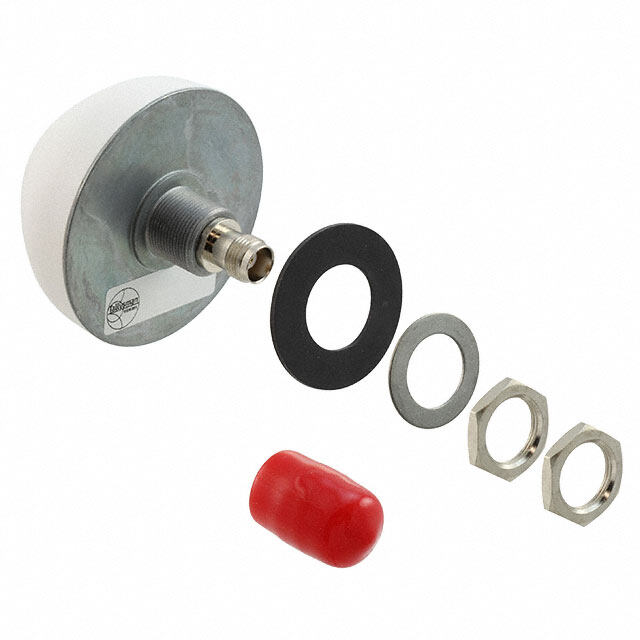
C&K品牌的MB05L1NZQD是一款旋转开关,属于精密机电元件,广泛应用于需要手动调节或模式选择的电子设备中。该型号旋转开关具有良好的电气性能和机械耐久性,适用于工业控制设备、测试测量仪器、通信设备以及医疗仪器等对可靠性要求较高的领域。

在工业自动化场景中,MB05L1NZQD可用于设备的操作面板,实现工作模式切换、参数调节或功能选择。由于其结构紧凑、手感清晰、定位准确,也常用于高端音频设备(如专业调音台、音响系统)中进行通道或音效切换。此外,在实验室仪器和数据采集系统中,该开关可提供稳定可靠的多档位控制,确保操作精准。

MB05L1NZQD具备较强的抗干扰能力和长寿命特性,适合在中等环境条件下长期运行,如温度变化不大、湿度适中的室内工业或商用环境。其设计符合国际质量标准,适用于对开关品质有较高要求的应用场合。

总之,MB05L1NZQD旋转开关主要应用于工业控制、仪器仪表、通信及专业音频设备等领域,适用于需要精确、可靠手动控制的场景。
| 参数 | 数值 |
| 品牌 | C&K Components |
| 产品目录 | 机电产品 |
| 描述 | 旋钮开关 Rotary |
| 产品分类 | |
| 产品手册 | |
| 产品图片 |
|
| rohs | 符合RoHS |
| 产品系列 | 旋钮开关,C&K Components MB05L1NZQD |
| mouser_ship_limit | 该产品可能需要其他文件才能进口到中国。 |
| 产品型号 | MB05L1NZQD |
| 产品种类 | 旋钮开关 |
| 位置数量 | 5 |
| 商标 | C&K Components |
| 安装类型 | Panel |
| 工厂包装数量 | 1 |
| 执行器 | 0.65 in Flatted |
| 指数角 | 36 deg |
| 电压额定值 | 125 VAC, 28 VDC |
| 电压额定值AC | 125 V |
| 电压额定值DC | 28 V |
| 电流额定值 | 6 A |
| 端接类型 | Solder Lug |
| 系列 | M |
| 触点形式 | DP5T |
| 触点电镀 | Silver |
| 触点类型 | Non Shorting |


- 商务部:美国ITC正式对集成电路等产品启动337调查
- 曝三星4nm工艺存在良率问题 高通将骁龙8 Gen1或转产台积电
- 太阳诱电将投资9.5亿元在常州建新厂生产MLCC 预计2023年完工
- 英特尔发布欧洲新工厂建设计划 深化IDM 2.0 战略
- 台积电先进制程称霸业界 有大客户加持明年业绩稳了
- 达到5530亿美元!SIA预计今年全球半导体销售额将创下新高
- 英特尔拟将自动驾驶子公司Mobileye上市 估值或超500亿美元
- 三星加码芯片和SET,合并消费电子和移动部门,撤换高东真等 CEO
- 三星电子宣布重大人事变动 还合并消费电子和移动部门
- 海关总署:前11个月进口集成电路产品价值2.52万亿元 增长14.8%


PDF Datasheet 数据手册内容提取
M Series Half-inch Rotary Switches Features/Benefits Typical Applications • Multi-pole and multi-positions • Test equipment • Panel and PCB mounting • Industrial equipment • Stainless steel actuator • Medical equipment • Non-shorting contacts • RoHS Compliant • IP67 (F option only) Models Available Specifications Materials CONTACT RATING: Q contact material: Carry-6 AMPS continuous. HOUSING AND BUSHING: Zinc alloy, bright zinc plated, Switch-250 mA max. @ 125 V AC or 28 DC. Non-shorting with clear chromate finish. contacts standard. See page K-16 for additional ratings. ACTUATOR: Zinc alloy, nickel plated or stainless steel. ELECTRICAL LIFE: 10,000 make-and-break cycles at 150 mA, BASE: Diallylphthalate (DAP) or melamine phenolic, with insert 125 V AC or 28 DC. molded terminals. CONTACT RESISTANCE: Below 20 mΩ typ. initial @ ROTOR: Glass filled polyester (UL 94V-0). 2-4 V DC, 100 mA, for both silver and gold plated contacts. MOVABLE CONTACTS: INSULATION RESISTANCE: 1010 Ω min. Non-shorting: Q contact material: Copper alloy, silver plated. DIELECTRIC STRENGTH: 600 Vrms min. @ sea level. See page K-16 for additional contact materials. OPERATING & STORAGE TEMPERATURE: –30ºC to 85ºC. STATIONARY CONTACT & ALL TERMINALS: Q contact material: OPERATING TORQUE: 4-7 ounces-inches typ. initial. Copper alloy, silver plated. All terminals insert molded. All terminals present regardless of number of switch positions. SOLDERABILITY: Per MIL-STD-202F method 208D, or See page K-16 for additional contact materials. EIA RS-186E method 9 (1 hour steam aging). CONTACT SPRING: Music wire, phosphate coated. STOP PIN: Stainless steel. STOP RING: Brass. NOTE: Specifications and materials listed above are for switches with standard options. For information on specific and custom switches, consult Customer Service Center. HARDWARE: Nut: Brass, nickel plated; Lockwasher: Steel, nickel plated. K Build-A-Switch To order, simply select desired option from each category and place in the appropriate box. Available options are shown and R described on pages K-14 thru K-17. For additional options not shown in catalog, consult Customer Service Center. o t a r y Switch Function MA00 SP, 10 pos., 36° MA02 SP, 2 pos., 36° Actuator & Bushing MA03 SP, 3 pos., 36° L1 .650” long, flatted MA04 SP, 4 pos., 36° L2 Screwdriver slot, flush MA05 SP, 5 pos., 36° L3 .650” long, round Short/Non-short MA06 SP, 6 pos., 36° S1 .650” long, flatted N Non-shorting contacts MA10 SP, 10 pos., 36° S2 Screwdriver slot, flush MB00 DP, 5 pos., 36° S3 .650” long, round Terminations MB03 DP, 3 pos., 36° S6 .785” long, slot Z Solder lug MB04 DP, 4 pos., 36° C PC Thru-hole Contact Material MB05 DP, 5 pos., 36° Q Silver MC00 SP, 12 pos., 30° G Gold over silver MC03 SP, 3 pos., 30° MC07 SP, 7 pos., 30° Seal MC12 SP, 12 pos., 30° D No seal MD00 DP, 6 pos., 30° F Splashproof shaft & panel seal (IP67) MD06 DP, 6 pos., 30° ME00 SP, 10 pos., 36° ME04 SP, 4 pos., 36° MF00 DP, 5 pos., 36° MG00 SP, 12 pos., 30° MH00 DP, 6 pos., 30° Dimensions are shown: Inch (mm) Specifications and dimensions subject to change www.ckswitches.com K–13
M Series Half-inch Rotary Switches SWITCH FUNCTION SP MODELS 36º INDEXING 36º INDEXING 30º INDEXING SCHEMATIC MODEL NO. MODEL NO. MODEL NO. MODEL NO. NO. WITHSTOP WITHSTOP SWITCH NO. WITHSTOP WITHSTOP SWITCH POLES PINS RINGS FUNCTION POLES PINS RINGS FUNCTION MA00 ME00 10 Positions MC00 MG00 12 Positions No Stops No Stops MA02 — 2 Positions MC03 — 3 Positions SP DP MODELS 36º INDEXING MA03 — 3 Positions SCHEMATIC MC07 — 7 Positions SP MA04 ME04 4 Positions MC12 — 12 Positions MA05 — 5 Positions MD00 MH00 6 Positions No Stops DP MA06 — 6 Positions MD06 — 6 Positions MA10 — 10 Positions MB00 MF00 5 Positions SP MODELS 30º INDEXING No Stops SCHEMATIC MB03 3 Positions DP MB04 — 4 Positions MB05 — 5 Positions DP MODELS 30º INDEXING SCHEMATIC All models with all options when ordered with S1-S6 stainless steel actuator options. NOTE: Number of positions or stops preset at factory (NOTE: MX00 models have full 360 rotation with no stops. Stop pins or stop rings supplied for user-selectable stops, see above). K All terminals present regardless of number of switch positions. Hardware is available separately, see section “Technical Data and Additional Hardware”. y ar t o R SP, 36º Indexing DP, 36º Indexing Terminal Numbers Marked Actuator Shown In Pos. 1 On Side Of Housing Part number shown: MA00L1NZQD SP, 30º Indexing DP, 30º Indexing Terminal Numbers Marked Actuator Shown In Pos. 1 On Side Of Housing Third Angle Part number shown: MC00L1NZQD Projection Dimensions are shown: Inch (mm) Specifications and dimensions subject to change www.ckswitches.com K–14
M Series Half-inch Rotary Switches ACTUATOR (ZINC ALLOY) L1 L2 .650” LONG, FLATTED SCREWDRIVER SLOT, FLUSH L3 .650” LONG, ROUND All actuators shown in pos. 1 ACTUATOR (STAINLESS STEEL) K S1 S2 .650” LONG, FLATTED SCREWDRIVER SLOT, FLUSH R o t a r y S3 S6 .650” LONG, ROUND .785” LONG, SLOT All actuators shown in pos. 1 All models when ordered with stainless steel actuators. Third Angle Projection Dimensions are shown: Inch (mm) Specifications and dimensions subject to change www.ckswitches.com K–15
M Series Half-inch Rotary Switches SHORTING/NON-SHORTING CONTACTS N NON-SHORTING CONTACTS Break-before-make TERMINATIONS Z C SOLDER LUG PC THRU-HOLE SP DP SP DP PANEL MOUNTING PC MOUNTING 36º INDEXING WITH FLATS WITHOUT FLATS SP DP 0.213 0.260 DIA (5.41) (6.59) K 0.260 DIA PC MOUNTING (6.60) 30º INDEXING SP DP y Hardware: All models, one mounting nut and lockwasher ar supplied standard. MA00 thru MD00 models: two stop pins t and adhesive mylar washer supplied. ME00 thru MH00 o models: two stop rings supplied. Hardware is available R separately, see section “Technical Data and Additional Hardware”. * Will withstand 12 in. - lbs of torque with no distortion. NOTE: Q contact material standard. Terminal numbers marked on side of housing. Actuators and schematics shown in pos. 1. All terminals insert molded. All terminals present regardless of number of switch positions. CONTACT MATERIAL OPTION CONTACT TERMINAL CODE MATERIAL PLATING RATING Q SILVER 1, 2 SILVER 2 POWER CARRY: 6 AMPS CONTINUOUS. SWITCH: 250 mA @ 125 V AC or 28 V DC. G GSOILLVDE RO V3,E 4R GOLD 4 LOORW P OLEWVEERL/DRY CIRCUIT 0C.O4 NVTAI NMUAOXU. @S. 2S0W VI TACCH o: r2 D50C mMAA @X. 1o2r,5 C VA ARCR Yo:r 62 8A MV PDSC. * Note: See Technical Data section of this catalog for RoHS compliant and compatible definition and specifications. 1 MOVABLE CONTACTS: Non-shorting: Copper alloy, silver plated. NOTE: Any models supplied with Q, G contact material are RoHS compliant. 2 STATIONARY CONTACTS & ALL TERMINALS: Copper alloy, silver plated. 3 MOVABLE CONTACTS: Non-shorting: Copper alloy, with gold plate over nickel plate, over silver plate. 4 STATIONARY CONTACTS & ALL TERMINALS: Copper alloy, with gold plate All models when ordered with S1-S6 stainless steel actuator over nickel plate over silver plate. options. Third Angle Projection Dimensions are shown: Inch (mm) Specifications and dimensions subject to change www.ckswitches.com K–16
M Series Half-inch Rotary Switches SEAL D F NO EPOXY SEAL SPLASHPROOF SHAFT AND PANEL SEAL IP67 approved Setting Stops With Stop Pins MA00, MB00, MC00 & MD00 Models Only: The number of switch positions or stops are adjustable by means of stop pins provided with each switch. Switches are normally shipped with stop pins and hardware in bulk, not installed. Without stop pins, switches have full 360º rotation and no stops. Note that all two pole models begin to repeat when actuated 180º or more. To set stops, refer to figures 1 & 2. Orient switch so that terminal no. 1 is as shown. Turn actuator to position 1, using flats on bushing and terminal no. 1 as reference. Install CCW stop pin in hole designated ‘X’. Install second stop pin in hole number corresponding to the number of positions desired. Note that two pole models will begin to repeat when actuated 180º or more. To retain stop pins, use adhesive mylar washer included; see figure 3. All models except MX00 models have number of switch positions or stops pre-set at factory and are not adjustable. Hardware: Two stop pins, mounting nut, and lockwasher supplied standard. P/N 537100000 K 36º Indexing Models 30º Indexing Models Top View Top View P/N 537202000 R Fig. 1 Fig. 2 Fig. 3 o t a Setting Stops With Stop Rings r y ME00, MF00, MG00 & MH00 Models Only: The number of switch positions or stops are adjustable by means of stop rings provided with each switch. These models are normally shipped with stop rings and hardware in bulk, not installed. Without stop rings, switches have full 360º rotation and no stops. Note that all two pole models begin to repeat when actuated 180º or more. To set stops refer to figures 4 & 5. Orient switch so that terminal no. 1 is as shown. Turn actuator to pos. 1 using flats on bush- ing and terminal no. 1 as reference. See figure 6 and install inner stop ring with short tab in hole designated ‘X’. Install outer stop ring with long tab in hole number corresponding to the number of positions desired. Note that all two pole models begin to repeat when actuated 180º or more. Use mounting nut and lockwasher to retain stop rings. All MEXX, MFXX, MGXX & MHXX Models (Except MX00 models): Number of switch positions or stops are preset at factory, but are user adjustable. Hardware: Two stop rings, mounting nut and lockwasher supplied standard. 36º Indexing Models 30º Indexing Models Top View Top View Fig. 4 Fig. 5 Fig. 6 Dimensions are shown: Inch (mm) Specifications and dimensions subject to change www.ckswitches.com K–17
Mouser Electronics Authorized Distributor Click to View Pricing, Inventory, Delivery & Lifecycle Information: C &K Switches: MA05L1NZQD MA00L3NZQD MG00L1NCQD MA00L1NCQD MF00L1NZQD MB00S2NZGF MG00L1NZQD MC00L1NCQD MA04S1NZQF MA05S1NZGF MA05L2NCQD MB03L1NZQF MB05S1NZQD MB03L1NZQD MA04S6NCGD MB00L2NZQD MD00L1NZQF MF00L1NZGD ME00L1NCQD MB00L1NZQD MD00L1NZQD MH00L1NZQD MA00L1NZQD ME00L1NZQD MB00L1NCQD MA00L1NCGF MA00L1NCQF MA00L1NZGD MA00L2NCQD MA00L3NCGD MA00L3NCGF MA00L3NCQD MA00L3NZGD MA00S1NCGF MA00S1NCQD MA00S1NZGD MA00S1NZQD MA00S2NCGD MA00S3NCQD MA00S3NCQF MA00S3NZGF MA00S3NZQD MA00S3NZQF MA02L2NZQD MA02L3NZQD MA02S1NZGD MA02S1NZGF MA02S3NCQD MA02S3NZQD MA03L1NCGF MA03L1NCQD MA03L1NZGD MA03L1NZQD MA03S1NCGD MA03S1NZGF MA03S3NZQD MA04L1NCGD MA04L1NCQD MA04L1NZQD MA04L2NCQD MA04L2NZGF MA04L2NZQD MA04S1NCGD MA04S1NCGF MA04S1NZGF MA04S2NCGF MA04S3NCQD MA04S3NZGD MA04S3NZQD MA04S3NZQF MA05L1NCGD MA05L1NCQD MA05L1NZGD MA05L1NZGF MA05S1NCGF MA05S1NCQD MA05S3NCGF MA06L1NZGF MA06L1NZQD MA06S1NCGD MA06S2NCGD MA06S2NZQF MA06S3NCQD MA10L1NCQF MA10L3NCGD MA10L3NCQD MA10S1NCGD MA10S2NCGD MA10S3NCQD MA10S3NCQF MA10S3NZQD MA10S6NCGD MB00L1NCGD MB00L1NZGD MB00L1NZQF MB00L3NCGD MB00L3NCQD MB00S1NCQD MB00S3NZQD MB03L1NCQD