ICGOO在线商城 > 集成电路(IC) > PMIC - 栅极驱动器 > M57959L
- 型号: M57959L
- 制造商: POWEREX
- 库位|库存: xxxx|xxxx
- 要求:
| 数量阶梯 | 香港交货 | 国内含税 |
| +xxxx | $xxxx | ¥xxxx |
查看当月历史价格
查看今年历史价格
M57959L产品简介:
ICGOO电子元器件商城为您提供M57959L由POWEREX设计生产,在icgoo商城现货销售,并且可以通过原厂、代理商等渠道进行代购。 M57959L价格参考。POWEREXM57959L封装/规格:PMIC - 栅极驱动器, Low-Side Gate Driver IC Non-Inverting Module。您可以下载M57959L参考资料、Datasheet数据手册功能说明书,资料中有M57959L 详细功能的应用电路图电压和使用方法及教程。
Powerex Inc.的M57959L是一款PMIC(电源管理集成电路)栅极驱动器,主要应用于需要高效功率控制和转换的场景。其典型应用场景包括但不限于以下几种:

1. 电动车辆(EV)和混合动力车辆(HEV):M57959L能够为电动汽车中的电机驱动系统提供高效的栅极驱动信号,确保电机在不同工况下都能获得稳定的电源支持。它还能与逆变器配合,实现对电池能量的有效管理和分配,提高整车的能效。

2. 工业自动化设备:在工业自动化领域,M57959L可用于驱动各种类型的功率器件(如IGBT、MOSFET等),以实现对电机、伺服系统和其他大功率负载的精确控制。其快速响应特性和低延迟性能有助于提升系统的整体效率和稳定性。

3. 不间断电源(UPS)系统:M57959L可以用于UPS系统中的逆变电路,确保在市电中断时能够迅速切换到备用电源,并为关键负载提供持续稳定的电力供应。此外,它还可以帮助优化电池充电过程,延长电池寿命。

4. 太阳能逆变器:在光伏发电系统中,M57959L可以作为栅极驱动器,用于将直流电转换为交流电,从而将太阳能板产生的电能高效地输送到电网或本地负载。它的高集成度和可靠性使得整个系统更加紧凑且易于维护。

5. 消费电子产品:对于一些高性能消费电子产品(如笔记本电脑、平板电脑等),M57959L可以用于内部电源管理系统,确保各个组件得到适当的工作电压和电流,同时降低功耗并延长电池续航时间。

总之,M57959L凭借其出色的性能和广泛的应用范围,在众多涉及功率控制和转换的领域中发挥着重要作用。
| 参数 | 数值 |
| 产品目录 | 集成电路 (IC) |
| 描述 | IC GATE DRVR FOR IGBT MOD |
| 产品分类 | PMIC - MOSFET,电桥驱动器 - 外部开关 |
| 品牌 | Powerex Inc |
| 数据手册 | |
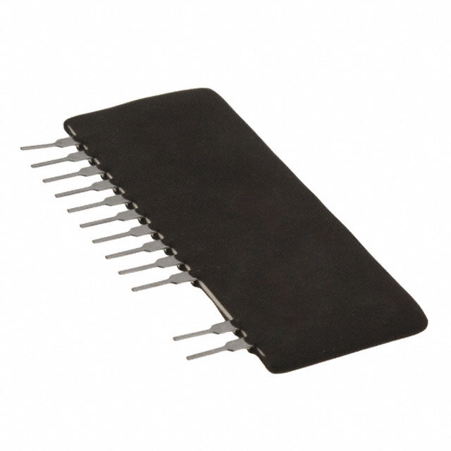
| 产品图片 |
|
| 产品型号 | M57959L |
| rohs | 无铅 / 符合限制有害物质指令(RoHS)规范要求 |
| 产品系列 | - |
| 供应商器件封装 | 模块 |
| 其它名称 | 835-1106 |
| 包装 | 散装 |
| 安装类型 | 通孔 |
| 封装/外壳 | 14-SIP(12 引线) |
| 工作温度 | -20°C ~ 60°C |
| 延迟时间 | 800ns |
| 标准包装 | 13 |
| 电压-电源 | 14 V ~ 15 V |
| 电流-峰值 | 2A |
| 输入类型 | 非反相 |
| 输出数 | 1 |
| 配置 | - |
| 配置数 | 1 |
| 高压侧电压-最大值(自举) | 1200V |


- 商务部:美国ITC正式对集成电路等产品启动337调查
- 曝三星4nm工艺存在良率问题 高通将骁龙8 Gen1或转产台积电
- 太阳诱电将投资9.5亿元在常州建新厂生产MLCC 预计2023年完工
- 英特尔发布欧洲新工厂建设计划 深化IDM 2.0 战略
- 台积电先进制程称霸业界 有大客户加持明年业绩稳了
- 达到5530亿美元!SIA预计今年全球半导体销售额将创下新高
- 英特尔拟将自动驾驶子公司Mobileye上市 估值或超500亿美元
- 三星加码芯片和SET,合并消费电子和移动部门,撤换高东真等 CEO
- 三星电子宣布重大人事变动 还合并消费电子和移动部门
- 海关总署:前11个月进口集成电路产品价值2.52万亿元 增长14.8%
PDF Datasheet 数据手册内容提取
M57959L Powerex, Inc., 200 Hillis Street, Youngwood, Pennsylvania 15697-1800 (724) 925-7272 Gate Driver Hybrid Integrated Circuit Block Diagram For Driving IGBT Modules 4 VCC Description: 14 DCeirtceucitt 1 Detect Pin M57959L is a hybrid integrated 185V circuit designed for driving n-channel Timer and Reset Circuit IGBT modules in any gate amplifier Interface 5 VOUT application. This device operates as an isolation amplifier for these – modules and provides the required 13 GateC Sirhcuutidtown 8 Fault Output electrical isolation between the in- Opto-Coupler 6 VEE put and output with an opto-coupler. Short circuit protection is provided Outline Drawing by a built in desaturation detector. Dimensions in mm 43.0 A fault signal is provided if the short circuit protection is activated. 22.0 Features: h Built in high CMRR opto- 4.5 – 1.5 coupler (V : Typical CMR 30kV/ms, Min. 15kV/ms) 0.55 – 0.2 0.35 – 0.2 2.54 3.5 11.0 h Electrical Isolation between 5.5 1 2.54 · 13 = 33.02 14 5.5 8.5 input and output with opto- couplers (V = 2500, iso Test Circuit V for 1 min.) RMS R h TTL compatible input interface 4.7 kV VIN h Two supply drive topology 8 1 D1 h Built in short circuit protection 5 DZ1 30RV VOUT tr tf 90% circuit with a pin for fault output ext V 4 IN + + 47m F VCC 0 10% Application: 14 + + To drive IGBT modules for inverter, 13 6 47m F VVEE = 15 V tPLH tPHL AC Servo systems, UPS, CVCF TTL, etc. CC inverter, and welding applications. VIN = 5V VEE = 10V R = RECOMMENDED ext VALUE Recommended Modules: V = 600V Series CES (up to 200A Class) V = 1200V Series CES (up to 100A Class) V = 1400V Series CES (up to 100A Class) 149
Powerex, Inc., 200 Hillis Street, Youngwood, Pennsylvania 15697-1800 (724) 925-7272 M57959L Hybrid IC for IGBT Gate Driver Absolute Maximum Ratings, T ~ 20(cid:176) C to 70(cid:176) C unless otherwise specified a Item Symbol Test Conditions Limit Units Supply Voltage* VCC DC 18 Volts VEE DC -15 Volts Input Voltage VI -1 ~ 7 Volts Output Voltage VO Output Voltage “H” VCC Volts Output Current IOHP Pulse Width 2m s, f = 20kHz -2 Amperes IOLP Pulse Width 2m s, f = 20kHz 2 Amperes Output Current IOH f = 20kHz, 50% Duty Cycle 0.2 Amperes Isolation Voltage VRMS Sinewave Voltage 60kHz, 1 min. 2500 Volts Junction Temperature Tj 85 (cid:176) C Operating Temperature Topg (Differs from H/C Condition) -20 ~ 60 (cid:176) C Storage Temperature Tstg -25 ~ 100 (cid:176) C Fault Output Current IFO 20 mA Input Voltage VR1 50 Volts *20 Volts £ VCC + VEE £ 28 Volts Electrical Characteristics, T = 25(cid:176) C, V = 15V, -V = 10V unless otherwise specified a CC EE Characteristics Symbol Test conditions Min. Typ. Max. Unit Supply Voltage VCC Recommended Range 14 15 — Volts VEE Recommended Range -7 — -10 Volts Pull-up Voltage on Input Side VIN Recommended Range 4.75 5.00 5.25 Volts “H” Input Current IIH VIN = 5V, R = 185W — 16 — mA “H” Output Voltage VOH 13 14 — Volts “L” Output Voltage VOL -8 -9 — Volts Internal Power Dissipation PD f = 20kHz, — 0.86 — Watts Module 200A, 600V IGBT “L-H” Propagation Time tPLH VI = 0 to 4V, Tj – 85(cid:176) C — 0.8 1.5 m s “L-H” Rise Time tr VI = 0 to 4V, Tj – 85(cid:176) C — 0.5 1.0 m s “H-L” Propagation Time tPHL VI = 0 to 4V, Tj – 85(cid:176) C — 1.0 1.5 m s “H-L” Rise Time tr VI = 0 to 4V, Tj – 85(cid:176) C — 0.3 0.6 m s Reset Time of Protection tRESET 1 — 2 ms Fault Output Current IFO — 5 — mA SC Voltage VSC 15 — — Volts 150

 Datasheet下载


