ICGOO在线商城 > LDBAA2220JC5N0
.jpg)
 Datasheet下载
- 型号: LDBAA2220JC5N0
- 制造商: Kemet
- 库位|库存: xxxx|xxxx
- 要求:
| 数量阶梯 | 香港交货 | 国内含税 |
| +xxxx | $xxxx | ¥xxxx |
查看当月历史价格
查看今年历史价格
LDBAA2220JC5N0产品简介:
ICGOO电子元器件商城为您提供LDBAA2220JC5N0由Kemet设计生产,在icgoo商城现货销售,并且可以通过原厂、代理商等渠道进行代购。 提供LDBAA2220JC5N0价格参考以及KemetLDBAA2220JC5N0封装/规格参数等产品信息。 你可以下载LDBAA2220JC5N0参考资料、Datasheet数据手册功能说明书, 资料中有LDBAA2220JC5N0详细功能的应用电路图电压和使用方法及教程。
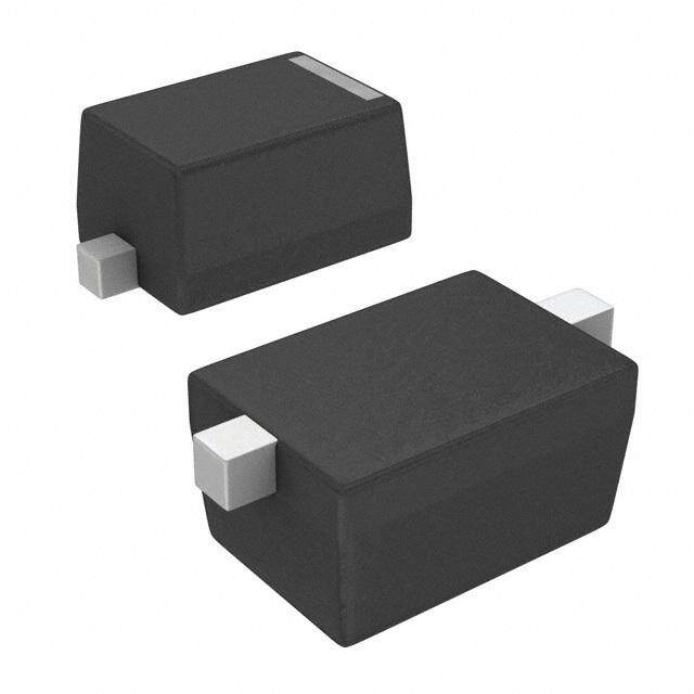
KEMET LDBAA2220JC5N0 是一款高性能金属化聚丙烯(MKP)薄膜电容器,属于LDBA系列,额定电压为630 VDC(或400 VAC),标称容量为2.2 nF(2200 pF),容差±5%,采用径向引线封装,具有低ESR、低电感、高纹波电流承受能力及优异的自愈特性。

其典型应用场景包括:
1. EMI/RFI滤波:常用于开关电源(SMPS)、变频器、LED驱动器等设备的输入/输出端,抑制高频传导干扰;
2. 缓冲与吸收电路:在IGBT/MOSFET功率开关回路中用作RC吸收网络(Snubber),吸收开关瞬态尖峰电压,保护半导体器件;
3. 谐振与定时电路:适用于高频谐振腔、LLC谐振变换器中的谐振电容,或对温漂和老化稳定性要求较高的精密定时场合;
4. 工业控制与新能源系统:如光伏逆变器、储能变流器(PCS)中DC侧高频滤波与保护环节。

该型号符合UL/ENEC安规认证,具备AEC-Q200(部分批次)兼容性,工作温度范围宽(–55°C 至 +105°C),长期可靠性高,适合严苛工业与车载电子环境。注意:实际选型需结合具体电路的电压应力、dv/dt、纹波电流及安全间距要求进行验证。
| 参数 | 数值 |
| 产品目录 | |
| 描述 | CAP FILM 0.022UF 16VDC 1206 |
| ESR(等效串联电阻) | - |
| 产品分类 | |
| 品牌 | Kemet |
| 数据手册 | http://capacitoredge.kemet.com/capedge2/DataSheet?pn=LDBAA2220JC5N0点击此处下载产品Datasheet |
| 产品图片 |
|
| 产品型号 | LDBAA2220JC5N0 |
| rohs | 无铅 / 符合限制有害物质指令(RoHS)规范要求 |
| 产品系列 | LDB |
| 介电材料 | 聚苯硫醚(PPS) |
| 其它名称 | 399-6382-6 |
| 包装 | Digi-Reel® |
| 大小/尺寸 | 0.130" 长 x 0.067" 宽(3.30mm x 1.70mm) |
| 安装类型 | 表面贴装 |
| 容差 | ±5% |
| 封装/外壳 | 1206(3216 公制) |
| 工作温度 | -55°C ~ 125°C |
| 应用 | 通用 |
| 引线间距 | - |
| 标准包装 | 1 |
| 特性 | - |
| 电容 | 0.022µF |
| 端接 | 焊盘 |
| 额定电压-AC | - |
| 额定电压-DC | 16V |
| 高度-安装(最大值) | 0.043"(1.10mm) |


- 商务部:美国ITC正式对集成电路等产品启动337调查
- 曝三星4nm工艺存在良率问题 高通将骁龙8 Gen1或转产台积电
- 太阳诱电将投资9.5亿元在常州建新厂生产MLCC 预计2023年完工
- 英特尔发布欧洲新工厂建设计划 深化IDM 2.0 战略
- 台积电先进制程称霸业界 有大客户加持明年业绩稳了
- 达到5530亿美元!SIA预计今年全球半导体销售额将创下新高
- 英特尔拟将自动驾驶子公司Mobileye上市 估值或超500亿美元
- 三星加码芯片和SET,合并消费电子和移动部门,撤换高东真等 CEO
- 三星电子宣布重大人事变动 还合并消费电子和移动部门
- 海关总署:前11个月进口集成电路产品价值2.52万亿元 增长14.8%
PDF Datasheet 数据手册内容提取
Surface Mount Metallized PPS Film Capacitor LDB, Unencapsulated Stacked Chip, Size 1206 – 1812, 16 VDC and 50 VDC Overview Applications Polyphenylene sulphide (PPS) film capacitor for surface Typical applications include timing, filtering, and use as mounting. a memory capacitor. The LDB Series is designed for high stability, accuracy, and temperature. Benefits • Rated voltage: 16 – 50 VDC • Capacitance range: 0.0033 – 0.1µF • EIA Size 1206 – 1812 • Capacitance tolerance: ±2%, ±5% • Climatic category: 55/125/56 • RoHS compliance and lead-free terminations • Operating temperature range of −55°C to +125°C Part Number System LDB A A 2120 G C 5 N 0 Rated Voltage Capacitance Capacitance Series Size Code Dielectric Version Packaging Internal Use (VDC) Code (pF) Tolerance Metallized PPS A = 16 See Dimension Digits two – G = ±2% C = PPS 5 = Standard See Ordering 0 (Standard) C = 50 Table four indicate J = ±5% Options Table the first three digits of the capacitance value. First digit indicates the number of zeros to be added. One world. One KEMET © KEMET Electronics Corporation • KEMET Tower • One East Broward Boulevard F3082_LDB • 11/22/2019 1 Fort Lauderdale, FL 33301 USA • 954-766-2800 • www.kemet.com
Surface Mount Metallized PPS Film Capacitors LDB, Unencapsulated Stacked Chip, Size 1206 – 1812, 16 VDC and 50 VDC Ordering Options Table Packaging Packaging Type Code Standard Packaging Options Tape & Reel (Standard Reel) N Dimensions – Millimeters Chip Size W H L B Size Code (EIA) Nominal Tolerance (Maximum) Nominal Tolerance Nominal Tolerance A 1206 1.7 ±0.2 3.3 +0.3/−0.1 0.5 +0.5/−0.3 B 1210 2.5 ±0.3 See Part Number Table 3.3 +0.3/−0.1 0.5 +0.5/−0.3 C 1812 3.3 ±0.3 4.7 +0.3/−0.2 0.5 +0.5/−0.3 © KEMET Electronics Corporation • KEMET Tower • One East Broward Boulevard F3082_LDB • 11/22/2019 2 Fort Lauderdale, FL 33301 USA • 954-766-2800 • www.kemet.com
Surface Mount Metallized PPS Film Capacitors LDB, Unencapsulated Stacked Chip, Size 1206 – 1812, 16 VDC and 50 VDC Performance Characteristics Rated Voltage (VDC) 16 50 Capacitance Range (μF) 0.012 – 0.1 0.0033 – 0.1 Chip Size (EIA) 1206 – 1812 Capacitance Values E12 series Capacitance Tolerance ±2%, ±5% Category Temperature Range −55°C to +125°C Rated Temperature +105°C V (category voltage) = V (rated voltage) up to 105°C. V is decreased Voltage Derating C R C with 1.25%/°C from +105°C to +125°C Climatic Category 55/125/56 Maximum 1% after a 2 year storage period at a temperature of +10°C Capacitance Drift to +40°C and a relative humidity of 40% to 60% Failure rate ≤ 1 FIT, T = +40°C, V = 0.5 x V R Reliability 1 FIT = 10-9 failures / (components * hours) (Reference MIL-HDBK-217) Failure criteria: open or short circuit, cap. change > 10%, DF 2 times the catalog limits, IR < 0.005 x initial limit Measured at +25°C ±5°C Between Terminals 3,000 MΩ Insulation Resistance Charging time: 1 minute Charging voltage: 10 VDC for V = 16 VDC R 50 VDC for V = 50 VDC R Maximum Values at 25°C ±5°C Dissipation Factor 1 kHz 0.6% Surge Voltage Test 1.75 x V (5 seconds; T = 25 ± 5°C) R © KEMET Electronics Corporation • KEMET Tower • One East Broward Boulevard F3082_LDB • 11/22/2019 3 Fort Lauderdale, FL 33301 USA • 954-766-2800 • www.kemet.com
Surface Mount Metallized PPS Film Capacitors LDB, Unencapsulated Stacked Chip, Size 1206 – 1812, 16 VDC and 50 VDC PPS Dielectric Typical Temperature Graphs PPS Dielectric Typical Frequency Graphs Capacitance vs. Frequency Capacitance vs. Temperature 2.0 (f = 1 kHz) 1.5 1.0 1.0 %]0.5 0.5 C [0.0 C/ %] 0.0 ∆ −0.5 C [ −1.0 / ∆ C −0.5 −1.5 −2.0 0.1 1 10 100 1,000 −1.0 f [kHZ] −1.5 Dissipation Factor vs. Frequency −60 −40 −20 0 20 40 60 80 100 120 140 100 Temperature [°C] 80 0.1 µF −40 60 1 x Dissipation Factor vs. Temperature g δ 40 t (f = 1 kHz) 20 50 10 nF 0 0.1 1 10 100 1,000 40 f [kHZ] 0−4 30 1 Equivalent Series Resisteance vs. Frequency x gδ 20 1E+2 t 10 1E+1 Ω] 0 R [1E+0 10 nF −60 −40 −20 0 20 40 60 80 100 120 140 S E 0.1 µF Temperature [°C] 1E−1 1E−2 Insulation Resistance vs. Temperature 0.1 1 10 100 1,000 f [kHZ] 1E+7 PEN and PPS Impedance vs. Frequency 10 1E+6 Ω] M 1 R [ Ω] I 1E+5 Z| [ | 0.1 1E+4 1.0 µF 0.1 µF 0.01 µF −60 −40 −20 0 20 40 60 80 100 120 140 0.01 0.1 1 10 100 Temperature [°C] f [MHZ] Note: Measurements performed at T = 25±5°C © KEMET Electronics Corporation • KEMET Tower • One East Broward Boulevard F3082_LDB • 11/22/2019 4 Fort Lauderdale, FL 33301 USA • 954-766-2800 • www.kemet.com
Surface Mount Metallized PPS Film Capacitors LDB, Unencapsulated Stacked Chip, Size 1206 – 1812, 16 VDC and 50 VDC Environmental Test Data Damp Heat, Steady State Reflow Test Conditions Test Conditions See Solder Process Temperature +40°C ±2°C Performance Relative Humidity (RH) 93% ±2% Capacitance Change |∆ C/C| ≤ 3% Test Duration 56 days DF Change (∆tgδ) ≤ 50 x 10−4 at 1 kHz Performance Insulation Resistance ≥ limit value Capacitance Change |∆ C/C| ≤ 5% No Mechanical Damage DF Change (∆tgδ) ≤ 30 x 10−4 at 1 kHz Bending Insulation Resistance ≥ 50% of limit value Test Conditions Endurance Deflection 1 – 6 mm Performance Test Conditions Capacitance Change |∆ C/C| ≤ 1% Temperature 125°C ±2°C No visible damage on the terminations Test Duration 2,000 hours (peeling) neither on the body (cracking) Voltage Applied 1.25 x V C Performance Capacitance Change |∆ C/C| ≤ 3% DF Change (∆tgδ) ≤ 30 x 10−4 at 1 kHz Insulation Resistance ≥ 50% of limit value Rapid Change of Temperature Test Conditions 1 hour at −55°C, Temperature 1 hour at +125°C Number of Cycles 1,000 Performance Capacitance Change |∆ C/C| ≤ 3% DF Change (∆tgδ) ≤ 50 x 10−4 at 1 kHz Insulation Resistance ≥ limit value No Mechanical Damage Environmental Compliance All KEMET surface mount capacitors are RoHS Compliant. © KEMET Electronics Corporation • KEMET Tower • One East Broward Boulevard F3082_LDB • 11/22/2019 5 Fort Lauderdale, FL 33301 USA • 954-766-2800 • www.kemet.com
Surface Mount Metallized PPS Film Capacitors LDB, Unencapsulated Stacked Chip, Size 1206 – 1812, 16 VDC and 50 VDC Table 1 – Ratings & Part Number Reference Capacitance Dimensions in mm New KEMET Legacy Part VDC Size Code Chip Size Value (µF) W H (max) L Part Number Number 16 0.012 A 1.7 1.1 3.3 1206 DBAA2120(1)C5N0 LDBAA2120(1)C5N0 16 0.015 A 1.7 1.1 3.3 1206 DBAA2150(1)C5N0 LDBAA2150(1)C5N0 16 0.018 A 1.7 1.1 3.3 1206 DBAA2180(1)C5N0 LDBAA2180(1)C5N0 16 0.022 A 1.7 1.1 3.3 1206 DBAA2220(1)C5N0 LDBAA2220(1)C5N0 16 0.027 A 1.7 1.1 3.3 1206 DBAA2270(1)C5N0 LDBAA2270(1)C5N0 16 0.033 A 1.7 1.1 3.3 1206 DBAA2330(1)C5N0 LDBAA2330(1)C5N0 16 0.039 A 1.7 1.2 3.3 1206 DBAA2390(1)C5N0 LDBAA2390(1)C5N0 16 0.047 A 1.7 1.3 3.3 1206 DBAA2470(1)C5N0 LDBAA2470(1)C5N0 16 0.056 B 2.5 1.7 3.3 1210 DBAB2560(1)C5N0 LDBAB2560(1)C5N0 16 0.068 B 2.5 1.7 3.3 1210 DBAB2680(1)C5N0 LDBAB2680(1)C5N0 16 0.082 B 2.5 1.7 3.3 1210 DBAB2820(1)C5N0 LDBAB2820(1)C5N0 16 0.10 B 2.5 2.0 3.3 1210 DBAB3100(1)C5N0 LDBAB3100(1)C5N0 50 0.0033 A 1.7 1.1 3.3 1206 DBCA1330(1)C5N0 LDBCA1330(1)C5N0 50 0.0039 A 1.7 1.1 3.3 1206 DBCA1390(1)C5N0 LDBCA1390(1)C5N0 50 0.0047 A 1.7 1.1 3.3 1206 DBCA1470(1)C5N0 LDBCA1470(1)C5N0 50 0.0056 A 1.7 1.1 3.3 1206 DBCA1560(1)C5N0 LDBCA1560(1)C5N0 50 0.0068 A 1.7 1.1 3.3 1206 DBCA1680(1)C5N0 LDBCA1680(1)C5N0 50 0.0082 A 1.7 1.1 3.3 1206 DBCA1820(1)C5N0 LDBCA1820(1)C5N0 50 0.010 A 1.7 1.1 3.3 1206 DBCA2100(1)C5N0 LDBCA2100(1)C5N0 50 0.012 A 1.7 1.1 3.3 1206 DBCA2120(1)C5N0 LDBCA2120(1)C5N0 50 0.015 B 2.5 1.4 3.3 1210 DBCB2150(1)C5N0 LDBCB2150(1)C5N0 50 0.018 B 2.5 1.5 3.3 1210 DBCB2180(1)C5N0 LDBCB2180(1)C5N0 50 0.022 B 2.5 1.5 3.3 1210 DBCB2220(1)C5N0 LDBCB2220(1)C5N0 50 0.027 B 2.5 1.5 3.3 1210 DBCB2270(1)C5N0 LDBCB2270(1)C5N0 50 0.033 B 2.5 1.7 3.3 1210 DBCB2330(1)C5N0 LDBCB2330(1)C5N0 50 0.039 B 2.5 1.9 3.3 1210 DBCB2390(1)C5N0 LDBCB2390(1)C5N0 50 0.047 B 2.5 2.3 3.3 1210 DBCB2470(1)C5N0 LDBCB2470(1)C5N0 50 0.056 C 3.3 1.7 4.7 1812 DBCC2560(1)C5N0 LDBCC2560(1)C5N0 50 0.068 C 3.3 1.7 4.7 1812 DBCC2680(1)C5N0 LDBCC2680(1)C5N0 50 0.082 C 3.3 1.7 4.7 1812 DBCC2820(1)C5N0 LDBCC2820(1)C5N0 50 0.10 C 3.3 2.0 4.7 1812 DBCC3100(1)C5N0 LDBCC3100(1)C5N0 Capacitance W H L New KEMET VDC Size Code Chip Size Legacy Part Number Value (µF) (mm) (mm) (mm) Part Number (1) G = ±2%, J = ±5%. © KEMET Electronics Corporation • KEMET Tower • One East Broward Boulevard F3082_LDB • 11/22/2019 6 Fort Lauderdale, FL 33301 USA • 954-766-2800 • www.kemet.com
Surface Mount Metallized PPS Film Capacitors LDB, Unencapsulated Stacked Chip, Size 1206 – 1812, 16 VDC and 50 VDC Soldering Process Reflow Recommendations Reflow Temperature Profile Temperature Preheating T max Maximum Preheating Time 180 seconds T −5°C max ∆T 5 Minimum Temperature 150°C 217°C Maximum Temperature 200°C Preheating ∆T217 30 seconds (T ≤ 250°C) Maximum Time within T and max max T – 5°C (∆T) 10 seconds max 5 (250 °C < T ≤ 260°C) max Linear profiles are also allowed (if in line with the reflow recommendations) Time Maximum Time Over 217°C 150 seconds (∆T ) 217 3°C/seconds (heating) Maximum Temperature Ramp Rate 6°C/seconds (cooling) Second reflow If two reflow processes are needed, be sure that before the second reflow, the temperature on the capacitor’s surface is lower than 50°C. * Maximum Temperature on the component's body (T ): = 260 °C. max Landing A B C D Dimensions in mm Size A B C D 1206 1.5 1.1 2.3 4.5 1210 2.3 1.1 2.3 4.5 1812 3.0 1.7 3.1 6.5 These landing area dimensions have the aim of taking full advantage of the new RoHS 6 terminations design. We suggest to use a Sn/Ag/Cu solder paste (suggested thickness: 0.10 – 0.15 mm). If a NOT Lead Free solder paste is used, a minimum peak temperature of 210°C on the component’s body is suggested. © KEMET Electronics Corporation • KEMET Tower • One East Broward Boulevard F3082_LDB • 11/22/2019 7 Fort Lauderdale, FL 33301 USA • 954-766-2800 • www.kemet.com
Surface Mount Metallized PPS Film Capacitors LDB, Unencapsulated Stacked Chip, Size 1206 – 1812, 16 VDC and 50 VDC Flux/Cleaning/Storage and Moisture B Flux suggestions KEMET suggests to use a no-clean flux with a halogen content lower than 0.1%. A C Cleaning suggestions To clean the PCB assembly, KEMET recommends using a suitable solvent like Isopropyl alcohol, deionized water, or neutral pH detergents. Aggressive solvents shall not be used. C For any different cleaning solvent used, please contact KEMET Technical Services to A analyze the potential impact on KEMET products. Fig. 1 B Storage and moisture recommendations KEMET SMD Film Capacitors are supplied in a MBB (Moisture Barrier Bag) Class 1. We can guarantee a 24 month shelf life (temperature ≤ 40°C/relative humidity ≤ 90%). After the MBB has been opened, components may stay in areas with controlled temperature and humidity (temperature ≤ 30°C/relative humidity ≤ 60%) for 168 hours [MSL 3]. For longer periods of time and/or higher temperature and/or higher relative humidity values, it is absolutely necessary to protect the components against humidity. If the reel inside the MBB is partially used, KEMET recommends to re-use the same MBB or to avoid areas without controlled temperature and humidity (see above). If the above conditions are not respected, components require a baking (minimum time: 48 hours at 55 ±5°C) before the reflow. Manual assembly recommendations If PCBs are assembled manually, care must be taken to avoid any mechanical damage to the components. Our recommendations are the following (see Fig. 1): 1) When using tweezers, the components should be gripped across the two terminations (A) 2) Avoid any contact with the two cutting surfaces (C) 3) A vacuum pen is recommended on the top and bottom surfaces (B) © KEMET Electronics Corporation • KEMET Tower • One East Broward Boulevard F3082_LDB • 11/22/2019 8 Fort Lauderdale, FL 33301 USA • 954-766-2800 • www.kemet.com
Surface Mount Metallized PPS Film Capacitors LDB, Unencapsulated Stacked Chip, Size 1206 – 1812, 16 VDC and 50 VDC Flux/Cleaning/Storage and Moisture cont. Manual soldering recommendations LDE and LDB series have been designed for Surface Mount Technology, pick-and- place machines, and reflow soldering systems. Issues may occur using a manual soldering iron because the typical temperature for manual soldering is appoximately 350°C. Therefore please pay careful attention: • Never touch the capacitor body with the sodering iron but rather touch the soldering iron and the end termination with the tin wire edge (see Figure 2) • If the soldering iron is equipped with a temperature controlling device, set the temperature to 250 ±3°C and proceed as per Figure 2 (the maximum soldering time, on both terminations, is 5 seconds) • A soldering iron that is NOT equipped with a temperature controlling device is not an ideal situation and operator experience is extremely important in this case. If you have a soldering iron that does not have a temperature controlling device, please use the following practical suggestions: 1) Proceed as per Figure 2 2) As soon as the tin wire starts melting, move the soldering iron away as quickly as possible 3) Wait a few seconds and check that the soldering joint has been properly created • If the soldering iron is equipped with a hot air flow device, set the hot air temperature to 250 ±3°C and do not send the hot air directly onto the capacitor plastic body. In this situation, the operator’s experience is very important. • In any case, avoid mass-mounting SMD Film Capacitors manually. Tin Wire Fig. 2 Landing Area SMD Film Capacitor Soldering Iron PCB Packaging Quantities Chip Size (EIA) Height (mm) Reel Chip Size (EIA) Height (mm) Reel 1206 1.1 3,000 1210 1.9 2,250 1206 1.2 3,000 1210 2.0 2,250 1206 1.3 3,000 1210 2.3 2,250 1210 1.4 2,250 1812 1.7 4,000 1210 1.5 2,250 1812 2.0 3,000 1210 1.7 2,250 © KEMET Electronics Corporation • KEMET Tower • One East Broward Boulevard F3082_LDB • 11/22/2019 9 Fort Lauderdale, FL 33301 USA • 954-766-2800 • www.kemet.com
Surface Mount Metallized PPS Film Capacitors LDB, Unencapsulated Stacked Chip, Size 1206 – 1812, 16 VDC and 50 VDC Production Process Basic Suggestions In case of: Typical cause Typical solution Landing area dimensions See landing areas suggestions, page 9 Solder paste quality See solder paste suggestions, page 9 Not-uniform solder paste thickness Set the dispensing solder paste machine properly No solder joint on one on the landing areas end termination Wrong position of the capacitor Set the pick and place machine properly on the landing areas Thermal profile temperature See reflow recommendations, page 7 Bad temperature distribution Check the reflow oven temperature in the reflow oven distribution and variations" Landing area dimensions See landing areas suggestions, page 9 Solder paste quality See solder paste suggestions, page 9 No solder paste on the landing areas Set the dispensing solder paste machine properly No solder joint on both end termination Thermal profile temperature See reflow recommendations, page 7 Bad temperature distribution Check the reflow oven temperature in the reflow oven distribution and variations Oxidated end terminations See moisture recommendations, page 8 Too long time over 217°C See reflow recommendations, page 7 Too long time within T and T −5°C See reflow recommendations, page 7 Capacitor's body max max mechanical deformation Too high temperature ramp rate See reflow recommendations, page 7 Capacitor damaged by a soldering iron See manual soldering recommendations, page 8 Too long time over 217°C See reflow recommendations, page 7 Too long time within T and T −5°C See reflow recommendations, page 7 max max Capacitance drop (up to 20%) Too high temperature ramp rate See reflow recommendations, page 7 Capacitor damaged by a soldering iron See manual soldering recommendations, page 8 Capacitance drop (over 20%) Capacitor damaged by a soldering iron See manual soldering recommendations, page 8 Note: Small fissures on the capacitor’s cutting surface are actually slight detachments of two adjacent metallized film layers and have to be considered only as an aesthetic issue related to the SMD Film Capacitors’ manufacturing process and technology. Therefore, small fissures on SMD Film Capacitors are not comparable to cracks on SMD Ceramics. Fissures do not influence SMD Film Capacitors’ reliability in any way. © KEMET Electronics Corporation • KEMET Tower • One East Broward Boulevard F3082_LDB • 11/22/2019 10 Fort Lauderdale, FL 33301 USA • 954-766-2800 • www.kemet.com
Surface Mount Metallized PPS Film Capacitors LDB, Unencapsulated Stacked Chip, Size 1206 – 1812, 16 VDC and 50 VDC Carrier Taping & Packaging (IEC 60286–3) Horizontal Taping Orientation W2 4.0±0.1 2.0±0.05 1.5+0.1 1.75±0.1 T 0 0 B W+0.3 L −0.1 P±0.1 K0 Ø W1 A0 SMD Film Capacitor (Top View) Tape Reel Chip Size (EIA) Dimensions in mm Taping Specification Horizontal W H L W P A B K D W W Mounting 1 0 0 0 1 2 Nominal Nominal Nominal −0.1/+0.3 ±0.1 Nominal Nominal Nominal ±2.0 −0/+2 Maximum 1206 1.7 All 3.3 8.0 4.0 2.0 3.8 1.3 180 8.0 12.0 1210 2.5 All 3.3 8.0 4.0 3.0 3.8 2.1 180 8.0 12.0 1812 3.3 ≤ 1.9 4.7 12.0 8.0 3.8 5.3 2.0 330 12.0 16.0 1812 3.3 2.1 – 2.6 4.7 12.0 8.0 3.9 5.2 2.6 330 12.0 16.0 In accordance with IEC 60286–3 Materials: - carrier tape: antistatic material - cover tape: polyester + polythene - reel: recyclable polystyrene All parts in reels are packed in hermetically sealed Moisture Barrier Bag (MBB) Class 1. © KEMET Electronics Corporation • KEMET Tower • One East Broward Boulevard F3082_LDB • 11/22/2019 11 Fort Lauderdale, FL 33301 USA • 954-766-2800 • www.kemet.com
Surface Mount Metallized PPS Film Capacitors LDB, Unencapsulated Stacked Chip, Size 1206 – 1812, 16 VDC and 50 VDC KEMET Electronics Corporation Sales Offi ces For a complete list of our global sales offi ces, please visit www.kemet.com/sales. Disclaimer All product specifi cations, statements, information and data (collectively, the “Information”) in this datasheet are subject to change. The customer is responsible for checking and verifying the extent to which the Information contained in this publication is applicable to an order at the time the order is placed. All Information given herein is believed to be accurate and reliable, but it is presented without guarantee, warranty, or responsibility of any kind, expressed or implied. Statements of suitability for certain applications are based on KEMET Electronics Corporation’s (“KEMET”) knowledge of typical operating conditions for such applications, but are not intended to constitute – and KEMET specifi cally disclaims – any warranty concerning suitability for a specifi c customer application or use. The Information is intended for use only by customers who have the requisite experience and capability to determine the correct products for their application. Any technical advice inferred from this Information or otherwise provided by KEMET with reference to the use of KEMET’s products is given gratis, and KEMET assumes no obligation or liability for the advice given or results obtained. Although KEMET designs and manufactures its products to the most stringent quality and safety standards, given the current state of the art, isolated component failures may still occur. Accordingly, customer applications which require a high degree of reliability or safety should employ suitable designs or other safeguards (such as installation of protective circuitry or redundancies) in order to ensure that the failure of an electrical component does not result in a risk of personal injury or property damage. Although all product–related warnings, cautions and notes must be observed, the customer should not assume that all safety measures are indicted or that other measures may not be required. KEMET is a registered trademark of KEMET Electronics Corporation. © KEMET Electronics Corporation • KEMET Tower • One East Broward Boulevard F3082_LDB • 11/22/2019 12 Fort Lauderdale, FL 33301 USA • 954-766-2800 • www.kemet.com
Mouser Electronics Authorized Distributor Click to View Pricing, Inventory, Delivery & Lifecycle Information: K EMET: LDBAA2120JC5N0 LDBAA2150JC5N0 LDBAA2180GC5N0 LDBAA2180JC5N0 LDBAA2220GC5N0 LDBAA2220JC5N0 LDBAA2270GC5N0 LDBAA2270JC5N0 LDBAA2330GC5N0 LDBAA2390JC5N0 LDBAA2470GC5N0 LDBAA2470JC5N0 LDBAB2560JC5N0 LDBAB3100GC5N0 LDBAB3100JC5N0 LDBCA1330GC5N0 LDBCA1390JC5N0 LDBCA1470GC5N0 LDBCA1470JC5N0 LDBCA1560JC5N0 LDBCA1680GC5N0 LDBCA1680JC5N0 LDBCA2100GC5N0 LDBCA2100JC5N0 LDBCA2120JC5N0 LDBCB2150JC5N0 LDBCB2180GC5N0 LDBCB2220GC5N0 LDBCB2330JC5N0 LDBCB2470GC5N0 LDBCB2470JC5N0 LDBCC2560GC5N0 LDBCC3100GC5N0 LDBCC3100JC5N0 LDBCA1820GC5N0 LDBAB2560GC5N0 LDBCB2270GC5N0 LDBCB2390GC5N0 LDBAA2390GC5N0 LDBAB2680GC5N0 LDBCB2150GC5N0 LDBCB2220JC5N0 LDBCB2330GC5N0 LDBCC2680JC5N0 LDBCC2820JC5N0 LDBAA2150GC5N0 LDBCA1560GC5N0 LDBCC2560JC5N0 LDBCA1390GC5N0 LDBCC2680GC5N0