 Datasheet下载
- 型号: JWD-171-17
- 制造商: CORCOM/TYCO ELECTRONICS
- 库位|库存: xxxx|xxxx
- 要求:
| 数量阶梯 | 香港交货 | 国内含税 |
| +xxxx | $xxxx | ¥xxxx |
查看当月历史价格
查看今年历史价格
JWD-171-17产品简介:
ICGOO电子元器件商城为您提供JWD-171-17由CORCOM/TYCO ELECTRONICS设计生产,在icgoo商城现货销售,并且可以通过原厂、代理商等渠道进行代购。 JWD-171-17价格参考¥35.19-¥35.19。CORCOM/TYCO ELECTRONICSJWD-171-17封装/规格:笛簧继电器, 。您可以下载JWD-171-17参考资料、Datasheet数据手册功能说明书,资料中有JWD-171-17 详细功能的应用电路图电压和使用方法及教程。
TE Connectivity Potter & Brumfield Relays品牌的JWD-171-17型号是一种笛簧继电器(也称舌簧继电器),其应用场景主要包括以下领域:

1. 通信设备:用于电信交换系统、数据通信设备中的信号切换,适用于需要高频响应和小信号控制的场合。

2. 工业控制系统:在自动化控制系统中用于低功率信号的切换,如PLC控制回路、传感器信号切换等。

3. 测试与测量设备:用于自动测试设备(ATE)中实现高精度信号路径切换,适用于需高可靠性和长寿命的场合。

4. 安防系统:应用于报警系统、门禁控制系统中,用于控制低电压信号的通断。

5. 医疗设备:在一些医疗监测设备中用于隔离和切换低电平信号,确保设备运行稳定和患者安全。

该继电器具有响应速度快、体积小、寿命长等特点,适用于需要频繁切换、负载较小的应用环境。由于其结构紧凑,也常用于空间受限的电子设备中。
| 参数 | 数值 |
| 产品目录 | |
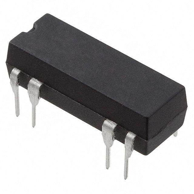
| 描述 | RELAY REED SPST 500MA 5V簧片继电器 DIP 5/6VDC SPST-NC |
| 产品分类 | |
| 品牌 | TE Connectivity |
| 产品手册 | http://www.te.com/catalog/pn/en/JWD-171-17?RQPN=JWD-171-17 |
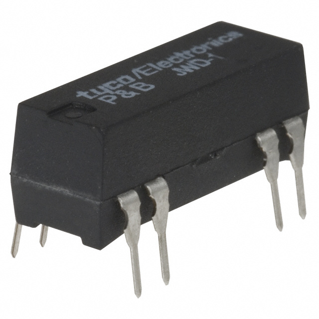
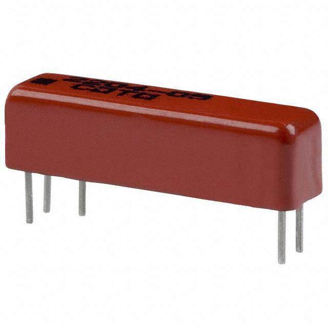
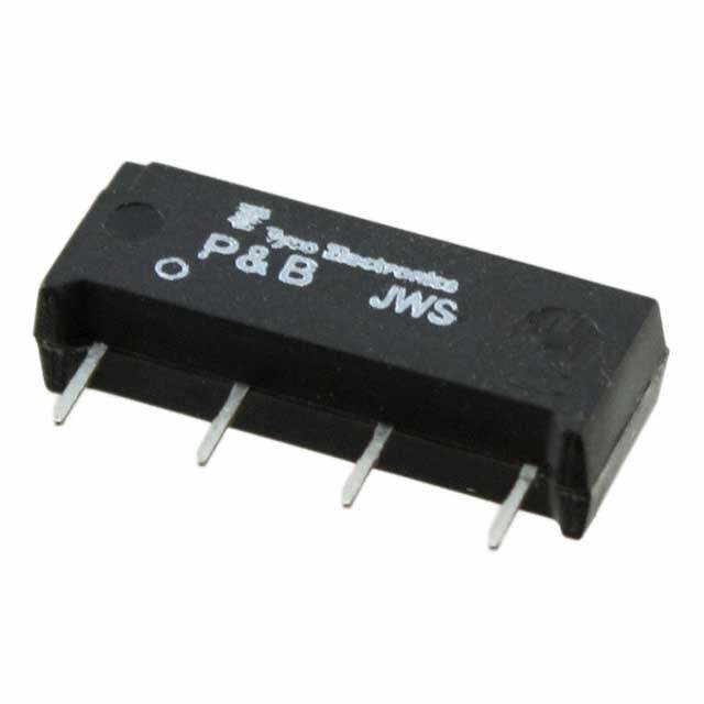
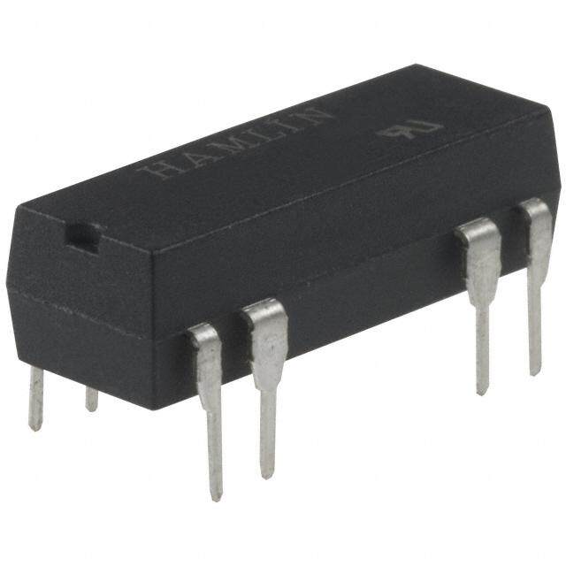
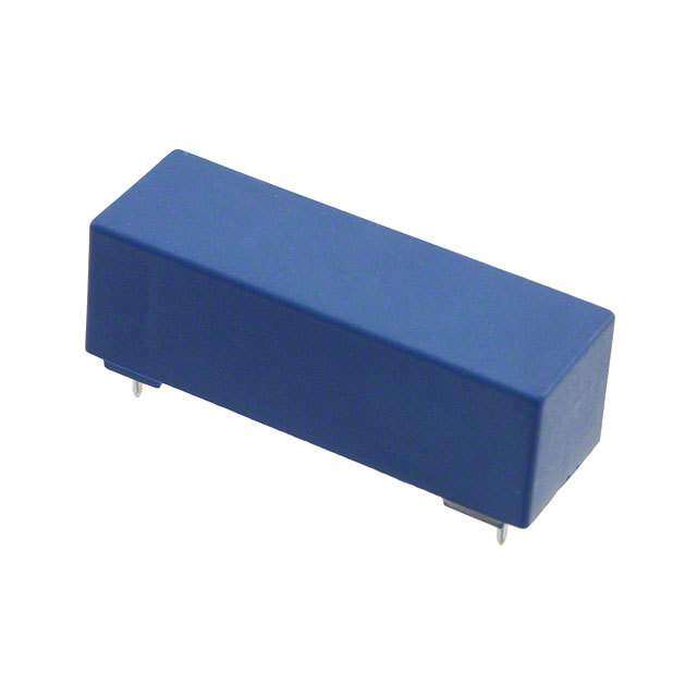
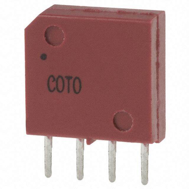
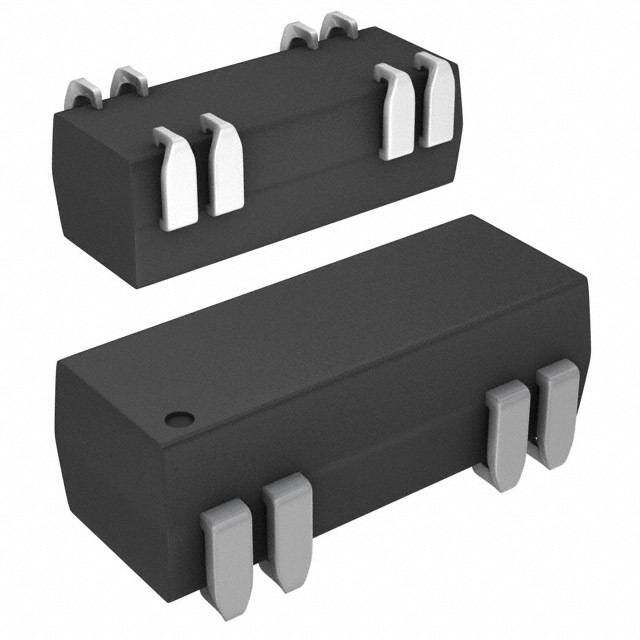
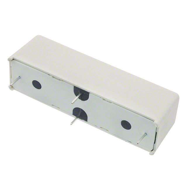
| 产品图片 |
|
| rohs | 符合RoHS无铅 / 符合限制有害物质指令(RoHS)规范要求 |
| 产品系列 | 簧片继电器,TE Connectivity / P&B JWD-171-17JWD,Potter & Brumfield |
| mouser_ship_limit | 该产品可能需要其他文件才能进口到中国。 |
| 数据手册 | http://www.te.com/commerce/DocumentDelivery/DDEController?Action=srchrtrv&DocNm=1308242_JWD-JWS&DocType=DS&DocLang=English |
| 产品型号 | JWD-171-17 |
| 产品目录绘图 |
|
| 产品目录页面 | |
| 产品种类 | 簧片继电器 |
| 关闭电压(最小值) | 0.5 VDC |
| 其它名称 | 1-1393771-1 |
| 包装 | 管件 |
| 商标 | TE Connectivity / P&B |
| 安装类型 | 通孔 |
| 导通电压(最大值) | 3.8 VDC |
| 工作时间 | 1.5ms |
| 工作温度 | -35°C ~ 85°C |
| 工厂包装数量 | 25 |
| 开关电压 | 100VDC - 最小值 |
| 最大开关功率 | 50 mW to 72 mW |
| 最大开关电流 | 0.5 A |
| 标准包装 | 25 |
| 特性 | |
| 特色产品 | http://www.digikey.com/cn/zh/ph/te/relays.html |
| 端子类型 | PC 引脚 |
| 类型 | Dry Reed Relays |
| 线圈功率 | 50 mW |
| 线圈抑制二极管 | Yes |
| 线圈电压 | 5VDC |
| 线圈电流 | 10mA |
| 线圈电阻 | 500 欧姆 |
| 线圈类型 | 无锁存 |
| 继电器类型 | 舌簧 |
| 触头外形 | SPST-NC(1 B 型) |
| 触头材料 | 钌(Ru) |
| 触点形式 | 1 Form B (SPST-NC) |
| 触点材料 | Ruthenium |
| 释放时间 | 0.5ms |
| 零件号别名 | 1-1393771-1 |
| 额定接触(电流) | 500mA |


- 商务部:美国ITC正式对集成电路等产品启动337调查
- 曝三星4nm工艺存在良率问题 高通将骁龙8 Gen1或转产台积电
- 太阳诱电将投资9.5亿元在常州建新厂生产MLCC 预计2023年完工
- 英特尔发布欧洲新工厂建设计划 深化IDM 2.0 战略
- 台积电先进制程称霸业界 有大客户加持明年业绩稳了
- 达到5530亿美元!SIA预计今年全球半导体销售额将创下新高
- 英特尔拟将自动驾驶子公司Mobileye上市 估值或超500亿美元
- 三星加码芯片和SET,合并消费电子和移动部门,撤换高东真等 CEO
- 三星电子宣布重大人事变动 还合并消费电子和移动部门
- 海关总署:前11个月进口集成电路产品价值2.52万亿元 增长14.8%


PDF Datasheet 数据手册内容提取
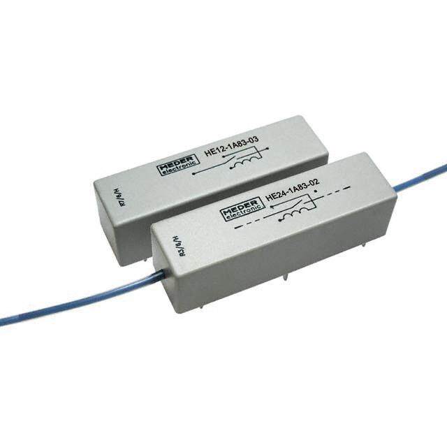
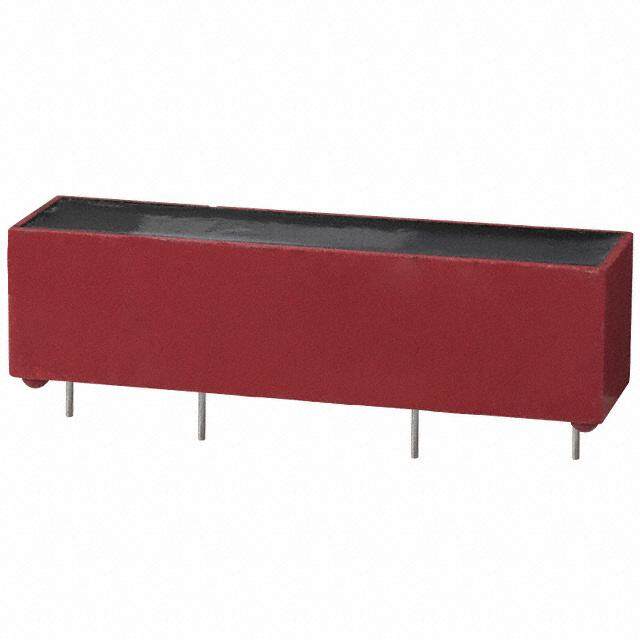
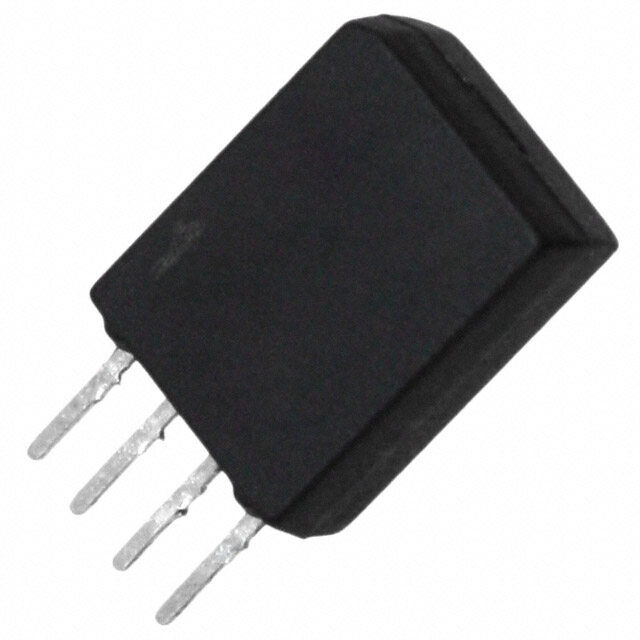
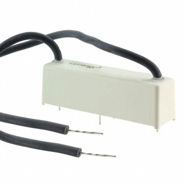
Signal Relays Potter & Brumfield JWD/JWS Series Reed Relays n JWD has dual in-line package (DIP) configuration (14-pin DIP) n JWS has single in-line package (SIP) configuration n Low cost, dry reed reliability with various contact arrangements n Wave solderable and immersion cleanable molded epoxy package n Optional coil suppression diode Typical applications Telecommunications, measurement and control, automated test equipment, security systems, medical equipment. U C Approvals Coil Data UL E29244, CSA LR81479 Coil voltage range 5 to 24VDC Technical data of approved types on request Min./Max. energization duration continuous Max. coil temperature 105º C Contact Data Thermal resistance approximately 100ºC/W Contact arrangement Coil insulation system according UL class A JWD and JWS 1 form A (NO) contact JWD only 1 form B (NC), 1 form C (CO), 2 form A (NO) Insulation Data Rated voltage Initial dielectric strength 1 form A, 1 form B and 2 form A 20VDC, 500mA between open contacts 1 form C (CO) 10 VDC, 500mA and 10VDC, 10mA form A (NO) and form B (NC) 250VDC, Max. switching voltage form C (CO) 175VDC 1 form A, 1 form B and 2 form A 100VDC between contact and coil 500VDC 1 form C (CO) 28VDC between adjacent contacts Rated current 2 form A (NO) of JWD only 500VDC 1 form A, 1 form B and 2 form A 500mA, 20VDC Initial insulation resistance 1 form C (CO) 500mA, 10VDC between insulated elements 1010Ω at 100VDC Limiting making current 500mA Capacitance between open contacts typ. 0.5pF Limiting breaking current 500mA Switching power form A (NO) and form B (NC) 10W Other Data form C (CO) 3W Material compliance: EU RoHS/ELV, China RoHS, REACH, Halogen content Contact material Ruthenium refer to the Product Compliance Support Center at Min. recommended contact load 10mV, 10mA www.te.com/customersupport/rohssupportcenter Minimum switching voltage 10mV Ambient temperature -35ºC to +85ºC Initial contact resistance 200mΩ max. at 10mA, 6VDC Category of environmental protection Frequency of operation 100Hz IEC 61810 RTIII -wash tight Operate/release time max., incl. bounce Vibration resistance (functional) 20g, 10 to 2000 Hz form A (NO) and form B (NC) 1.5/0.5ms Shock resistance (functional), 3 planes, half sine pulse, 8ms form C (CO) 1.5/3.0ms form A (NO) 100g Electrical endurance form B (NC) and form C (CO) 50g form A (NO) and form B (NC), resistive load, +25°C Terminal type PCB-THT 20VDC, 500mA 1x10⁶ ops. Mounting position any 20VDC, 250mA 20x106 ops. Weight approximately 2.3g ( 0.08 oz.) 5VDC, 1mA 100x106 ops. Resistance to soldering heat THT form C (CO) contact, resistive load, +25°C IEC 60068-2-20, wave solder max. 260ºC/10s 10VDC, 500mA 1x10⁶ ops. Ultrasonic cleaning no 10VDC, 250mA 20x106 ops. Conformal coating yes 5VDC, 1mA 100x106 ops. Packaging/unit tray/50 pcs., Contact ratings bundle/250 pcs., 1 form A, 1 form B and 2 form A 500mA, 20VDC box/500 pcs. 1 form C (CO) 500mA, 10VDC Mechanical endurance 100x106 operations 1 07-2012, Rev. 0712 Datasheets and product specification Datasheets and product data is subject to the Datasheets, product data, ‘Definitions’ sec- www.te.com according to IEC 61810-1 and to be used terms of the disclaimer and all chapters of tion, application notes and all specifications © 2011 Tyco Electronics Corporation, only together with the ‘Definitions’ section. the ‘Definitions’ section, available at are subject to change. a TE Connectivity Ltd. company http://relays.te.com/definitions
Signal Relays Potter & Brumfield JWD/JWS Series Reed Relays (Continued) Terminal assignment Dimensions TOP view on component side of PCB Dia. 1 Dia. 2 Dia. 3 Dia. 4 JWD Series 7 6 +21 7 6 +21 7 6 +21 7 6 +21 .770 MAX. .300 MAX. (19.56) (7.62) .130 ± .015 MAGNET (3.3 ± 0.4) 1 2 6 7 .315 (8.0) MAX. 8 9 1314 8 9 1314 8 9 1314 8 9 1314 WITH TERMINALS VERTICAL 7 6 +21 7 21 .020 TYP. (.51) .100 TYP. .600 4° MAX. .012 TYP. (2.54) (15.24) TYP. (.3) 8 9 1314 8 9 1314 1 +3 5 7 Dia. 5 Dia. 6 Dia. 7 JWS Series Note: Terminal numbers are for reference only and do not appear on relays. .800 MAX. .260 MAX. (20.32) (6.6) .307 MAX. (7.8) 1 3 5 7 .020 TYP. .018 TYP. .010 TYP. (.51) (.46) (.25) Note: Magnetic shielding may be required between relays when they are placed in very close proximity to one another. .200 TYP. .125 ± .010 (5.08) (3.18 ± .254) Product code Contacts Max. Diode Coil Coil Operate Coil Wiring Part number rating voltage resistance1) voltage power diagram JWD-107-1 1 form A, 10W No 5/6VDC 500ohm 3.8VDC 50/72mW 1 1393771-3 JWD-107-5 1 NO contact Yes 5/6VDC 500ohm 3.8VDC 50/72mW 1 1393771-5 JWD-107-3 No 12VDC 1200ohm 9.6VDC 120mW 1 1393771-4 JWD-107-7 Yes 12VDC 1200ohm 9.6VDC 120mW 1 1393771-6 JWD-171-5 No 24VDC 2150ohm 19.2VDC 268mW 2 2-1393771-0 JWD-171-10 Yes 24VDC 2150ohm 19.2VDC 268mW 2 1393771-7 JWD-171-21 2 form A, No 5/6VDC 200ohm 3.8VDC 125/180mW 3 1-1393771-4 JWD-171-25 2 NO contacts Yes 5/6VDC 200ohm 3.8VDC 125/180mW 3 1-1393771-7 JWD-171-23 No 12VDC 500ohm 9.6VDC 288mW 3 1-1393771-5 JWD-171-27 Yes 12VDC 500ohm 9.6VDC 288mW 3 1-1393771-8 JWD-171-24 No 24VDC 2200ohm 19.2VDC 262mW 3 1-1393771-6 JWD-171-28 Yes 24VDC 2200ohm 19.2VDC 262mW 3 1-1393771-9 JWD-171-12 1 form B, No 5/6VDC 500ohm 3.8VDC 50/72mW 4 1393771-8 JWD-171-17 1 NCO contact Yes 5/6VDC 500ohm 3.8VDC 50/72mW 4 1-1393771-1 JWD-171-14 No 12VDC 1200ohm 9.6VDC 120mW 4 1393771-9 JWD-171-19 Yes 12VDC 1200ohm 9.6VDC 120mW 4 1-1393771-2 JWD-171-15 No 24VDC 2200ohm 19.2VDC 262mW 4 1-1393771-0 JWD-171-20 Yes 24VDC 2200ohm 19.2VDC 262mW 4 1-1393771-3 JWD-172-1 1 form C, 3W No 5/6VDC 200ohm 3.8VDC 125/180mW 5 2-1393771-1 JWD-172-5 1 CO contact Yes 5/6VDC 200ohm 3.8VDC 125/180mW 5 2-1393771-9 JWD-172-3 No 12VDC 500ohm 9.6VDC 288mW 5 2-1393771-7 JWD-172-7 Yes 12VDC 500ohm 9.6VDC 288mW 5 3-1393771-0 JWD-172-4 No 24VDC 2200ohm 19.2VDC 262mW 5 2-1393771-8 JWD-172-8 Yes 24VDC 2200ohm 19.2VDC 262mW 5 3-1393771-1 JWD-172-155 No 5/6VDC 200ohm 3.8VDC 125/180mW 6 2-1393771-2 JWD-172-159 Yes 5/6VDC 200ohm 3.8VDC 125/180mW 6 2-1393771-4 JWD-172-161 Yes 12VDC 1000ohm 9.6VDC 144mW 6 2-1393771-5 JWD-172-158 No 24VDC 2150ohm 19.2VDC 268mW 6 2-1393771-3 JWD-172-162 Yes 24VDC 2150ohm 19.2VDC 268mW 6 2-1393771-6 JWS-117-1 1 form A, 10W No 5VDC 500ohm 3.8VDC 50mW 7 3-1393771-2 JWS-117-6 1 NO contact Yes 5VDC 500ohm 3.8VDC 50mW 7 3-1393771-8 JWS-117-3 No 12VDC 530ohm 9.6VDC 272mW 7 3-1393771-4 JWS-117-8 Yes 12VDC 530ohm 9.6VDC 272mW 7 3-1393771-6 JWS-117-18 Yes 12VDC 1850ohm 9.6VDC 78mW 7 3-1393771-3 JWS-117-5 No 24VDC 2150ohm 19.2VDC 268mW 7 3-1393771-5 1) Coil resistance ±10%. 2 07-2012, Rev. 0712 Datasheets and product specification Datasheets and product data is subject to the Datasheets, product data, ‘Definitions’ sec- www.te.com according to IEC 61810-1 and to be used terms of the disclaimer and all chapters of tion, application notes and all specifications © 2011 Tyco Electronics Corporation, only together with the ‘Definitions’ section. the ‘Definitions’ section, available at are subject to change. a TE Connectivity Ltd. company http://relays.te.com/definitions