 Datasheet下载
- 型号: 9012-05-11
- 制造商: Coto Technology
- 库位|库存: xxxx|xxxx
- 要求:
| 数量阶梯 | 香港交货 | 国内含税 |
| +xxxx | $xxxx | ¥xxxx |
查看当月历史价格
查看今年历史价格
9012-05-11产品简介:
ICGOO电子元器件商城为您提供9012-05-11由Coto Technology设计生产,在icgoo商城现货销售,并且可以通过原厂、代理商等渠道进行代购。 9012-05-11价格参考。Coto Technology9012-05-11封装/规格:笛簧继电器, 。您可以下载9012-05-11参考资料、Datasheet数据手册功能说明书,资料中有9012-05-11 详细功能的应用电路图电压和使用方法及教程。
Coto Technology品牌的笛簧继电器型号9012-05-11是一种微型、低功耗的继电器,广泛应用于需要高可靠性和小尺寸的场景。以下是其主要应用场景:

 1. 医疗设备
   - 用于便携式医疗设备(如血糖仪、血压计、心率监测器等)中,实现信号切换和控制功能。
   - 在诊断仪器中,用于控制低电压或低电流电路。

 2. 工业自动化
   - 适用于工业控制系统中的信号隔离与转换,例如PLC模块、传感器接口等。
   - 用于小型化设备中的开关控制,确保高效且稳定的运行。

 3. 通信设备
   - 应用于通信终端设备(如路由器、调制解调器等)中的信号切换。
   - 在物联网(IoT)设备中,用于数据传输路径的切换和控制。

 4. 消费电子
   - 用于家用电器(如智能音箱、遥控器、智能家居控制器等)中的电路切换。
   - 在便携式电子产品中,提供低功耗的开关解决方案。

 5. 汽车电子
   - 用于车载电子系统(如导航系统、娱乐系统、传感器控制等)中的信号处理。
   - 在电动车窗、门锁等小型控制模块中实现可靠的开关功能。

 6. 测试与测量
   - 在测试仪器(如示波器、万用表等)中,用于信号通道的选择和切换。
   - 适用于需要精确控制的小型化测试设备。

 7. 安全系统
   - 用于安防设备(如报警系统、监控摄像头等)中的信号传输和控制。
   - 在门禁系统中,实现电路的快速切换和稳定运行。

该型号的笛簧继电器以其紧凑的设计、高灵敏度和长寿命特点,非常适合对空间和能耗有严格要求的应用场合。同时,其高可靠性也使其成为关键任务应用的理想选择。
| 参数 | 数值 |
| 产品目录 | |
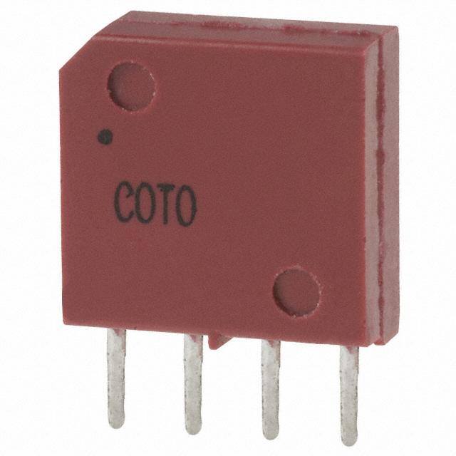
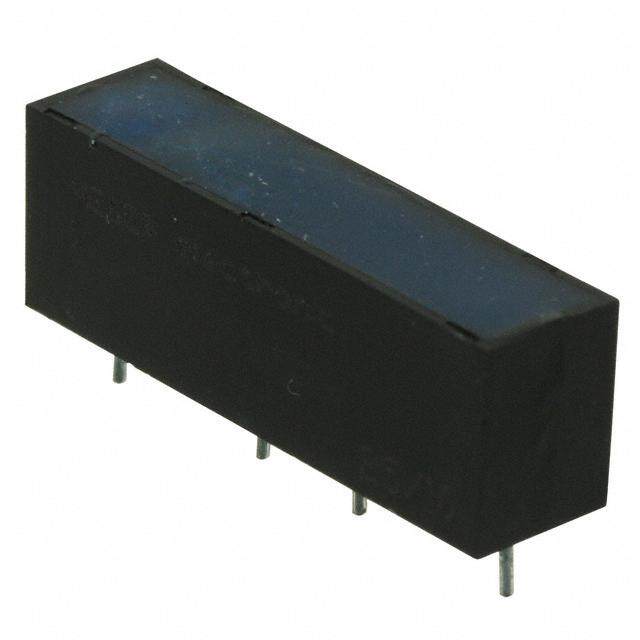
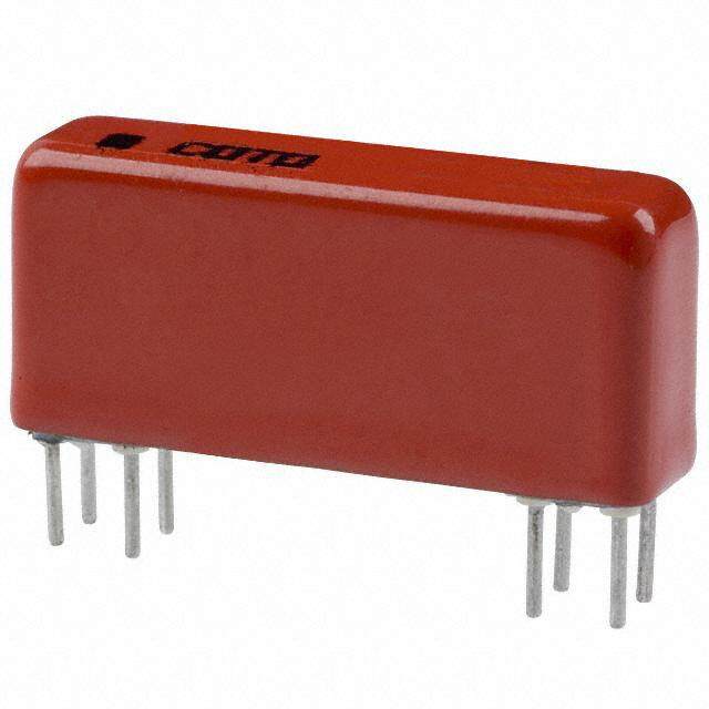
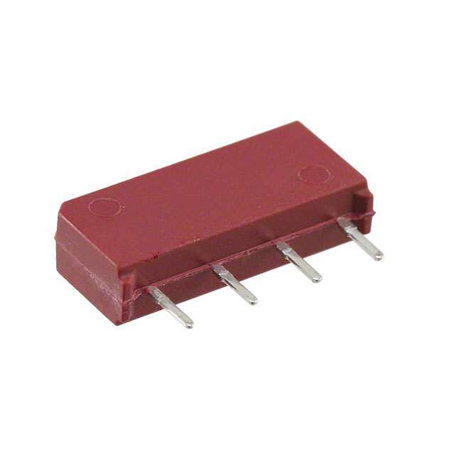
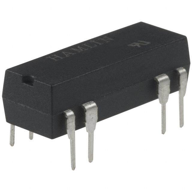
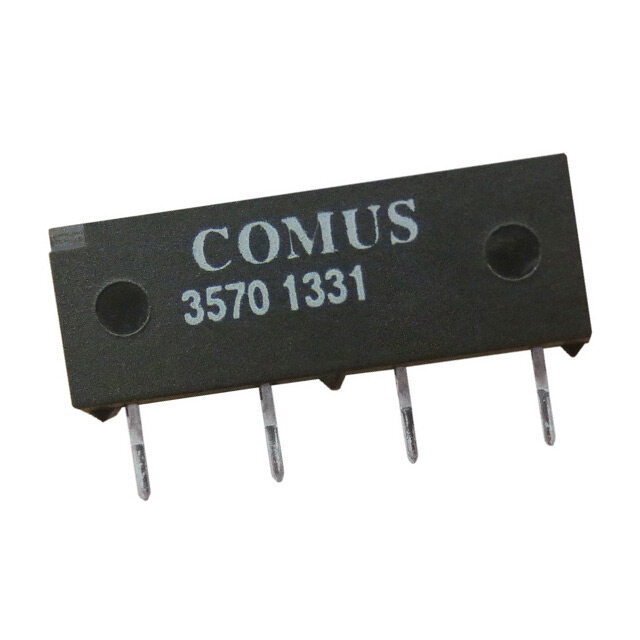
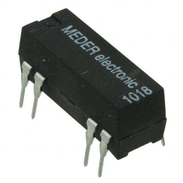
| 描述 | RELAY REED SPST 500MA 5V |
| 产品分类 | |
| 品牌 | Coto Technology |
| 数据手册 | |
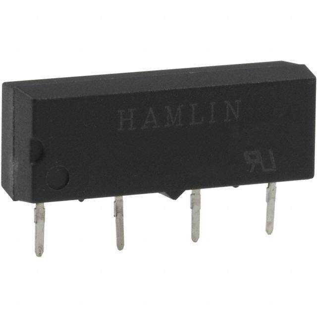
| 产品图片 |
|
| 产品型号 | 9012-05-11 |
| rohs | 无铅 / 符合限制有害物质指令(RoHS)规范要求 |
| 产品系列 | 9012 |
| 产品目录绘图 |
|
| 产品目录页面 | |
| 关闭电压(最小值) | 0.4 VDC |
| 其它名称 | 306-1135 |
| 包装 | 管件 |
| 安装类型 | 通孔 |
| 导通电压(最大值) | 3.75 VDC |
| 工作时间 | 0.35ms |
| 工作温度 | -20°C ~ 85°C |
| 应用说明 | |
| 开关电压 | 200VAC,200VDC - 最小值 |
| 标准包装 | 39 |
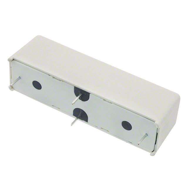
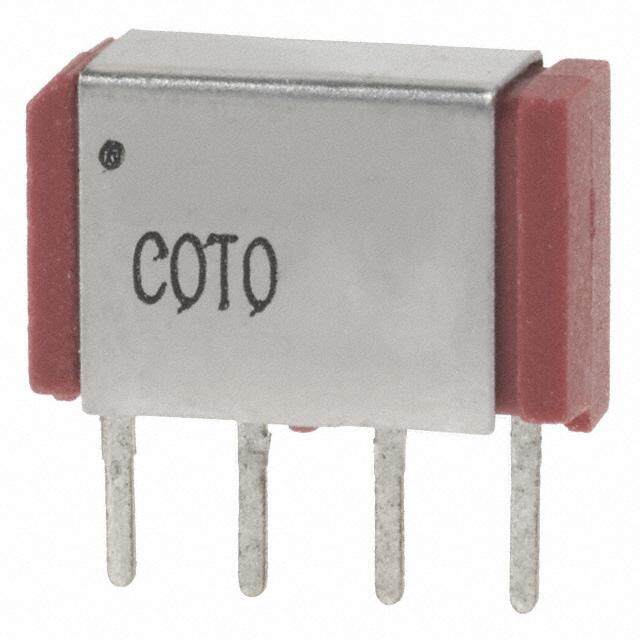
| 特性 | 二极管,带磁屏蔽 |
| 端子类型 | PC 引脚 |
| 线圈功率 | - |
| 线圈电压 | 5VDC |
| 线圈电流 | 10mA |
| 线圈电阻 | 500 欧姆 |
| 线圈类型 | 无锁存 |
| 继电器类型 | 舌簧 |
| 触头外形 | SPST-NO(1 A 型) |
| 触头材料 | - |
| 释放时间 | 0.1ms |
| 额定接触(电流) | 500mA |


- 商务部:美国ITC正式对集成电路等产品启动337调查
- 曝三星4nm工艺存在良率问题 高通将骁龙8 Gen1或转产台积电
- 太阳诱电将投资9.5亿元在常州建新厂生产MLCC 预计2023年完工
- 英特尔发布欧洲新工厂建设计划 深化IDM 2.0 战略
- 台积电先进制程称霸业界 有大客户加持明年业绩稳了
- 达到5530亿美元!SIA预计今年全球半导体销售额将创下新高
- 英特尔拟将自动驾驶子公司Mobileye上市 估值或超500亿美元
- 三星加码芯片和SET,合并消费电子和移动部门,撤换高东真等 CEO
- 三星电子宣布重大人事变动 还合并消费电子和移动部门
- 海关总署:前11个月进口集成电路产品价值2.52万亿元 增长14.8%
PDF Datasheet 数据手册内容提取
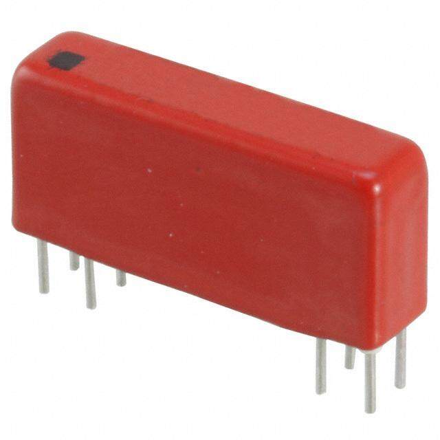
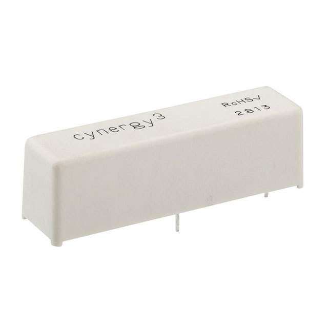
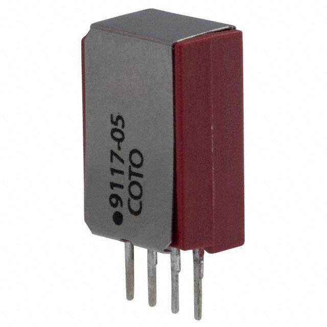
9011, 9012 & 9117 MINIATURE SIP RELAYS 9011, 9012 & 9117 Series Miniature Molded SIP Reed Relays The 9011, 9012 & 9117 are compact versions of Coto’s standard 9000 SIPs, with the 9011 and 9117 using 65% less board space and the 9012 using 47% less board space (LxW). These miniature SIP relays are ideal for use in ATE applications and other high reliability test, measurement and telecommunications applications where high board density and long life are key requirements. 9011, 9012 & 9117 Series Features u 9012 is a 10W SIP relay (.400” x .150” x .400”) u 9011 is a 3W SIP relay (.400” x .150” x .265”) u 9117 is the smallest 3W SIP relay (.270” x .150” x .385”) u Magnetic shielding reduces interaction u Optional coil suppression diode protects coil drive circuits u UL File #E67117 - Contact factory for details u High insulation resistance 1012Ω minimum u High speed switching u Molded thermoset body on integral lead frame design u High reliability, hermetically sealed contacts for long life u RoHS compliant DIMENSIONS in Inches (Millimeters) Model 9011 Model 9012 IDENTIFIES 0.400 Max. 0.150 Max. 0.400 Max. .150 Max. PIN #1 (10.16) (3.81) IDENTIFIES (10.16) (3.81) PIN #1 .265 Max. 0.020 (6.73) .400 Max. (0.51) 1 2 3 4 (10.16) 0.015 1 2 3 4 (.381) 0.050 Ref. 0.010 Typ. (1.27) 0.130 0.100 (3.30) (0.25) (2.54) 30o 0.050 0.130 0.010 Typ. 0.200 (1.27) (3.30) (0.25) (5.08) SEE LEAD DETAIL 0.100 0.300 (2.54) (7.62) 0.200 .012 (5.08) 0.025 .020 (0.30) 0.300 SEE LEAD DETAIL (0.64) (0.51) (7.62) LEAD DETAIL (TYP.) Model 9117 IDENTIFIES PIN #1 .270 Max .150 Max (6.85) (3.81) Ordering Information .385 Max Part Number 90XX-XX-1X (9.77) Model Number General Options2 .011 (.27) 9011 9012 9117 0=No Diode 1 2 3 4 .015 Typ. Coil Voltage 1=Diode (.38) .125 (3.17) 05=5 volts .044 Ref. (1.11) (.0.2150) 12=12 volts (N/A on 9117) .060 (1.52) .120 (3.04) Magnetic Shield .180 (4.57) 1=Mag Shield (External 9011, 9117; Internal 9012) 07082013 tel: (401) 943.2686 | fax: (401) 942.0920
MODEL NUMBER 90112,3 90122,3 91172,3 Parameters Test Conditions Units (3 Watt) (10 Watt) (3 Watt) 4 Pin SIP 4 Pin SIP Narrow Fit COIL SPECS. Nom. Coil Voltage VDC 5 12 5 12 5 Max. Coil Voltage VDC 6.5 15.0 6.5 15.0 6.0 Coil Resistance +/- 10%, 25° C Ω 500 750 500 750 400 Operate Voltage Must Operate by VDC - Max. 3.75 9.0 3.75 9.0 3.75 Release Voltage Must Release by VDC - Min. 0.4 1.0 0.4 1.0 0.5 CONTACT RATINGS Switching Voltage Max DC/Peak AC Resist. Volts 100 200 100 Switching Current Max DC/Peak AC Resist. Amps 0.25 0.5 0.25 Carry Current Max DC/Peak AC Resist. Amps 0.5 0.5 0.5 Contact Rating Max DC/Peak AC Resist. Watts 3 10 3 Life Expectancy-Typical1 Signal Level 1.0V, 10mA x 106 Ops. 250 1000 250 Static Contact 50mV, 10mA Ω 0.150 0.120 0.120 Resistance (max. init.) Dynamic Contact 0.5V, 50mA Ω 0.200 0.200 0.200 Resistance (max. init.) at 100 Hz, 1.5 msec RELAY SPECIFICATIONS Insulation Resistance Between all Isolated Pins Ω 1012 1012 1012 (minimum) at 100V, 25°C, 40% RH Capacitance - Typical pF 0.7 0.7 0.14 Across Open Contacts Open Contact to Coil pF 1.4 1.4 N/A Dielectric Strength Between Contacts VDC/peak AC 200 200 150 (minimum) Contacts to Coil VDC/peak AC 1500 1500 1500 Operate Time - including At Nominal Coil Voltage, msec. 0.35 0.35 0.2 bounce - Typical 30 Hz Square Wave Release Time - Typical msec. 0.1 0.1 0.1 1 Top View: Grid = .1”x.1” (2.54mm x 2.54mm) 2 3 4 Notes: 1 Consult factory for life expectancy at other switching loads. Resistance >0.5Ω defines end of life or failure to open. 2 Optional diode is connected to pin #2(+) and pin #3(-) for 9011 & 9012; pin #1(+) and pin #2(-) for 9117. Correct coil polarity must be observed. 3 9011 & 9117 external mag shield. 9012 internal mag shield. Environmental Ratings: Storage Temp: -35°C to +100°C; Operating Temp: -20°C to +85°C; Solder Temp: 270°C max; 10 sec. max All electrical parameters measured at 25°C unless otherwise specified. Vibration: 20 G’s to 2000 Hz; Shock: 50 G’s 07082013 For most recent data visit www.cotorelay.com COTO TECHNOLOGY, INC.
Mouser Electronics Authorized Distributor Click to View Pricing, Inventory, Delivery & Lifecycle Information: C oto Technology: 9011-05-10 9012-05-10 9117-05-11 9117-05-10 9011-12-10 9011-05-11 9011-12-11 9012-12-10 9012-12-11 9012-05-11