ICGOO在线商城 > 集成电路(IC) > PMIC - LED 驱动器 > ISL97801ARZ

 Datasheet下载
- 型号: ISL97801ARZ
- 制造商: Intersil
- 库位|库存: xxxx|xxxx
- 要求:
| 数量阶梯 | 香港交货 | 国内含税 |
| +xxxx | $xxxx | ¥xxxx |
查看当月历史价格
查看今年历史价格
ISL97801ARZ产品简介:
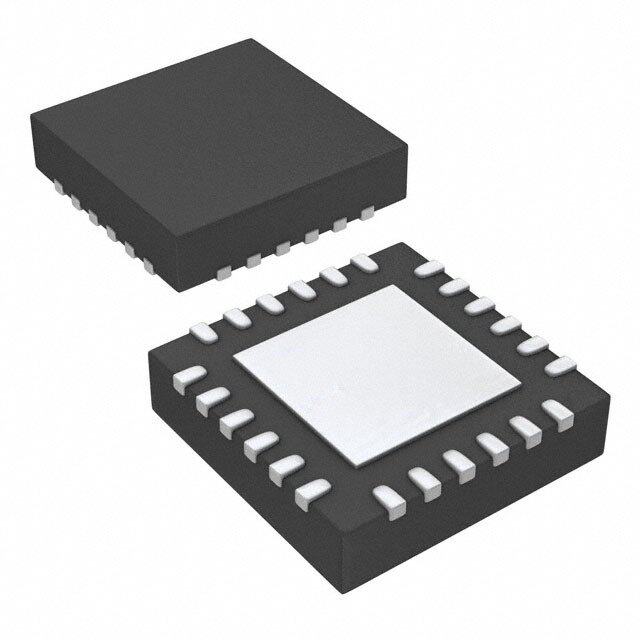
ICGOO电子元器件商城为您提供ISL97801ARZ由Intersil设计生产,在icgoo商城现货销售,并且可以通过原厂、代理商等渠道进行代购。 ISL97801ARZ价格参考。IntersilISL97801ARZ封装/规格:PMIC - LED 驱动器, LED 驱动器 IC 1 输出 DC DC 稳压器 降压,升压 模拟,PWM 调光 1A 20-QFN(4x4)。您可以下载ISL97801ARZ参考资料、Datasheet数据手册功能说明书,资料中有ISL97801ARZ 详细功能的应用电路图电压和使用方法及教程。
ISL97801ARZ 是瑞萨电子(Renesas Electronics America Inc.)生产的一款LED驱动器,属于PMIC(电源管理集成电路)中的LED驱动器类别。

该器件主要应用于需要高效、高亮度LED背光驱动的场合,尤其适用于中小尺寸液晶显示屏(LCD)的背光系统。典型应用场景包括:

1. 便携式电子产品:如智能手机、平板电脑、电子书阅读器等设备的LCD背光驱动;
2. 工业显示设备:用于人机界面(HMI)、工业控制面板、测量仪器等显示模块的背光控制;
3. 车载显示系统:如车载导航仪、仪表盘显示屏、后视摄像头显示等;
4. 消费类电子产品:如数码相框、便携式游戏机、智能穿戴设备等。

ISL97801ARZ采用升压拓扑结构,支持多颗LED串联驱动,具备调光功能,可通过PWM或模拟方式进行亮度调节。同时其具有过温保护、过压保护和短路保护等功能,提高了系统稳定性和可靠性。

总之,ISL97801ARZ广泛适用于对效率、亮度控制及空间布局有较高要求的LED背光应用领域。
| 参数 | 数值 |
| 产品目录 | 集成电路 (IC) |
| 描述 | IC LED DRIVER AUTOMOTIVE 20-QFN |
| 产品分类 | |
| 品牌 | Intersil |
| 数据手册 | |
| 产品图片 |
|
| 产品型号 | ISL97801ARZ |
| PCN设计/规格 | |
| rohs | 无铅 / 符合限制有害物质指令(RoHS)规范要求 |
| 产品系列 | - |
| 供应商器件封装 | 20-QFN(4x4) |
| 内部驱动器 | 是 |
| 包装 | 管件 |
| 安装类型 | 表面贴装 |
| 封装/外壳 | 20-VFQFN 裸露焊盘 |
| 工作温度 | -40°C ~ 105°C |
| 恒压 | - |
| 恒流 | - |
| 拓扑 | PWM,降压(降压),升压(升压) |
| 标准包装 | 75 |
| 电压-电源 | 2.7 V ~ 16 V |
| 电压-输出 | 32V |
| 类型-初级 | 车载,背光 |
| 类型-次级 | - |
| 输出数 | 1 |
| 频率 | 850kHz ~ 1.15MHz |


- 商务部:美国ITC正式对集成电路等产品启动337调查
- 曝三星4nm工艺存在良率问题 高通将骁龙8 Gen1或转产台积电
- 太阳诱电将投资9.5亿元在常州建新厂生产MLCC 预计2023年完工
- 英特尔发布欧洲新工厂建设计划 深化IDM 2.0 战略
- 台积电先进制程称霸业界 有大客户加持明年业绩稳了
- 达到5530亿美元!SIA预计今年全球半导体销售额将创下新高
- 英特尔拟将自动驾驶子公司Mobileye上市 估值或超500亿美元
- 三星加码芯片和SET,合并消费电子和移动部门,撤换高东真等 CEO
- 三星电子宣布重大人事变动 还合并消费电子和移动部门
- 海关总署:前11个月进口集成电路产品价值2.52万亿元 增长14.8%


PDF Datasheet 数据手册内容提取
DATASHEET NOT RECOMMENDED FOR NEW DESIGNS ISL97801 RECOMMENDED REPLACEMENT PART ISL97634 FN6428 High Power LED Driver Rev 1.00 April 2, 2007 The ISL97801 is a high-power LED backlight driver with an Features integrated 36V FET designed to drive up to 8 high-power • Drives 3-8 high-power LEDs in series, up to 32V LEDs in series. The PWM converter runs from an internally generated 1MHz clock. With efficiencies over 90% the • 2.7V to 16V input voltage range regulator provides tight control of LED current and may be • Boost or Buck configurable switch configured in either boost or buck topologies, allowing from 3 to 8 series diodes to be driven from wide input voltages. • 3A integrated FET LED light level may be controlled either by: • Automotive load dump protection 1. LED DC bias current set via the LEVEL pin, or • Light output temperature compensation 2. External low frequency PWM control via the • LED over-temperature protection ENABLE/PWM pin. • LED disconnect In both control modes optional over temperature thermal protection of the LED reduces the LED DC bias current • PWM/analog light level control above an adjustable set temperature, protecting the LED • Small, 20 Ld 4mm x 4mm QFN package from thermal damage. An optional fault monitor drives an • Pb-free plus anneal available (RoHS compliant) external FET between the input supply and inductor, providing short circuit current protection for the LED and Applications inductor as well as load dump protection for automotive applications. For low cost applications the pass transistor • Display backlighting may be omitted and the fault pin bypassed. - Automotive - LCD monitor The ISL97801 is packaged in a 20 Ld 4mm x 4mm QFN - Notebook displays package and is specified for operation over the -40°C to +105°C temperature range. • LED accent lighting Ordering Information • Automotive lighting Pinout PART TAPE & NUMBER PART REEL/ PACKAGE PKG. ISL97801 (Note) MARKING QTY (Pb-free) DWG. # (20 LD 4X4 QFN) ISL97801ARZ 978 01ARZ - 20 Ld 4x4 QFN L20.4x4C TOP VIEW ISL97801ARZ-TK 978 01ARZ 13”/ 20 Ld 4x4 QFN L20.4x4C T L T 1,000 VIN FAU GND NC VBA ISL97801ARZ-T 978 01ARZ 13”/ 20 Ld 4x4 QFN L20.4x4C 0 9 8 7 6 2 1 1 1 1 6,000 VDC 1 15ENL NOTE: Intersil Pb-free plus anneal products employ special Pb-free VHI 2 14MODE material sets; molding compounds/die attach materials and 100% matte tin plate termination finish, which are RoHS compliant and OVP 3 THERMAL 13EN/PWM compatible with both SnPb and Pb-free soldering operations. Intersil PAD Pb-free products are MSL classified at Pb-free peak reflow SWD1 4 12SWS1 temperatures that meet or exceed the Pb-free requirements of IPC/JEDEC J STD-020. SWD2 5 11SWS2 6 7 8 9 10 N L P B X T E M F A S V E M OO LE T T B K/ C U B FN6428 Rev 1.00 Page 1 of 20 April 2, 2007
ISL97801 Absolute Maximum Ratings (TA = +25°C) Thermal Information Maximum pin voltage, all pins except below 6.5V Thermal Resistance JA (°C/W) / JC (°C/W) VIN, SWS1, SWS2, EN/PWM . . . . . . . . . . . . . . . . . . . . . . . . . . .18V QFN-20 Package (Notes 1, 2) . . . . . . . 39 2.5 VBAT, FAULT, FB. . . . . . . . . . . . . . . . . . . . . . . . . . . . . . . . . . . . .24V Maximum Junction Temperature . . . . . . . . . . . . . . . . . . . . . .+135°C |VHI - SWS1, SWS2|. . . . . . . . . . . . . . . . . . . . . . . . . . . . . . . . . 6.5V Storage Temperature . . . . . . . . . . . . . . . . . . . . . . .-65°C to +150°C SWD1, SWD2, OVP. . . . . . . . . . . . . . . . . . . . . . . . . . . . . . . . . . .34V Continuous Output Current . . . . . . . . . . . . . . . . . . . . . . . . . . . . . .1A Operating Conditions Temperature Range. . . . . . . . . . . . . . . . . . . . . . . . .-40°C to +105°C CAUTION: Stresses above those listed in “Absolute Maximum Ratings” may cause permanent damage to the device. This is a stress only rating and operation of the device at these or any other conditions above those indicated in the operational sections of this specification is not implied. IMPORTANT NOTE: All parameters having Min/Max specifications are guaranteed. Typical values are for information purposes only. Unless otherwise noted, all tests are at the specified temperature and are pulsed tests, therefore: TJ = TC = TA Operating continuously at a junction temperature of +135°C will shorten the life of the device while the thermal shutdown may trigger at a higher temperature than +135°C since it is a typical number. NOTE: 1. JA is measured in free air with the component mounted on a high effective thermal conductivity test board with “direct attach” features. See Tech Brief TB379. 2. For JC, the “case temp” location is the center of the exposed metal pad on the package underside. Electrical Specifications VBAT = VIN = 12V, VDC = 5V, TA = -40°C to +105°C unless otherwise specified. PARAMETER DESCRIPTION CONDITIONS MIN TYP MAX UNIT VIN Input Supply Voltage IOUT = 350mA, 8 LEDs, BUCK/BOOSTN = 5 16 V GND VIN Input Supply Voltage IOUT = 350mA, 5 LEDs, BUCK/BOOSTN = 2.7 12 V GND, TMAX disabled VBAT Input Supply Monitor Normal operating range 2.7 16 V VBATFAULT Supply Fault Threshold If VBAT > VBATFAULT, FAULT pin is 17.6 21 24 V switched to ground ISEN Supply Current in VIN No switching, EN/PWM = 1 2.7 3.5 mA ISDIS Supply Current in VIN No switching, EN/PWM = 0 0.6 2.5 µA RSWITCH Power FET On Resistance ISWITCH = 600mA 0.15 0.25 VDC Regulated Auxiliary Supply 4.75 5 5.25 V ROUTOL Auxiliary Supply Open Loop Output VIN < VDC 40 Resistance ROUTCL Auxiliary Supply Closed Loop Output VIN > 6V, F < 100Hz 6.5 Resistance IOUT Output Drive Current 4 LED output string. VIN = VBAT = 10V 1 A ILIMBOOST Power Switch Current Limit BUCK/BOOSTN = GND 3.6 A ILIMBUCK Power Switch Current Limit BUCK/BOOSTN = VDC 2.4 A OVPH Over Voltage Positive Going Voltage Upper threshold to enter overvoltage fault 31 32 V Mode Threshold mode, TA = +25°C OVPL Over Voltage Negative Going Voltage Lower threshold to exit overvoltage fault 20 23 V Mode Threshold mode, TA = +25°C VGATE Protection FET VGS (gate clamp) VIN - VFAULT 9.76 12.2 14.64 V VGATE Protection FET VGS (gate clamp) VFAULT - VIN 8.16 10.2 12.24 V VFB Feedback Voltage System in regulation, VLEVEL = 1V, 0.19 0.2 0.21 V VIN = 12V, 6 LEDs FN6428 Rev 1.00 Page 2 of 20 April 2, 2007
ISL97801 Electrical Specifications VBAT = VIN = 12V, VDC = 5V, TA = -40°C to +105°C unless otherwise specified. (Continued) PARAMETER DESCRIPTION CONDITIONS MIN TYP MAX UNIT VLEVEL Light Control Voltage Linear Input Range Mode = 1, analog control of LED current 0.25 3 V FBUV FAULT Feedback Undervoltage Fault VLEVEL = 1V, EN/PWM = 3V 120 160 180 mV FBOV FAULT Feedback Overvoltage Fault VLEVEL = 1V, EN/PWM = 3V 220 250 280 mV fSW Switching Frequency 850 1000 1150 kHz fDIMMING Maximum Recommended PWM Mode = 1, modulation signal applied to 10 kHz Dimming Frequency EN/PWM tSWITCH Load Switch Transition Time CGATE = 2nF 100 ns RLSDRIVERL Load Switch Driver Impedance Low EN/PWM = 0 30 50 RLSDRIVERH Load Switch Driver Impedance High EN/PWM = 3V 30 50 tFAULT Fault Timer Period 40 50 58 ms tDELAY Start-up Delay Timed LX switching delay 0.85 1 1.17 ms VFAULTPUMP Fault Pin Charge Pump VBAT = VIN = 3V 6 V VBOOST Boost Mode Threshold BUCK/BOOSTN = GND 0.4VDC V VBUCK Buck Mode Threshold BUCK/BOOSTN = VDC 0.94VDC V VMODEL Mode Low Threshold MODE = GND 1/3VDC V VMODEH Mode High Threshold MODE = VDC 2/3VDC V enFAULT Input Level Applied to TMAX Pin to 0.9VDC V Enable Fault Protection disFAULT Input Level Applied to TMAX Pin to 0.96VDC V Disable Fault Protection enTEMP Input Level Applied to TEMP Pin to 0.5 V Enable Temperature Compensation disTEMP Input Level Applied to TEMP Pin to 0.08 V Disable Temperature Compensation TCOMPP VFB Positive Temperature VTEMP/VDC = 0.80 1.26 Compensation; VFB/VFBnom TCOMPN VFB Negative Temperature VTEMP/VDC = 0.20 0.74 Compensation; VFB/VFBnom TTRIP Internal Temperature Protection 135 °C Threshold THYS Internal Temperature Protection 25 °C Hysteresis VEN/PWML EN/PWM Pin Input Low Threshold 1.2 V VEN/PWMH EN/PWM Pin Input High Threshold 2.5 V VDCUVLO VDC Under Voltage Lockout 2.6 V Rschottky Internal Schottky Diode for Buck 15 23 . TABLE 1. LIGHT OUTPUT CONTROL, VDC = 5.0V MODE TEMP OPERATING MODE 1 (VDC - 0.25) > V > 0.25V Standard Mode light level to PWM modulation of EN/PWM input; LED bias current determined by LEVEL voltage, nominal 1V Don’t Care V < 0.25V Disable temperature compensation 0 V < (VDC - 0.25) Fixed Bias Mode VFB level internally set to 0.4V, independent of VLEVEL FN6428 Rev 1.00 Page 3 of 20 April 2, 2007
ISL97801 Typical Performance Curves 100 100 8 LEDs 5 LEDs 95 ILEDpeak = 380mA 99%@10kHz 95 ILEDpeak = 380mA 99%@100Hz 99% @ 10kHz 90 90 %) 50%@1kHz %) Y ( 85 Y ( 85 C 10%@10kHz C EN 80 50%@100Hz EN 80 10% @ 10kHz FICI 75 99%@1kHz 10%@1kHz FICI 75 F F 99% @ 100Hz E E 70 50%@10kHz 70 10%@100Hz 65 65 10% @ 100Hz 60 60 6 8 10 12 14 16 18 4 6 8 10 12 14 16 VIN (V) VIN (V) FIGURE 1. 8 LEDs EFFICIENCY vs INPUT VOLTAGE vs FIGURE 2. 5 LEDs EFFICIENCY vs INPUT VOLTAGE vs DIMMING FREQUENCY AND DUTY CYCLE DIMMING FREQUENCY AND DUTY CYCLE 100 100 3 LEDs 95 ILEDpeak = 380mA 95 %) 90 99%@100Hz 99%@10kHz %) 90 8 LEDs EFFICIENCY ( 77880505 10%@10kHz EFFICIENCY ( 77880505 5 LEDs IPLWEDMp e=a 1k0 =k H3z80mA 65 10%@100Hz 65 85 LLEEDDss,, VVIINN == 192VV 60 60 4 6 8 10 0 20 40 60 80 100 VIN (V) PWM DIMMING DUTY CYCLE (%) FIGURE 3. 3 LEDs EFFICIENCY vs INPUT VOLTAGE vs FIGURE 4. 8 AND 5 LEDs EFFICIENCY vs PWM DUTY CYCLE DIMMING FREQUENCY AND DUTY CYCLE 400 4 350 8IL LEDEpDesa,k V =IN 3 =80 1m2VA 5 LEDs @ 100Hz 3 I8L ELDEpDesak = 380mA 300 5 LEDs, VIN = 9V 3 LEDs @ 100Hz 2 3 LEDs, VIN = 5V 1 250 10% @ 100Hz A) %) 0 (mD 200 8 LEDs @ 1kHz (ED -1 ILE 150 8 LEDs @ 10kHz IL -2 10% @ 10kHz -3 100 -4 50 99% @ 10kHz -5 5 LEDs @ 10kHz 99% @ 100Hz 0 -6 0 20 40 60 80 100 6 8 10 12 14 16 18 PWM DIMMING DUTY CYCLE (%) VIN (V) FIGURE 5. LEDs PWM DIMMING LINEARITY FIGURE 6. 8 LEDs CURRENT ACCURACY vs INPUT VOLTAGE FN6428 Rev 1.00 Page 4 of 20 April 2, 2007
ISL97801 Typical Performance Curves (Continued) 10 16 5 LEDs 3 LEDs 8 ILEDpeak = 380mA 14 ILEDpeak = 380mA 6 12 4 10 %) 2 10% @ 100Hz %) 8 (D 0 (D 6 E E IL -2 10% @ 10kHz IL 4 99% @ 10kHz -4 2 99% @ 10kHz -6 0 99% @ 100Hz -8 99% @ 100Hz -2 -10 -4 4 6 8 10 12 14 16 4 5 6 7 8 9 10 VIN (V) VIN (V) FIGURE 7. 5 LEDs CURRENT ACCURACY vs INPUT VOLTAGE FIGURE 8. 3 LEDs CURRENT ACCURACY vs INPUT VOLTAGE 400 420 8 LEDs 415 5 LEDs 395 ILEDpeak = 380mA 410 ILEDpeak = 380mA 390 DUTY CYCLE = 99% 405 DUTY CYCLE = 99% 385 400 mA) 380 A) 339905 I(LED 337705 PWM @ 1kHz I (mLED 333788505 99% @ 10kHz 365 370 PWM @ 10kHz 360 365 355 PWM @ 100Hz 360 99% @ 100Hz 355 350 350 6 8 10 12 14 16 18 4 6 8 10 12 14 16 VIN (V) VIN (V) FIGURE 9. 8 LEDs LINE REGULATION OF PWM DUTY FIGURE 10. 5 LEDs LINE REGULATION OF PWM DUTY CYCLE OF 99% CYCLE OF 99% 410 40 405 I3L ELDEpDesak = 380mA 39 I8L ELDEpDesak = 380mA PWM @ 100Hz 400 DUTY CYCLE = 99% 38 DUTY CYCLE = 10% 395 37 A) 390 A) 36 m PWM @ 100Hz m (D385 (D 35 PWM @ 1kHz LE380 LE 34 PWM @ 10kHz I I 375 33 370 32 PWM @ 10kHz 365 31 360 30 4 5 6 7 8 9 10 6 8 10 12 14 16 18 VIN (V) VIN (V) FIGURE 11. 3 LEDs LINE REGULATION OF PWM DUTY FIGURE 12. 8 LEDs LINE REGULATION OF PWM DUTY CYCLE OF 99% CYCLE OF 10% FN6428 Rev 1.00 Page 5 of 20 April 2, 2007
ISL97801 Typical Performance Curves (Continued) 41 42 5 LEDs 3 LEDs 41 40 ILEDpeak = 380mA ILEDpeak = 380mA PWM @ 100Hz DUTY CYCLE = 10% 40 DUTY CYCLE = 10% 39 10% @ 100Hz 39 A) 38 A) 38 m m (LED 37 (LED 3367 I I 36 10% @ 10kHz 35 34 PWM @ 10kHz 35 33 34 32 6 8 10 12 14 16 18 4 5 6 7 8 9 10 VIN (V) VIN (V) FIGURE 13. 5 LEDs LINE REGULATION OF PWM DUTY FIGURE 14. 3 LEDs LINE REGULATION OF PWM DUTY CYCLE OF 10% CYCLE OF 10% 400 0.1 RSET = 0.5 EN/PWM = 0 350 DUTY CYCLE = 100% VLEVEL = 1V 300 TA = +25°C 250 5 LED 0.01 mA) 8 LED A) (ED200 (mQ IL150 I 0.001 100 50 3 LED 0 0.0001 0 0.2 0.4 0.6 0.8 1.0 6 8 10 12 14 16 18 VLEVEL (V) VIN (V) FIGURE 15. LED CURRENT vs VLEVEL BIAS FIGURE 16. QUIESCENT CURRENT (NON-SWITCHING) 8 LEDs 8 LEDs ILED = 350mA ILED = 350mA FIGURE 17. START-UP WAVEFORMS FIGURE 18. START-UP WAVEFORMS ZOOM-IN FN6428 Rev 1.00 Page 6 of 20 April 2, 2007
ISL97801 Typical Performance Curves (Continued) 8 LEDs VIN = 16V 8 LEDs PWM = 100Hz VIN = 16V PWM = 10kHz FIGURE 19. 50% PWM DIMMING AT 100Hz FIGURE 20. 50% PWM DIMMING AT 10kHz 8 LEDs VIN = 12V PWM = 1kHz 8 LEDs VIN = 16V DUTY CYCLE = 50% PWM = 1kHz FIGURE 21. 10% PWM DIMMING AT 1kHz FIGURE 22. 50% PWM DIMMING AT 1kHz ZOOM-IN TRANSIENT RESPONSE WHEN LOAD DYNAMICALLY TRANSIENT RESPONSE WHEN LOAD DYNAMICALLY CHANGES FROM 7LEDs TO 8LEDs CHANGES FROM 8 LEDs TO 7 LEDs 8 LEDs VO ILEDV =IN 3 5=0 1m2AV VILIEND = = 1 325V0mA 8 LEDs VO 7 LEDs VO 7 LEDs VO FIGURE 23. TRANSIENT RESPONSE OPERATES FROM FIGURE 24. TRANSIENT RESPONSE OPERATES FROM 8 TO 7 LEDs 7 TO 8 LEDs FN6428 Rev 1.00 Page 7 of 20 April 2, 2007
ISL97801 Typical Performance Curves (Continued) FB = 0V 8LEDs VIN = 3.3V ILED = 380mA FIGURE 25. OVP AND RESET FIGURE 26. CURRENT LIMIT Typical Boost Mode Application Diagram VBAT VIN VHI FAULT SWD1 VBAT SWD2 VDC VDC OVP 0.1µF TEMP BUCK/BOOSTN SENSOR TEMP SWS1 TMAX SWS2 PWM EN/PWM ENL MODE FB LEVEL GND 1V FIGURE 27. TYPICAL BOOST MODE APPLICATION CIRCUIT FN6428 Rev 1.00 Page 8 of 20 April 2, 2007
ISL97801 Pin Descriptions PIN NAME DESCRIPTION 1 VDC Internally regulated 5V supply, tracks VIN for input voltages less than 5V. LDO output can also be biased with external supply if VIN is <5.5V. A minimum of 3.3µF decoupling capacitor is needed in this pin. 2 VHI Power FET gate drive supply. Can be biased with external supply if Vin is <5.5V 3 OVP Overvoltage monitor input; tie to VOUT for normal operation 4 SWD1 NMOS power FET drain 5 SWD2 NMOS power FET drain 6 BUCK/BOOSTN Tie to GND for BOOST operation and to VDC for Buck operation 7 LEVEL Sets LED bias current level; VFB(nominal) = VLEVEL/5 8 TEMP Temperature reference, tie to GND to disable temperature compensation 9 FB LED current feedback 10 TMAX Maximum LED temperature set point; if TEMP voltage exceeds TMAX, FB set point will be reduced 11 SWS2 NMOS power FET source 12 SWS1 NMOS power FET source 13 EN/PWM Chip enable and light modulation PWM dimming input 14 MODE Digital Input; tie to GND to set FB reference to 400mV, tie to VDC to control FB reference with LEVEL input 15 ENL LED load isolation MOS gate driver 16 VBAT Input supply monitor 17 NC Leave floating (internally connected) 18 GND Ground return and FB ground reference 19 FAULT Gate drive of fault protection FET. Driven low under fault conditions 20 VIN Input supply FN6428 Rev 1.00 Page 9 of 20 April 2, 2007
ApFN Functional Block Diagram IS ril 2, 26428 L9780 007Rev 2.7V-16V 1 1 .0 0 L VBAT FAULT VIN VDC VHI GND CLOCK AND RAMP GENERATOR START-UP FAULT CONTROL CHARGE PUMP VSTART AND TIMER HALT LDO AND REF REF VSTART CLK RAMP OVP SWD2 VDC SWD1 REF POR CLK INNER LOOP SWS1 RAMP PWM CONTROL LEVEL (T) HALT AND CURRENT LIMIT FET EN O/P CURRENT SENSE SWS2 LIGHT CONTROL LEVEL VDC EN O/P ENL MODE EN/PWM MODE CONTROL TEMPERATURE LOAD FB CURRENT COMPENSATION BUCK/ SENSE BOOSTN ISL97801 HALT TEMP TMAX P a g e 10 FIGURE 28. ISL97801 BLOCK DIAGRAM o f 2 0
ISL97801 Theory of Operation General Description VIN The ISL97801 is a flexible, highly integrated high-power LED FB driver consisting of a PWM switching controller and integrated 3h6igVh -NpDowMeOr SL EpDow's eart FcEurTr.e Tnhtse udpe vtoic 1eA c aant 1d6riVv ein uppu tt oo r8 5 s eLrEieDss VFeoeltdabgaeck LSEHVIFETL GND RSESEN .05 at current up to 350mA at 2.7V input. The control loop can be + configured as either as a boost or buck regulator with the - configuration of the buck/boostn pin, providing an output EL7801 VDC /2 voltage above or below the input supply voltage, depending on the number of stacked LED's. The controller operates from FIGURE 29. FB REFERENCE AUTO SWITCH 2.7V to 16V depending on the numbers of LEDs and current required and can be powered by a single lithium ion battery, 5V Start-up or 12V regulated supplies or automotive electrical systems. To maximize external PWM switching speed, the ISL97801 LED current is sensed through a low value resistor in series does not include an internal soft-start circuit. When VDC with the LED. A thermistor can be used to implement a thermal exceeds the power on reset threshold, switching is delayed for protection scheme to limit the maximum LED temperature to a 1ms (TDELAY) allowing the output capacitor to charge through preset desirable level. the inductor. If soft-start control is required, a suitable Switching Regulator application circuit is shown in Figure 30. The ISL97801 employs a current mode PWM control scheme with a nominal switching frequency of 1MHz. This provides fast VBAT transient response and enables the use of low profile inductors 10µH VBATFAULT L1 and compact multilayer ceramic capacitors. Settling time is VOUT optimized by the use of a simple control loop without an error ISL97801 VIN COUT amplifier, relying instead on intrinsic gain within the direct SWD1 C1 SWD2 4.7nF 20µF summing path. Due to the lower loop gain, offset must be accounted for when setting up initial LED bias current. Refer to R1 the applications section of the datasheet for further FB SWS1SWS2 R2 100 0.5 information. Figure 28 shows a block diagram of the system. 2k RSENSE Application Configurations Operating Modes FIGURE 30. EXTERNAL SOFT-START CIRCUIT The ISL97801 can operate as either a buck or boost regulator. Hardwire BUCK/BOOSTN to GND for boost mode or to VDC Light Level Control for buck mode. In buck mode the power NDMOS drive circuit is Two light control schemes are provided: "floated" (boot-strapped) allowing the NDMOS gate to be driven above VIN to fully enhance the power NDMOS. An 1. An external PWM signal via the EN/PWM pin, providing low internal Schottky diode between VDC (5V) and VHI reduces frequency PWM dimming. external component count. Use a ceramic capacitor of at least 2. Bias current level adjustment via the LEVEL input or fixed 50nF between VHI and SWS1/2 to bootstrap VHI. internal bias. LED Load Connection PWM Dimming ISL97801 includes an auto-sensing FB level shift circuit that LED color temperature varies with bias current. In backlighting enables the LED load to be connected to either GND or VIN. applications PWM dimming offers better control of color An internal sense circuit monitors the FB pin voltage. When the temperature because current through the LED's is kept level exceeds VDC/2, the feedback reference voltage is constant. A 5V gate driver (ENL) synchronized to EN/PWM can switched from GND to VIN. Refer to the application section of be used to control an external N-Ch FET and disconnect the the datasheet for typical application schematics. LED stack during the PWM off period. The switch prevents discharge of the output capacitor by the LED load, maintaining a constant bias independent of PWM duty cycle. Operation at 1kHz PWM rate is shown in Figure 31 and Figure 32. The load disconnect switch improves PWM dynamic range, linearity and color temperature control. To further improve the linearity of FN6428 Rev 1.00 Page 11 of 20 April 2, 2007
ISL97801 PWM dimming, an internal timer delays system shutdown via The value of VFB should be limited to between 50mV and EN/PWM for 50ms. 450mV for linear operation. For minimum light output, VFB may be set below 50mV. With MODE tied to GND, voltage across the feedback resistor is set at ~400mV via an internal reference. In either operating mode, if LED temperature control is enabled the value of VFB will be reduced when maximum LED temperature is exceeded. Input Overvoltage For automotive applications, an external high voltage NFET driven by the FAULT pin disconnects the device from the input supply in response to voltage spikes on the input supply. During start-up an internal charge pump drives the FAULT pin above the input voltage, ensuring the NFET is fully enhanced and powering up the device. In normal operation the switching node of the boost regulator or the floating supply of the buck regulator is used to pump FAULT above VIN. On detection of an overvoltage, the FAULT pin is discharged to GND. The gate to source voltage of the NDMOS is internally limited to ±15V to FIGURE 31. OPERATION WITH ENL CONTROLLED FET prevent voltage stress. Fault Protection The external NFET is also used as a fault protection switch, disconnecting the input supply if a fault occurs for more than 50ms. The system monitors feedback voltage regulation, output overvoltage and input overvoltage. For applications not requiring input voltage or fault protection, connect VBAT and VIN directly together. All faults except input supply overvoltage latch the ISL97801 into an off state that can be cleared by either power cycling the input supply or the EN/PWM pin. Connecting the TMAX pin to VDC disables the fault latch function (LED over temperature control is also disabled). Output Overvoltage Protection (OVP) If the FB pin is shorted to ground or an LED fails open circuit, output voltage in BOOST mode can increase to potentially damaging voltages. An optional overvoltage protection circuit can be enabled by connection of the OVP pin to the output FIGURE 32. OPERATION WITH NO ENL CONTROLLED FET voltage. The device will stop switching if the output voltage Bias Current Dimming exceeds OVPH and re-start when the output voltage falls Current in the LED load is determined by the value of the below OVPL. During sustained OVP fault conditions, VOUT will feedback resistor and the target feedback regulation voltage: saw-tooth between the upper and lower threshold voltages at a frequency determined by the magnitude of current available to V I = -----------F----B-------- (EQ. 1) discharge the output capacitor and the value of output LED RSENSE capacitor used. The OVP threshold can be set to a lower value by using an With MODE tied to VDC, voltage across the feedback resistor external zener diode and resistor, as shown in Figure 33. R1 is set by VLEVEL: should be adjusted to minimize offset in the FB voltage due to FB pin input current. A value of 100 is recommended. V V = -----L---E----V----E----L-- (EQ. 2) FB 5 FN6428 Rev 1.00 Page 12 of 20 April 2, 2007
ISL97801 Component Selection VBAT 10µH Input Capacitor VBATFAULT L1 Switching regulators require input capacitors to deliver peak VOUT VIN charging current and to reduce the impedance of the input ISL97801 COUT SWD1 supply. This reduces interaction between the regulator and SWD2 20µF input supply, improving system stability. The high switching ZOVP R1 frequency of the loop causes almost all ripple current to flow in FB the input capacitor, which must be rated accordingly. SWS1SWS2 100 0.5 RSENSE Considerably more input current ripple is generated in buck mode than boost mode. In buck mode input current is alternately switched between IOUT and zero. The rms current flow in the input capacitor is given by: FIGURE 33. EXTERNAL OVP CIRCUIT 2 (EQ. 3) Over Temperature Shutdown I = I D–D CAPRMS OUT An internal sense circuit disables PWM switching if the die temperature exceeds +135°C. Switching is re-enabled when Where: D = Duty Cycle the temperature falls below +100°C. The input current is maximum for D = 0.5 and when IOUT Internal 5V LDO approaches current limit (2.4A) giving a value of around 1.2A. An internal LDO between VIN and VDC regulates VDC to 5V, A capacitor with low internal series resistance should be to power control and gate drive circuits when VIN exceeds chosen to minimize heating effects and improve system 5.1V. In normal operation decouple VDC with at least 3.3µF. In efficiency, such as X5R or X7R ceramic capacitors, which offer applications where the input supply is less than 5.5V, VDC small size and a lower value of temperature and voltage should be tied directly to VIN. coefficient compared to other ceramic caps. LED Temperature Control In boost mode input current flows continuously into the LED lifetime reduces dramatically with elevated temperature. inductor, with an AC ripple component proportional to the rate An over temperature control circuit utilizing the thermistor of inductor charging only and smaller value input capacitors voltage at TEMP reduces the LED bias current when VTEMP may be used. It is recommended that an input capacitor of at exceeds the threshold voltage on TMAX. To minimize noise least 10µF be used. Ensure the voltage rating of the input injection use a potential divider between VDC and GND to set capacitor is suitable to handle the full supply range. the voltage on TMAX, as shown in Figure 34. The value of In automotive applications the input capacitor can be protected TMAX for a specific threshold temperature is determined by from exposure to high voltages present during fault conditions the choice of thermistor temperature coefficient. Disable the (load dump) by connecting it downstream of the fault protection function by connecting the TMAX pin to VDC and TEMP pin to switch, as shown in Figures 39 and 40. GND. Inductor Careful selection of inductor value will optimise circuit Thermistor 0.47uF CREG Close to operation. Inductor type and value influence many key LED's parameters, including ripple current, current limit, efficiency, VIN VDC RM1 transient performance and stability. Internal slope 20k LDO TMAX RM2 RSESEN .05 c4o.7mµpHe annsadt i1o0nµ hHa.s E bneseunre o tphteim inisdeudc ftoorr icnudrurecntot rr avatinluge sis b ceatpwaebelen 80k of handling the current limit value in the configuration used + (2.4A for buck, 3.5A for boost). If an inductor core is chosen - TEMP with too low a current rating, saturation in the core will cause FB Level Adjust the effective inductor value to fall, leading to an increase in Current Temp RT 10K Compensation GND peak to average current level, poor efficiency and overheating EL7801 in the core. FIGURE 34. OVER-TEMPERATURE CIRCUIT FN6428 Rev 1.00 Page 13 of 20 April 2, 2007
ISL97801 Rectifier Diode In buck mode: A high speed rectifier diode is necessary to prevent excessive V = ---V----I--N-----–-----V----O-----U----T------------D---------------D---------------+ESR (EQ. 7) voltage overshoot, especially in the boost configuration. Low RIPPLE 2f L f C s s OUT forward voltage and reverse leakage current will minimize losses, making Schottky diodes the preferred choice. Similarly where: to the inductor, a diode with a suitable current rating to handle V D = -----O----U----T--- (EQ. 8) current limit in the configuration must be used. V IN Output Capacitor For a low ESR ceramic capacitor, output ripple is dominated by The output capacitor acts to smooth the output voltage and in the charging and discharging of the output capacitor. Care the boost configuaration supplies load current directly during should be taken to ensure the voltage rating of the capacitor the conduction phase of the power switch. Ripple voltage exceeds the maximum output voltage. consists of two components, the first due to charging and Compensation discharging of the capacitor; the second due to IR drop across the ESR of the capacitor by inductor ripple current. The ISL97801 employs a direct summing control loop with current feedback. No error amplifier is used in the system. The In boost mode: arrangement provides fast transient response and makes use V = ------I--O----------D-----+I ESR (EQ. 4) of the output capacitor to compensate the loop. The effect of RIPPLE C F LPK OUT S the pole associated with the inductor is minimized by the current feedback. The number of LEDs, their DC bias current where: and the value of feedback resistor alter loop stability due to V –V D = -----O----U----T--------------I--N--- (EQ. 5) their effect on feedback factor which is heavily influenced by V OUT the small signal impedance of the LEDs. Generally, higher numbers of LEDs, lower bias levels and smaller values of and feedback resistor will require smaller output capacitors to IO VOUT–VIN 1–D (EQ. 6) achieve loop stability. A combination of low ESR electrolytic I = -------------+------------------------------------------------------ LPK 1–D 2L f and ceramic capacitors may be used to reduce implementation s costs. TABLE 2. BOOST MODE COMPENSATION. 2.7V OPERATION VOUT (V) 7 10.5 14 17.5 21 24.5 28 VFB IOUT LED’s 2 3 4 5 6 7 8 50mV 50mA Electrolytic 94µF 47µF DMAX DMAX Ceramic 40µF 20µF 40µF 20µF 20µF 100mV 100mA Electrolytic 94µF Ceramic 60µF 60µF 40µF 40µF 40µF 200mV 350mA Electrolytic 94µF 47µF 47µF 47µF ILIM ILIM ILIM Ceramic 60µF 40µF 40µF 40µF 200mV 1A Electrolytic ILIM ILIM ILIM ILIM ILIM ILIM ILIM Ceramic TABLE 3. BOOST MODE COMPENSATION 6V OPERATION VOUT (V) 7 10.5 14 17.5 21 24.5 28 VFB IOUT LED’s 2 3 4 5 6 7 8 50mV 50mA Electrolytic 94µF 47µF Ceramic 40µF 20µF 40µF 20µF 20µF 20µF 20µF 100mV 100mA Electrolytic 141µF 47µF Ceramic 60µF 60µF 60µF 40µF 40µF 40µF 40µF 200mV 350mA Electrolytic 141µF 47µF 47µF Ceramic 60µF 60µF 40µF 60µF 40µF 40µF 40µF 200mV 1A Electrolytic 94µF 47µF ILIM ILIM ILIM ILIM ILIM Ceramic 40µF 40µF FN6428 Rev 1.00 Page 14 of 20 April 2, 2007
ISL97801 TABLE 4. BOOST MODE COMPENSATION 12V OPERATION VOUT (V) 7 10.5 14 17.5 21 24.5 28 VFB IOUT LED’s 2 3 4 5 6 7 8 50mV 50mA Electrolytic Ceramic DMIN DMIN DMIN 60µF 40µF 40µF 40µF 100mV 100mA Electrolytic 47µF 47µF Ceramic DMIN DMIN DMIN 40µF 20µF 40µF 40µF 200mV 350mA Electrolytic 47µF 47µF Ceramic DMIN DMIN DMIN 40µF 20µF 40µF 40µF 200mV 1A Electrolytic 47µF 47µF Ceramic DMIN DMIN DMIN 20µF 20µF 40µF 40µF A Note about Ceramic Capacitors: Cost-Sensitive Applications Many ceramic capacitors have strong voltage and temperature For cost-sensitive applications, the BOM can be reduced coefficients which reduces effective capacitance as the applied considerably by: voltage or operating temperature is increased. Pay careful 1. Removing temperature compensation attention when selecting ceramic capacitor type. X5R and X7R 2. Removing the fault-protection switch families provide much better stability than Y5V, which should 3. Removing the load isolation switch generally be avoided unless additional capacitance is added to compensate for the significant changes in value which occurs 4. Switching the FB into internal fixed bias mode (400mV over voltage and temperature. across VFB) In this configuration, light level may be controlled using the TABLE 5. CERAMIC CAPACITOR VARIABILITY EN/PWM input to modulate the output current. TYPICAL VOLTAGE TEMPERATURE In the absence of the load isolation switch, LED bias current CAPACITOR TYPE VARIATION VARIATION will vary with PWM duty cycle, due to the discharge of the X7R, 10V -30% at 10V -15% at +125°C output capacitor by the LED’s during the PWM off time X5R, 25V -50% at 25V -9% at +85°C therefore low dimming frequencies can only be used in such Y5V, 6.3V -90% at 6.3V -65% at +85°C application. Layout Considerations PCB layout is very important for the converter to function properly. The following general guidelines should be followed: • Separate the Power Ground and Signal Ground; connect them only at one point close to the GND pin. • Maximize the Power Ground area as much as possible. It is essential to ensure th Power Ground return between Cin, Cout, and SWS1,2 as least obstructive as possible. • Place the input capacitor close to VIN and SWS1,2 pins in boost mode. • Make the following PC traces as short as possible: - from SWD1,2 to the inductor in boost mode - from SWS1,2 to the inductor in buck mode - from Cout to PGND • Feedback signals levels are small to improve efficiency. Ensure the reference connection (GND or VIN) between the sense resistor and IC pin doesn't carry switching current. • Place several via holes (thermal vias) under the chip to a backside ground plane to improve heat dissipation • Maximize the copper area around the thermal vias to spread heat away from the chip. FN6428 Rev 1.00 Page 15 of 20 April 2, 2007
ISL97801 Boost Mode Application Diagram VBAT VIN VHI FAULT SWD1 VBAT SWD2 VDC OVP TEMP SWS1 TMAX SWS2 EN EN/PWM ENL MODE FB LEVEL GND BUCK/BOOSTN FIGURE 35. BASIC BOOST APPLICATION CIRCUIT Boost Mode with Over Current Fault and LED Temperature Protections Application Diagram VBAT VIN VHI FAULT SWD1 VBAT SWD2 VDC OVP TEMP SENSOR TEMP SWS1 TMAX SWS2 EN EN/PWM ENL MODE FB VLEVEL (0V TO 2.5V) LEVEL GND BUCK/BOOSTN FIGURE 36. BOOST MODE APPLICATION WITH OVER CURRENT FAULT PROTECTION AND LED TEMPERATURE PROTECTION FN6428 Rev 1.00 Page 16 of 20 April 2, 2007
ISL97801 Typical Buck Application Diagram VBAT VIN VHI FAULT SWD1 VBAT SWD2 VDC OVP TEMP SWS1 TMAX SWS2 EN EN/PWM ENL MODE FB LEVEL GND BUCK/BOOSTN FIGURE 37. BASIC BUCK APPLICATION CIRCUIT Buck Mode with Over Current Fault and LED Temperature Protections Application Diagram VBAT VIN VHI FAULT SWD1 VBAT SWD2 VDC OVP TEMP SENSOR TEMP SWS1 TMAX SWS2 EN EN/PWM ENL MODE FB VLEVEL (0V TO 2.5V) LEVEL GND BUCK/BOOSTN FIGURE 38. BUCK MODE WITH OVER CURRENT FAULT AND LED TEMPERATURE PROTECTIONS APPLICATION FN6428 Rev 1.00 Page 17 of 20 April 2, 2007
ISL97801 Automotive Applications The protection circuit is applicable to buck, boost, and supply-return load applications. The LED load and ISL97801 may be protected against load dumps and other electrical faults in automotive supplies with a A small reduction in efficiency is caused by the drop in the minor addition to the standard application schematic: power schottky. • A reverse transient automotive-rated protection power Unless alternative transient protection is provided, minimum schottky must be added in series with the input supply BOM automotive applications must include the circuit changes noted above. • A 500 current limit resistor must be inserted in series with the VBAT pin • The fault protection NFET must be specified to handle 100V VDS conditions. Automotive Boost Application Diagram VBAT RLIM VIN VHI 500 FAULT SWD1 VBAT SWD2 VDC OVP TEMP SENSOR TEMP SWS1 TMAX SWS2 EN EN/PWM ENL MODE FB VLEVEL (0V TO 2.5V) LEVEL GND BUCK/BOOSTN FIGURE 39. AUTOMOTIVE BOOST MODE APPLICATION DIAGRAM Automotive Minimum BOM Boost Application Diagram VBAT VIN VHI FAULT SWD1 VBAT SWD2 VDC OVP TEMP SWS1 TMAX SWS2 EN EN/PWM ENL MODE FB VLEVEL (0V TO 2.5V) LEVEL GND BUCK/BOOSTN FIGURE 40. AUTOMOTIVE MINIMUM BOM BOOST MODE APPLICATION FN6428 Rev 1.00 Page 18 of 20 April 2, 2007
ISL97801 © Copyright Intersil Americas LLC 2007. All Rights Reserved. All trademarks and registered trademarks are the property of their respective owners. For additional products, see www.intersil.com/en/products.html Intersil products are manufactured, assembled and tested utilizing ISO9001 quality systems as noted in the quality certifications found at www.intersil.com/en/support/qualandreliability.html Intersil products are sold by description only. Intersil may modify the circuit design and/or specifications of products at any time without notice, provided that such modification does not, in Intersil's sole judgment, affect the form, fit or function of the product. Accordingly, the reader is cautioned to verify that datasheets are current before placing orders. Information furnished by Intersil is believed to be accurate and reliable. However, no responsibility is assumed by Intersil or its subsidiaries for its use; nor for any infringements of patents or other rights of third parties which may result from its use. No license is granted by implication or otherwise under any patent or patent rights of Intersil or its subsidiaries. For information regarding Intersil Corporation and its products, see www.intersil.com FN6428 Rev 1.00 Page 19 of 20 April 2, 2007
ISL97801 Package Outline Drawing L20.4x4C 20 LEAD QUAD FLAT NO-LEAD PLASTIC PACKAGE Rev 0, 11/06 4X 2.0 4.00 A 16X 0.50 6 B 16 20 PIN #1 INDEX AREA 6 PIN 1 INDEX AREA 15 1 0 4.0 2 .70 ± 0 . 15 11 5 (4X) 0.15 10 6 0.10 M C AB 4 20X 0.25 +0.05 / -0.07 TOP VIEW 20X 0.4 ± 0.10 BBOOTTTTOOMM VVIIEEWW SEE DETAIL "X" 0.10 C 0 . 90 ± 0 . 1 C BASE PLANE ( 3. 8 TYP ) SEATING PLANE 0.08 C ( 2. 70 ) ( 20X 0 . 5 ) SIDE VIEW ( 20X 0 . 25 ) C 0 . 2 REF 5 ( 20X 0 . 6) 0 . 00 MIN. 0 . 05 MAX. TYPICAL RECOMMENDED LAND PATTERN DETAIL "X" NOTES: 1. Dimensions are in millimeters. Dimensions in ( ) for Reference Only. 2. Dimensioning and tolerancing conform to AMSE Y14.5m-1994. 3. Unless otherwise specified, tolerance : Decimal ± 0.05 4. Dimension b applies to the metallized terminal and is measured between 0.15mm and 0.30mm from the terminal tip. 5. Tiebar shown (if present) is a non-functional feature. 6. The configuration of the pin #1 identifier is optional, but must be located within the zone indicated. The pin #1 indentifier may be either a mold or mark feature. FN6428 Rev 1.00 Page 20 of 20 April 2, 2007