ICGOO在线商城 > ISL28005FH20Z-T7A

 Datasheet下载
- 型号: ISL28005FH20Z-T7A
- 制造商: Intersil
- 库位|库存: xxxx|xxxx
- 要求:
| 数量阶梯 | 香港交货 | 国内含税 |
| +xxxx | $xxxx | ¥xxxx |
查看当月历史价格
查看今年历史价格
ISL28005FH20Z-T7A产品简介:
ICGOO电子元器件商城为您提供ISL28005FH20Z-T7A由Intersil设计生产,在icgoo商城现货销售,并且可以通过原厂、代理商等渠道进行代购。 提供ISL28005FH20Z-T7A价格参考以及IntersilISL28005FH20Z-T7A封装/规格参数等产品信息。 你可以下载ISL28005FH20Z-T7A参考资料、Datasheet数据手册功能说明书, 资料中有ISL28005FH20Z-T7A详细功能的应用电路图电压和使用方法及教程。
| 参数 | 数值 |
| -3db带宽 | 180kHz |
| 产品目录 | 集成电路 (IC) |
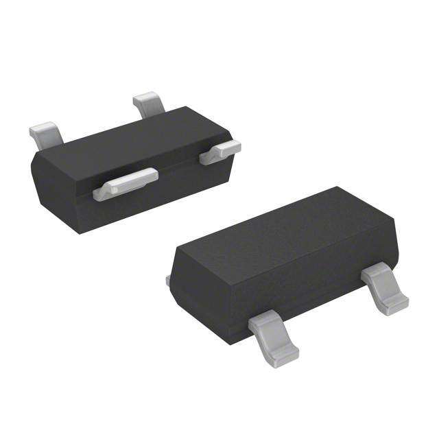
| 描述 | IC OPAMP CURR SENSE SOT23-5 |
| 产品分类 | Linear - Amplifiers - Instrumentation, OP Amps, Buffer Amps |
| 品牌 | Intersil |
| 数据手册 | |
| 产品图片 |
|
| 产品型号 | ISL28005FH20Z-T7A |
| rohs | 无铅 / 符合限制有害物质指令(RoHS)规范要求 |
| 产品系列 | - |
| 产品培训模块 | http://www.digikey.cn/PTM/IndividualPTM.page?site=cn&lang=zhs&ptm=25534http://www.digikey.cn/PTM/IndividualPTM.page?site=cn&lang=zhs&ptm=25593 |
| 供应商器件封装 | SOT-23-5 |
| 其它名称 | ISL28005FH20Z-T7ACT |
| 包装 | 剪切带 (CT) |
| 压摆率 | 0.67 V/µs |
| 增益带宽积 | - |
| 安装类型 | 表面贴装 |
| 封装/外壳 | SC-74A,SOT-753 |
| 工作温度 | -40°C ~ 125°C |
| 应用说明 | |
| 放大器类型 | 电流检测 |
| 标准包装 | 1 |
| 电压-电源,单/双 (±) | 2.7 V ~ 28 V |
| 电压-输入失调 | 1.2mV |
| 电流-电源 | 50µA |
| 电流-输入偏置 | 4.7µA |
| 电流-输出/通道 | 8.7mA |
| 电路数 | 1 |
| 输出类型 | - |


型号:GKZS6
品牌:Honeywell Sensing and Productivity Solutions
产品名称:Labels, Signs, Barriers, Identification
获取报价


- 商务部:美国ITC正式对集成电路等产品启动337调查
- 曝三星4nm工艺存在良率问题 高通将骁龙8 Gen1或转产台积电
- 太阳诱电将投资9.5亿元在常州建新厂生产MLCC 预计2023年完工
- 英特尔发布欧洲新工厂建设计划 深化IDM 2.0 战略
- 台积电先进制程称霸业界 有大客户加持明年业绩稳了
- 达到5530亿美元!SIA预计今年全球半导体销售额将创下新高
- 英特尔拟将自动驾驶子公司Mobileye上市 估值或超500亿美元
- 三星加码芯片和SET,合并消费电子和移动部门,撤换高东真等 CEO
- 三星电子宣布重大人事变动 还合并消费电子和移动部门
- 海关总署:前11个月进口集成电路产品价值2.52万亿元 增长14.8%


PDF Datasheet 数据手册内容提取
DATASHEET ISL28005 FN6973 Micropower, Rail-to-Rail Input Current Sense Amplifier with Voltage Output Rev 5.00 October 24, 2013 The ISL28005 is a micropower, uni-directional high-side and Features low-side current sense amplifier featuring a proprietary rail-to- rail input current sensing amplifier. The ISL28005 is ideal for • Low Power Consumption. . . . . . . . . . . . . . . . . . . . . . .50µA,Typ high-side current sense applications where the sense voltage • Supply Range . . . . . . . . . . . . . . . . . . . . . . . . . . . . . .2.7V to 28V is usually much higher than the amplifier supply voltage. The • Wide Common Mode Input. . . . . . . . . . . . . . . . . . . . 0V to 28V device can be used to sense voltages as high as 28V when operating from a supply voltage as low as 2.7V. The • Fixed Gain Versions micropower ISL28005 consumes only 50µA of supply current - ISL28005-100 . . . . . . . . . . . . . . . . . . . . . . . . . . . . . . 100V/V when operating from a 2.7V to 28V supply. - ISL28005-50 . . . . . . . . . . . . . . . . . . . . . . . . . . . . . . . . 50V/V The ISL28005 features a common-mode input voltage range - ISL28005-20 . . . . . . . . . . . . . . . . . . . . . . . . . . . . . . . . 20V/V from 0V to 28V. The proprietary architecture extends the input • Operating Temperature Range. . . . . . . . . . .-40°C to +125°C voltage sensing range down to 0V, making it an excellent choice for low-side ground sensing applications. The benefit of • Package . . . . . . . . . . . . . . . . . . . . . . . . . . . . . . . . . 5 Ld SOT-23 this architecture is that a high degree of total output accuracy Applications is maintained over the entire 0V to 28V common mode input voltage range. • Power Management/Monitors The ISL28005 is available in fixed (100V/V, 50V/V and 20V/V) • Power Distribution and Safety gains in the space saving 5 Ld SOT-23 package. The parts • DC/DC, AC/DC Converters operate over the extended temperature range from -40°C to • Battery Management/Charging +125°C. • Automotive Power Distribution Related Literature • See AN1531 for “ISL28005 Evaluation Board User’s Guide” • See AN1567 for “ISL28005, ISL28006 Unidirectional Current Sense Amplifiers” SENSE +12VDC +12VDC RSENSE OUTPUT 1.8 - +5VDC VRS+ ISL28005 ISENSE 1.6 +12VDC + 1.4 SENSE VTH(L-H) = 1.52V +5VDC 1.2 +5VDC RSENSE - +5VDC OUTPUT S (V) 1.0 VTH(H-L) = 1.23V ISL28005 ISENSE LT 0.8 + +5VDC VO 0.6 VOUT (G=100) SENSE +1.0VDC +1.0VDC 0.4 G100, VOUT = 1V RSENSE OUTPUT G50, VOUT = 500mV MULTIPLE - +5VDC 0.2 G20, VOUT = 200mV OUTPUT ISL28005 ISENSE 0 +1.0VDC POWER SUPPLY + 0 0.2 0.4 0.6 0.8 1.0 1.2 1.4 1.6 1.8 2.0 TIME (ms) GND FIGURE 1. TYPICAL APPLICATION FIGURE 2. HIGH-SIDE AND LOW-SIDE THRESHOLD VOLTAGE FN6973 Rev 5.00 Page 1 of 16 October 24, 2013
ISL28005 Block Diagram VCC I = 2.86µA VSENSE RS+ HIGH-SIDE AND R1 LOW-SIDE gmHI SENSING RS- R2 + OUT 1.35V - Rf VCC IMIRROR R3 R5 Rg gmLO VSENSE R4 GND Pin Configuration Pin Descriptions ISL28005 ISL28005 PIN (5 LD SOT-23) (5 ld SOT-23) NAME DESCRIPTION TOP VIEW 1 GND Power Ground GND 1 5 RS- 2 OUT Amplifier Output OUT 2 FIXED 3 VCC Positive Power Supply GAIN 4 RS+ Sense Voltage Non-inverting Input VCC 3 4 RS+ 5 RS- Sense Voltage Inverting Input VCC RS- CCAAPPAACCIITTIIVVEELLYY CCOOUUPPLLEEDD OUT EESSDD CCLLAAMMPP RS+ GND FN6973 Rev 5.00 Page 2 of 16 October 24, 2013
ISL28005 Ordering Information PACKAGE PART NUMBER Tape & Reel PKG. (Notes 1, 2, 3) GAIN PART MARKING (Pb-Free) DWG. # ISL28005FH100Z-T7 100V/V BDEA (Note 4) 5 Ld SOT-23 P5.064A ISL28005FH100Z-T7A 100V/V BDEA (Note 4) 5 Ld SOT-23 P5.064A ISL28005FH50Z-T7 50V/V BDDA (Note 4) 5 Ld SOT-23 P5.064A ISL28005FH50Z-T7A 50V/V BDDA (Note 4) 5 Ld SOT-23 P5.064A ISL28005FH20Z-T7 20V/V BDCA (Note 4) 5 Ld SOT-23 P5.064A ISL28005FH20Z-T7A 20V/V BDCA (Note 4) 5 Ld SOT-23 P5.064A ISL28005FH-100EVAL1Z 100V/V Evaluation Board ISL28005FH-50EVAL1Z 50V/V Evaluation Board ISL28005FH-20EVAL1Z 20V/V Evaluation Board NOTES: 1. Please refer to TB347 for details on reel specifications. 2. These Intersil Pb-free plastic packaged products employ special Pb-free material sets, molding compounds/die attach materials, and 100% matte tin plate plus anneal (e3 termination finish, which is RoHS compliant and compatible with both SnPb and Pb-free soldering operations). Intersil Pb-free products are MSL classified at Pb-free peak reflow temperatures that meet or exceed the Pb-free requirements of IPC/JEDEC J STD-020. 3. For Moisture Sensitivity Level (MSL), please see device information page for ISL28005. For more information on MSL please see techbrief TB363. 4. The part marking is located on the bottom of the part. FN6973 Rev 5.00 Page 3 of 16 October 24, 2013
ISL28005 Absolute Maximum Ratings Thermal Information Max Supply Voltage . . . . . . . . . . . . . . . . . . . . . . . . . . . . . . . . . . . . . . . . . ..28V Thermal Resistance (Typical) JA (°C/W) JC (°C/W) Max Differential Input Current . . . . . . . . . . . . . . . . . . . . . . . . . . . . . . ..20mA 5 Ld SOT-23 (Notes 5, 6) . . . . . . . . . . . . . . . 190 90 Max Differential Input Voltage . . . . . . . . . . . . . . . . . . . . . . . . . . . . . . ..±0.5V Maximum Storage Temperature Range . . . . . . . . . . . . . .-65°C to +150°C Max Input Voltage (RS+, RS-) . . . . . . . . . . . . . . . . . . . . . . . GND-0.5V to 30V Maximum Junction Temperature (TJMAX) . . . . . . . . . . . . . . . . . . . . .+150°C Max Input Current for Input Voltage <GND -0.5V . . . . . . . . . . . . . . . ±20mA Pb-Free Reflow Profile . . . . . . . . . . . . . . . . . . . . . . . . . . . . . . . see link below Output Short-Circuit Duration . . . . . . . . . . . . . . . . . . . . . . . . . . . . . Indefinite http://www.intersil.com/pbfree/Pb-FreeReflow.asp ESD Rating Human Body Model . . . . . . . . . . . . . . . . . . . . . . . . . . . . . . . . . . . . . . . . 4kV Recommended Operating Conditions Machine Model. . . . . . . . . . . . . . . . . . . . . . . . . . . . . . . . . . . . . . . . . . .200V Charged Device Model. . . . . . . . . . . . . . . . . . . . . . . . . . . . . . . . . . . . .1.5kV Ambient Temperature Range (TA) . . . . . . . . . . . . . . . . . . .-40°C to +125°C CAUTION: Do not operate at or near the maximum ratings listed for extended periods of time. Exposure to such conditions may adversely impact product reliability and result in failures not covered by warranty. NOTES: 5. is measured with the component mounted on a high effective thermal conductivity test board in free air. See Tech Brief TB379 for details. JA 6. For JC, the “case temp” location is taken at the package top center. Electrical Specification VCC = 12V, VRS+ = 0V to 28V, VSENSE = 0V, RLOAD = 1MΩ, TA = +25°C unless otherwise specified. Boldface limits apply over the operating temperature range, -40°C to +125°C. Temperature data established by characterization. MIN MAX PARAMETER DESCRIPTION CONDITIONS (Note 7) TYP (Note 7) UNIT VOS Input Offset Voltage VCC = VRS+ = 12V, -500 60 500 µV (Notes 8, 9) VS=20mVto=100mV -500 500 VCC = 12V, VRS+ = 0.2V, VS=20mV, -3 -1.2 3 mV VS = 100mV -3.3 3.3 IRS+, IRS - Leakage Current VCC = 0V, VRS+ = 28V 0.041 1.2 µA 1.5 IRS+ Gain = 100 + Input Bias Current VRS+ = 2V, VSENSE = 5mV 4.7 6 µA 7 VRS+ = 0V, VSENSE = 5mV -500 -425 nA -600 Gain = 50, Gain = 20 +Input Bias Current VRS+ = 2V, VSENSE = 5mV 4.7 6 µA 8 VRS+ = 0V, VSENSE = 5mV -700 -432 nA -840 IRS - Input Bias Current VRS+ = 2V, VSENSE = 5mV 5 50 nA 75 VRS+ = 0V, VSENSE = 5mV -125 -45 nA -130 CMRR Common Mode Rejection Ratio VRS+ = 2V to 28V 105 115 dB PSRR Power Supply Rejection Ratio VCC = 2.7V to 28V, VRS+ = 2V 90 105 dB VFS Full-scale Sense Voltage VCC = 28V, VRS+ = 0.2V, 12V 200 mV G Gain ISL28005-100 100 V/V (Note 8) ISL28005-50 50 V/V ISL28005-20 20 V/V FN6973 Rev 5.00 Page 4 of 16 October 24, 2013
ISL28005 Electrical Specification VCC = 12V, VRS+ = 0V to 28V, VSENSE = 0V, RLOAD = 1MΩ, TA = +25°C unless otherwise specified. Boldface limits apply over the operating temperature range, -40°C to +125°C. Temperature data established by characterization. (Continued) MIN MAX PARAMETER DESCRIPTION CONDITIONS (Note 7) TYP (Note 7) UNIT GA Gain = 100 Gain Accuracy VCC = VRS+ = 12V, VSENSE=20mV to -2 2 % (Note 10) 100mV -3 3 VCC = 12V, VRS+ = 0.1V, -0.25 % VSENSE=20mV to 100mV Gain = 50, Gain = 20 Gain Accuracy VCC = VRS+ = 12V, VSENSE=20mV to -2 2 % (Note 10) 100mV -3 3 VCC = 12V, VRS+ = 0.1V, -3 -0.31 3 % VSENSE=20mV to 100mV -4 4 VOA Gain = 100 Total Output Accuracy VCC = VRS+ = 12V, VSENSE=100mV -2.5 2.5 % (Note 11) -2.7 2.7 VCC = 12V, VRS+ = 0.1V, -1.25 % VSENSE=100mV Gain = 50, Gain = 20 Total Output VCC = VRS+ = 12V, VSENSE=100mV -2.5 2.5 % Accuracy (Note 11) -2.7 2.7 VCC = 12V, VRS+ = 0.1V, -6 -1.41 6 % VSENSE=100mV -7 7 VOH Output Voltage Swing, High IO = -500µA, VCC = 2.7V 39 50 mV VCC - VOUT VSENSE = 100mV VRS+ = 2V VOL Output Voltage Swing, Low IO = 500µA, VCC = 2.7V 30 50 mV VOUT VSENSE = 0V, VRS+ = 2V ROUT Output Resistance VCC = VRS+ = 12V, VSENSE=100mV 6.5 IOUT = 10µA to 1mA ISC+ Short Circuit Sourcing Current VCC = VRS+ = 5V, RL = 10Ω 4.8 mA ISC- Short Circuit Sinking Current VCC = VRS+ = 5V, RL = 10Ω 8.7 mA ICC Gain = 100 VRS+ > 2V, VSENSE = 5mV 50 59 µA Supply Current 62 Gain = 50, 20 VRS+ > 2V, VSENSE = 5mV 50 62 µA Supply Current 63 VCC Supply Voltage Guaranteed by PSRR 2.7 28 V SR Gain = 100 Slew Rate Pulse on RS+pin, 0.58 0.76 V/µs VOUT = 8VP-P (see Figure 25) Gain = 50 Slew Rate Pulse on RS+pin, 0.58 0.67 V/µs VOUT = 8VP-P (see Figure 25) Gain = 20 Slew Rate Pulse on RS+pin, 0.50 0.67 V/µs VOUT = 3.5VP-P (see Figure 25) BW-3dB Gain = 100 VRS+ = 12V, 0.1V, VSENSE=100mV 110 kHz -3dB Bandwidth Gain = 50 VRS+ = 12V, 0.1V, VSENSE=100mV 160 kHz -3dB Bandwidth Gain = 20 VRS+ = 12V, 0.1V, VSENSE=100mV 180 kHz -3dB Bandwidth FN6973 Rev 5.00 Page 5 of 16 October 24, 2013
ISL28005 Electrical Specification VCC = 12V, VRS+ = 0V to 28V, VSENSE = 0V, RLOAD = 1MΩ, TA = +25°C unless otherwise specified. Boldface limits apply over the operating temperature range, -40°C to +125°C. Temperature data established by characterization. (Continued) MIN MAX PARAMETER DESCRIPTION CONDITIONS (Note 7) TYP (Note 7) UNIT ts Output Settling Time to 1% of Final Value VCC = VRS+ = 12V, VOUT = 10V step, 15 µs VSENSE >7mV VCC = VRS+ = 0.2V, VOUT = 10V step, 20 µs VSENSE >7mV Capacitive-Load Stability No sustained oscillations 300 pF ts Power-up Power-Up Time to 1% of Final Value VCC = VRS+ = 12V, VSENSE=100mV 15 µs VCC = 12V, VRS+ = 0.2V 50 µs VSENSE = 100mV Saturation Recovery Time VCC = VRS+ = 12V, VSENSE=100mV, 10 µs overdrive NOTES: 7. Compliance to datasheet limits is assured by one or more methods: production test, characterization and/or design. 8. DEFINITION OF TERMS: • VSENSEA = VSENSE @100mV • VSENSEB = VSENSE @20mV • VOUTA = VOUT@VSENSEA = 100mV • VOUTB = VOUT@VSENSEB = 20mV VOUTA–VOUTB • G = GAIN = -------------------------------------------------------------- VSENSEA–VSENSEB V A OUT 9. VOS is extrapolated from the gain measurement.VOS = VSENSEA–--------G------------ 10. % Gain Accuracy = GA =G-----M-----E----A----S----U----R----E----D-----–-----G-----E----X----P----E---C-----T---E----D---100 GEXPECTED 11. Output Accuracy % VOA = -V----O-----U-----T----M-----E---–-A---VS----OU----R-U----E-T---D-E----X–----PV----E-O--C---U--T---TE----ED----X---P----E----C----T----E----D---100where VOUT = VSENSE X GAIN and VSENSE = 100mV Typical Performance Curves VCC = 12V, RL = 1M, unless otherwise specified. 12 12 GAIN 100 GAIN 100 10 10 8 8 V) V) (UT 6 (UT 6 O O V V 4 4 2 2 0 0 0 10 20 30 40 50 60 70 80 90 100 0 10 20 30 40 50 60 70 80 90 100 TIME (µs) TIME (µs) FIGURE 3. LARGE SIGNAL TRANSIENT RESPONSE VRS+ = 0.2V, FIGURE 4. LARGE SIGNAL TRANSIENT RESPONSE VRS+ = 12V, VSENSE = 100mV VSENSE = 100mV FN6973 Rev 5.00 Page 6 of 16 October 24, 2013
ISL28005 Typical Performance Curves VCC = 12V, RL = 1M, unless otherwise specified. (Continued) 1.8 2.4 12 VRS+ 1.6 VRS+ 2.0 10 1.4 VOUT (G = 100) VTH(L-H) = 1.52V 1.2 1.6 8 OLTS (V) 01..80 VOUTV T(GH (=H -1L0) 0=) 1.23V V (V)RS+1.2 RVCL C= =1M 12V 6 V (V)OUT V 0.6 0.8 4 G100, VOUT = 2V 0.4 G100, VOUT = 1V G50, VOUT = 1V G50, VOUT = 500mV 0.4 G20, VOUT = 400mV 2 0.2 G20, VOUT = 200mV 0 0 0 0 0.2 0.4 0.6 0.8 1.0 1.2 1.4 1.6 1.8 2.0 0 0.2 0.4 0.6 0.8 1.0 1.2 1.4 1.6 1.8 2.0 TIME (ms) TIME (ms) FIGURE 5. HIGH-SIDE and LOW-SIDE THRESHOLD VOLTAGE FIGURE 6. VOUT vs VRS+, VSENSE = 20mV TRANSIENT RESPONSE VRS+(L-H) and VRS+(H-L), VSENSE= 10mV 0.2 45 GAIN 100 %) 35 GAIN 100 Y ( 0.0 C 25 A R -0.2 NT ACCU -0.4 +25°C AIN (dB) 155 VRS+= 100mV E G -5 C -0.6 -40°C V PEROA-0.8 +125°C --2155 VAVVCS EC=N =1S 0E102 =V 100mV VRS+ = 12V RL = 1M -1.0 -35 1µ 10µ 100µ 1m 10m 10 100 1k 10k 100k 1M IOUT(A) FREQUENCY (Hz) FIGURE 7. NORMALIZED VOA vs IOUT FIGURE 8. GAIN vs FREQUENCY VRS+= 100mV/12V, VSENSE = 100mV, VOUT = 250mVP-P 50 220 40 1000pF 180 NO CL 30 100pF 140 100pF 4.7nF 100 1000pF AIN (dB) 12000 10nF NO CL HASE (°) -262000 10n4F.7 nF G P -60 -10 VCC = 5V -100 VCC = 5V -20 AVVR S=- 1=0 30V -140 AVVR S=- 1=0 30V -30 VOUT = 400mVP-P -180 VOUT = 400mVP-P -40 -220 1k 10k 100k 1M 1k 10k 100k 1M FREQUENCY (Hz) FREQUENCY (Hz) FIGURE 9. CAPACITIVE LOAD DRIVE GAIN vs FREQUENCY FIGURE 10. CAPACITIVE LOAD DRIVE PHASE vs FREQUENCY FN6973 Rev 5.00 Page 7 of 16 October 24, 2013
ISL28005 Typical Performance Curves VCC = 12V, RL = 1M, unless otherwise specified. (Continued) 0.2 45 GAIN 50 GAIN 50 %) 35 Y ( 0.0 C 25 A R -0.2 CU B) 15 NT AC -0.4 +25°C AIN (d 5 VRS+= 100mV E G -5 V PERCOA--00..86 +-14205°°CC --2155 VAVVCS EC=N =5S 0E12 =V 100mV VRS+ = 12V RL = 1M -1.0 -35 1µ 10µ 100µ 1m 10m 10 100 1k 10k 100k 1M IOUT(A) FREQUENCY (Hz) FIGURE 11. NORMALIZED VOA vs IOUT FIGURE 12. GAIN vs FREQUENCY VRS+= 100mV/12V, VSENSE = 100mV, VOUT = 250mVP-P 50 220 VCC = 5V 40 180 VRS- = 3V 1000pF 30 1000pF 140 AV = 50 NO CL 100 VOUT = 400mVP-P 20 4.7nF 100pF 100pF AIN (dB) 100 10nF NO CL HASE (°) -226000 104n.F7 nF G P -60 -10 VCC = 5V -100 -20 VRS- = 3V AV = 50 -140 -30 VOUT = 400mVP-P -180 -40 -220 1k 10k 100k 1M 1k 10k 100k 1M FREQUENCY (Hz) FREQUENCY (Hz) FIGURE 13. CAPACITIVE LOAD DRIVE GAIN vs FREQUENCY FIGURE 14. CAPACITIVE LOAD DRIVE PHASE vs FREQUENCY 0.2 45 GAIN 20 GAIN 20 %) 35 Y ( 0.0 C 25 A R -0.2 CCU -40°C dB) 15 VRS+= 100mV NT A -0.4 +25°C AIN ( 5 E G -5 RC -0.6 VCC = 12V VRS+ = 12V V PEOA-0.8 --2155 AVVS E=N 2S0E = 100mV +125°C RL = 1M -1.0 -35 1µ 10µ 100µ 1m 10m 10 100 1k 10k 100k 1M IOUT(A) FREQUENCY (Hz) FIGURE 15. NORMALIZED VOA vs IOUT FIGURE 16. GAIN vs FREQUENCY VRS+ = 100mV/12V, VSENSE = 100mV, VOUT = 250mVP-P FN6973 Rev 5.00 Page 8 of 16 October 24, 2013
ISL28005 Typical Performance Curves VCC = 12V, RL = 1M, unless otherwise specified. (Continued) 40 220 180 30 1000pF 100pF 140 20 100pF 100 NO CL NO CL AIN (dB) 100 4.7nF HASE (°) -262000 104n.7Fn F G -10 10nF P -60 -20 VCC = 5V -100 VCC = 5V 1000pF VRS- = 3V -140 VRS- = 3V -30 AV = 20 AV = 20 VOUT = 400mVP-P -180 VOUT = 400mVP-P -40 -220 1k 10k 100k 1M 1k 10k 100k 1M FREQUENCY (Hz) FREQUENCY (Hz) FIGURE 17. CAPACITIVE LOAD DRIVE GAIN vs FREQUENCY FIGURE 18. CAPACITIVE LOAD DRIVE PHASE vs FREQUENCY 15 20 T (uA) 10 IRS+ uA) 15 IRS+ EN 5 T ( 10 R N UR RE VCC = 12V T BIAS C -05 VCC = 12V BIAS CUR 05 ARVVRL S==- 21=0M 12V INPU -10 ARVVRL S==- 21=0M 0V IRS+ INPUT -5 IRS+ -15 -10 0 50 100 150 200 250 0 50 100 150 200 250 DIFFERENTIAL VOLTAGE RS+ TO RS- (mV) DIFFERENTIAL VOLTAGE RS+ TO RS- (mV) FIGURE 19. LOW-SIDE CURRENT SENSING INPUT BIAS CURRENTS FIGURE 20. HIGH-SIDE CURRENT SENSING INPUT BIAS CURRENTS Test Circuits and Waveforms VCC VR1 VCC ICC R1 + RS+ OUT + RS+ VRS++ VSENSE - RS- VRS++ VSENSE- R2 RS- OUT - GND 1M RL VOUT - GND 1M RL VOUT VR2 FIGURE 21. ICC, VOS, VOA, CMRR, PSRR, GAIN ACCURACY FIGURE 22. INPUT BIAS CURRENT, LEAKAGE CURRENT FN6973 Rev 5.00 Page 9 of 16 October 24, 2013
ISL28005 Test Circuits and Waveforms (Continued) VCC SIGNAL GENERATOR VCC RS+ OUT RS+ RS- OUT VRS+ VSENSE RS- GND VRS+ VRS- 1M RL VOUT GND1M RL VOUT PULSE GENERATOR FIGURE 23. SLEW RATE, ts, SATURATION RECOVERY TIME FIGURE 24. GAIN vs FREQUENCY VCC RS+ OUT RS- VRS+ GND 1M RL VOUT PULSE GENERATOR FIGURE 25. SLEW RATE Applications Information supply current from the input source through the RS+ terminal. When the sense voltage at RS+ drops below the 1.35V threshold, Functional Description the gmLO amplifier is enabled for Low Side current sensing. The gmLO input bias current reverses, flowing out of the RS- pin. The ISL28005-20, ISL28005-50 and ISL28005-100 are single Since the gmLO amplifier is sensing voltage around ground, it supply, uni-directional current sense amplifiers with fixed gains cannot source current to R5. A current mirror referenced off Vcc of 20V/V, 50V/V and 100V/V respectively. supplies the current to the second stage for generating a ground The ISL28005 is a 2-stage amplifier. Figure 26 shows the active referenced output voltage. See Figures 19 and 20 for typical circuitry for high-side current sense applications where the sense input bias currents for High and Low side current sensing. voltage is between 1.35V to 28V. Figure27 shows the active circuitry for ground sense applications where the sense voltage is between 0V to 1.35V. The first stage is a bi-level trans-conductance amp and level translator. The gm stage converts the low voltage drop (VSENSE) sensed across an external milli-ohm sense resistor, to a current (@ gm = 21.3µA/V). The trans-conductance amplifier forces a current through R1 resulting to a voltage drop across R1 that is equal to the sense voltage (VSENSE). The current through R1 is mirrored across R5 creating a ground-referenced voltage at the input of the second amplifier equal to VSENSE. The second stage is responsible for the overall gain and frequency response performance of the device. The fixed gains (20, 50, 100) are set with internal resistors Rf and Rg. The only external component needed is a current sense resistor (typically 0.001 to 0.01, 1W to 2W). The transfer function is given in Equation 1. VOUT = GAINISRS+VOS (EQ. 1) Where ISRS is the product of the load current and the sense resistor and is equal to VSENSE. When the sensed input voltage is >1.35V, the gmHI amplifier path is selected and the input gm stage derives its ~2.86µA FN6973 Rev 5.00 Page 10 of 16 October 24, 2013
ISL28005 VCC OPTIONAL I = 2.86µA FILTER CAPACITOR VSENSE IS RS+ HIGH-SIDE + R1 SENSING RS VSENSE gmHI VRS+ = 2V TO 28V - VCC = 2V to 28V RS- R2 + OPTIONAL OUT TRANSIENT 1.35V - Rf PROTECTION IMIRROR R3 gmLO ‘VSENSE R5 Rg LOAD R4 GND FIGURE 26. HIGH-SIDE CURRENT DETECTION VCC = 2V TO 28V VCC OPTIONAL I = 2.86µA FILTER CAPACITOR VSENSE IS RS+ LOW-SIDE + R1 SENSING RS VSENSE gmHI VRS+= 0V TO 28V - RS- R2 + LOAD OPTIONAL OUT TPRRAONTSEICETNIOTN 1.35V VCC IMIRROR - Rf R3 gmLO R5 Rg VSENSE R4 GND FIGURE 27. LOW-SIDE CURRENT DETECTION FN6973 Rev 5.00 Page 11 of 16 October 24, 2013
ISL28005 Hysteretic Comparator value of 100Ω will provide protection for a 2V transient with the maximum of 20mA flowing through the input while adding only The input trans-conductance amps are under control of a an additional 13µV (worse case over-temperature) of VOS. Refer hysteretic comparator operating from the incoming source to the following formula: voltage on the RS+ pin (see Figure 28). The comparator monitors the voltage on RS+ and switches the sense amplifier from the ((RP x IRS-) = (100x 130nA) = 13µV) low-side gm amp to the high-side gm amplifier whenever the Switching applications can generate voltage spikes that can input voltage at RS+ increases above the 1.35V threshold. overdrive the amplifier input and drive the output of the amplifier Conversely, a decreasing voltage on the RS+ pin, causes the into the rails, resulting in a long overload recovery time. hysteric comparator to switch from the high-side gm amp to the low-side gm amp as the voltage decreases below 1.35V. It is that Capacitors CM and CD filter the common mode and differential voltage spikes. low-side sense gm amplifier that gives the ISL28005 the proprietary ability to sense current all the way to 0V. Negative Error Sources voltages on the RS+ or RS- are beyond the sensing voltage range of this amplifier. There are 3 dominant error sources: gain error, input offset voltage error and Kelvin voltage error (see Figure29). The gain 0.5 error is dominated by the internal resistance matching 0.4 tolerances. The remaining errors appear as sense voltage errors 0.3 %) 0.2 at the input to the amplifier. They are VOS of the amplifier and Y ( 0.1 Kelvin voltage errors. If the transient protection resistor is added, AC 0 an additional VOS error can result from the IxR voltage due to R input bias current. The limiting resistor should only be added to U -0.1 CC -0.2 the RS- input, due to the high-side gm amplifier (gmHI) sinking A several micro amps of current through the RS+ pin. -0.3 -0.4 Layout Guidelines -0.5 0 0.2 0.4 0.6 0.8 1.0 1.2 1.4 1.6 1.8 2.0 VRS+ (V) Kelvin Connected Sense Resistor FIGURE 28. GAIN ACCURACY vs VRS+ = 0V TO 2V The source of Kelvin voltage errors is illustrated in Figure29. The resistance of 1/2 oz. copper is ~1m per square with a TC of Typical Application Circuit ~3900ppm/°C (0.39%/°C). When you compare this unwanted parasitic resistance with the total of 1m to 10m resistance of the Figure 30 shows the basic application circuit and optional sense resistor, it is easy to see why the sense connection must be protection components for switched-load applications. For chosen very carefully. For example, consider a maximum current of applications where the load and the power source is permanently connected, only an external sense resistor is needed. For 20A through a 0.005sense resistor, generating a VSENSE = 0.1 and a full scale output voltage of 10V (G=100). Two side contacts applications where fast transients are caused by hot plugging the source or load, external protection components may be needed. of only 0.25 square per contact puts the VSENSE input about 0.5x 1m away from the resistor end capacitor. If only 10A the 20A total The external current limiting resistor (RP) in Figure 30 may be current flows through the kelvin path to the resistor, you get an error required to limit the peak current through the internal ESD voltage of 10mV (10Ax0.5sq x 0.001/sq. = 10mV) added to the diodes to < 20mA. This condition can occur in applications that 100mV sense voltage for a sense voltage error of 10% experience high levels of in-rush current causing high peak (0.110V-0.1)/0.1V)x 100. voltages that can damage the internal ESD diodes. An RP resistor CUCCRuuRrrErreeNnnTtt SSSEeeNnnssSeeE RRReeEssSiissISttooTOrrR CCooppppeerr TTrraaccee 1/2 Oz COPPER TRACE 1m11Ω ttoo T O1100 1mm0OOmΩ 33001mmmOOΩ// SS/SqqQ.. NONNNoo-nnU--NuunnIFiiffOooRrrmmM CUCCRuuRrrrrEeeNnnTtt FFFllLooOwwW CURCCRuuErrNrreeTnn Ott UOOTuu tt CCCUuuRrrRrreeEnnNttT II nnIN PPPCCC BBBOooAaaRrrddD KKKEeeLllvvViiInnN VV VSSSCC CooOnnNttaaTccAttCssTS FIGURE 29. PC BOARD CURRENT SENSE KELVIN CONNECTION FN6973 Rev 5.00 Page 12 of 16 October 24, 2013
ISL28005 2.7VDC TO 28VDC VCC I = 2.86µA RS+ (1mΩ RS 0T.1OΩ) CD gmHI RS- CM + RP OUT 1.35V - + 0.1VDC TO - 28VDC gmLO LOAD GND FIGURE 30. TYPICAL APPLICATION CIRCUIT Overall Accuracy (V %) where: OA VOA is defined as the total output accuracy Referred-to-Output • PDMAXTOTAL is the sum of the maximum power dissipation of (RTO). The output accuracy contains all offset and gain errors, at each amplifier in the package (PDMAX) a single output voltage. Equation 2 is used to calculate the % • PDMAX for each amplifier can be calculated using Equation 5: total output accuracy. V VOA = 100V-----O----U----T----a----cV---t-O-u----Ua----Tl---–-e---xV---p--O--e--U--c--T--t--e-e---dx---p----e----c---t--e----d-- (EQ. 2) PDMAX = VSIqMAX+VS - VOUTMAX-----O----U--R--T---L-M-----A----X-- (EQ. 5) where: where • TMAX = Maximum ambient temperature VOUT Actual = VSENSE x GAIN •JA = Thermal resistance of the package Example: Gain = 100, For 100mV VSENSE input we measure 10.1V. The overall accuracy (VOA) is 1% as shown in Equation 3. • PDMAX = Maximum power dissipation of 1 amplifier VOA = 1001----0---.--11----0-–----1----0-- = 1percent (EQ. 3) • VCC = Total supply voltage • IqMAX = Maximum quiescent supply current of 1 amplifier Power Dissipation • VOUTMAX = Maximum output voltage swing of the application It is possible to exceed the +150°C maximum junction • RL = Load resistance temperatures under certain load and power supply conditions. It is therefore important to calculate the maximum junction temperature (TJMAX) for all applications to determine if power supply voltages, load conditions, or package type need to be modified to remain in the safe operating area. These parameters are related using Equation 4: T = T + xPD (EQ. 4) JMAX MAX JA MAXTOTAL FN6973 Rev 5.00 Page 13 of 16 October 24, 2013
ISL28005 Revision History The revision history provided is for informational purposes only and is believed to be accurate, but not warranted. Please go to web to make sure you have the latest Rev. DATE REVISION CHANGE October 24, 2013 FN6973.5 Added eight new Typical Performance Curves 1. Av = 100 Capacitive Load Drive Gain vs Freq 2. Av = 100 Capacitive Load Drive Phase vs Freq 3. Av = 50 Capacitive Load Drive Gain vs Freq 4. Av = 50 Capacitive Load Drive Phase vs Freq 5. Av = 20 Capacitive Load Drive Gain vs Freq 6. Av = 20 Capacitive Load Drive Phase vs Freq 7. High Side Operation Input Bias Currents 8. Low Side Operation Input Bias Currents Under Electrical Specifications Table: Changed parameter from Is to Icc to clarify supply current. April 11, 2011 FN6973.4 Corrected location of the load in Figure 27. Moved Load from the ground side of the input sense circuit to the high side of the voltage source. Updated note in Min Max column of spec table from "Parameters with MIN and/or MAX limits are 100% tested at +25°C, unless otherwise specified. Temperature limits established by characterization and are not production tested." to "Compliance to datasheet limits is assured by one or more methods: production test, characterization and/or design." September 2, 2010 FN6973.3 Added -T7A tape and reel package options to Ordering Information Table for all packages. May 12, 2010 FN6973.2 Added Note 4 to Part Marking Column in “Ordering Information” on page3. Corrected hyperlinks in Notes 1 and 3 in “Ordering Information” on page3. Corrected ISL28005 hyperlink in “About Intersil” on page15. April 12, 2010 Added Eval boards to ordering info. April 7, 2010 Added “Related Literature” on page1 Updated Package Drawing Number in the “Ordering Information” on page3 from MDP0038 to P50.64A. Revised package outline drawing from MDP0038 to P5.064A on page16. MDP0038 package contained 2 packages for both the 5 and 6 Ld SOT-23. MDP0038 was obsoleted and the packages were separated and made into 2 separate package outline drawings; P5.064A and P6.064A. Changes to the 5 Ld SOT-23 were to move dimensions from table onto drawing, add land pattern and add JEDEC reference number. February 3, 2010 FN6973.1 -Page1: Edited last sentence of paragraph 2. Moved order of GAIN listings from 20, 50, 100 to 100, 50, 20 in the 3rd paragraph. Under Features ....removed "Low Input Offset Voltage 250µV,max" Under Features .... moved order of parts listing from 20, 50, 100 (from top to bottom) to 100, 50, 20. -Page 3: Removed coming soon on ISL28005FH50Z and ISL28005FH20Z and changes the order or listing them to 100, 50, 20. -Page 5: VOA test. Under conditions column ...deleted “20mV to”. It now reads ... Vsense = 100mV SR test. Under conditions column ..deleted what was there. It now reads ... Pulse on RS+pin, See Figure 25 -Page 6: ts test. Removed Gain = 100 and Gain = 100V/V in both description and conditions columns respectively. -Page 9 Added Figure 25 and adjusted figure numbers to account for the added figure. December 14, 2009 FN6973.0 Initial Release FN6973 Rev 5.00 Page 14 of 16 October 24, 2013
ISL28005 About Intersil Intersil Corporation is a leader in the design and manufacture of high-performance analog, mixed-signal and power management semiconductors. The company's products address some of the largest markets within the industrial and infrastructure, personal computing and high-end consumer markets. For more information about Intersil, visit our website at www.intersil.com. For the most updated datasheet, application notes, related documentation and related parts, please see the respective product information page found at www.intersil.com. You may report errors or suggestions for improving this datasheet by visiting www.intersil.com/en/support/ask-an-expert.html. Reliability reports are also available from our website at http://www.intersil.com/en/support/qualandreliability.html#reliability © Copyright Intersil Americas LLC 2009-2013. All Rights Reserved. All trademarks and registered trademarks are the property of their respective owners. For additional products, see www.intersil.com/en/products.html Intersil products are manufactured, assembled and tested utilizing ISO9001 quality systems as noted in the quality certifications found at www.intersil.com/en/support/qualandreliability.html Intersil products are sold by description only. Intersil may modify the circuit design and/or specifications of products at any time without notice, provided that such modification does not, in Intersil's sole judgment, affect the form, fit or function of the product. Accordingly, the reader is cautioned to verify that datasheets are current before placing orders. Information furnished by Intersil is believed to be accurate and reliable. However, no responsibility is assumed by Intersil or its subsidiaries for its use; nor for any infringements of patents or other rights of third parties which may result from its use. No license is granted by implication or otherwise under any patent or patent rights of Intersil or its subsidiaries. For information regarding Intersil Corporation and its products, see www.intersil.com FN6973 Rev 5.00 Page 15 of 16 October 24, 2013
ISL28005 Package Outline Drawing P5.064A 5 LEAD SMALL OUTLINE TRANSISTOR PLASTIC PACKAGE Rev 0, 2/10 1.90 0-3° D A 0.08-0.20 5 4 PIN 1 INDEX AREA 2.80 3 1.60 3 5 0.15 CD 2x 2 0.20 C (0.60) 2x 0.95 SEE DETAIL X B 0.40 ±0.05 3 END VIEW 0.20M C A-B D TOP VIEW 10° TYP (2 PLCS) 5 0.15 C A-B H 2.90 2x 1.45 MAX C 1.14 ±0.15 (0.25)GAUGE 0.10 C SEATING PLANE PLANE 0.45±0.1 4 SIDE VIEW 0.05-0.15 DETAIL "X" (0.60) (1.20) NOTES: 1. Dimensions are in millimeters. (2.40) Dimensions in ( ) for Reference Only. 2. Dimensioning and tolerancing conform to ASME Y14.5M-1994. 3. Dimension is exclusive of mold flash, protrusions or gate burrs. 4. Foot length is measured at reference to guage plane. 5. This dimension is measured at Datum “H”. 6. Package conforms to JEDEC MO-178AA. (0.95) (1.90) TYPICAL RECOMMENDED LAND PATTERN FN6973 Rev 5.00 Page 16 of 16 October 24, 2013