ICGOO在线商城 > 传感器,变送器 > 磁性传感器 - 罗盘,磁场(模块) > HMR3300

 Datasheet下载
- 型号: HMR3300
- 制造商: Honeywell Solid State Electronics
- 库位|库存: xxxx|xxxx
- 要求:
| 数量阶梯 | 香港交货 | 国内含税 |
| +xxxx | $xxxx | ¥xxxx |
查看当月历史价格
查看今年历史价格
HMR3300产品简介:
ICGOO电子元器件商城为您提供HMR3300由Honeywell Solid State Electronics设计生产,在icgoo商城现货销售,并且可以通过原厂、代理商等渠道进行代购。 HMR3300价格参考¥4071.80-¥4071.80。Honeywell Solid State ElectronicsHMR3300封装/规格:磁性传感器 - 罗盘,磁场(模块), ±2 Gauss, ±60° Compass X, Y, Z 100 µGauss, 0.1° Module (No Case)。您可以下载HMR3300参考资料、Datasheet数据手册功能说明书,资料中有HMR3300 详细功能的应用电路图电压和使用方法及教程。
Honeywell Aerospace的HMR3300磁性传感器是一款高精度、三轴数字磁力计模块,广泛应用于需要精确航向和姿态测量的场景。以下是其主要应用场景:

 1. 航空与航海导航
HMR3300在航空和航海领域中用于提供精确的航向信息。它能够实时测量地球磁场,并结合其他传感器(如加速度计和陀螺仪)进行数据融合,帮助飞机、船只等航行设备确定其相对于地理北极的方向。该传感器具有出色的抗干扰能力和稳定性,能够在复杂的电磁环境中保持高精度。

 2. 无人机与无人驾驶车辆
在无人机和无人驾驶车辆中,HMR3300用于提供稳定的航向参考,确保车辆能够准确地沿着预定路径行驶。它还可以与其他传感器配合使用,提供更全面的姿态信息,帮助车辆实现自动避障、路径规划等功能。此外,HMR3300的低功耗特性使其非常适合电池供电的移动设备。

 3. 机器人定位与导航
对于工业机器人和自主移动机器人(AMR),HMR3300可以作为关键的传感器之一,帮助机器人确定自身位置和方向。通过与GPS、激光雷达等其他传感器结合,HMR3300可以为机器人提供更加可靠的导航能力,尤其在室内或GPS信号不佳的环境中表现出色。

 4. 军事与安防
在军事应用中,HMR3300可用于导弹制导、武器瞄准系统以及士兵携带的便携式导航设备。它的高精度和可靠性使其成为军事装备的理想选择。此外,在安防监控领域,HMR3300可以用于检测异常磁场变化,识别潜在的安全威胁。

 5. 消费电子产品
HMR3300还适用于高端消费电子产品,如智能手表、智能手机和平板电脑中的电子罗盘功能。它可以帮助这些设备提供准确的方向信息,增强用户体验。同时,HMR3300的小型化设计使其易于集成到各种便携式设备中。

总之,HMR3300凭借其高精度、稳定性和抗干扰能力,广泛应用于航空、航海、无人驾驶、机器人、军事和消费电子等多个领域,为各类设备提供了可靠的航向和姿态测量解决方案。
| 参数 | 数值 |
| 产品目录 | |
| 描述 | MODULE DIG COMPASS UART 3 AXIS |
| 产品分类 | |
| 品牌 | Honeywell Microelectronics & Precision Sensors |
| 数据手册 | |
| 产品图片 |
|
| 产品型号 | HMR3300 |
| rohs | 不符合限制有害物质指令(RoHS)规范要求 |
| 产品系列 | HMR |
| 产品培训模块 | http://www.digikey.cn/PTM/IndividualPTM.page?site=cn&lang=zhs&ptm=4082http://www.digikey.cn/PTM/IndividualPTM.page?site=cn&lang=zhs&ptm=26237http://www.digikey.cn/PTM/IndividualPTM.page?site=cn&lang=zhs&ptm=30104 |
| 产品目录页面 | |
| 其它名称 | 342-1032 |
| 分辨率 | 100 µ高斯, 0.1° |
| 封装/外壳 | 模块(无外壳) |
| 接口 | UART,SPI |
| 标准包装 | 1 |
| 测量范围 | ±2 高斯, ±60° |
| 特色产品 | http://www.digikey.cn/product-highlights/cn/zh/honeywell-micro-digital-compassing-solutions/3663 |
| 用于测量 | 制导,间距和卷 |
| 类型 | 数字罗盘 |
| 轴 | X,Y,Z |
| 配用 | /product-detail/zh/HMR3300-DEMO-232/342-1033-ND/396918 |


- 商务部:美国ITC正式对集成电路等产品启动337调查
- 曝三星4nm工艺存在良率问题 高通将骁龙8 Gen1或转产台积电
- 太阳诱电将投资9.5亿元在常州建新厂生产MLCC 预计2023年完工
- 英特尔发布欧洲新工厂建设计划 深化IDM 2.0 战略
- 台积电先进制程称霸业界 有大客户加持明年业绩稳了
- 达到5530亿美元!SIA预计今年全球半导体销售额将创下新高
- 英特尔拟将自动驾驶子公司Mobileye上市 估值或超500亿美元
- 三星加码芯片和SET,合并消费电子和移动部门,撤换高东真等 CEO
- 三星电子宣布重大人事变动 还合并消费电子和移动部门
- 海关总署:前11个月进口集成电路产品价值2.52万亿元 增长14.8%
PDF Datasheet 数据手册内容提取
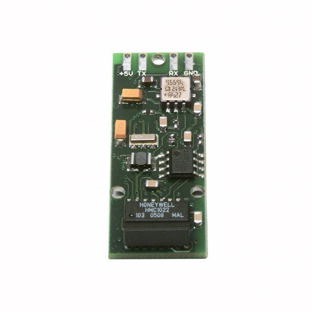
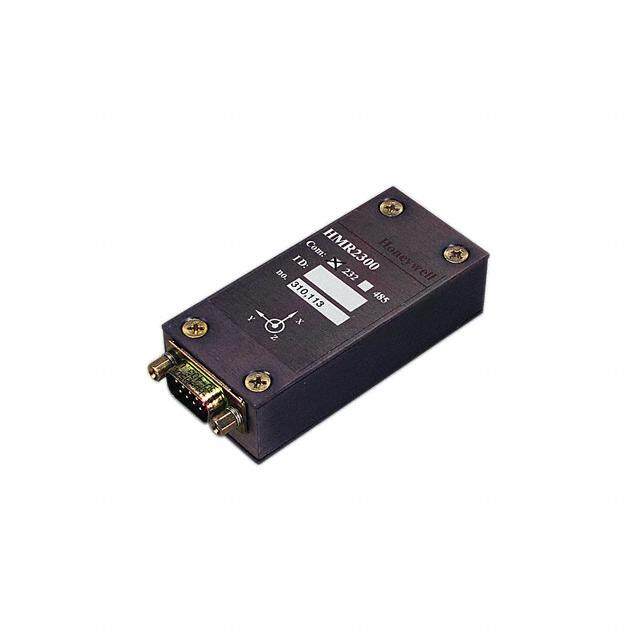
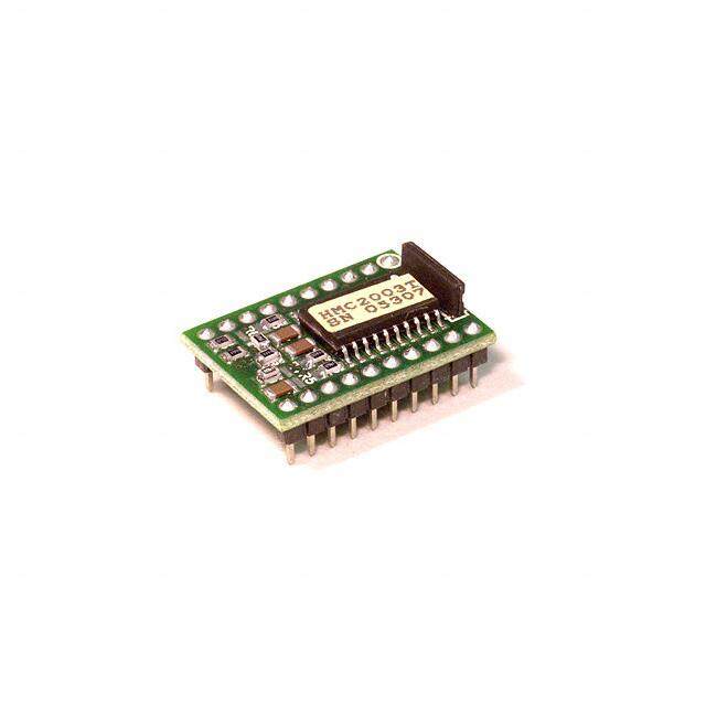
Digital Compass Solutions HMR3200/HMR3300 The Honeywell HMR3200/HMR3300 are digital compass solutions for use in precision heading applications. Honeywell’s magnetoresistive sensors are utilized to provide the reliability and accuracy of these small, solid state compass designs. These compass solutions are designed for generic precision compass integration into customer systems using a 5-voltage logic level serial data interface with commands in ASCII format. The HMR3200 is a two-axis precision compass with three orthogonal magnetoresistive sensors, and can be used in either vertical or horizontal orientations. The HMR3300 includes a MEMS accelerometer for a horizontal three-axis, tilt compensated precision compass for performance up to a ±60° tilt range. Honeywell continues to maintain product excellence and performance by introducing innovative solid-state magnetic sensor solutions. These are highly reliable, top performance products that are delivered when promised. Honeywell’s magnetic sensor solutions provide real solutions you can count on. FEATURES BENEFITS 4 Compact Solution on a 1.0” by 1.5” PCB 4 Small Size and Pin Interface for Daughter/Motherboard Integration 4 Precision Compass Accuracy 4 ±1° at Level Heading Accuracy, ±0.1° Resolution 4 Tilt-Compensated (HMR3300 only) 4 Up to ±60° of Pitch and Roll Angles Using a MEMS Accelerometer 4 0.5° Repeatability 4 Magnetoresistive Sensor Technology for Consistency 4 8 Hz Continuous Update Rate 4 Rapid Heading Computations for Control System Applications 4 Hard-Iron Compensation Routine 4 User Driven Calibration to Null Stray Fields 4 -40° to +85°C Operating Temp Range 4 Consumer and Industrial Environment Uses 4 Demonstration Kit Available 4 Includes RS-232 Motherboard PCB, Cable, 9-volt power supply, PC Demo Software, and a Carrying Case 4 UART and SPI Communication 4 Intuitive Command Language
HMR3200/3300 SPECIFICATIONS Characteristics Conditions Min Typ Max Units Heading Accuracy Level 1.0 deg RMS 0° to ±30° (HMR3300 only) 3.0 ±30° to ±60° (HMR3300 only) 4.0 Resolution 0.1 deg Hysteresis HMR3200 0.1 0.2 deg HMR3300 0.2 0.4 Repeatability HMR3200 0.1 0.2 deg HMR3300 0.2 0.4 Pitch and Roll (HMR3300 only) Range Roll and Pitch Range ± 60 deg Accuracy 0° to ± 30° 0.4 0.5 deg ± 30° to ± 60° 1.0 1.2 Null Accuracy* Level 0.4 deg -20° to +70°C Thermal Hysterisis 1.0 -40° to +85°C Thermal Hysterisis 5.0 Resolution 0.1 deg Hysteresis 0.2 deg Repeatability 0.2 deg Magnetic Field Range Maximum Magnetic Flux Density ± 2 gauss Resolution 0.1 0.5 milli-gauss Electrical Input Voltage Unregulated 6 - 15 volts DC Regulated 4.75 - 5.25 Current HMR3200 18 20 mA HMR3300 22 24 Digital Interface UART ASCII (1 Start, 8 Data, 1 Stop, 2400 - 19200 Baud 0 Parity) User Selectable Baud Rate SPI CKE = 0, CKP = 0 Psuedo Master Update Continuous/Strobed/Averaged HMR3200 15 Hz HMR3300 8 Connector In-Line 8-Pin Block (0.1” spacing) Physical Dimensions Circuit Board Assembly 25.4 x 36.8 x 11 mm Weight HMR3200 7.25 grams HMR3300 7.50 Environment Temperature Operating (HMR3200) -40 - +85 °C Operating (HMR3300) -20 - +70 Storage -55 +125 * Null zeroing prior to use of the HMR3300 and upon exposure to temperature excursions beyond the Operating Temperature limits is required to achieve highest performance. 2 www.honeywell.com
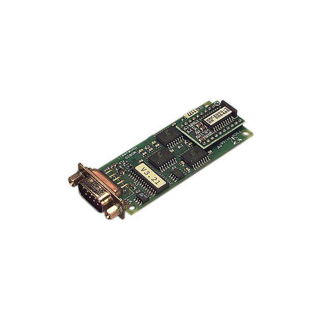
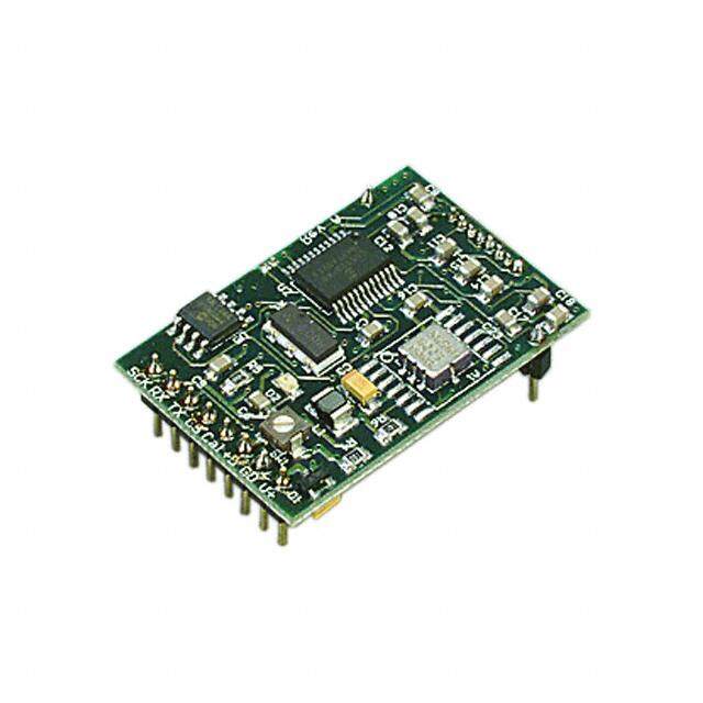
HMR3200/3300 PHYSICAL CHARACTERISTICS The circuit board for the HMR3200/HMR3300 Digital Compassing Solutions is approximately 1.45 by 1 inches. An 8-Pin header protrudes down on the rear edge of the compass circuit board for the user electrical interface to the motherboard. The header pins extend 5/16” below the board plane with the bottom-side mounted magnetic sensor integrated circuits (HMC1021Z and HMC1022) extending 3/16” below the board plane. Components on the top-side have a maximum height of 1/8”. In addition two single pins, identical to the 8 header pins, are placed on the sides toward the forward edge of the circuit board (HMC1021Z is at the magnetic front or north reference). These single pins are for mechanical mounting and do not have electrical connections to the compass electronics. POWER SUPPLY INTERFACE Rotary switch (SW1) is located near pins 6 and 7, and is used to select the customer provided power supply voltage type. The HMR3200/3300 is factory set with this switch fully clockwise, for selection of unregulated input (+6 to+15) voltage from the V+ pin (pin 8). By rotating the switch fully counter-clockwise, users may provide a regulated +5 volt supply to the +5 pin (pin 6) as an alternative. Incorrect switch settings may cause no response or faulty responses. Upon correct power application, light emitting diode D2 turns on for about one second afterwards to indicate the execution of the initialization firmware. Do not use both power inputs simultaneously. Figure 1 shows a typical HMR3200/HMR3300 circuit board assembly with the basic dimensions. 111...444555””” 000...111555””” 888 ...000333777””” 777 SSSWWW111 666 888---PPPIIINNN 555 111...000000””” 444 (((000...111HHH”””EEESSSAAAPPPDDDAAAEEECCCRRRIIINNNGGG))) 333 PP 222 itchitch ...000333777””” 111 Ax Ax isis ...000999444””” RRREEEFFF PPPIIINNNSSS ~~~000...333000”””TTTaaallllll --- +++ (((222))) 111...222222””” +++ FFoorrwwaarrdd DDiirreeccttiioonn RRoollll AAxxiiss --- Figure 1 MOUNTING CONSIDERATIONS The HMR3200/HMR3300 precision compasses use the ten integrated circuit style pins to plug into compatible motherboards for electrical interface, and to be orientated mechanically. The pins are nominally 0.030” in diameter and 0.200 in length. Trimming the pin lengths or removing the pins voids the warranty, as Honeywell can not retest the modified compasses (socketized test fixtures). Wires can be substituted for the pins, but caution should be used in soldering to not damage the pin solder pads. The HMC1021Z part is an 8-pin SIP device that is shipped carefully in a nearly perfectly vertical orientation with respect to the horizontal referenced circuit board. Do not bend or reposition this part, or the factory magnetic calibration will be no longer valid. Should the part be accidentally bent, return for recalibration is possible or align the part vertical to recapture most of the accuracy. Correct flat orientation of the compass modules is with the pins pointing downward. CIRCUIT DESCRIPTION The HMR3200/HMR3300 Digital Compass Solutions include all the basic sensors and electronics to provide a digital indication of heading. The HMR3200 has all three axis of magnetic sensors on board, but allows the user to select which www.honeywell.com 3
HMR3200/3300 pair of sensors for compassing (flat or upright). The HMR3300 uses all three magnetic sensors plus includes an accelerometer to provide tilt (pitch and roll) sensing relative to the board’s horizontal (flat) position. The HMR3200/HMR3300 circuit starts with Honeywell HMC1021Z and HMC1022 single and two-axis magnetic sensors providing X, Y, and Z axis magnetic sensing of the earth’s field. The HMC1022 provides the horizontal components (X and Y), and HMC1021Z provides the vertical (Z) axis component of the incident magnetic field into cartesian magnitudes at orthognal angles. These sensors are supplied power by a constant current source to maintain best accuracy over temperature. The sensor output voltages and constant current sensor supply voltage are provided to a multiplexed 16-bit Analog to Digital Converter (ADC) integrated circuit. A microcontroller integrated circuit periodically queries the multiplexed ADC and performs the offset corrections and computes the heading. This microcontroller also performs the external serial data interface and other housekeeping functions such as the calibration routine. An onboard EEPROM integrated circuit is employed to retain necessary data variables for best performance. For the HMR3200, the three magnetic sensors (XYZ) are included and no accelerometer is present. The *L (level) and *U (upright) are available for horizontal and vertical circuit board orientations respectively. At level, the XY sensors are used to compute heading; and upright, the YZ sensors are used to compute heading. For the HMR3300, an additional pair of data inputs from the ±2g accelerometer (Analog Devices ADXL213) is received by the microcontroller. These tilt inputs (pitch and roll) are added to sensor data inputs to form a complete data set for a three dimensional computation of heading. If the board is held horizontal, the pitch and roll angles are zero and the X and Y sensor inputs dominate the heading equation. When tilted, the Z magnetic sensor plus the accelerometer’s pitch and roll angles enter into heading computation. The power supply for the HMR3200/HMR3300 circuit is regulated +5 volt design allowing the user to directly provide the regulated supply voltage or a +6 to +15 volt unregulated supply voltage. If the unregulated supply voltage is provided, then the linear voltage regulator integrated circuit drops the excess supply voltage to a stable +5 volts. The power supply is a dual ground (analog and digital) system to control internal noise and maximize measurment accuracy. ELECTRICAL INTERFACE PINOUT Pin Number Pin Name Description 1 SCK Synchronous Data Clock (Pulled high in UART mode and left open) 2 RX Receive Data, 5V CMOS Input 3 TX Transmit Data, 5V CMOS Output 4 CS Chip Select (Pulled high in UART mode and left open) 5 Cal Calibration Input (No connection normally, consult for details) 6 +5 +5 Volt Regulated Power Input (SW1 must be fully CCW) 7 GD Logic and Power Return (Ground) 8 V+ Unregulated Power Input (+6 to +15 volts, factory default, SW1 must be CW) APPLICATION NOTES When To Calibrate The HMR3200/HMR3300 comes with an optional user hard-iron calibration routine to null modest intensity hard-iron distortion. For many users in cleaner magnetic environments, the factory calibration will be better and yield more accurate readings than after a user calibration. The calibration routine is not cure-all for nasty magnetic environments. If a needle compass is thrown off from true readings, then it is very likely the HMR3200 and HMR3300 will have poor accuracy too. Most compass error sources come from ferrous metals (steel, iron, nickel, cobalt, etc.) located too close to the compass location and are known as soft-irons creating soft-iron distortion. Soft-iron distortion will change the intensity and direction of the magnetic fields on any nearby compass, and the calibration routine can not remove these flux concentration and bending errors. A good rule of thumb is to keep soft-irons at least two largest dimensions away from the compass. For example, a half-inch stainless steel panhead bolt should be at least an inch away from the HMC1021Z and HMC1022 sensor locations. 4 www.honeywell.com
HMR3200/3300 Other nasty magnetic environments are man-made AC and DC magnetic fields created from nearby motors and high current conductors. These fields should also require compass or source relocation when possible. In some cases, ferrous metal shielding may help if the shield material is thin and far enough away from the compass. Hard-iron distortion can be calibrated out, and is composed of soft-irons that are also magnetized and create remnant (stray) magnetic flux. Classic hard-iron distortion typically comes from large vehicle chassis components and engine blocks that have up to ±2 gauss on the parts. Locating the compass away from hard and soft-irons is the first line of defense to preserve accuracy, and the calibration routine will null out the remaining hard-iron influences. Calibration Procedure For the HMR3200, one complete turn in a level plane is the best way to expose the sensors to all headings to compute the calibration offsets. Since the compass collects data at a 15 samples per second rate, a sample per degree of rotation or slower is a good guideline. If slow turns are not possible, multiple faster turns are a good substitute. The goodness of the calibration or the amount of hard-iron present is found by checking the Xof, Yof, and Zof values after the calibration routine is complete. In known clean magnetic environments, the horizontal values (XY = level, YZ = upright) should be ±200 ADC counts or less in these offset variables. Sending these Xof, Yof, and Zof values back to zero returns the compass to the factory calibration state. The vertical axis values can be zero set or ignored for the HMR3200. For the HMR3300, the above described level turns will calibrate the XY axis’, but the Z-axis must also be calibrated as well One full rotation with as much pitch and roll variation included as application allows. If only mild pitch and roll variations are possible, complete the level rotations, exit the calibration routine, and force the Zof value to zero. Some accuracy maybe lost in this zeroing, but the mild tilt would likely never cause serious tilt-compensation heading error. UART COMMUNICATION PROTOCOL HMR3200/HMR3300 modules communicate through ASCII characters with the * or # characters as start bytes. The data bit format is 1 Start, 8 Data, 1 Stop, and No parity bits. Factory baud rate is set to 19,200. Asynchronous communication has the complete menu of commands. Synchronous communication is limited to direct heading queries and no other commands. POWER-ON/RESET The compasses require a hard power-on transition on the power supply voltage to serve as an internal hardware reset and clock-start. Some bench power supplies may create a soft-start condition and the HMR3200/HMR3300 my react with a constant-on LED illumination if not reset suddenly. An in-line power supply switch (mechanical or electrical) may be required when prototyping to avoid soft-starts. Upon application of power or after a Reset Command, the HMR3200/HMR3300 will run about an 800 milli-second initialization routine to set the onboard hardware and grab EEPROM variables and shadow them in controller RAM locations for operation. The LED will illuminate during the routine and extinguish upon completion. INITIAL STATUS OUTPUT The HMR3200/HMR3300 will begin sending ASCII characters immediately after the initialization routine ends and the LED extinguishes. The first line of text will be the model number of the compass and the internal firmware revision number. For the HMR3300, a second response string will be sent, starting with a # character and either the N, W or A characters. The #N response indicates normal operation and is the always expected response from the HMR3200. The #W and #A responses are only for the HMR3300, and indicate the low temperature warning and alarm environments had been encountered. These responses will be reset to normal when the user sends the pitch and roll re-zero commands to re- calibrate the MEMS accelerometer for best tilt-compensation performance and accurate tilt indications. After initialization, the compasses automatically begin streaming heading or magnetometer output data at 15Hz (HMR3200) or 8Hz (HMR3300). Users must send a start/stop command (*S) to exit continuous streaming data, and to get the controller’s full attention to the next commands. www.honeywell.com 5
HMR3200/3300 OPERATIONAL COMMANDS Syntax: *X<cr><lf> Sends command for an operational mode change. The * prefix indicates command type. A #I response indicates an invalid command was sent. Heading Output Command *H<cr><lf> Selects the Heading output mode (factory set default). This configuration is saved in non-volatile memory. All data are in decimal degrees. Response Format: Heading<cr><lf> (HMR3200 only and 15 times per second) Eg: 235.6<cr><lf> Response Format: Heading, Pitch, Roll<cr><lf> (HMR3300 only and 8 times per second) Eg: 123.4, 18.6, -0.5<cr><lf> Magnetometer Output Command *M<cr><lf> Selects the magnetometer output mode. This configuration is saved in non-volatile memory. All data are in signed decimal values with user calibration offsets included. Response Format: MagX, MagY, MagZ<cr><lf> Eg: 1256, -234, -1894<cr><lf> Compass Orientation (HMR3200 only) *L<cr><lf> Heading calculation is done assuming the compass is level (XY). *U<cr><lf> Heading calculation is done assuming the compass is upright (connector end down) (YZ). These orientation commands are saved in non-volatile memory. Starting and Stopping Data Output *S<cr><lf> The data output will toggle between Start and Stop each time this command is issued (factory set default is Start, first Start/Stop command will stop data output). Continuous data streaming control. Most commands require the compass to be in a stop condition for the controller to immediately execute the desired command. Query Output *Q<cr><lf> Query for a single output response string in the currently selected mode (Magnetometer/Heading). The *Q commands are allowed only in Stop data mode. Query commands allow the user to slow the data flow by requesting each response string. 6 www.honeywell.com
HMR3200/3300 Roll Axis Re-Zero (HMR3300 only) *O<cr><lf> Allows the user to zero the roll output. This command should only be issued when the roll axis is leveled (±0.3°). Clears Alarm or Warning status after command receipt. Pitch Axis Re-Zero (HMR3300 only) *P<cr><lf> Allows the user to zero the pitch output. This command should only be used when the pitch axis is leveled (±0.3°). Clears Alarm or Warning status after command receipt. Averaged Output *A<cr><lf> Same result as the query command except that the data are the result of an averaging of 20 readings. The *A commands are allowed only in Stop data mode. The command response will not occur until the 20 readings accrue (8 per second for the HMR3300, 15 per second for the HMR3200). Split Filter Toggle (HMR3300 only) *F<cr><lf> This command toggles the split filter bit in the configuration status bytes. The parameter setting is saved in the EEPROM immediately, but not in shadowed in RAM. Requires power cycling or a reset command (*R) to activate. A set bit indicates the System Filter only smoothes the accelerometer data (Tilt Filter), and the Magnetic Filter is now active to smooth magnetic sensor data. A cleared filter bit resumes the same smoothing for both the tilt and magnetometer data. Reset *R<cr><lf> Resets compass to power-up condition. A one second initialization routine starts and EEPROM data (non-volatile memory) is uploaded (shadowed) into RAM. Continuous streaming data begins after initialization and status output. User Calibration *C<cr><lf> The command to be issued to enter and exit the calibration mode. Once in the calibration mode, the device will send one or more magnetometer data strings appended by a “C” character to indicate the Calibration Mode operation. Eg. 123,834,1489,C<cr><lf> See the calibration procedure notes earlier in this datasheet. At the completion of the calibration movements, issue another *C<cr><lf> to exit the calibration mode. www.honeywell.com 7
HMR3200/3300 Configuration Commands Syntax: #Dev=±xxxx<cr><lf> Sets parameter value #Dev?<cr><lf> Queries for the parameter value Variation Input (Declination Angle Correction) #Var=±nnnn<cr><lf> where the variation is ± nnn.n degrees Sets the declination angle between magnetic north and geographic north. The declination angle is subtracted from the magnetic north heading computed to create a geographic north heading. Values typically range in the ±25 degree area. For example New York has a -14 degree declination angle, and Los Angles has a +14 degree declination angle. Eg: #Var=-203<cr><lf> sets the declination angle to –20.3 degrees. Eg: #Var=?<cr><lf>returns the declination angle; –20.3 Deviation Input (Platform Angle Correction) #Dev=±nnnn<cr><lf> where the angle is ± nnn.n degrees Sets or returns the angle between compass forward direction and that of the mounting platform. The Deviation angle is subtracted from the predicted heading to compensate for mechanical misalignment. Eg: #Dev=23<cr><lf> sets the deviation angle to +2.3 degrees. Eg: #Dev=?<cr><lf>returns the deviation angle; +2.3 User Magnetic Offset Values (X, Y and Z) #Xof, #Yof, #Zof Sets or returns the user offset values for each magnetic axis. These values are recomputed after a calibration routine. Also fixed offsets can be inserted to correct for known magnetic shifts. Values are in ADC counts. Eg: #Xof=+47<cr><lf> sets the x offset value to +47. Eg: #Xof=?<cr><lf> returns the x offset value; +47. Baud Rate #Bau Sets the compass transmit and recieve baud rate. 19200, 9600, 4800 and 2400 are the only allowed values. Baud rate can not be queried and is sent to the EEPROM to overwrite the present setting. Factory default is 19200. Eg: #XBau=9600<cr><lf> sets the Baud Rate to 9600 after the next Reset command or power cycle. System Filter #SFL Sets and reads the system IIR filter setting. When the Split Filter bit is cleared, this parameter value will become the default value for both Magnetic and Tilt Filters. When the Split Filter bit is set, SFL parameter setting will control the Tilt filter value only. The parameter input is saved in the EEPROM immediately. Requires power cycling or a Reset command (*R) to become effective. The setting of the Split Filter bit can be queried via the #CON? command. Values between 0 and 255 are valid, with a factory default of 3. A good reason to increase the filter value would be in the presence of high mechanical vibration environments. Eg: #SFL=6<cr><lf> Sets the system filter value of 6. 8 www.honeywell.com
HMR3200/3300 Magnetic Filter #MFL The MFL command sets and reads the Magnetic Filter setting. When the Split Filter bit is cleared, this parameter value will default to the value of SFL, the system filter. When the Split Filter bit is set, MFL parameter setting will control the Magnetic Filter value. The parameter input is saved in the EEPROM immediately. Requires power cycling or a Reset command (*R) to become effective. Values between 0 and 255 are valid, with a factory default of 3. A good reason to increase the magnetic filter value would be the presence of AC magnetic fields from nearby conductors or motors. Eg: #SFL=0<cr><lf> Sets the magnetic filter value of zero (no filtering). Configuration #CON? This command queries for the configuration status of the compass module. The output of the configuration value is in decimal representation (in ASCII format) of the two byte configuration status. The 16-bit binary pattern is defined below. bit 15 bit 14 bit 13 bit 12 bit 11 bit 10 bit 9 bit 8 N/A N/A N/A N/A N/A SplitFilter Alarm Warn bit 7 bit 6 bit 5 bit 4 bit 3 bit 2 bit 1 bit 0 N/A N/A 1 N/A H Out N/A Mag Out N/A Parameter Bit Value Effect Name Reported Mag Out 1 Magnetic Sensor Output Sentence selected (X, Y, Z) H Out 1 Heading Output Sentence selected (H, P, R) Device temperature has fallen below -10 C during this session of Warn 1 operation. Rezero pitch and roll to clear after low temp. Device temperature has fallen below -20 C during this session of Alarm 1 operation. Rezero pitch and roll to clear after low temp. SplitFilter 1 Independent Filter values for Magnetic and Tilt are used Eg: #CON? Returns a response of #D=2088<cr><lf> meaning same filters used for magnetic and tilt data (bit 10 clear) and the compass module is sending heading data (bit 3 set). Command Responses These are compass module generated responses to commands issued by the host processor. These responses follow in format to the commands issued. #Dxxx<cr><lf> Returns numeric data requested in decimal format. #I<cr><lf> Invalid command response. Response to any invalid command. SPI Interface SPI operating Mode is as follows: SCK idles low (mode CKP=0, CKE=0) Data Output after falling edge of SCK Data sampled before rising edge of SCK www.honeywell.com 9
HMR3200/3300 Synchronous Communication Protocol The HMR3200/HMR3300 module controls the synchronous clock (SCK) and synchronous data output (SDO) pins and the host controller controls synchronous data input (SDI) and chip select (CS) pins. The host controller shall lower the HMR module’s CS pin for at least 20 microseconds to initiate the SPI communication. In response the HMR module will send the ASCII bit pattern for 's', and the host shall transmit a valid command character simultaneously. The HMR module will evaluate the command character received from the host controller and send the appropriate data if the command is recognized and valid. After transmitting the required data, the HMR module will end the SPI session. If the command is invalid or was not recognized, then the HMR module will transmit ASCII bit pattern for 'e' and end the SPI session. SPI Commands Heading Output: In response to an ASCII H or h command, the HMR3200/HMR3300 shall send two bytes of data. The MSByte is transmitted first. These two bytes represent the integer value equal to 10*Heading. The MSbit is transmitted first for each byte. SCK shall be high for 16, and low for 22 microseconds, respectively. There is a 50 microsecond delay between consecutive bytes transmitted. Command Character Action SPI Data Output Parameter Value H or h Sends heading data 0000 to 3599 Heading: 000.0 to 359.9 Data Representation Heading Output: In response to an H or h command, HMR3200/HMR3300 module shall send two bytes of data. The MSByte is transmitted first. These two bytes represent the integer value equal to 10*Heading. The MSbit is transmitted first for each byte. SPI Timing The SCK shall be high for 16, and low for 22 microseconds, respectively. There is a 50 microsecond delay between consecutive bytes transmitted. SPI Timing Diagram CCSS TThh ~~ 1166µµsseecc SSCCKK TTll ~~ 2222µµsseecc SSDDOO MMSS bbiitt SSDDII SPI He ading Output LS Byte MS Byte Tb = 50µsec 10 www.honeywell.com
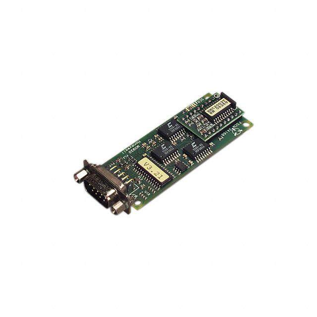
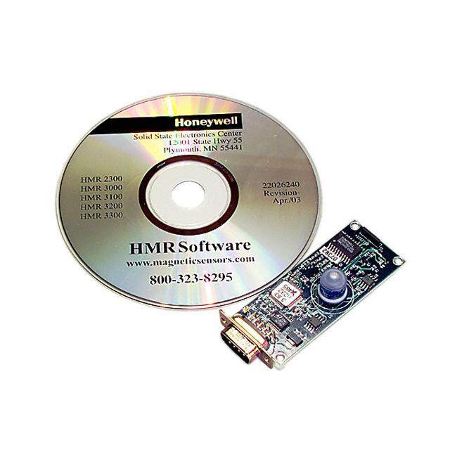
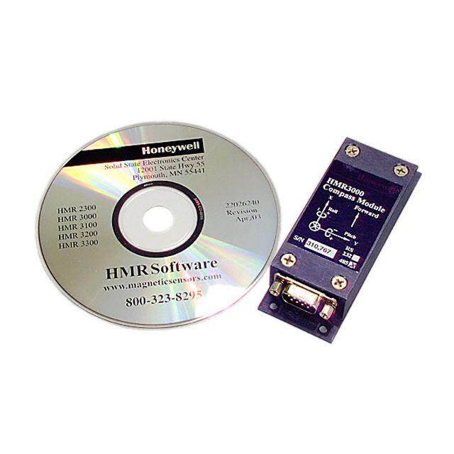
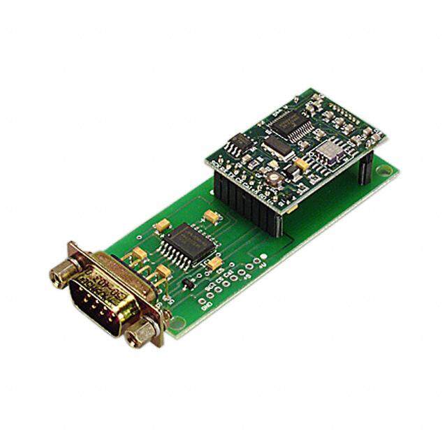
HMR3200/3300 COMPASS DEMONSTRATION KIT The HMR3200 or HMR3300 Demo kit includes additional hardware and Windows software to form a development kit for electronic compassing. This kit includes the HMR3200 orHMR3300 Printed Circuit Board (PCB) module as a daughter board, a TTL to RS-232 motherboard with a D9 serial port connector, 6’ serial port cable with attached AC adapter power supply, and a Windows demo software CD with documentation. The cable is a 4-wire design with pins 2 and 3 NOT flipped (DTE to DCE, not null modem) with pin 5 as the ground reference. Pin 9 is the unregulated positive voltage reference and is factory connected to the AC adapter. Either cable side may be used for the compass demo kit or computer serial port. The AC adapter is a universal type and factory set for 120 VAC input, 9 volt DC output, and positive polarity. Users can rewire the cable for battery operation for remote usage. Batteries chosen must apply the required 6 to 15 volt supply range with at least 24mA current capability. If compact 9 volt batteries are used, it is recommended that two batteries of the same chemistry be wired in parallel to have reasonable operational life. The TTL to RS-232 motherboard is designed to handle only unregulated power supply voltages and routes the supply directly to the V+ pin of the HMR3200 or HMR3300 daughterboard. The electronics on the motherboard convert the RX and TX 5 volt logic to the ±6 volt RS-232 drive logic for computer serial ports. ORDERING INFORMATION Ordering Number Product HMR3200 PCB Module Only HMR3200-Demo-232 PCB Module with Development Kit HMR3300 PCB Module Only HMR3300-D00-232 PCB Module and RS-232 Motherboard HMR3300-Demo-232 PCB Module with Development Kit Find out more For more information on Honeywell’s Magnetic Sensors visit us online at www.magneticsensors.com or contact us at 800-323-8295 (763-954-2474 internationally). The application circuits herein constitute typical usage and interface of Honeywell product. Honeywell does not warranty or assume liability of customer- designed circuits derived from this description or depiction. Honeywell reserves the right to make changes to improve reliability, function or design. Honeywell does not assume any liability arising out of the application or use of any product or circuit described herein; neither does it convey any license under its patent rights nor the rights of others. U.S. Patents 4,441,072, 4,533,872, 4,569,742, 4,681,812, 4,847,584 and 6,529,114 apply to the technology described Honeywell 12001 Highway 55 Plymouth, MN 55441 Form #900266 Rev F Tel: 800-323-8295 December 2005 wwwwww.h.hoonenyewyewlle.cllo.cmo/mma g n e ti c s e n s o r s © 2 0 0 5 H o n e y w e l l I n t e r n a t i o n a l I n c . 11