ICGOO在线商城 > 传感器,变送器 > 磁性传感器 - 罗盘,磁场(模块) > HMR3000-D00-485
 Datasheet下载
- 型号: HMR3000-D00-485
- 制造商: Honeywell Solid State Electronics
- 库位|库存: xxxx|xxxx
- 要求:
| 数量阶梯 | 香港交货 | 国内含税 |
| +xxxx | $xxxx | ¥xxxx |
查看当月历史价格
查看今年历史价格
HMR3000-D00-485产品简介:
ICGOO电子元器件商城为您提供HMR3000-D00-485由Honeywell Solid State Electronics设计生产,在icgoo商城现货销售,并且可以通过原厂、代理商等渠道进行代购。 HMR3000-D00-485价格参考。Honeywell Solid State ElectronicsHMR3000-D00-485封装/规格:磁性传感器 - 罗盘,磁场(模块), ±1 Gauss, ±40° Compass X, Y, Z 1 µGauss, 0.1° Module (No Case)。您可以下载HMR3000-D00-485参考资料、Datasheet数据手册功能说明书,资料中有HMR3000-D00-485 详细功能的应用电路图电压和使用方法及教程。
Honeywell Aerospace的HMR3000-D00-485是一款高性能磁性传感器模块,属于磁性传感器 - 罗盘类别,广泛应用于需要高精度磁场测量和方向定位的场景。以下是其主要应用场景:

 1. 航空航天与导航
   - HMR3000-D00-485专为航空航天领域设计,可提供精确的航向、姿态和位置信息。
   - 应用于飞机、无人机(UAV)和其他飞行器的惯性导航系统(INS),结合GPS实现精准定位。
   - 在卫星通信天线对准中,用于实时调整天线方向以确保信号质量。

 2. 海洋与船舶导航
   - 用于船舶和潜艇的电子罗盘系统,提供可靠的航向和偏航角度测量。
   - 支持水下机器人(ROV)和自主水下航行器(AUV)的方向控制和路径规划。

 3. 工业自动化
   - 在工业机器人中,用于监测机械臂的姿态和方向,确保精确运动控制。
   - 应用于旋转设备的角度测量和校准,例如风力发电机叶片方向调整。

 4. 地质勘探与矿产检测
   - 用于地球物理勘探,测量地磁场变化以识别地下矿藏或地质结构。
   - 支持管道检测设备(如爬行器)的方向跟踪和定位。

 5. 汽车与自动驾驶
   - 在自动驾驶车辆中,作为惯性导航系统的组成部分,提供车辆航向和偏移数据。
   - 用于电动助力转向系统(EPS)中的角度传感器,确保转向精确性。

 6. 医疗设备
   - 在医疗成像设备(如MRI)中,用于磁场校准和患者定位。
   - 支持手术机器人中的姿态感知功能,提升操作精度。

 7. 科学研究
   - 用于研究地球磁场的变化及其对环境和生物的影响。
   - 在空间科学实验中,监测宇宙射线和磁场干扰。

HMR3000-D00-485以其高灵敏度、低噪声和抗干扰能力著称,适用于需要在复杂电磁环境中工作的场景。同时,其RS-485通信接口便于集成到各种控制系统中,进一步拓展了其应用范围。
| 参数 | 数值 |
| 产品目录 | |
| 描述 | MODULE DIGITAL COMPASS RS485 |
| 产品分类 | |
| 品牌 | Honeywell Microelectronics & Precision Sensors |
| 数据手册 | |
| 产品图片 |
|
| 产品型号 | HMR3000-D00-485 |
| rohs | 不符合限制有害物质指令(RoHS)规范要求 |
| 产品系列 | HMR |
| 产品培训模块 | http://www.digikey.cn/PTM/IndividualPTM.page?site=cn&lang=zhs&ptm=4082http://www.digikey.cn/PTM/IndividualPTM.page?site=cn&lang=zhs&ptm=26237http://www.digikey.cn/PTM/IndividualPTM.page?site=cn&lang=zhs&ptm=30104 |
| 产品目录页面 | |
| 其它名称 | 342-1026 |
| 分辨率 | 1 µ高斯, 0.1° |
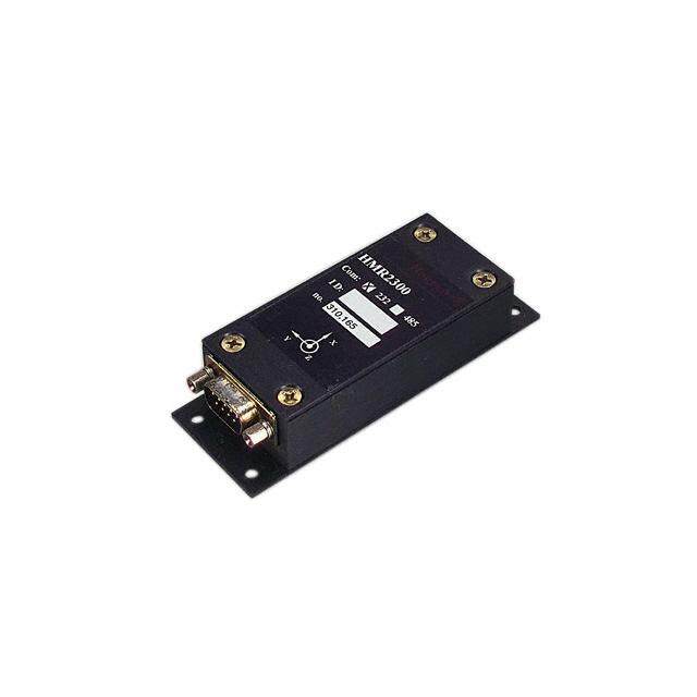
| 封装/外壳 | 模块(无外壳) |
| 接口 | RS-485 |
| 标准包装 | 1 |
| 测量范围 | ±1 高斯, ±40° |
| 特色产品 | http://www.digikey.cn/product-highlights/cn/zh/honeywell-micro-digital-compassing-solutions/3663 |
| 用于测量 | 制导,间距和卷 |
| 类型 | 数字罗盘 |
| 轴 | X,Y,Z |
| 配用 | /product-detail/zh/HMR3000-232-DEMO/342-1022-ND/334177 |


- 商务部:美国ITC正式对集成电路等产品启动337调查
- 曝三星4nm工艺存在良率问题 高通将骁龙8 Gen1或转产台积电
- 太阳诱电将投资9.5亿元在常州建新厂生产MLCC 预计2023年完工
- 英特尔发布欧洲新工厂建设计划 深化IDM 2.0 战略
- 台积电先进制程称霸业界 有大客户加持明年业绩稳了
- 达到5530亿美元!SIA预计今年全球半导体销售额将创下新高
- 英特尔拟将自动驾驶子公司Mobileye上市 估值或超500亿美元
- 三星加码芯片和SET,合并消费电子和移动部门,撤换高东真等 CEO
- 三星电子宣布重大人事变动 还合并消费电子和移动部门
- 海关总署:前11个月进口集成电路产品价值2.52万亿元 增长14.8%
PDF Datasheet 数据手册内容提取
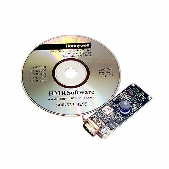
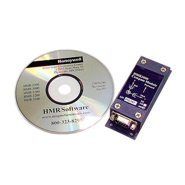
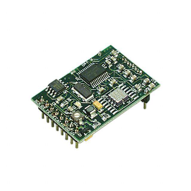
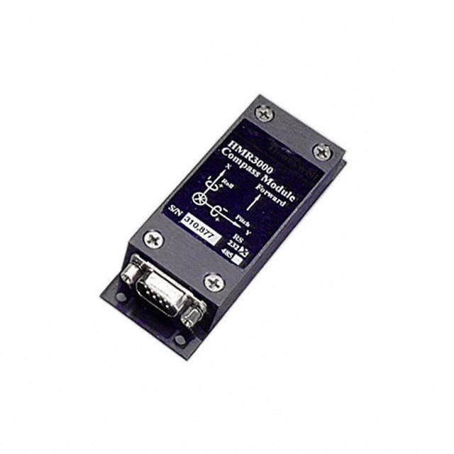
Digital Compass Solution HMR3000 The Honeywell HMR3000 is a digital compass module that provides heading, pitch, and roll outputs for navigation. The three of Honeywell’s magneto-resistive sensors are oriented in orthogonal directions plus a fluid tilt sensor are employed to measure the vector components of the earth’s magnetic field and a gravitational reference. These solid-state sensors create a strapdown compass that is both rugged and reliable. The data output is serial full-duplex RS-232 or half-duplex RS-485 with 1200 to 19,200 data rates. Applications include: Compassing & Navigation, Dead Reckoning Backup to GPS Systems, Marine Navigation, Antenna Positioning, and Land Surveying A RS-232 development kit version is available that includes a windows compatible demo program, interface cable, AC adapter, and carrying case. Honeywell continues to maintain product excellence and performance by introducing innovative solid-state magnetic sensor solutions. These are highly reliable, top performance products that are delivered when promised. Honeywell’s magnetic sensor solutions provide real solutions you can count on. FEATURES & BENEFITS BLOCK DIAGRAM 4 High Accuracy, <0.5° with 0.1° Resolution VV++ 4 Wide Tilt Range of ±40° GGnndd PPwwrr CCoonndd 4 Up to 20 Updates per Second µµCC TTXX 4 NMEA Standard Sentence Outputs AADDCC TT 4 Hard Iron Calibration Routine ARAR UU HHMMCC11000022 RRXX 4 RS-232 or RS-485 Serial Data Interfaces 4 PCB or Aluminum Enclosure Options 4 6 -15 volt DC Unregulated Power Supply HHMMCC11000011 22--TTAAIILLXXTTIISS EEEEPPRROOMM Interface
HMR3000 SPECIFICATIONS Characteristics Conditions Min Typ Max Units Power Supply Supply Voltage Pin 9 referenced to Pin 5 (Ground) +6.0 +15 Volts Pin 8 referenced to Pin 5 (Ground) +4.75 +5.0 +5.25 Supply Current Vsupply = +6V (Pin 9) mA Normal Operation 35 STOP Mode 13 SLEEP Mode 2.0 Temperature Operating Ambient -20 +70 °C Storage Ambient, Unpowered -35 100 °C Heading Accuracy Dip < 50°, Tilt < 20° 0.5 (1) °RMS Dip < 75°, Tilt < 20° 1.5 Resolution 0.1 degrees Repeatability ±0.3 degrees Magnetic Field Dynamic Range Adjustable ±1.0 gauss Resolution ±0.5 gauss range 1.0 milli-gauss Tilt Range Pitch, Roll ±40 degrees Accuracy (2) Tilt < 20° ±0.4 degrees Tilt >= 20° ±0.6 Repeatability ±0.2 degrees Resolution 0.1 degrees Interface Format RS-232 Full Duplex or RS-485 Half Duplex Baud Rate Full or Half Duplex 1200 19,200 bps Update Rate Continuous, per NMEA Sentence 1 20 Hz Mechanical Weight PCB Only 22 grams PCB and Flanged Enclosure 92 Shock MIL-STD-810E; TM 516.4 drop test 30 inches Vibration 20 to 2000Hz, Random for 2 Hours/axis MIL-STD-810E; TM514.4 *Notes: (1) Calculated values. (2) Device tilt not to exceed 75 degrees, or temporary loss of accuracy occurs. 2 www.honeywell.com
HMR3000 PIN CONFIGURATION Pin Number Pin Name Description 1 OP/CAL Operate/Calibrate (open = operate) 2 TD Transmit Data, RS-485 (B+) 3 RD Receive Data, RS-485 (A-) 4 RDY/SLP Ready/Sleep Input (open = ready) 5 GND Power and Signal Ground 6 RN/STP Run/Stop Input (open = run) 7 CT/RST Continue/Reset (open = continue) 8 +5V Regulated Power Input (+5 volts) 9 V+ Unregulated Power Input (+6 to +15 VDC) Pin assignments for 9-pin “D” connector. Power input shall be either regulated +5VDC (pin 8) or unregulated +6 to +15VDC (pin 9). Only one of the two pins shall be connected in a given installation to prevent HMR3000 damage. RS-232 UNBALANCED I/O INTERCONNECTS HHOOSSTT PPCC HHMMRR33000000 TTDD RRDD DD RR RRDD TTDD RR DD GGDD GGDD RS-485 BALANCED I/O INTERCONNECTS HHOOSSTT PPCC HHMMRR33000000 AA-- DD RRDD((AA)) RR TTDD((BB)) RR DD BB++ DATA COMMUNICATIONS The HMR3000 serial communications are governed by a simple asynchronous, ASCII protocol modeled after the NMEA 0183 standard. Either an RS-232 or an RS-485 electrical interface can be ordered. ASCII characters are transmitted and received using 1 start bit, 8 data bits (LSB first), no parity (MSB always 0), and 1 stop bit; 10 bits total per character. The baud rate defaults to 19,200 and can be reconfigured to 1200, 2400, 4800, 9600, 19200, 38400 bits per second. The www.honeywell.com 3
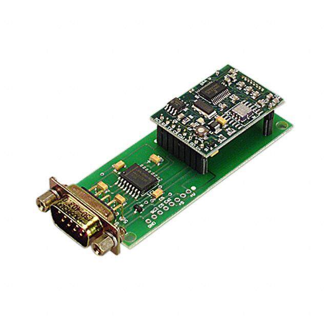
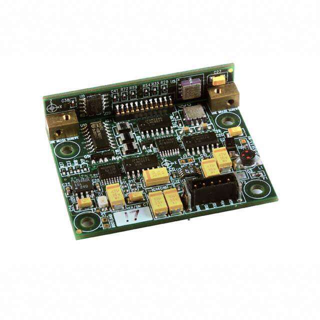
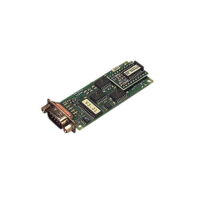
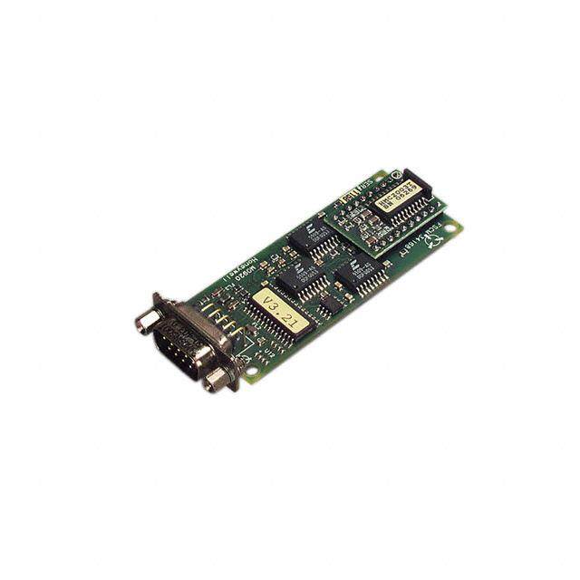
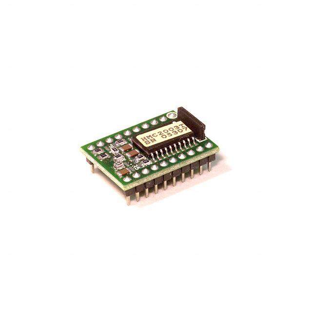
HMR3000 HMR3000 supports both standard NMEA 0183 and proprietary messages. Unsolicited NMEA messages are sent by the HMR3000 in Continuous Mode at the rates programmed in the EEPROM. HMR3000 also responds to all input messages from the host. An HMR3000 response to a command input may be delayed due to transmission of an unsolicited output. The host computer must wait for HMR3000 to respond to the last command input before sending another command message. All communication from and to HMR3000 contain a two-character Checksum Field at the end of the data fields, and are denoted in the sentences by ‘hh’. The checksum assures the accuracy of the message transmitted. This checksum is also calculated per NMEA 0183 Standard. The RS-232 signals are single-ended undirectional levels that are sent received simultaneously (full duplex). One signal is from the host personal computer (PC) transmit (TD) to the HMR3000 receive (RD) data line, and the other is from the HMR3000 TD to the PC RD data line. When a logic one is sent, either the TD or RD line will drive to about +6 Volts referenced to ground. For a logic zero, the TD or RD line will drive to about –6 Volts below ground. Since the signals are transmitted and dependent on an absolute voltage level, this limits the distance of transmission due to line noise and signal to about 60 feet. When using RS-485, the signals are balanced differential transmissions sharing the same lines (half-duplex). This means that logic one the transmitting end will drive the B line at least 1.5 Volts higher than the A line. For a logic zero, the transmitting end will drive the B line at least 1.5 Volts lower than the A line. Since the signals are transmitted as difference voltage level, these signals can withstand high noise environments or over very long distances where line loss may be a problem; up to 4000 feet. Note that long RS-485 lines should be terminated at both ends with 120-ohm resistors. Specific measurement descriptions and interface commands are not included in this datasheet but are included in the companion HMR3000 User’s Guide document. CIRCUIT DESCRIPTION The HMR3000 Digital Compass Module contains all the basic sensors and electronics to provide digital indication of heading and tilt. The HMR3000 has all three axis of magnetic sensors on the far end of the printed circuit board, away from the connector interface. The HMR3000 uses the circuit board mounting holes or the enclosure surfaces as the reference mechanical directions. The complete HMR3000 PCB assembly consists of a mother board and the 9-pin D- connector. The HMR3000 circuit starts with the Honeywell HMC1001 1-Axis Magnetic Sensor and the HMC1002 2-Axis Magnetic Sensor elements to provide the X, Y, and Z axis magnetic sensing of the earth’s field. These sensor output voltages are then amplfied and converted to a digital representation. A microcontroller integrated circuit receives the digitized magnetic field values (readings) by periodically querying the Analog to Digital Converter (ADC) and performs the necessary offset value corrections provided by the EEPROM via the calibration routine. This microcontroller also performs the external serial data interface and other housekeeping functions. The onboard EEPROM integrated circuit also is employed to retain necessary setup variables for best performance. A liquid filled two-axis (pitch, roll) tilt sensor is also used to create tilt compensated heading data. This tilt sensor performs an electronic gimballing function and is normally mounted flat (PCB horizontal) for maximum tilt range. APPLICATIONS PRECAUTIONS Several precautions should be observed when using magnetic compasses in general: • The presence of ferrous materials, such as nickel, iron, steel, and cobalt near the magnetometer will create disturbances in the earth’s magnetic field that will distort the X, Y, and Z field measurements. • Perming effects on the HMR3000 circuit board need to be taken into account. If the HMR3000 is exposed to fields greater than 10 gauss, then it is recommended that the enclosure/circuit boards be degaussed for highest sensitivity and resolution. A possible result of perming is a high zero-field output indication that exceeds specification limits. Degaussing wands are readily available from local electronics tool suppliers and are inexpensive. Severe field offset values could result if not degaussed. NON-FERROUS MATERIALS Materials that do not affect surrounding magnetic fields are: copper, brass, gold, aluminum, some stainless steels, silver, tin, silicon, and most non-metals. 4 www.honeywell.com
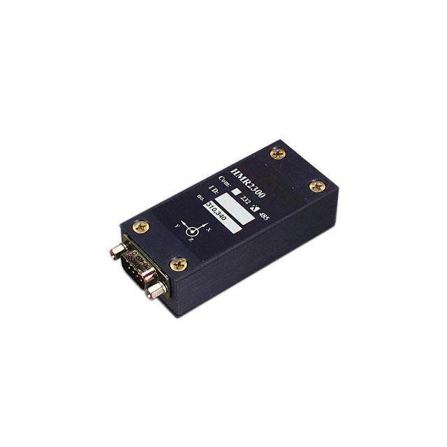
HMR3000 HANDLING PRECAUTIONS The HMR3000 Digital Compass Module measures fields within 1 gauss in magnitude. Computer floppy disks (diskettes) store data with field strengths of approximately 10 gauss. This means that the HMR3000 is many times more sensitive than common floppy disks. Please treat the compass with at least the same caution as your diskettes by avoiding motors, CRT video monitors, and magnets. Even though the loss of performance is recoverable, these magnetic sources will interfere with measurements. The fluidic tilt sensor works best when kept near level, and in calm to moderate vibration conditions. If turned upside down or violently jarred, not all the fluid will immediately return to the bottom of the tilt sensor’s glass ampoule. Accurate tilt and tilt compensated headings may be unavailable for a minute or two to allow for the fluid to transit to the bottom of the ampoule. PCB DIMENSIONS AND PINOUT CASE DIMENSIONS www.honeywell.com 5
HMR3000 DEMONSTRATION PCB MODULE KIT The HMR3000 Demonstration Kit includes additional hardware and Windows software to form a development kit for the digital compass module. This kit includes the HMR3000 PCB and enclosure, serial port cable with attached AC adapter power supply, and demo software plus documentation on a compact disk (CD). The figure below shows the schematic of the serial port cable with integral AC adapter. There will be three rotary switches on the AC adapter. These should be pointed towards the positive (+) polarity, +9 volts, and 120 or 240 VAC; depending your domestic supply of power. DD99--FF DD99--FF ddaattaa 22 22 33 33 ddaattaa 55 55 ggrroouunndd 99 99 ++99vvddcc GGRRYY BBLLKK AACC aaddaapptteerr ORDERING INFORMATION Ordering Number Product HMR3000-D00-232 PCB Only (No Enclosure), RS-232 I/O HMR3000-D00-485 PCB Only (No Enclosure), RS-485 I/O HMR3000-D21-232 Extended-Base Enclosure, RS-232 I/O HMR3000-D21-485 Extended-Base Enclosure, RS-485 I/O HMR3000-D21-232-DEMO Demo Kit, Extended-Base Enclosure, RS-232 I/O FIND OUT MORE For more information on Honeywell’s Magnetic Sensors visit us online at www.magneticsensors.com or contact us at 800-323-8295 (763-954-2474 internationally). The application circuits herein constitute typical usage and interface of Honeywell product. Honeywell does not warranty or assume liability of customer- designed circuits derived from this description or depiction. Honeywell reserves the right to make changes to improve reliability, function or design. Honeywell does not assume any liability arising out of the application or use of any product or circuit described herein; neither does it convey any license under its patent rights nor the rights of others. U.S. Patents 4,441,072, 4,533,872, 4,569,742, 4,681,812, 4,847,584 and 6,529,114 apply to the technology described Honeywell 12001 Highway 55 Plymouth, MN 55441 Form #900204 Rev D Tel: 800-323-8295 September 2006 6w w w . h o n e y w e l l . c o m / m a g n e t ic s e n s o r s © 2 0 0 6 H o n e y w e l l I n t e r n a t i o n a l I n c . www.honeywell.com