ICGOO在线商城 > 传感器,变送器 > 磁性传感器 - 线性,罗盘(IC) > HMC1022-TR
 Datasheet下载
- 型号: HMC1022-TR
- 制造商: Honeywell Solid State Electronics
- 库位|库存: xxxx|xxxx
- 要求:
| 数量阶梯 | 香港交货 | 国内含税 |
| +xxxx | $xxxx | ¥xxxx |
查看当月历史价格
查看今年历史价格
HMC1022-TR产品简介:
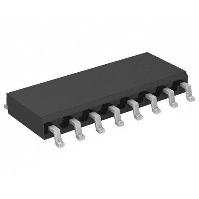
ICGOO电子元器件商城为您提供HMC1022-TR由Honeywell Solid State Electronics设计生产,在icgoo商城现货销售,并且可以通过原厂、代理商等渠道进行代购。 HMC1022-TR价格参考¥18.05-¥19.56。Honeywell Solid State ElectronicsHMC1022-TR封装/规格:磁性传感器 - 线性,罗盘(IC), Magnetoresistive Sensor X, Y Axis 16-SOIC。您可以下载HMC1022-TR参考资料、Datasheet数据手册功能说明书,资料中有HMC1022-TR 详细功能的应用电路图电压和使用方法及教程。
Honeywell Aerospace的HMC1022-TR是一款高性能的线性磁性传感器IC,广泛应用于需要精确测量地磁场和方向的场景。以下是其主要应用场景:

1. 导航系统:HMC1022-TR适用于各种导航设备,如手持式GPS设备、无人机导航系统以及自动驾驶车辆。它能够提供高精度的地磁场测量,帮助设备确定方向和位置。

2. 罗盘应用:作为一款罗盘IC,HMC1022-TR被广泛用于电子罗盘中,例如手机、平板电脑和其他便携式电子设备中的数字罗盘功能。它能够提供精确的方向信息,支持地图旋转和定位服务。

3. 工业自动化:在工业领域,该传感器可用于机器人定位、自动化设备的方向控制以及生产线上的物体检测。其高灵敏度和稳定性确保了工业应用中的精准操作。

4. 航空航天与国防:由于其卓越的性能和可靠性,HMC1022-TR也被应用于航空航天和国防领域,例如飞行器的姿态控制、导弹制导系统以及卫星定位系统中的方向感知模块。

5. 消费电子产品:在消费电子领域,这款传感器可用于游戏控制器、虚拟现实(VR)/增强现实(AR)设备等,提供更自然的人机交互体验。

6. 医疗设备:在医疗领域,HMC1022-TR可用于医疗器械中的方向监测,例如手术导航系统或可穿戴健康设备的位置追踪功能。

7. 汽车电子:在汽车行业中,该传感器可以用于电子稳定控制系统(ESC)、胎压监测系统(TPMS)以及电动车窗和座椅调节的方向检测。

总之,HMC1022-TR凭借其高精度、低功耗和良好的温度稳定性,成为众多需要精确磁场测量和方向感知的应用的理想选择。
| 参数 | 数值 |
| 产品目录 | |
| 描述 | SENSOR LINEAR MAGN 2 AXIS 16SOIC |
| 产品分类 | 磁性传感器 - 霍尔效应,数字开关,线性,罗盘 (IC) |
| 品牌 | Honeywell Microelectronics & Precision Sensors |
| 数据手册 | |
| 产品图片 |
|
| 产品型号 | HMC1022-TR |
| rohs | 无铅 / 符合限制有害物质指令(RoHS)规范要求 |
| 产品系列 | - |
| 产品培训模块 | http://www.digikey.cn/PTM/IndividualPTM.page?site=cn&lang=zhs&ptm=4082 |
| 产品目录页面 | |
| 供应商器件封装 | 16-SOIC |
| 其它名称 | 342-1005-1 |
| 包装 | 剪切带 (CT) |
| 封装/外壳 | 16-SOIC(0.154",3.90mm 宽) |
| 工作温度 | -55°C ~ 150°C |
| 感应范围 | ±6g |
| 标准包装 | 1 |
| 特性 | 罗盘 - 双轴 |
| 电压-电源 | 2 V ~ 25 V |
| 电流-电源 | 500mA |
| 电流-输出(最大值) | - |
| 类型 | 线性 |
| 输出类型 | 差分电压 |


- 商务部:美国ITC正式对集成电路等产品启动337调查
- 曝三星4nm工艺存在良率问题 高通将骁龙8 Gen1或转产台积电
- 太阳诱电将投资9.5亿元在常州建新厂生产MLCC 预计2023年完工
- 英特尔发布欧洲新工厂建设计划 深化IDM 2.0 战略
- 台积电先进制程称霸业界 有大客户加持明年业绩稳了
- 达到5530亿美元!SIA预计今年全球半导体销售额将创下新高
- 英特尔拟将自动驾驶子公司Mobileye上市 估值或超500亿美元
- 三星加码芯片和SET,合并消费电子和移动部门,撤换高东真等 CEO
- 三星电子宣布重大人事变动 还合并消费电子和移动部门
- 海关总署:前11个月进口集成电路产品价值2.52万亿元 增长14.8%


PDF Datasheet 数据手册内容提取
1- and 2-Axis Magnetic Sensors HMC1001/1002/1021/1022 The Honeywell HMC100x and HMC102x magnetic sensors are one and two-axis surface mount sensors designed for low field magnetic sensing. By adding supporting signal processing, cost effective magnetometers or compassing solutions are enabled. These small, low cost solutions are easy to assemble for high volume OEM designs. Applications for the HMC100x and HMC102x sensors include Compassing, Navigation Systems, Magnetometry, and Current Sensing. The HMC100x and HMC102x sensors utilize Honeywell’s Anisotropic Magnetoresistive (AMR) technology that provides advantages over coil based magnetic sensors. They are extremely sensitive, low field, solid-state magnetic sensors designed to measure direction and magnitude of Earth’s magnetic fields, from tens of micro-gauss to 6 gauss. Honeywell’s Magnetic Sensors are among the most sensitive and reliable low-field sensors in the industry. Honeywell continues to maintain product excellence and performance by introducing innovative solid-state magnetic sensor solutions. These are highly reliable, top performance products that are delivered when promised. Honeywell’s magnetic sensor solutions provide real solutions you can count on. FEATURES BENEFITS 4 Surface Mount 1 and 2-Axis Sensors 4Easy to Assemble & Compatible with High Speed SMT Assembly 4 Low Cost 4Designed for High Volume, Cost Effective OEM Designs 4 4-Element Wheatstone Bridges 4Low Noise Passive Element Design 4 Low Voltage Operations (2.0V) 4Compatible for Battery Powered Applications 4 Available in Tape & Reel Packaging 4High Volume OEM Assembly 4 Patented Offset and Set/Reset Straps 4Stray Magnetic Field Compensation 4 Wide Field Range (up to +/-6 Oe) 4Sensor Can Be Used in Strong Magnetic Field Environments
HMC1001/1002/1021/1022 HMC1001/1002 SPECIFICATIONS Characteristics Conditions* Min Typ Max Units Bridge Elements Supply Vbridge (Vb) referenced to GND - 5.0 12 Volts Resistance Bridge current = 10mA per bridge 600 850 1200 ohms Operating Temperature Ambient -55 150 °C Storage Temperature Ambient, unbiased -55 175 °C Field Range Full scale (FS) – total applied field -2 +2 gauss Linearity Error Best fit straight line ± 1 gauss 0.1 0.5 %FS ± 2 gauss 1.0 2.0 Hysteresis Error 3 sweeps across ±2 gauss 0.05 0.10 %FS Repeatability Error 3 sweeps across ±2 gauss 0.05 0.10 %FS S/R Repeatability Output variation after alternate S/R pulses Vb = 5V, ISR = 3A 100 m V Bridge Offset Offset = (OUT+) – (OUT-) -60 -15 +30 mV Field = 0 gauss after Set pulse, Vb = 8V Sensitivity Set/Reset Current = 3A 2.5 3.2 4.0 mV/V/gauss Noise Density @ 1Hz, Vb=5V 29 nV/sqrt Hz Resolution 10Hz Bandwidth, Vb=5V 27 m gauss Bandwidth Magnetic signal (lower limit = DC) 5 MHz Disturbing Field Sensitivity starts to degrade. 5 gauss Use S/R pulse to restore sensitivity. Sensitivity Tempco T = -40 to 125°C, Vb=8V -0.32 -0.30 -0.28 %/°C A T = -40 to 125°C, Ibridge=5mA -0.06 A Bridge Offset Tempco T = -40 to 125°C, No Set/Reset ±0.03 %/°C A T = -40 to 125°C, With Set/Reset ±0.001 A Bridge Ohmic Tempco T = -40 to 125°C 0.25 %/°C A Cross-Axis Effect Cross field = 1 gauss, Happlied = ±1 gauss ±3 %FS With set/reset ±0.5 Max. Exposed Field No perming effect on zero reading 10000 gauss Set/Reset Straps Resistance Measured from S/R+ to S/R- 1.5 1.8 ohms Current 0.1% duty cycle, or less, 2m sec current pulse 2.0 3.0 5 Amp Resistance Tempco T = -40 to 125°C 0.37 %/°C A Offset Straps Resistance Measured from OFF+ to OFF- 2.5 3.5 ohms Offset Constant DC Current 46 51 56 mA/gauss Field applied in sensitive direction Resistance Tempco T = -40 to 125°C 0.39 %/°C A * Tested at 25°C except stated otherwise. 2 www.honeywell.com
HMC1001/1002/1021/1022 HMC1021/1022 SPECIFICATIONS Characteristics Conditions* Min Typ Max Units Bridge Elements Supply Vbridge (Vb) referenced to GND 2 5.0 25 Volts Resistance Bridge current = 10mA per bridge 800 1100 1300 ohms Operating Temperature Ambient -55 150 °C Storage Temperature Ambient, unbiased -55 175 °C Field Range Full scale (FS) – total applied field -6 +6 gauss Linearity Error Best fit straight line ± 1 gauss 0.05 %FS ± 3 gauss 0.4 ± 6 gauss 1.6 Hysteresis Error 3 sweeps across ±2 gauss 0.08 %FS Repeatability Error 3 sweeps across ±2 gauss 0.08 %FS Bridge Offset Offset = (OUT+) – (OUT-) -10 ±2.5 +11.25 mV Field = 0 gauss after Set pulse, Vb = 5V Sensitivity Set/Reset Current = 0.5A 0.8 1.0 1.25 mV/V/gauss Noise Density @ 1Hz, Vb=5V 48 nV/sqrt Hz Resolution 10Hz Bandwidth, Vb=5V 85 m gauss Bandwidth Magnetic signal (lower limit = DC) 5 MHz Disturbing Field Sensitivity starts to degrade. 20 gauss Use S/R pulse to restore sensitivity. Sensitivity Tempco T = -40 to 125°C, Vb=5V -0.32 -0.30 -0.28 %/°C A T = -40 to 125°C, Ibridge=5mA -0.06 A Bridge Offset Tempco T = -40 to 125°C, No Set/Reset ±0.05 %/°C A T = -40 to 125°C, With Set/Reset ±0.001 A Bridge Ohmic Tempco T = -40 to 125°C 0.25 %/°C A Cross-Axis Effect Cross field = 1 gauss, Happlied = ±1 gauss +0.3 %FS Max. Exposed Field No perming effect on zero reading 10000 gauss Set/Reset Straps Resistance Measured from S/R+ to S/R- 5.5 7.7 9 ohms Current 0.1% duty cycle, or less, 2m sec current pulse 0.5 0.5 4.0 Amp Resistance Tempco T = -40 to 125°C 0.37 %/°C A Offset Straps Resistance Measured from OFF+ to OFF- 38 50 60 ohms Offset Constant DC Current 4.0 4.6 6.0 mA/gauss Field applied in sensitive direction Resistance Tempco T = -40 to 125°C 0.39 %/°C A * Tested at 25°C except stated otherwise. www.honeywell.com 3
HMC1001/1002/1021/1022 KEY PERFORMANCE DATA 4 www.honeywell.com
HMC1001/1002/1021/1022 PACKAGE / PINOUT SPECIFICATIONS Arrow indicates direction of applied field that generates a positive output voltage after a SET pulse. BASIC DEVICE OPERATION The Honeywell HMC100x and HMC102x Anisotropic Magneto-Resistive (AMR) sensors are simple resistive Wheatstone bridges to measure magnetic fields and only require a supply voltage for the measurement. With power supply applied to the bridges, the sensors convert any incident magnetic field in the sensitive axis directions to a differential voltage outputs. In addition to the bridge circuits, each sensor has two on-chip magnetically coupled straps; the offset strap and the set/reset strap. These straps are Honeywell patented features for incident field adjustment and magnetic domain alignment; and eliminate the need for external coils positioned around the sensors. The magnetoresistive sensors are made of a nickel-iron (Permalloy) thin-film deposited on a silicon wafer and patterned as a resistive strip element. In the presence of a magnetic field, a change in the bridge resistive elements causes a corresponding change in voltage across the bridge outputs. www.honeywell.com 5
HMC1001/1002/1021/1022 These resistive elements are aligned together to have a common sensitive axis (indicated by arrows on the pinouts) that will provide positive voltage change with magnetic fields increasing in the sensitive direction. Because the output only is in proportion to the one-dimensional axis (the principle of anisotropy) and its magnitude, additional sensor bridges placed at orthogonal directions permit accurate measurement of arbitrary field direction. The combination of sensor bridges in two and three orthogonal axis permit applications such as compassing and magnetometry. See Figure 1 for a representation of the magneto-resistive elements. OOuutt-- PPeerrmmaallllooyyTThhiinn FFiillmm VVbb GGnndd SSeennssiittiivvee EEaassyy AAxxiiss AAxxiiss OOuutt++ Figure 1 – Magneto-Resistive Wheatstone Bridge Elements The offset strap allows for several modes of operation when a direct current is driven through it. These modes are: 1) Subtraction (bucking) of an unwanted external magnetic field, 2) null-ing of the bridge offset voltage, 3) Closed loop field cancellation, and 4) Auto-calibration of bridge gain. The set/reset strap can be pulsed with high currents for the following benefits: 1) Enable the sensor to perform high sensitivity measurements, 2) Flip the polarity of the bridge output voltage, and 3) Periodically used to improve linearity, lower cross-axis effects, and temperature effects. Offset Straps The offset strap is a spiral of metallization that couples to the sensor element’s sensitive axis. The offset strap has some modest resistance and requires a moderate current flow for each gauss of induced field. The straps will easily handle currents to buck or boost fields through the linear measurement range, but designers should note the extreme thermal heating on the die when doing so. With most applications, the offset strap is not utilized and can be ignored. Designers can leave one or both strap connections (Off- and Off+) open circuited. Set/Reset Straps The set/reset strap is another spiral of metallization that couples to the sensor element’s easy axis (perpendicular to the sensitive axis on the sensor die). Each set/reset strap has a low resistance with a short but high required peak current for reset or set pulses. With rare exception, the set/reset strap must be used to periodically condition the magnetic domains of the magneto-resistive elements for best and reliable performance. A set pulse is defined as a positive pulse current entering the S/R+ strap connection. The successful result would be the sensor aligned in a forward easy-axis direction so that the sensor bridge’s polarity is a positive slope with positive fields on the sensitive axis result in positive voltages across the bridge output connections. A reset pulse is defined as a negative pulse current entering the S/R+ strap connection. The successful result would be the sensor aligned in a reverse easy-axis direction so that sensor bridge’s polarity is a negative slope with positive fields on the sensitive axis result in negative voltages across the bridge output connections. Typically a reset pulse is sent first, followed by a set pulse a few milliseconds later. By shoving the magnetic domains in completely opposite directions, any prior magnetic disturbances are likely to be completely erased by the duet of pulses. 6 www.honeywell.com
HMC1001/1002/1021/1022 For simpler circuits with less critical requirements for noise and accuracy, a single polarity pulse circuit may be employed periodically (all sets or all resets). With these uni-polar pulses, several uni-polar pulses become close in performance to a single bipolar set/reset pulse circuit. NOISE CHARACTERISTICS The noise density curve for a typical AMR sensor is shown in the figure below. The 1/f slope has a nominal corner frequency near 10Hz and flattens out to a 3.8 nV/sqrtHz slope. This is approximately equivalent to the Johnson noise (or white noise) for an 850 ohm resistor, the typical bridge resistance. To relate the noise density voltage to the magnetic fields, use the following expressions: For Vbridge = 5V and Sensitivity = 3.2mV/V/gauss, the bridge output (Voutput) is 16mV/gauss The noise density at 1Hz is about 30nV/sqrtHz or 1.8 micro-gauss/sqrtHz 1/f noise (0.1 to 10Hz) = 30 * sqrt[(ln10/0.1)] nV = 64nV (rms) = 4 micro-gauss (rms) = 27 micro-gauss (pk-pk) White noise (BW = 1kHz) = 3.8 * sqrt[BW] nV = 120nV (rms) = 50 micro-gauss (pk-pk) www.honeywell.com 7
HMC1001/1002/1021/1022 SET/RESET STRAP OPERATION The reasons to perform a set or reset on an AMR sensor are: 1) To recover from a strong external magnetic field that likely has re-magnetized the sensor, 2) to optimize the magnetic domains for most sensitive performance, and 3) to flip the domains for extraction of bridge offset under changing temperature conditions. Strong external magnetic fields that exceed a 10 to 20 gauss “disturbing field” limit, can come from a variety of sources. The most common types of strong field sources come from permanent magnets such as speaker magnets, nearby high- current conductors such as welding cables and power feeder cables, and by magnetic coils in electronic equipment such as CRT monitors and power transformers. Magnets exhibit pole face strengths in hundreds to thousands of gauss. These high intensity magnetic field sources do not permanently damage the sensor elements, but the elements will be disturbed to the exposed fields rather than the required easy axis directions. The result of this re-magnetization of the sensor elements, the sensor will lack sensitivity or indicate a “stuck” sensor output. Using the set and reset pulses will magnetically “restore” the sensor. AMR sensors are also ferromagnetic devices with a crystalline structure. This same thin film structure that makes the sensor sensitive to external magnetic fields also has the downside that changing magnetic field directions and thermal energy over time will increase the self-noise of the sensor elements. This noise, while very small, does impair the accurate measurement of sub-milligauss field strengths or changes in field strength in microgauss increments. By employing frequent set and reset fields on the sensor, the self-noise will be to its lowest possible level. As the sensor element temperature changes, either due to self-heating or external environments, each element’s resistance will change in proportion to the temperature. One way to eliminate the bridge offset voltage is to make stable magnetic field measurements of the bridge output voltage in between each set and reset field application. Since the external field components of the bridge output voltage will flip polarity, the set and reset bridge output voltages can be subtracted and the result divided by two to calculate the bridge offset. See application note AN212 for the details on bridge offset voltage computation and correction. SET/RESET DRIVE CIRCUITS The above description explained that providing pulses of electrical current creates the needed magnetic fields to realign the magnetic domains of the sensor resistive elements. Also the rationale for performing these set and reset pulses has been justified. The following paragraphs shall show when and how to apply these pulsed currents, and circuits to implement them. Figure 2 shows a simplistic schematic of a set/reset circuit. These set and reset pulses are shown in Figure 2 as dampened exponential pulse waveforms because the most popular method of generating these relatively high current, short duration pulses is via a capacitive “charge and dump” type of circuit. Most electronics, especially in consumer battery powered devices, do not have the capability to supply these high current pulses from their existing power supply sources. Thus “Vsr” is actually a charged up capacitor that is suddenly switched across the set/reset strap. The value of this capacitor is usually a couple hundred nano-Farads (h F) to a few micro-Farads (m F) depending on the strap resistance to be driven. The decay of the exponential waveform will mostly be governed by a time constant (t or Tau) that is the capacitance in farads multiplied by the resistance, and is measured in seconds. tt== RR**CC == ~~22mmsseecc IIsseett 11 IIrreesseett SS//RR++ VVssrr RRssrr 55 SSttrraapp SSeett//RReesseett RReessiissttaannccee PPuullssee SSoouurrccee SS//RR-- Figure 2 – A Simple Set/Reset Circuit 8 www.honeywell.com
HMC1001/1002/1021/1022 The next circuit implementation is the classic set/reset design in which a push-pull output stage (totem pole stage) drives one end of the HMC1001 set/reset strap, with the other end grounded. Figure 3 shows this circuit. RR11 VVDDDD 220000 88 VVoollttss CC11 1100UU RR22 2222KK XX11 IIRRFF77110055PP CC22 00..4477UU VVssrr CC44 00..11UU RRssrr RRssoouurrccee CC33 11..55 1100 XX22 00..4477UU VVssoouurrccee IIRRFF77110055NN Figure 3 – Totem Pole Set/Reset Circuit for HMC1001 The totem pole moniker comes from the stacked semiconductors between the positive supply voltage (VDD) and the negative connection (Ground). In the above example circuit, the semiconductors depicted are two complementary power MOSFETs, with the P-channel device on top and the N-channel device on the bottom. The International Rectifier IRF7105 part is chosen in this circuit as it contains both P-channel and N-channel MOSFET die in a very small package, and has the electrical characteristics needed for this circuit. Other manufacturers can be used as well with the requirements that they can be fully turned on/off with a 5-volt logic stimulus, handle the peak set/reset strap load currents, and present an “on” resistance at those peak currents that is fairly small in comparison to the connected strap load resistance. HIGHER VOLTAGE TOTEM POLE CIRCUITS While the previous example uses the convenience of standard 5-volt logic drive and modest supplies, many sensor designs require higher applied voltages to the set/reset straps to achieve greater currents or because the straps are series connected to assure even current distribution across all the straps pulsed. By creating series chains of straps, variances in strap resistance are less likely to fall out of the minimum or maximum range for peak pulse currents. If the straps are parallel connected, wide set/reset strap ohmic tolerances may be prone to “current hogging” and the straps will provide dissimilar magnetic fields at each sensor, potentially creating non-uniform accuracies at each sensor axis. The circuit in Figure 3 relies on MOSFETs that could predictably be turned off and on completely using logic level inputs. At higher voltages, the P-channel device needs its gate drive voltage to approach the source voltage, which is higher than usual logic levels. To perform this level shifting from logic levels to higher pulse source voltage supply levels, a BJT level shifter sub-circuit is employed to perform this task. Figure 4 shows this higher voltage operating circuit. From Figure 4, Rsr1, Rsr2, and Rsr3 are three strap resistances that are modeled from the HMC1001 or HMC1002 products. Three of these strap resistances are chosen since many users desire 3-axis magnetic field sensing that comes from a pairing of a HMC1001 and a HMC1002. Also this combination of three series straps is also used on the HMC2003 hybrid sensor module and in the HMR2300 Smart Digital Magnetometer. www.honeywell.com 9
HMC1001/1002/1021/1022 R5 220 10 C2 R1 10U Vdd 1000 Q1 3 2N2222 2 X1 1 IRF7105P Rsr1 Rsr2 1.8 1.8 Q2 2N2907 5 9 11 12 C1 C3 R2 0.22U Rsr3 1N 1000 1.8 4 R3 1000 Q3 7 6 2N2222 X2 Vset 8 IRF7105N D1 Vreset 1N4148 Figure 4 – Higher Voltage Set/Reset Circuit for HMC1001 & HMC1002 The three strap resistances are chosen at 1.8 ohms, or the worst-case high resistance points. Since they require a minimum of 3 amperes peak, the series combination requires at least 16.2 volts, so a circuit Vdd of about 18 volts would about the right level to drive the strap load and allocate for losses in the C1 capacitor ESR and the MOSFET switches X1 and X2. C1’s value is also chosen at 0.22 micro-farad so the circuit time constant is at least around 1 micro-second. Supply reservoir capacitor C2 is chosen to many times the value of C1 and is also picked for small size, working voltage, and low ESR relative to the strap load resistance. C2 typically will be in the 1 to 10 micro-farad range and best to error on the high capacitance side since C2 now supplies additional X1 gate drive circuitry. Resistor R5 is then chosen after C2 to set the recharge time constant and to limit peak supply current. These capacitors should be chosen to have a low ESR characteristic of around 0.2 ohms per capacitor. Working backwards from the strap load resistance, MOSFETs X1 and X2 are chosen as IRF7105 due to the total packaged size (both X1 and X2 in one SOIC-8), and meeting the requirements for operating voltages, peak currents, and low on resistances. X2 is directly driven from digital logic denoted as “Vset”, and “Vreset” drives the level shifting sub- circuit to X1. Note that Vreset turns off X2 first prior to X1 being driven on by Vset, and also X1 is turned off before X2 is turned on. While one logic line could control the operation of Vset and Vreset, the additional inverter stages and pulse delay components may be too space and cost consuming compared to two logic ports in a microcontroller. See Figure 4 in Application Note 201 for the discrete Vset and Vreset pulse forming circuit. Transistors Q1 and Q2 in Figure 4 are chosen to be generic BJTs to force MOSFET X1’s gate charge quickly into on and off states. Resistors R1 and R2 are selected as nominal 1000 ohm values that can pump or dump X1’s gate charge by supplying Q1 and Q2 with enough base drive currents to flip their on and off states. Transistor Q3 is also chosen as a generic, but reasonably fast switch transistor to perform the level shift function with resistors R1 and R2. Components R3, C3 and D1 are chosen to properly drive Q3 from a logic level source, with C3 and D1 denoted as a “speed-up” network to quickly switch Q3 within a few nanoseconds of logic transitions. 10 www.honeywell.com
HMC1001/1002/1021/1022 APPLICATION CIRCUITS The following are typical application circuits using the HMC100x and HMC102x sensors. TWO AXIS COMPASS OR MAGNETOMETER Figure 5 shows the typical schematic diagram. CC11 VVDDDD 11NN RR77 RR11 RR22 336600KK 885500 885500 RR55 VVDDDD 44..9999KK XX11AA 11 22 RR66 33 VVCCCC LLMMVV332244NN 44..9999KK VVEEEE 66 XXOOUUTT VVDDDD C0C0..3311UU 44 RR88 VVDDDD RR33 RR44 336600KK 885500 885500 XX11CC RR1199 LLMMVV332244NN VVRREEFF 11KK VVCCCC HHMMCC11000022 CC22 VVEEEE VVRREEFF VVDDDD 11NN 1155 RR1155 RR2200 RR99 RR1100 336600KK 11KK 885500 885500 RR1133 VVDDDD 44..9999KK XX11BB 88 99 RR1144 1111 VVCCCC LLMMVV332244NN YYOOUUTT 44..9999KK VVEEEE 1122 1100 RR1111 RR1122 R3R366110066KK C1C10044UU R1R100220011 885500 885500 1144 1133 VVSSRR XX22 VVRREEFF RR1177 CC55 IIRRFF77110055PP 1188 11..55 00..4477UU SSRR__IINN 1166 1177 RR1188 CC66 XX33 11..55 00..4477UU IIRRFF77110055NN Figure 5 – 2-Axis Compass or Magnetometer From Figure 5, the typical power supplied for VDD is nominally 5 volts, with about 8 volts for the set/reset strap supply (VSR). A pair of complementary power MOSFETs provides the electronic switch functions, driving the set/reset minus pins with the set/reset plus pins returned to the MOSFET ground. The MOSFETs are driven by typical 5 volt logic with normally high levels expected when not pulsing. Each logic transition creates a very high current pulse, as high-to-low transitions turn-on the P-channel FET while turning-off the N-channel FET. This transfers some of the energy from the 10uf reservoir capacitor to the pair of 0.47uf capacitors while providing a positive pulse. A negative pulse is performed on the low-to-high logic transition as the P-channel FET is turned off and the N-channel FET is turned on. Then the energy from the pair of 0.47uf capacitors is discharged through the set/reset straps and the N-channel MOSFET. Ceramic capacitors with a low-ESR characteristic are required for best pulse performance. Since the sensor output difference voltage is amplified by low cost operational amplifiers with a low supply voltage feature (LMV324N), the amplifier requires a half supply voltage reference (VREF). This reference voltage is formed via a buffered rail-splitter circuit, using a spare op-amp and resistors. The 1 nano-farad capacitors are used to bandwidth limit the sensor, and to suppress interference. The resistors around the op-amp are chosen for earth’s magnetic field strength (about 0.6 gauss) levels and to match with the sensor impedance. The 4.99k-ohm resistors are a bridging impedance that is normally chosen to be 4 to 10 times larger than the sensor bridge resistance elements (HMC1002) at 850 ohms. The www.honeywell.com 11
HMC1001/1002/1021/1022 360k-ohm feedback and reference resistors are chosen to provide a nominal 230mV/V/gauss gain characteristic or 1.15V/gauss gain with VDD at 5 volts. Other values than 360k-ohms may be chosen; with smaller resistances for larger fields and larger resistances for lower field strengths. Be aware that sensor bridge offsets factor into the signal gain selection as the offsets may be as large as the signal to be measured. See application note AN212 on methods to handle bridge offset voltages. As a magnetometer, the circuit outputs (Xout and Yout) should be measured against VREF and scaled for 1.15 volts per gauss using a 5 volt sensor/amplifier power supply (VDD). Since the sensor’s bandwidth is 5 MHz, the sampling rate of the outputs can be very fast, to the point were the filtering and speed of the amplifiers begins to effect the measurements. Resolution will be mostly to the size of the Analog-to-Digital Converter (ADC), where a 10-bit ADC would spread its 1024 counts across the power supply or tighter. As a compass, the two outputs constrain the earth’s magnetic field measurement to horizontal orientations with the Xout and Yout feeding the heading equation of arctan (Yout/Xout) in degrees. The Xout direction of the HMC1002 should be mounted to the forward direction of the product for proper orientation. If a tilt-compensated compass is desired, a third axis could be made from the spare LMV324N amplifier and a HMC1001 sensor. Refer to the technical papers on compassing from the website for more detail on compass implementation. Field Detector or Current Sensor A simple sensor implementation is shown in Figure 6 for a single axis sensor and signal conditioning circuitry for detecting a magnetic disturbance, or as a current sensor when placed near a current carrying conductor. For more details on current sensing, see application note AN209 on the website. From Figure 6, the HMC1021 sensors are different from the HMC100x parts in that the bridge resistances increase to 1100 ohms and the set/reset strap resistance increases to 4.5 ohms. Because the minimum set/reset peak current is down to 0.5 amperes, the set/reset drive circuit can now be run at common supply rails of 5 or 3 volts (VDD). Due to the increased resistance of the set/reset strap, capacitor C3 can be reduced to about 0.22uf to maintain the desired 1 to 2 microsecond time constant. Capacitor C2 is typically chosen to be about ten times the series capacitor value, or 2.2uf. The same pulse transition scheme in Figure 5 applies to Figure 6. The sensor/amplifier circuit is likewise similar but the 1mV/V/gauss sensitivity requires a gain boost by increasing feedback/reference resistors for sensing low fields like earth’s magnetic field. If a 2 or 3-axis compass is to be designed with the HMC102x series sensor, parts like the HMC1022 plus the HMC1021Z can be used, with replication of the difference amplifier stages for each axis. By choosing the 1 Meg-ohm and 4.99k-ohm resistors, the gain with a 5 volt supply produces about a 1V/gauss transfer characteristic and centered at half supply (2.5 volts). An instrumentation amplifier could be substituted for the operational amplifier to minimize external discrete components, but the very low cost of op-amps like the LMV741/LMV358/LMV324 family is hard to beat if price is more important than printed circuit board footprint. The signal output of the amplifier can be directly placed on the input of an ADC and further processed in digital form. If the ADC range spans the power supply range, then a 10-bit ADC can have count 512 of 1024 used as the zero gauss point when the output rests at half-supply. If 3 volt operation is required, the designer can substitute the IRF7507 part for the IRF7105 for 2.7 volt logic drive of the complementary MOSFET gates. 12 www.honeywell.com
HMC1001/1002/1021/1022 CC11 VVDDDD 11NN RR77 11MMEEGG RR11 RR22 11..11KK 11..11KK RR55 VVDDDD 44..9999KK XX11AA 11 22 LLMMVV332244NN RR66 33 VVCCCC XXOOUUTT 44..9999KK 66 VVEEEE 44 RR88 RR33 RR44 11MMEEGG 11..11KK 11..11KK 88 VVDDDD RR99 RR1100 1100KK 1100KK HHMMCC11002211 CC22 RR1111 22..22UU 220000 VVDDDD 1144 XX22 RR1122 CC33 IIRRFF77110055PP 1188 44..55 00..2222UU SSRR__IINN 1166 1177 XX33 IIRRFF77110055NN Figure 6 – Field Detector or Current Sensor MOUNTING CONSIDERATIONS Stencil Design and Solder Paste A 4 mil stencil and 100% paste coverage is recommended for the electrical contact pads. Pick and Place Placement is machine dependant and no restrictions are recommended. Reflow and Rework No special profile is required for the HMC10xx parts. The product is compatible with lead and no-lead eutectic solder paste reflow profiles. Honeywell recommends the adherence to solder paste manufacturer’s guidelines. The sensors may be reworked with soldering irons, but extreme care must be taken not to overheat the part’s circuit board pads. Irons with a tip temperature no greater than 315°C should be used. Excessive rework risks the copper pads pulling away into the molten solder. www.honeywell.com 13
HMC1001/1002/1021/1022 PACKAGE OUTLINES 14 www.honeywell.com
HMC1001/1002/1021/1022 ORDERING INFORMATION Ordering Number Product Packaging HMC1001 One Axis Magnetic Sensor, 8-pin SIP ESD Tubes HMC1002 ESD Tubes Two Axis Magnetic Sensor, 20-pin SOIC HMC1002-TR 1,000 Tape & Reel HMC1021S ESD Tubes One Axis Magnetic Sensor, 8-pin SOIC HMC1021S-TR 1,000 Tape & Reel HMC1021Z One Axis Magnetic Sensor, 8-pin SIP ESD Tubes HMC1022 Cut Tape Two Axis Magnetic Sensor, 16-pin SOIC HMC1022-TR 2,500 Tape & Reel * When ordering the –RC in the product part number represents RoHS compliant. This labeling is temporary during the transition period from leaded to non-leaded parts. FIND OUT MORE For more information on Honeywell’s Magnetic Sensors visit us online at www.magneticsensors.com or contact us at 800-323-8295 (763-954-2474 internationally). The application circuits herein constitute typical usage and interface of Honeywell product. Honeywell does not warranty or assume liability of customer- designed circuits derived from this description or depiction. Honeywell reserves the right to make changes to improve reliability, function or design. Honeywell does not assume any liability arising out of the application or use of any product or circuit described herein; neither does it convey any license under its patent rights nor the rights of others. U.S. Patents 4,441,072, 4,533,872, 4,569,742, 4,681,812, 4,847,584 6,529,114 and 7,095,226 apply to the technology described Honeywell 12001 Highway 55 Plymouth, MN 55441 Form #900248 Rev C Tel: 800-323-8295 August 2008 wwwwww.h.hoonneeywywelel.cllo.cmo/mm a g n e t i c s e n s o r s © 2 0 0 8 H o n e y w e l l I n te r n a t io n a l In c . 15