 Datasheet下载
- 型号: HFBR-2506AMZ
- 制造商: Avago Technologies
- 库位|库存: xxxx|xxxx
- 要求:
| 数量阶梯 | 香港交货 | 国内含税 |
| +xxxx | $xxxx | ¥xxxx |
查看当月历史价格
查看今年历史价格
HFBR-2506AMZ产品简介:
ICGOO电子元器件商城为您提供HFBR-2506AMZ由Avago Technologies设计生产,在icgoo商城现货销售,并且可以通过原厂、代理商等渠道进行代购。 HFBR-2506AMZ价格参考。Avago TechnologiesHFBR-2506AMZ封装/规格:光纤 - 接收器, Fiber Optic Receiver 通用 16MBd 4.75V ~ 5.25V 27mA。您可以下载HFBR-2506AMZ参考资料、Datasheet数据手册功能说明书,资料中有HFBR-2506AMZ 详细功能的应用电路图电压和使用方法及教程。
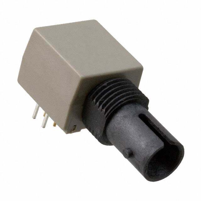
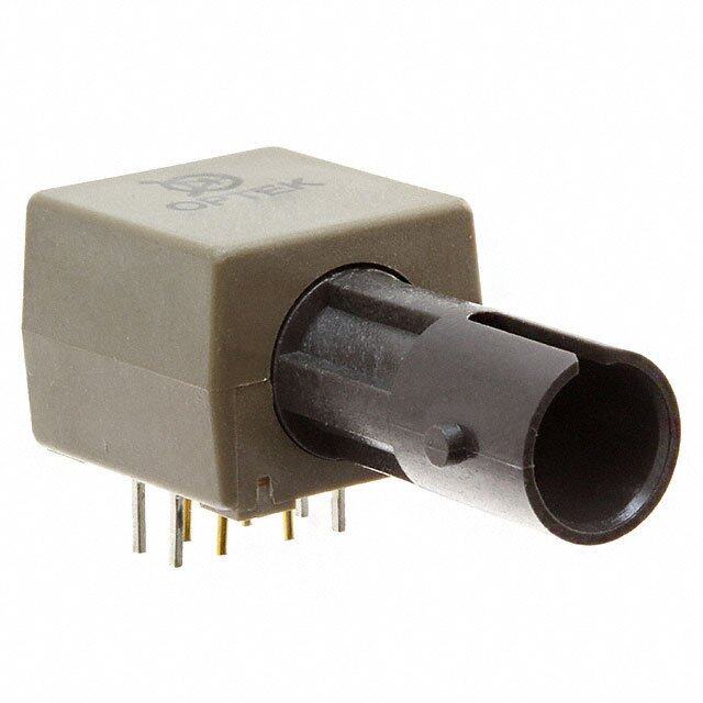
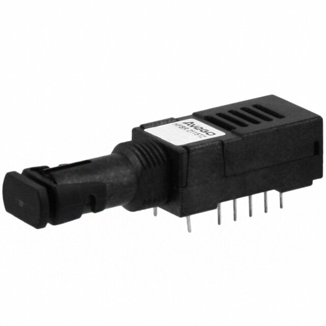
HFBR-2506AMZ是由Broadcom Limited(原惠普/安捷伦)生产的一款光纤接收器,属于其HFBR-25xx系列高速光通信产品。该器件主要应用于工业、通信和自动化领域中的短距离光纤数据传输系统。

典型应用场景包括工业自动化控制系统,如PLC(可编程逻辑控制器)之间的高速通信,用于抗电磁干扰要求高的工厂环境;在电信设备中,常用于局域网(LAN)、现场总线(如PROFIBUS、DeviceNet)等协议的光信号接收,实现电气隔离与信号完整性保障;此外,也广泛用于医疗设备、测试仪器及轨道交通控制系统中,以确保在高噪声环境下稳定可靠的数据接收。

HFBR-2506AMZ采用多模光纤接口,支持高达11MBd的数据速率,兼容TTL电平输出,便于与数字电路连接。其内置的光电探测器和放大电路具有良好的灵敏度和响应速度,工作温度范围宽,适合严苛工业环境使用。同时,该器件具备优异的电磁兼容性(EMC)和抗干扰能力,能有效隔离接地环路,提升系统稳定性。

综上,HFBR-2506AMZ是一款适用于工业通信、自动化控制、医疗与交通等领域的高性能光纤接收模块,特别适合需要高可靠性与电气隔离的短距离光通信应用。
| 参数 | 数值 |
| 产品目录 | |
| 描述 | RCVR OPTICAL 16MBD SERCOS SMA光纤发射器、接收器、收发器 SERCOS 16MBd SMA RX RoHS |
| 产品分类 | |
| 品牌 | Avago Technologies US Inc. |
| 产品手册 | http://www.avagotech.com/pages/en/optical_receivers/fieldbus_sercos_interface/hfbr-2506amz/ |
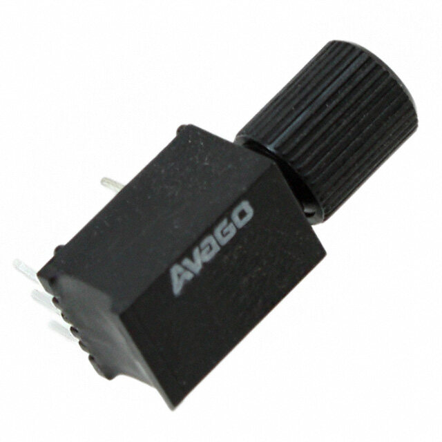
| 产品图片 |
|
| rohs | 符合RoHS无铅 / 符合限制有害物质指令(RoHS)规范要求 |
| 产品系列 | 光纤发射器、接收器、收发器,Avago Technologies HFBR-2506AMZ- |
| 数据手册 | http://www.avagotech.com/docs/AV02-1507EN |
| 产品型号 | HFBR-2506AMZ |
| 产品 | Transmitters |
| 产品种类 | 光纤发射器、接收器、收发器 |
| 其它名称 | 516-2775 |
| 功率-可接受的最小值 | - |
| 商标 | Avago Technologies |
| 封装 | Tube |
| 封装/箱体 | - |
| 工作电源电压 | 5 V |
| 工厂包装数量 | 100 |
| 应用 | 通用 |
| 数据速率 | 16MBd |
| 最大工作温度 | + 85 C |
| 最大输出电流 | 16 mA |
| 最小工作温度 | - 40 C |
| 标准包装 | 100 |
| 波长 | 650 nm |
| 电压-电源 | 4.75 V ~ 5.25 V |
| 电流-电源 | 27mA |
| 纤维类型 | Hard Clad Silica |


- 商务部:美国ITC正式对集成电路等产品启动337调查
- 曝三星4nm工艺存在良率问题 高通将骁龙8 Gen1或转产台积电
- 太阳诱电将投资9.5亿元在常州建新厂生产MLCC 预计2023年完工
- 英特尔发布欧洲新工厂建设计划 深化IDM 2.0 战略
- 台积电先进制程称霸业界 有大客户加持明年业绩稳了
- 达到5530亿美元!SIA预计今年全球半导体销售额将创下新高
- 英特尔拟将自动驾驶子公司Mobileye上市 估值或超500亿美元
- 三星加码芯片和SET,合并消费电子和移动部门,撤换高东真等 CEO
- 三星电子宣布重大人事变动 还合并消费电子和移动部门
- 海关总署:前11个月进口集成电路产品价值2.52万亿元 增长14.8%

.jpg)
PDF Datasheet 数据手册内容提取
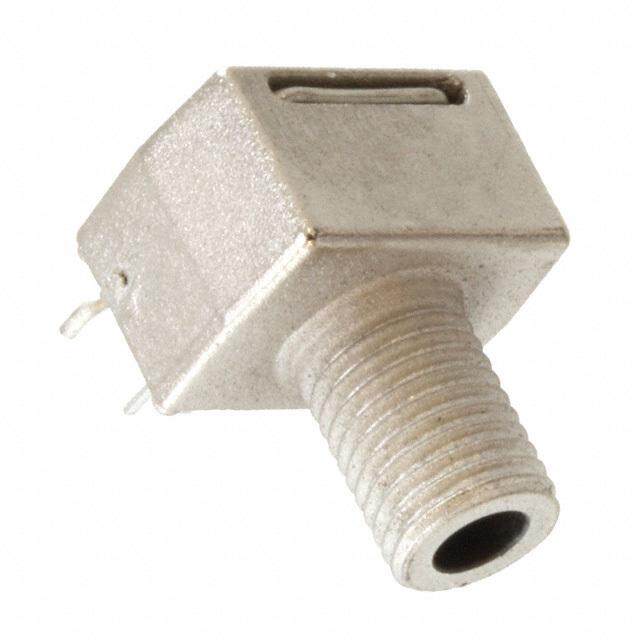
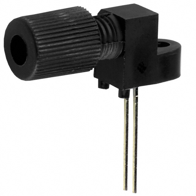
HFBR-1506AMZ/HFBR-2506AMZ Fiber Optic SMA Transmitters and Receivers for 16 MBd SERCOS Applications Data Sheet Description Features SERCOS, an acronym for SErial Realtime COmmunications RoHS-Compliant Systems, is a standard digital interface for communication Meets Industrial SERCOS 16MBd standard in industrial CNC applications. SERCOS is a European (EN SMA ports 61491) and international standard (IEC 61491). The opti- 650 nm wavelength cal interface allows data rates of 2,4,8 and 16 MBd and Metal coated, plastic packaging data transfer between numerical controls and drives via fi ber-optic rings, with voltage isolation and noise immu- Specifi ed for use with 1 mm POF and 200 μm HCS nity. The HFBR-1506AMZ and HFBR-2506AMZ products DC - 16 MBd data rate have a guaranteed performance up to 16 MBd. Applications Industrial Control Data Links Factory Automation Data Links Voltage Isolation Applications
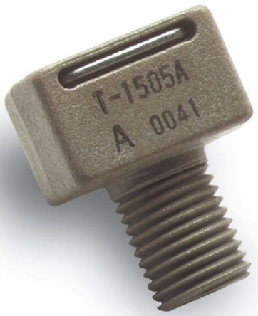
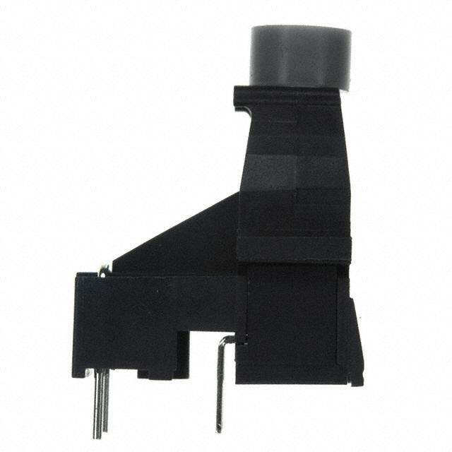
Package Information Recommended Chemicals for Cleaning/Degreasing The RoHS-compliant transmitters and receivers are Alcohols: methyl, isopropyl, isobutyl. housed in a low-cost, dual-in-line package that is made Aliphatics: hexane, heptane. of high strength, heat resistant, chemically resistant and UL 94V-O (UL fi le # E121562) fl ame retardant plastic. Other: soap solution, naphtha. Both the transmitter and receiver are coated with a layer Do not use partially halogenated hydrocarbons such as of conductive alloy for better air discharge (ESD) perfor- 1,1,1 trichloroethane, ketones such as MEK, acetone, mance. The package is designed for auto insertion and chloroform, ethyl acetate, methylene dichloride, phenol, wave soldering so it is ideal for high volume production methylene chloride or N-methylpyrolldone. Also, Avago applications. Technologies does not recommend the use of cleaners Handling and Design Information that use halogenated hydrocarbons because of their potential environmental harm. When soldering, it is advisable to leave the protective cap on the unit to keep the optics clean. Good system performance requires clean port optics and cable ferrules to avoid obstructing the optical path. Clean compressed air often is suffi cient to remove particles of dirt; methanol on a cotton swab also works well. CAUTION: The small junction size inherent in the design of these components increases the components’ susceptibility to damage from elec- trostatic discharge (ESD). It is advised that normal static precautions be taken in handling and assembly of these components to prevent damage and/or degradation which may be induced by ESD. Link Performance Specifi cation 0 °C to +70 °C unless otherwise noted. Parameter Symbol Min Max Unit Condition Reference Link distance with HFBR-1506AMZ/2506AMZ I 0.1 45 m POF Note 1, 2, 4, 6 0.1 200 m HCS Note 1, 3, 5, 6 Notes: 1. 60 mA nominal drive current. 2. POF HFBR-ExxyyyZ 0.23 dB/m worst case attenuation. 3. HCS 10 dB/km worst case attenuation. 4. Including a 3 dB optical safety margin accounting for link service lifetime. 5. Including a 2 dB optical safety margin accounting for link service lifetime. 6. Signaling rate dc to 16 MBd. 2
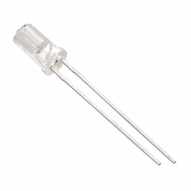
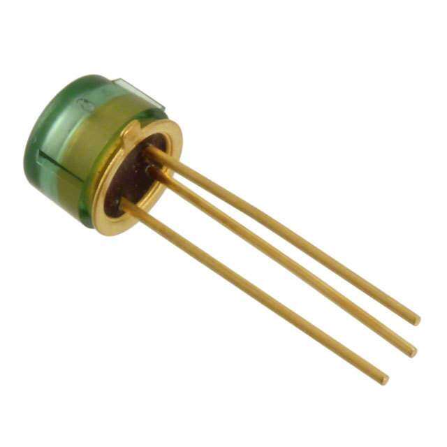
HFBR-1506AMZ Transmitter 4 5 PIN FUNCTION The HFBR-1506AMZ transmitter incoporates a 650nm 6 1 CONNECTED TO PIN 4 LED in a metal-coated, plastic housing. The high light 7 4 CONNECTED TO PIN 1 1 8 5 GND output power enables the use of both plastic optical 6 GND fi ber (POF) and Hard Clad Silica (HCS). This transmitter BOTTOM VIEW, 7 CATHODE can operate up to 16MBd using a simple driver circuit. HFBR-1506AMZ 8 ANODE The HFBR-1506AMZ is compatible with SMA connectors. SEE NOTE 6 Figure 1. Absolute Maximum Ratings Parameter Symbol Min Max Unit Notes Storage and Operating Temperature TS, O -40 +85 °C Peak Forward Input Current IF, PK 90 mA 1 Average Forward Input Current IF, AVG 60 mA Reverse Input Voltage VR 3 V Lead Soldering Cycle Temp TSOL 260 °C 2, 8 Time TSOL 10 s Electrical Characteristics Table 0 °C to +70 °C unless otherwise noted. Parameter Symbol Min Typ1 Max Unit Condition Notes Optical Power Temperature Coeffi cient PT/T -0.02 dB/°C Forward Voltage VF 1.8 2.1 2.65 V IF, dc = 60 mA Figure 2 Forward Voltage Temperature Coeffi cient VF/T -1.8 mV/°C Figure 2 Breakdown Voltage VBR 3.0 13 V IF, dc = -10 μA Peak Emission Wavelength lPK 640 650 660 nm Figure 4 Full Width Half Max FWHM 21 30 nm Figure 4 Diode Capacitance CO 60 pF VF = 0 V, f = 1 MHz Thermal Resistance qJC 140 °C/W Notes 4, 5 Rise Time (10% to 90%) tr 15 ns 10% to 90% Figure 6 Fall Time (90% to 10%) tf 15 ns IF = 60 mA Figure 6 Peak Output Power 0 °C to +70 °C unless otherwise noted. Model Number Symbol Min Max Unit Condition Reference HFBR-1506AMZ Pr -6.0 -2.0 dBm POF, IF, dc = 60 mA Note 7 -18.0 -10.0 HCS®, IF, dc = 60 mA Figure 3 Notes: 1. For I F_PK > 60 mA, the duty factor must maintain I F_AVG <= 60 mA and pulse width <= 1 μs. 2. 1.6 mm below seating plane. 3. Typical data are at +25 °C 4. Thermal resistance is measured with the transmitter coupled to a connector assembly and fi ber, and mounted on a printed circuit board. 5. To further reduce the thermal resistance, the cathode trace should be made as large as is consistent with good RF circuit design. 6. Pins 1 and 4 are for mounting and retaining purposes, but are electrically connected, pins 5 and 6 are electrically isolated. It is recommended that pins 1, 4, 5 and 6 all be connected to ground to reduce coupling of elecrical noise. 7. Optical power measured at the end of 1 meters of 1 mm diameter plastic or 200 μm hard/plastic clad silica optical fi ber with a large area detec- tor. 8. Moisture sensitivity level (MSL) is 3. 3
2.5 10 1.4 -40 ˚C -40 ˚C -40 ˚C 2.3 0 ˚C Bd – 0 25 ˚C REW 1.2 V – EGA 2.1 2750 ˚˚CC REWOP -10 OP TUP 1.0 0 ˚C25 ˚C TLOV DR 1.9 TUPTUO -20 85 ˚C TUO LAR 00..68 7805 ˚˚CC AWROF – VF 1.7 85 ˚C DEZILAMRON -30 TCEPS DEZILA 00..42 1.51 10 100 – PT -401 10 100 MRON 0610 630 650 670 690 IF,DO – TRANSMITTER DRIVE CURRENT – mA IF,DO – TRANSMITTER DRIVE CURRENT – mA WAVELENGTH – nm Figure 2. Typical Forward Voltage vs Drive Cur- Figure 3. Typical Normalized Optical Power vs Figure 4. Typical Normalized Optical Spectra rent Drive Current Figure 5. Recommended drive circuit according to SERCOS An17 (Ifnom ~ 35 mA) 4
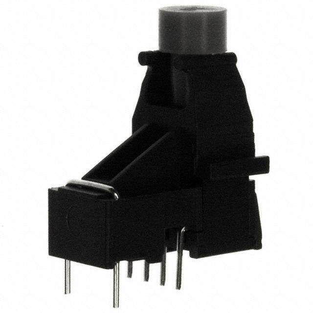
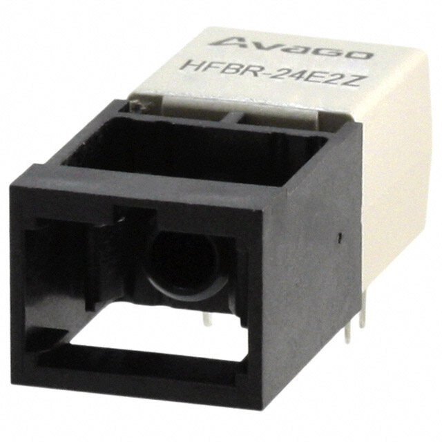
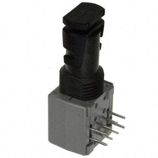
HFBR-2506AMZ Receiver PIN FUNCTION 4 5 The HFBR-2506AMZ receiver is housed in a metal-coated, 6 1 CONNECTED TO PIN 4 4 CONNECTED TO PIN 1 plastic package, consists of a silicon PIN photodiode and 7 5 NO CONNECT 1 8 digitizing IC to produce a logic compatible output. The 6 VCC 7 GND IC includes a unique circuit to correct the pulse width BOTTOM VIEW, 8 VO distortion of the fi rst bit after a long idle period. This HFBR-2506AMZ enables operation from DC to 16MBd with low PWD for SEE NOTE 4 arbitrary data patterns. Figure 6. The receiver is a “push-pull” stage compatible with TTL and CMOS logic. The HFBR-2506AMZ is compatible with SMA connectors. Absolute Maximum Ratings Parameter Symbol Min Max Unit Notes Storage and Operating Temperature TS, O -40 +85 °C Supply Voltage VCC -0.5 5.5 V Average Output Current IO, AVG 16 mA Output Power Dissipation POD 80 mW Lead Soldering Cycle Temp TSOL 260 °C 1, 5 Time TSOL 10 s Electrical Characteristics Table 0 °C to +70 °C °C, 4.75 V < V < 5.25 V, V Noise < = 100 mV unless otherwise noted. CC P-P Parameter Symbol Min Typ1 Max Unit Condition Notes Peak Input Power Level Logic HIGH PRH -42 dBm 1 mm POF -44 200 μm HCS Peak Input Power Level Logic LOW PRL -20 -2 dBm 1 mm POF 3 -22 -10 200 μm HCS |PWD| < 19 ns Supply Current ICC 27 45 mA VO = Open High Level Output Voltage VOH 4.2 4.7 V IO = 40 μA Low Level Output Voltage VOH 0.22 0.4 V IO = 1.6 mA Pulse Width Distortion PWD -19 19 ns Propagation Delay Time TP_HL or _LH 150 ns Notes: 1. 1.6 mm below seating plane. 2. Typical data are at +25 °C, VCC = 5.0 V 3. BER <= 10E-9, includes a 10.8 dB margin below the receiver switching threshold level (signal to noise ratio =12) 4. Pins 1 and 4 are electrically connected to the metal coated housing and are also used for mounting and retaining purposes. It is recommended that pins 1 and 4 to be connected to ground to maintain housing shield eff ectiveness. 5. Moisture sensitivity level (MSL) is 3. 5
30 20 ns 10 D - W P 0 R E V EI -10 C E R -20 -30 -22 -18 -14 -10 -6 -2 2 PRL - RECEIVER OPTICAL INPUT POWER - dBm Figure 7. Typical POF receiver pulse width distortion vs optical power HP8082A PULSE BCP MODEL 300 GENERATOR 500 Mhz BANDWIDTH SILICON AVALANCHE PHOTODIODE HP54002A HP54100A HFBR-1506AMZ 50 OHM BNC OSCILLOSCOPE 50 OHM INPUT POD LOAD RESISTOR Figure 8. Test Circuit for Measuring Unpeaked Rise and Fall Times 6
Mechanical Dimensions HFBR-1506AMZ/HFBR-2506AMZ For product information and a complete list of distributors, please go to our web site: www.avagotech.com Avago, Avago Technologies, and the A logo are trademarks of Avago Technologies in the United States and other countries. Data subject to change. Copyright © 2005-2011 Avago Technologies. All rights reserved. Obsoletes AV01-0302EN AV02-1507EN - November 4, 2011