 Datasheet下载
- 型号: HFBR-24E2Z
- 制造商: Avago Technologies
- 库位|库存: xxxx|xxxx
- 要求:
| 数量阶梯 | 香港交货 | 国内含税 |
| +xxxx | $xxxx | ¥xxxx |
查看当月历史价格
查看今年历史价格
HFBR-24E2Z产品简介:
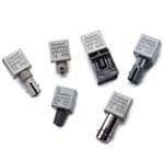
ICGOO电子元器件商城为您提供HFBR-24E2Z由Avago Technologies设计生产,在icgoo商城现货销售,并且可以通过原厂、代理商等渠道进行代购。 HFBR-24E2Z价格参考。Avago TechnologiesHFBR-24E2Z封装/规格:光纤 - 接收器, Fiber Optic Receiver General Purpose 5MBd 4.75 V ~ 5.25 V 。您可以下载HFBR-24E2Z参考资料、Datasheet数据手册功能说明书,资料中有HFBR-24E2Z 详细功能的应用电路图电压和使用方法及教程。
Broadcom Limited 的 HFBR-24E2Z 是一款属于光纤 - 接收器类别的产品,主要应用于短距离数据通信和光纤链路中。以下是该型号的具体应用场景:

1. 工业自动化:HFBR-24E2Z 可用于工业控制系统的信号传输,例如 PLC(可编程逻辑控制器)之间的数据交换,确保高可靠性与抗干扰能力。

2. 医疗设备:在医疗领域,这款接收器可用于需要高精度和低延迟的设备间通信,如超声波机器、核磁共振成像系统等,提供稳定的信号传输。

3. 消费电子:适用于高清音视频传输设备,如家庭影院系统或数字电视中的光纤接口,保证高质量的多媒体体验。

4. 电信网络:用于局域网(LAN)、存储区域网(SAN)或其他内部网络连接,支持高速数据传输并减少电磁干扰。

5. 测试与测量仪器:在精密测试设备中,HFBR-24E2Z 能够实现准确的数据采集与分析,满足实验室环境下的严格要求。

6. 安防监控:为闭路电视(CCTV)系统提供可靠的光纤传输解决方案,确保视频流稳定且清晰。

7. 航空航天与国防:由于其出色的性能和稳定性,该型号也可用于军事通信系统或飞行器内的数据链路。

总之,HFBR-24E2Z 凭借其卓越的灵敏度、宽广的工作温度范围以及紧凑的设计,非常适合各种对可靠性和速度有较高需求的应用场合。
| 参数 | 数值 |
| 产品目录 | |
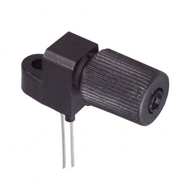
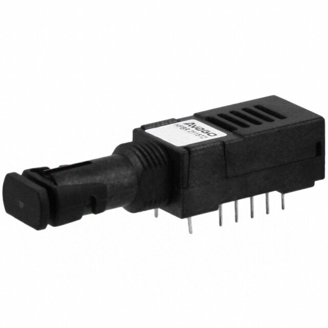
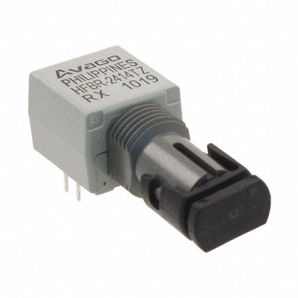
| 描述 | RCVR MOD FIBER OPT IND SC PORT光纤发射器、接收器、收发器 LT RX SC PORT Pb-Fre e |
| 产品分类 | |
| 品牌 | Avago Technologies |
| 产品手册 | |
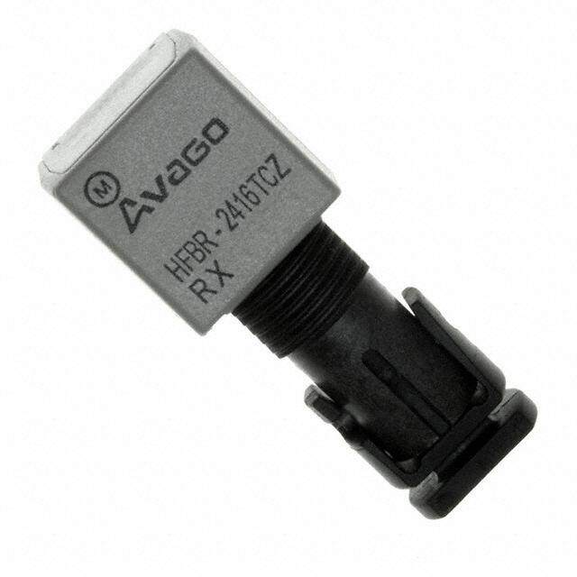
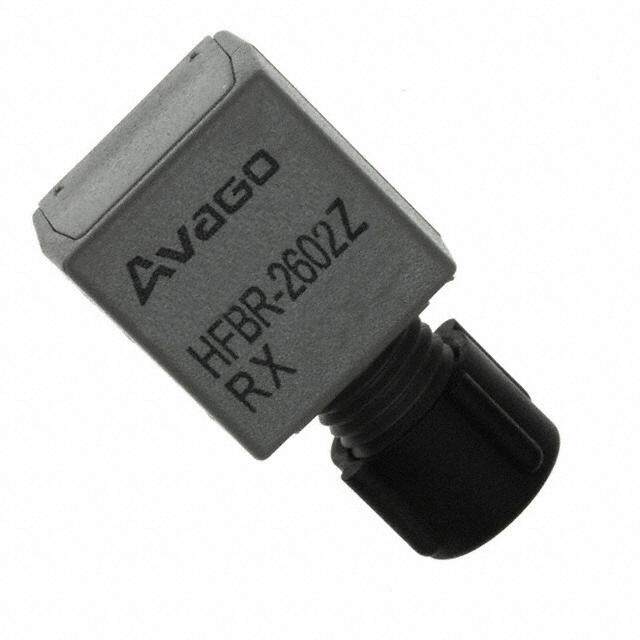
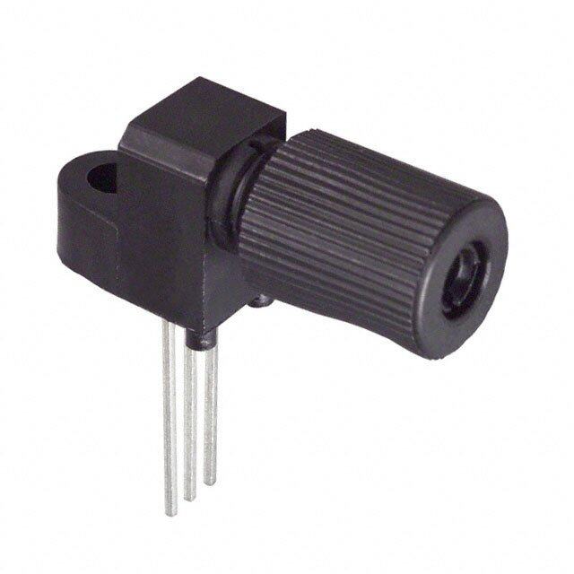
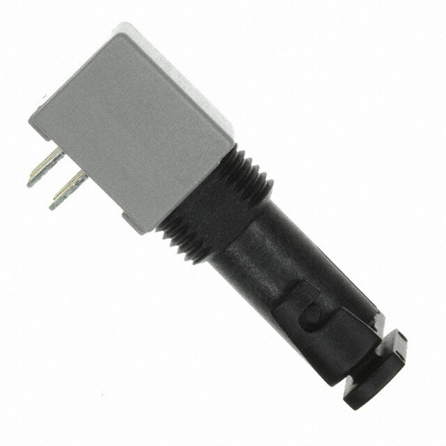
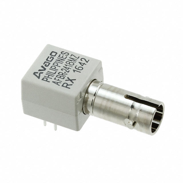
| 产品图片 |
|
| rohs | 符合RoHS无铅 / 符合限制有害物质指令(RoHS)规范要求 |
| 产品系列 | 光纤发射器、接收器、收发器,Avago Technologies HFBR-24E2Z- |
| 数据手册 | http://www.avagotech.com/docs/AV02-0176EN |
| 产品型号 | HFBR-24E2Z |
| 产品 | Receivers |
| 产品种类 | 光纤发射器、接收器、收发器 |
| 其它名称 | 516-2416 |
| 功率-可接受的最小值 | - |
| 商标 | Avago Technologies |
| 外观尺寸或封装类型 | 1 X 9 |
| 安装风格 | Through Hole |
| 封装 | Tube |
| 工作电源电压 | 5 V |
| 工厂包装数量 | 12 |
| 应用 | Ethernet |
| 数据速率 | 5 MBd |
| 最大工作温度 | + 85 C |
| 最大输出电流 | 25 mA |
| 最小工作温度 | - 40 C |
| 标准包装 | 12 |
| 波长 | 820 nm |
| 电压-电源 | 4.75 V ~ 5.25 V |
| 电流-电源 | - |
| 纤维类型 | Multimode |
| 连接器类型 | SC |


- 商务部:美国ITC正式对集成电路等产品启动337调查
- 曝三星4nm工艺存在良率问题 高通将骁龙8 Gen1或转产台积电
- 太阳诱电将投资9.5亿元在常州建新厂生产MLCC 预计2023年完工
- 英特尔发布欧洲新工厂建设计划 深化IDM 2.0 战略
- 台积电先进制程称霸业界 有大客户加持明年业绩稳了
- 达到5530亿美元!SIA预计今年全球半导体销售额将创下新高
- 英特尔拟将自动驾驶子公司Mobileye上市 估值或超500亿美元
- 三星加码芯片和SET,合并消费电子和移动部门,撤换高东真等 CEO
- 三星电子宣布重大人事变动 还合并消费电子和移动部门
- 海关总署:前11个月进口集成电路产品价值2.52万亿元 增长14.8%


PDF Datasheet 数据手册内容提取
HFBR-14xxZ and HFBR-24xxZ Series Low-Cost, 820 nm Miniature Link Fiber Optic Components with ST, SMA, SC, and FC Ports Data Sheet Description Features The 820 nm Miniature Link Series of components is designed RoHS compliant to provide cost-eff ective, high-performance fi ber optic Low-cost transmitters and receivers communication links for information systems and industrial Choice of ST, SMA, SC, or FC ports applications with link distances of several kilometers. With the HFBR-24x6Z, the 125 MHz analog receiver, data rates of up to 820 nm wavelength technology 160 MBaud can be attained. Signal rates up to 160 MBaud Transmitters and receivers are directly compatible with Link distances up to several kilometers popular “industry-standard” connectors: ST, SMA, SC, and FC. Compatible with 50/125 μm, 62.5/125 μm, 100/140 μm, and They are completely specifi ed with multiple fi ber sizes; 200 μm Plastic-Clad Silica (PCS) Fiber including 50/125 μm, 62.5/125 μm, 100/140 μm, and 200 μm. Repeatable ST connections within 0.2 dB typical Products are available in various options. For example, Unique optical port design for effi cient coupling transmitters with the improved protection option P show an increased ESD resistance to the pins. This HFBR-141xPxZ Pick and place, and wave solderable integrated solution is realized by including a Zener diode No board-mounting hardware required parallel to the LED. Wide operating temperature range –40°C to +85°C The HFBR-14x4Z high-power transmitter and HFBR-24x6Z Conductive port option 125 MHz receiver pair up to provide a duplex solution optimized for 100BASE-SX. 100BASE-SX is a Fast Ethernet Applications Standard (100 Mb/s) at 850 nm on multimode fi ber. 100BASE-SX Fast Ethernet on 850 nm Evaluation kits are available for ST products, including transmitter, receiver, eval board, and technical literature. Media/fi ber conversion, switches, routers, hubs, and NICs on 100BASE-SX Local area networks Computer-to-peripheral links and computer monitor links Digital cross connect links Central offi ce switch/PBX links Video links Modems and multiplexers Suitable for Tempest systems Industrial control links Broadcom - 1 -
HFBR-14xxZ and HFBR-24xxZ Series Data Sheet Part Number Guide A/HFBR - x 4 x xaa Z RoHS Compliant 1 Transmitter P Protection improved option 2 Receiver T Threaded port option 4 820 nm Transmitter and C Conductive port receiver option Receiver products M Metal port option 0 SMA, housed 2 TX, standard power 1 ST, housed 4 TX, high power 2 FC, housed 2 RX, 5 MBaud, TTL output E SC, housed 5 TX, high light output power 6 RX, 125 MHz, Analog Output 8 RX, DC to 50 MBaud, Digital Output 9 RX, 100 KBaud to 50 MBaud, Digital Output Available Options HFBR-1402Z HFBR-1404Z HFBR-1412PTZ HFBR-1412PZ HFBR-1412TMZ HFBR-1412TZ HFBR-1412Z HFBR-1414PTZ HFBR-1414PZ HFBR-1414MZ HFBR-1414TZ HFBR-1414Z HFBR-1415PMZ HFBR-1415TZ HFBR-1415Z HFBR-1424Z HFBR-14E4Z HFBR-2402Z HFBR-2406Z HFBR-2412TCZ HFBR-2412TZ HFBR-2412Z HFBR-2416MZ HFBR-2416TCZ HFBR-2416TZ HFBR-2416Z HFBR-2422Z HFBR-24E2Z HFBR-24E6Z AFBR-2408Z AFBR-2418Z AFBR-2418TZ AFBR-2418MZ AFBR-2409Z AFBR-2419Z AFBR-2419TZ AFBR-2419MZ Note: For better readability of the electrical and optical specifi cations, all available options (P, T, C, and M) are covered by the HFBR-x4xxZ product name; exceptions are explicitly noted. Note: AFBR-24x8xZ receivers are designed for data rates from DC up to 50 MBaud. AFBR-24x9xZ supports transmissions from 100 KBaud up to 50 MBaud. Refer to the separate data sheets for details about these digital optical receivers providing CMOS/TTL output logic. Link Selection Guide For additional information about specifi c links, see the individual link descriptions. The HFBR-1415Z can be used for increased power budget or for lower driving current for the same Data Rates and Link Distances. Data Rate Distance (m) Transmitter Receiver Fiber Size (μm) Evaluation Kit (MBaud)1 DC to 5 1500 HFBR-14x2Z HFBR-24x2Z 62.5/125 HFBR-0410Z 20 2700 HFBR-14x4Z/14x5Z HFBR-24x6Z 62.5/125 HFBR-0416Z 20 to 32 2200 HFBR-14x4Z/14x5Z HFBR-24x6Z 62.5/125 HFBR-0416Z DC to 50 2000 HFBR-14x4Z/14x5Z AFBR-24x8xZ 62.5/125 AFBR-0549Z 0.1 to 50 1000 HFBR-14x4Z/14x5Z AFBR-24x9xZ 62.5/125 AFBR-0550Z 20 to 55 1400 HFBR-14x4Z/14x5Z HFBR-24x6Z 62.5/125 HFBR-0416Z 20 to 125 700 HFBR-14x4Z/14x5Z HFBR-24x6Z 62.5/125 HFBR-0416Z 20 to 155 600 HFBR-14x4Z/14x5Z HFBR-24x6Z 62.5/125 HFBR-0416Z 20 to 160 500 HFBR-14x4Z/14x5Z HFBR-24x6Z 62.5/125 HFBR-0416Z 1. The data rate range in the table refers to the evaluation kit documentation. For an analog receiver, like the HFBR-24x6Z, the data rate range depends on the receiver circuit used. Broadcom - 2 -
HFBR-14xxZ and HFBR-24xxZ Series Data Sheet Options In addition to the various port styles available for the HFBR-0400Z series products, there are also several extra options that can be ordered. To order an option, simply place the corresponding option number at the end of the part number. See page 2 for available options. Option P (Protection improved option) Designed to withstand electrostatic discharge (ESD) of 2 kV (HBM) to the pins Available on TX with non-conductive ST and non-conductive threaded ST ports Option T (Threaded Port Option) Allows ST style port components to be panel mounted Compatible with all current makes of ST multimode connectors Mechanical dimensions are compliant with MIL-STD- 83522/13 Maximum wall thickness when using nuts and washers from the HFBR-4411Z hardware kit is 2.8 mm (0.11 inch) Available on all ST ports Option C (Conductive Port Receiver Option) Designed to withstand electrostatic discharge (ESD) of 25 kV to the optical port Signifi cantly reduces eff ect of electromagnetic interference (EMI) on receiver sensitivity Allows designer to separate the signal and conductive port grounds Recommended for use in noisy environments Available on threaded ST port style receivers only The conductive port is connected to Pins 1, 4, 5, and 8 through the Port Grounding Path Insert Option M (Metal Port Option) Nickel plated aluminum connector receptacle Designed to withstand electrostatic discharge (ESD) of 15 kV to the optical port Signifi cantly reduces eff ect of electromagnetic interference (EMI) on receiver sensitivity Allows designer to separate the signal and metal port grounds Recommended for use in very noisy environments Available on ST and threaded ST ports The metal port is connected to Pins 1, 4, 5, and 8 through the Port Grounding Path Insert Broadcom - 3 -
HFBR-14xxZ and HFBR-24xxZ Series Data Sheet Applications Support Guide This section gives the designer information necessary to use the 820 nm Miniature Link Series components to make a functional optical transmission link. Broadcom off ers evaluation kits for hands-on experience with fi ber optic products as well as a wide range of application notes complete with circuit diagrams and board layouts. Furthermore, Broadcom’s application support group is always ready to assist with any design consideration. Application Literature Title Description Application Note 1065 Complete Solutions for IEEE 802.5J Fiberoptic Token Ring Application Note 1121 DC to 32 MBaud Fiberoptic Solutions Application Note 1122 2 to 70 MBaud Fiberoptic Solutions Application Note 1123 20 to 160 MBaud Fiberoptic Solutions Application Note 1137 Generic Printed Circuit Layout Rules Evaluation Kits Broadcom off ers fi ber optic kits that facilitate a simple means to evaluate and experience our products. These fi ber optic kits contain all the components and tools required for customers to quickly evaluate and access the value of our products within their respective applications. HFBR-0410Z ST Evaluation Kit: DC to 5 MBaud 820 nm Fiber Optic Eval Kit Contains the following: One HFBR-1412Z transmitter One HFBR-2412Z receiver Eval board Related literature HFBR-0416Z Evaluation Kit: 125 MBaud 820 nm Fiber Optic Eval Kit Contains the following: One HFBR-1414Z transmitter One HFBR-2416Z receiver Eval board Related literature AFBR-0549Z Evaluation Kit: DC to 50 MBaud 820 nm Fiber Optic Eval Kit Contains the following: One HFBR-1414PTZ transmitter One AFBR-2418TZ receiver Eval board Related literature Broadcom - 4 -
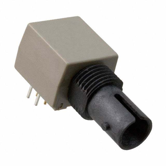
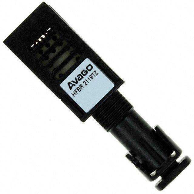
HFBR-14xxZ and HFBR-24xxZ Series Data Sheet AFBR-0550Z Evaluation Kit: Up to 50 MBaud 820 nm Fiber Optic Eval Kit Contains the following: One HFBR-1414PTZ transmitter One AFBR-2419TZ receiver Eval board Related literature Package and Handling Information Package Information All transmitters and receivers of the 820 nm Miniature Link Series are housed in a low-cost, dual-inline package that is made of high strength, heat resistant, chemically resistant, and UL 94V-O fl ame retardant plastic (UL File #E121562). The transmitters are easily identifi ed by the light grey color connector port. The receivers are easily identifi ed by the dark grey color connector port. (Black color for conductive port). The package is designed for pick and place and wave soldering so it is ideal for high volume production applications. Handling and Design Information Each part comes with a protective port cap or plug covering the optics. Note: This plastic or rubber port cap is made to protect the optical path during assembly. It is not meant to remain on the part for a long period. These caps/plugs will vary by port style. When soldering, it is advisable to leave the protective cap on the unit to keep the optics clean. Good system performance requires clean port optics and cable ferrules to avoid obstructing the optical path. Clean compressed air often is suffi cient to remove particles of dirt; methanol on a cotton swab also works well. Recommended Chemicals for Cleaning/Degreasing 820 nm Miniature Link Products Alcohols: methyl, isopropyl, isobutyl. Aliphatics: hexane, heptane, Other: soap solution, naphtha. Do not use partially halogenated hydrocarbons (such as 1.1.1 trichloroethane), ketones (such as MEK), acetone, chloroform, ethyl acetate, methylene dichloride, phenol, methylene chloride, or N-methylpyrolldone. Also, Broadcom does not recommend the use of cleaners that use halogenated hydrocarbons because of their potential environmental harm. Broadcom - 5 -
HFBR-14xxZ and HFBR-24xxZ Series Data Sheet Mechanical Dimensions (SMA Port) HFBR-x40xZ 1/4 - 36 UNS 2A THREAD (01.25.07) AVAGOCOUNTRY OFORIGINHFBR-x40xZTX/RX YYWW 22.2 (0.87) 6.35 12.7 (0.25) (0.50) (06.2.45) DIA. (03.1.64) 5.1 (01.04.02) (0.20) 3.81 (0.15) 1.27 2.54 (0.05) (0.10) PINS 1,4,5,8 0.51 X 0.38 2.54 (0.020 X 0.015) 4 5 (0.10) 3 6 PINS 2,3,6,7 27 (00.0.4168) DIA. 1 8 PIN NO. 1 INDICATOR Dimensions in mm (inches) Mechanical Dimensions (ST Port) HFBR-x41xZ 4.9 max. (102.5.70) AVAGOCOUNTRY OFORIGINHFBR-x41xZTX/RX YYWW (0.193) 27.2 8.2 (1.07) (0.32) 6.35 12.7 (0.25) (0.50) 7.0 DIA. 3.6 10.2 (0.28) (0.14) 5.1 (0.40) (0.20) 3.81 (0.15) 1.27 2.54 (0.05) (0.10) PINS 1,4,5,8 2.54 0.51 X 0.38 4 5 (0.10) (0.020 X 0.015) 3 6 27 PINS 2,3,6,7 Ø0.46 1 8 (0.018) PIN NO. 1 INDICATOR Dimensions in mm (inches) Broadcom - 6 -
HFBR-14xxZ and HFBR-24xxZ Series Data Sheet Mechanical Dimensions (Metal ST Port) HFBR-x41xMZ 4.9 MAX. (0.193) (01.25.07) AVAGOCOUNTRY OFORIGINHFBR-x41xMZTX/RX YYWW (08.3.43) 27.2 (1.07) 6.35 (0.25) 12.7 (0.50) 7.0 DIA. 3.6 10.2 (0.28) (0.14) 5.1 (0.40) (0.20) 3.81 (0.15) 2.54 1.27 (0.10) (0.05) 2.54 PINS 1,4,5,8 45 (0.10) 0.51 × 0.38 (0.020 × 0.015) 3 6 2 7 PINS 2,3,6,7 0.46 DIA. 18 (0.018) DIA. PIN NO. 1 INDICATOR Dimensions in mm (inches) Mechanical Dimensions (Threaded ST Port) HFBR-x41xTZ 5.1 (0.20) 4.9 MAX. (0.193) (01.25.07) AVAGOCOUNTRY OFORIGINHFBR-x41xTZTX/RX YYWW 8.4 (0.33) 27.2 7.6 (1.07) (0.30) 6.35 12.7 (0.25) (0.50) 7.1 DIA. 3.6 10.2 (0.28) (0.14) 5.1 (0.40) (0.20) 3/8 - 32 UNEF - 2A 3.81 (0.15) 1.27 2.54DIA. (0.05) (0.10) PINS 1,4,5,8 0.51 × 0.38 2.54 (0.020 × 0.015) 45 (0.10) 36 PINS 2,3,6,7 27 (00.0.4168)DIA. 18 PIN NO. 1 INDICATOR Dimensions in mm (inches) Broadcom - 7 -
HFBR-14xxZ and HFBR-24xxZ Series Data Sheet Mechanical Dimensions (FC Port) HFBR-x42xZ M8 x 0.75 6G THREAD (METRIC) (01.25.07) AVAGOCOUNTRY OFORIGINHFBR-x42xZTX/RX YYWW 19.6 (0.77) 12.7 (0.50) 7.9 3.6 10.2 (0.31) (0.14) 5.1 (0.40) (0.20) 3.81 (0.15) 2.54 (0.10) 0.51 X 0.38 PINS 1,4,5,8 45 (0.020 X 0.015) 36 27 18 PINS 2,3,6,7Ø 0.46 (0.018) 2.54 (0.10) PIN NO. 1 INDICATOR Dimensions in mm (inches) Mechanical Dimensions (SC Port) HFBR-x4ExZ AVAGOCOUNTRY OFORIGINHFBR-x4ExZTX/RX YYWW 28.65 (1.128) 12.7 6.35 (0.50) (0.25) 10.0 10.38 (0.394) 3.60 (0.409) (0.14) 5.1 15.95 (0.20) 3.81 (0.628) (0.15) 1.27 2.54 (0.05) (0.10) 2.54 (0.10) PINS 1,4,5,8 0.51 × 0.38 4 5 (0.020 × 0.015) 3 12.7 6 27 (0.50) PINS 2,3,6,7 1 8 Ø 0.46 (0.018) PIN NO. 1 INDICATOR Dimensions in mm (inches) Broadcom - 8 -
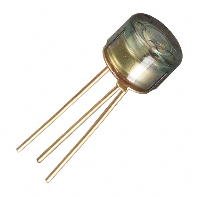
HFBR-14xxZ and HFBR-24xxZ Series Data Sheet Cross-Sectional View LED OR DETECTOR IC LENS–SPHERE (ON TRANSMITTERS ONLY) HOUSING LENS–WINDOW CONNECTOR PORT HEADER EPOXY BACKFILL Figure 1: HFBR-x41xTZ ST Series Cross-Sectional View Panel Mount Hardware HFBR-4401Z: for SMA Ports HFBR-4411Z: for ST Ports 1/4 - 36 UNEF - 3/8 - 32 UNEF - DATE CODE 2B THREAD 2B THREAD 0.2 IN. PART NUMBER (07.3.8170) DIA. 1.65 (102..5700) DIA. AVAGOCOUNTRY OFORIGINHFBR-x40xZTX/RX YYWW HEX-NUT (0.065) HEX-NUT (01.0.6655) 32/A8 T -H 3R2E UANDEINF G- 1 THREAD AVAILABLE 7.87 TYP. (0.310) DIA. 14.27 TYP. WALL NUT (0.563) DIA. 6.61 (0.260) DIA. 0.14 10.41 MAX. (0.005) (0.410) DIA. 0.46 WASHER (0.018) WASHER WASHER (Each HFBR-4401Z and HFBR-4411Z kit consists of 100 nuts and 100 washers). Dimensions in mm (inches) Port Cap Hardware HFBR-4402Z: 500 SMA Port Caps HFBR-4120Z: 500 ST Port Plugs Broadcom - 9 -
HFBR-14xxZ and HFBR-24xxZ Series Data Sheet Typical Link Data The following technical data is taken from 5 MBaud and 155 MBaud link using the 820 nm Miniature Link Series. This data is meant to be regarded as an example of typical link performance for a given design and does not call out any link limitations. 5 MBaud Link (HFBR-14xxZ/24x2Z) Link Performance –40°C to +85°C unless otherwise specifi ed Parameter Symbol Min. Typ. Max. Unit Conditions Reference Optical Power Budget with 50/125 μm OPB50 4.2 9.6 dB HFBR-14x4Z/24x2Z Note 1 fi ber NA = 0.2 Optical Power Budget with 62.5/125 μm OPB62.5 8.0 15 dB HFBR-14x4Z/24x2Z Note 1 fi ber NA = 0.27 Optical Power Budget with 100/140 μm OPB100 8.0 15 dB HFBR-14x2Z/24x2Z Note 1 fi ber NA = 0.30 Optical Power Budget with 200 μm fi ber OPB200 13.0 20 dB HFBR-14x2Z/24x2Z Note 1 NA = 0.37 Data Rate DC 5 MBaud Note 2 Propagation Delay LOW to HIGH tPLH 72 ns TA = +25°C Propagation Delay HIGH to LOW tPHL 46 ns PR = –21 dBm peak Figures Fiber cable length 6, 7, 8 = 1 m System Pulse Width Distortion tPLH – tPHL 26 ns Bit Error Rate BER 10-9 Data rate < 5 MBaud PR > –24 dBm peak Notes: 1. Optical Power Board at TA = –40°C to +85°C, VCC = 5.0Vdc, IF ON = 60 mA. PR = –24 dBm peak. 2. Data rate limit is based on these assumptions: a. 50% duty factor modulation, e.g., Manchester I or BiPhase Manchester II b. Continuous data c. PLL Phase Lock Loop demodulation d. TTL threshold. Broadcom - 10 -
HFBR-14xxZ and HFBR-24xxZ Series Data Sheet 5 MBaud Logic Link Design The resistor R1 is the only signifi cant element in the drive circuit (see Figure 2) that limits the current through the LED, apart from the gate´s output port. Depending on the actual gate used, the voltage drop on the output port V could be neglected. The port forward voltage value, V , of the LED depends on the desired LED current and on the temperature (see Figure 9). Make sure you F take this behavior into account for the calculations. The curves in Figure 3, Figure 4, and Figure 5 are constructed assuming no inline splice or any additional system loss. Besides fi ber attenuation, for correct power budget calculation, make sure you take into account the eff ect of bending, humidity, ambient temperature, aging and other relevant infl uences. All these additional losses reduce the achievable link distance accordingly. For calculating the LED's aging eff ect, an additional loss of about 1.5 dB is recognized. The following example will illustrate the technique for selecting the appropriate value of I and R1: F R1=VCC -VF IF Maximum distance required = 2000 meters by using HFBR-14x4Z/24x2Z logic link with 62.5/125 μm fi ber. Figure 4 shows the “worst-case” drive current of about 43 mA for reaching a distance of about 2000 meters. Figure 9 shows the transmitter forward voltage of about V = 1.62V. If the typical circuit confi guration (Figure 2) is used at V = 5.0 F cc V, the resistor value “R1” should be choosen to 78.6Ω (3.38 V/43 mA) for reaching driver current of about 43 mA. Page 16 shows the guaranteed HFBR-14x4Z´s optical output power limit of -16.0 dBm (for driver current of 60 mA) over the entire temperature range. Figure 10 shows the normalized typical output power. When the transmitter will be driven with 43 mA the optical output power is about 0.70 or –1.55 dB lower than at 60 mA. With an assumed fi ber attenuation of 3.2 dB/km and the reduced driver current of 43 mA, the minimum optical output power at fi ber end is about –24 dBm, which is equal to the receiver sensitivity over the entire temperature range. For balancing the individual additional system losses, the driver current must be increased accordingly. Figure 2. Typical Circuit Confi guration TTL DATA OUT +5 V SELECT R TO SETI HFBR-14xxZ HFBR-24x2Z 1 F TRANSMITTER RECEIVER I R1 F 2 2 6 1 K 73 T R 6 RL VCC 0.1 μF 7 &3 DATA IN ½ 75451 TRANSMISSION DISTANCE = Note: A bypass capacitor (0.01 μF to 0.1 μF ceramic) must be connected from pin 2 to pin 7 of the receiver. Total lead length between both ends of the capacitor and the pins should not exceed 20 mm. The following diagrams (Figure 3 to Figure 5) serve as an aid in Link Design and are based on theoretical calculations. For broad use, no additional eff ects such as aging were taken into account. The additional losses and the individual safety buff er values should be added separately. These diagrams refl ect the pure viewing of power budget and do not allows conclusions about the actual link quality. Overdrive: Maximum optical output power of Tx combined with receiver sensitivity of –10 dBm over the entire temperature range. Typical 25°C: Typical optical output power of Tx combined with receiver sensitivity of –25.4 dBm at T = 25°C. A Worst Case: Minimum optical output power of Tx combined with receiver sensitivity of –24 dBm over the entire temperature range. Broadcom - 11 -
HFBR-14xxZ and HFBR-24xxZ Series Data Sheet Figure 3: Typical HFBR-14x4xZ/HFBR-24x2xZ Link with Figure 4: Typical HFBR-14x4xZ/HFBR-24x2xZ Link with 100/140 μm Fiber 62.5/125 μm Fiber 100 100 90 90 A) 80 A) 80 m m nt ( 70 OWVoErRsDt RCaIVsEe nt ( 70 OVERDRIVE er curre 5600 TYPICAL, 25°C er curre 5600 TWYPorICstA CLa, 2se5°C smitt 40 smitt 40 n n Tra 30 Tra 30 al al pic 20 pic 20 y y T 10 T 10 0 0 0 1 2 3 4 0 1 2 3 4 Fiber Length (km) Fiber Length (km) (Fiber Attenuation: 4 dB/km) (Fiber Attenuation: 3.2 dB/km) Figure 5: Typical HFBR-14x4xZ/HFBR-24x2xZ Link with 50/125 μm Fiber 100 90 A) 80 Worst Case m TYPICAL, 25°C t ( 70 n e rr 60 u er c 50 t t mi 40 s n a Tr 30 al pic 20 y T 10 0 0 1 2 3 4 Fiber Length (km) (Fiber Attenuation: 2.7 dB/km) Figure 6: Typical Propagation Delay Times of Link (HFBR-14x4Z/ Figure 7: Typical Pulse Width Distortion of Link (HFBR-14x4Z/HF- HFBR-24x2Z) measured at TA=25°C, 5 MBaud, and with 1m of Cable BR-24x2Z) measured at TA=25°C, 5 MBaud, and with 1m of Cable 75 55 70 tPLH (TYP) @ 25°C 50 65 sn – YALED 60 45 NOITA 55 sn – N 40 G 50 O OPORP - t RO LHPH 443505 tPHL (TYP) @ 25°C ITROTSID ZRN – tD 3350 LP t 30 25 25 20 20 -22 -21 -20 -19 -18 -17 -16 -15 -14 -13 -12 -22 -21 -20 -19 -18 -17 -16 -15 -14 -13 -12 PR – RECEIVER POWER – dBm PR – RECEIVER POWER – dBm Broadcom - 12 -
HFBR-14xxZ and HFBR-24xxZ Series Data Sheet Figure 8: System Propagation Delay Test Circuit and Waveform Timing Defi nitions PULSE +15V RESISTOR VALUE AS NEEDED FOR GEN SETTING OPTICAL POWER OUTPUT R FROM RECEIVER END OF TEST CABLE S ½ 75451 1N4150 100 ns PULSE REPETITION 100 ns 2, 6, 7 INPUT FREQ = 1 MHz RS 3 IF 50% t t PHLT PHLT TRANSMITTER INPUT (I F) P 50% T t PHL PT -FRTOEMST 1 C-MABELTEER +5 V ANTIAMLYINSIGS MtAPHXL MtPIHNL MtAPHXL MIN EQUIPMENT 2 RL 560 OUTPUT eg. SCOPE V 5V 76 & 3 0.1 μF 15 pF+ VO O 1.50V HFBR-2412Z RECEIVER 155 MBaud Link (HFBR-14x4Z/24x6Z) Typical Link Performance Parameter Symbol Min. Typ. [1, 2] Max. Unit Conditions Reference Optical Power Budget with OPB50 13.9 dB NA = 0.2 Note 2 50/125 μm fi ber Optical Power Budget OPB62 17.7 dB NA = 0.27 with 62.5/125 μm fi ber Optical Power Budget OPB100 17.7 dB NA = 0.30 with 100/140 μm fi ber Optical Power Budget OPB200 22.0 dB NA = 0.35 with 200 μm PCS fi ber Data Format 20% to 80% Duty 20 160 MBaud Factor System Pulse Width |tPLH − tPHL| 1 ns PR = –7 dBm peak 1 m Distortion 62.5/125 μm fi ber Bit Error Rate BER 10-9 Data rate < 100 MBaud Note 2 PR > –31 dBm peak Notes: 1. Typical data at TA = +25°C, VCC = 5.0Vdc, PECL serial interface. 2. Typical OPB was determined at a probability of error (BER) of 10-9. Lower probabilities of error can be achieved with short fi bers that have less optical loss. Broadcom - 13 -
HFBR-14xxZ and HFBR-24xxZ Series Data Sheet HFBR-14x2Z/14x4Z/14x5Z Low-Cost High-Speed Transmitters Description Note: Parameters “reverse input voltage” and “diode capaci- tance” for “HFBR-141xPxZ” transmitters deviate from the non The HFBR-14xxZ fi ber optic transmitter contains an 820 nm P-parts. AlGaAs emitter capable of effi ciently launching optical power into four diff erent optical fi ber sizes: 50/125 μm, 62.5/125 μm, Consistent coupling effi ciency is assured by the double-lens 100/140 μm, and 200 μm Plastic-Clad Silica (PCS). This allows optical system (Figure 1 on page 9). Power coupled into any of the designer fl exibility in choosing the fi ber size. The HFBR- the three fi ber types varies less than 5 dB from part to part at 14xxZ is designed to operate with the Broadcom Ltd. HFBR- a given drive current and temperature. Consistent coupling ef- 24xxZ fi ber optic receivers. fi ciency reduces receiver dynamic range requirements, which allows for longer link lengths. The HFBR-14xxZ transmitter’s high coupling effi ciency al- lows the emitter to be driven at low current levels resulting in low power consumption and increased reliability of the Housed Product transmitter. The HFBR-14x4Z high power transmitter is opti- mized for small size fi ber and typically can launch -15.8 dBm PIN FUNCTION optical power at 60 mA into 50/125 μm fi ber and -12 dBm ANODE 2, 6, 7 11 NC 2 ANODE into 62.5/125 μm fi ber. The HFBR-14x2Z standard transmitter CATHODE 3 32 CATHODE 41 NC typically can launch -12 dBm of optical power at 60 mA into 51 NC 6 ANODE 100/140 μm fi ber cable. It is ideal for large size fi ber such as 72 ANODE 100/140 μm. The high launched optical power level is useful 4 5 81 NC for systems where star couplers, taps, or inline connectors cre- 3 6 2 7 ate large fi xed losses. 1 8 For 820 nm Miniature Link transmitters with protection im- BOTTOM VIEW PIN 1 INDICATOR proved option “P” a Zener diode parallel to the LED was imple- mented. Therefore, a higher ESD capability could be attained. NOTES: 1. PINS 1, 4, 5, AND 8 ARE ELECTRICALLY CONNECTED. 2. PINS 2, 6, AND 7 ARE ELECTRICALLY CONNECTED TO THE HEADER. Regulatory Compliance - Targeted Specifi cations Feature Performance Reference Electrostatic Discharge (ESD) Class 1C (>1000V, <2000V) - Human Body Model Note 1, 4 Class 1B (>500V, <1000V) - Human Body Model Note 1, 2 Absolute Maximum Ratings Parameter Symbol Min. Max. Unit Reference Storage Temperature TS –55 +85 °C Operating Temperature TA –40 +85 °C Lead Soldering Cycle Temp +260 °C Time 10 sec Forward Input Current Peak IFPK 200 mA Note 3 dc IFdc 100 mA Reverse Input Voltage VBR 1.8 V 0.3 V Note 4 Notes: 1. ESD capability for all pins HBM (Human Body Model) according JEDEC JESD22-A114. 2. Valid for not protection improved transmitter option 3. For IFPK > 100 mA, the time duration should not exceed 2 ns. 4. Only valid for HFBR-141xPxZ (Protection improved option). Broadcom - 14 -
HFBR-14xxZ and HFBR-24xxZ Series Data Sheet Electrical/Optical Specifi cations –40°C to +85°C unless otherwise specifi ed. Parameter Symbol Min. Typ. [2] Max. Unit Conditions Reference Forward Voltage VF 1.48 1.70 2.09 V IF = 60 mA dc Figure 9 1.84 IF = 100 mA dc Forward Voltage Temperature ΔVF/ΔT –0.22 mV/K IF = 60 mA dc Figure 9 Coeffi cient –0.18 IF = 100 mA dc Reverse Input Voltage VBR 1.8 3.8 V IF = –100 μA dc 0.3 0.7 V IF = –100 μA dc Note 10 Peak Emission Wavelength lP 792 820 865 nm Diode Capacitance CT 55 pF V = 0, f = 1 MHz 70 pF V = 0, f = 1 MHz Note 10 Optical Power Temperature ΔPT/ΔT –0.006 dB/K I = 60 mA dc Coeffi cient –0.010 I = 100 mA dc Thermal Resistance ΘJA 490 K/W Notes 3, 8 14x2Z Numerical Aperture NA 0.49 14x4Z Numerical Aperture NA 0.31 14x2Z Optical Port Diameter D 290 μm Note 4 14x4Z Optical Port Diameter D 150 μm Note 4 HFBR-14x2Z Output Power Measured Out of 1 Meter of Cable Parameter Symbol Min. Typ. Max. Unit Conditions Reference 50/125 μm Fiber Cable PT50 –21.8 –18.8 –16.8 dBm peak TA = +25°C, IF = 60 mA Notes 5, 6, 9 –22.8 –15.8 dBm peak TA = –40°C to +85°C, IF = 60 mA –20.3 –16.8 –14.4 dBm peak TA = +25°C, IF = 100 mA Figure 10 –21.9 –13.8 dBm peak TA = –40°C to +85°C, IF = 100 mA 62.5/125 μm Fiber Cable PT62 –19.0 –16.0 –14.0 dBm peak TA = +25°C, IF = 60 mA –20.0 –13.0 dBm peak TA = –40°C to +85°C, IF = 60 mA –17.5 –14.0 –11.6 dBm peak TA = +25°C, IF = 100 mA –19.1 –11.0 dBm peak TA = –40°C to +85°C, IF = 100 mA 100/140 μm Fiber Cable PT100 –15.0 –12.0 –10 dBm peak TA = +25°C, IF = 60 mA –16.0 –9.0 dBm peak TA = –40°C to +85°C, IF = 60 mA –13.5 –10.0 –7.6 dBm peak TA = +25°C, IF = 100 mA –15.1 –7.0 dBm peak TA = –40°C to +85°C, IF = 100 mA 200 μm PCS Fiber Cable PT200 –10.0 –7.0 –5.0 dBm peak TA = +25°C, IF = 60 mA –11.0 –4.0 dBm peak TA = –40°C to +85°C, IF = 60 mA –8.5 –5.0 –2.6 dBm peak TA = +25°C, IF = 100 mA –10.1 –2.0 dBm peak TA = –40°C to +85°C, IF = 100 mA CAUTION: The small junction sizes inherent to the design of these components increase the components’ susceptibility to damage from electrostatic discharge (ESD). It is advised that normal static precautions be taken in handling and assembly of these components to prevent damage and/or degradation which may be induced by ESD. Broadcom - 15 -
HFBR-14xxZ and HFBR-24xxZ Series Data Sheet HFBR-14x4Z Output Power Measured out of 1 Meter of Cable Parameter Symbol Min. Typ. [2] Max. Unit Conditions Reference 50/125 μm Fiber Cable PT50 –18.8 –15.8 –13.8 dBm peak TA = +25°C, IF = 60 mA Notes 5, 6, 9 NA = 0.2 –19.8 –12.8 dBm peak TA = –40°C to +85°C, IF = 60 mA –17.3 –13.8 –11.4 dBm peak TA = +25°C, IF = 100 mA Figure 10 –18.9 –10.8 dBm peak TA = –40°C to +85°C, IF = 100 mA 62.5/125 μm Fiber Cable PT62 –15.0 –12.0 –10.0 dBm peak TA = +25°C, IF = 60 mA NA = 0.275 –16.0 –9.0 dBm peak TA = –40°C to +85°C, IF = 60 mA –13.5 –10.0 –7.6 dBm peak TA = +25°C, IF = 100 mA –15.1 –7.0 dBm peak TA = –40°C to +85°C, IF = 100 mA 100/140 μm Fiber Cable PT100 –11.5 –8.5 –6.5 dBm peak TA = +25°C, IF = 60 mA NA = 0.3 –12.5 –5.5 dBm peak TA = –40°C to +85°C, IF = 60 mA –10.0 –6.5 –4.1 dBm peak TA = +25°C, IF = 100 mA –11.6 –3.5 dBm peak TA = –40°C to +85°C, IF = 100 mA 200 μm PCS Fiber Cable PT200 –7.5 –4.5 –2.5 dBm peak TA = +25°C, IF = 60 mA NA = 0.37 –8.5 –1.5 dBm peak TA = –40°C to +85°C, IF = 60 mA –6.0 –2.5 –0.1 dBm peak TA = +25°C, IF = 100 mA –7.6 0.5 dBm peak TA = –40°C to +85°C, IF = 100 mA HFBR-14x5Z Output Power Measured out of 1 Meter of Cable Parameter Symbol Min. Typ. Max. Unit Conditions Reference 50/125 μm Fiber Cable PT50 –16.5 –14.3 –11.5 dBm peak TA = +25°C, IF = 60 mA Notes 5, 6, 9 NA = 0.2 –17.5 –10.5 dBm peak TA = –40°C to 85°C, IF = 60 mA 62.5/125 μm Fiber Cable PT62 –12.0 –10.5 –8.0 dBm peak TA = +25°C, IF = 60 mA Figure 10 NA = 0.275 –13.0 –7.0 dBm peak TA = –40°C to 85°C, IF = 60 mA 200 μm Fiber Cable PT200 –6.0 –3.6 0.0 dBm peak TA = +25°C, IF = 60 mA NA = 0.37 –7.0 1.0 dBm peak TA = –40°C to 85°C, IF = 60 mA 14x2Z/14x4Z/14x5Z Dynamic Characteristics Parameter Symbol Min. Typ. [2] Max. Unit Conditions Reference Rise Time, Fall Time tr, tf 4.0 6.5 ns IF = 60 mA Note 7 (10% to 90%) No pre-bias Figure 11 Rise Time, Fall Time tr, tf 3.0 ns IF = 10 to 100 mA Figure 12 (10% to 90%) Pulse Width Distortion PWD 0.5 ns Figure 12 Notes: 1. For IFPK > 100 mA, the time duration should not exceed 2 ns. 2. Typical data at TA = +25°C. 3. Thermal resistance is measured with the transmitter coupled to a connector assembly and mounted on a printed circuit board. 4. D is measured at the plane of the fi ber face and defi nes a diameter where the optical power density is within 10 dB of the maximum. 5. PT is measured with a large area detector at the end of 1 meter of mode stripped cable, with an ST precision ceramic ferrule (MILSTD- 83522/13) for HFBR- 141xZ, and with an SMA 905 precision ceramic ferrule for HFBR-140xZ. 6. When changing mW to dBm, the optical power is referenced to 1 mW. Optical Power P(dBm) = 10log (P(mW) / 1 mW) 7. Pre-bias is recommended if signal rate >10 MBaud, see recommended drive circuit in Figure 11. 8. Pins 2, 6, and 7 are welded to the anode header connection to minimize the thermal resistance from junction to ambient. To further reduce the thermal resistance, the anode trace should be made as large as is consistent with good RF circuit design. 9. Fiber NA is measured at the end of 2 meters of mode stripped fi ber, using the far-fi eld pattern. NA is defi ned as the sine of the half angle, determined at 5% of the peak intensity point. When using other manufacturer’s fi ber cable, results will vary due to diff ering NA values and specifi cation methods. 10. Only valid for HFBR-141xPxZ (Protection improved option). Broadcom - 16 -
HFBR-14xxZ and HFBR-24xxZ Series Data Sheet All HFBR-14XXZ LED transmitters are classifi ed as IEC 825-1 Accessible Emission Limit (AEL) Class 1 based upon the current proposed draft scheduled to go in to eff ect on January 1, 1997. AEL Class 1 LED devices are considered eye safe. Contact your Broadcom Ltd. sales representative for more information. CAUTION: The small junction sizes inherent to the design of these components increase the components’ susceptibility to damage from electrostatic discharge (ESD). It is advised that normal static precautions be taken in handling and assembly of these components to prevent damage and/or degradation which may be induced by ESD. Figure 9: Typical Forward Voltage and Current Characteristics Figure 10: Normalized Typical Transmitter Output vs. Forward Current 100 2 3.0 90 1.8 B) WARD CURRENT (mA) 4567800000 mA) - RELATIVE POWER RATIO 0111....82461 02-01..0.80 mA) RELATIVE POWER RATIO (d FOR 30 85°C P(If) -P(60 00..46 -4.0 P(If) - P(60 20 25°C 0.2 -7.0 -40°C 10 0 1.2 1.3 1.4 1.5 1.6 1.7 1.8 1.9 2 2.1 2.2 0 10 20 30 40 50 60 70 80 90 100 FORWARD VOLTAGE (V) FORWARD CURRENT (mA) Broadcom - 17 -
HFBR-14xxZ and HFBR-24xxZ Series Data Sheet Recommended Transmitter Driver Circuitry Transmitter R1 R2 R3 C3 HFBR-14x2Z/x4Z/x5Z 33Ω 33Ω 270Ω 75 pF Figure 11: Recommended Drive Circuit TXVCC = 5.0V C1 C2 HFBR-14x2Z/x4Z/x5Z 2 AN2 10 μF 100 nF 6 AN6 7 AN7 LL 3 CAT 1 IC1A GND GND Tx 3 3 C 8541 2 R2 4 IC1B R1 12 IC1D 6 11 5 GND Data 13 R3 9 IC1C 8 10 GND 74ACT[Q]00MTC Note: The component values shown in the table create a typical driver current of 60mA (peak). An individual check of the optical output signal quality of the used optic transmitter is recommended during the circuit design. Figure 12: Test Circuit for Measuring tr, tf Agilent 81130A PULSE/PATTERN GENERATOR GND OUT SMA measuring cable (50Ω) O/E CONVERTER HIGH SPEED Silicon PIN photo diode OSCILLOSCOPE (50Ω terminated) (50Ω terminated) Broadcom - 18 -
HFBR-14xxZ and HFBR-24xxZ Series Data Sheet HFBR-24x2Z Low-Cost 5 MBaud Receiver Description The HFBR-24x2Z fi ber optic receiver is designed to operate with the Broadcom Ltd. HFBR-14xxZ fi ber optic transmitter and 50/125 μm, 62.5/125 μm, 100/140 μm, and 200 μm Plastic-Clad Silica (PCS) fi ber optic cable. Consistent coupling into the receiver is assured by the lensed optical system (Figure 1). Response does not vary with fi ber size ≤ 0.100 μm. The HFBR-24x2Z receiver incorporates an integrated photo IC containing a photodetector and dc amplifi er driving an open- collector Schottky output transistor. The HFBR-24x2Z is designed for direct interfacing to popular logic families. The absence of an internal pull-up resistor allows the open-collector output to be used with logic families such as CMOS requiring voltage excursions much higher than V . CC Both the open-collector Data output Pin 6 and V Pin 2 are referenced to Com Pins 3 and 7. The Data output allows busing, CC strobing and wired OR circuit confi gurations. The transmitter is designed to operate from a single +5V supply. It is essential that a bypass capacitor (100 nF ceramic) be connected from Pin 2 (V ) to Pin 3 (circuit common) of the receiver. CC Housed Product 2 V 6 DcAcTA PIN FUNCTION 11 NC 7 & 3 COMMON 232 VCOCCM (5MVO) N 41 NC 4 5 51 NC 3 6 6 DATA 2 7 72 COMMON 1 8 81 NC BOTTOM VIEW PIN 1 INDICATOR NOTES: 1. PINS 1, 4, 5, AND 8 ARE ELECTRICALLY CONNECTED. 2. PINS 3 AND 7 ARE ELECTRICALLY CONNECTED TO THE HEADER. Absolute Maximum Ratings Parameter Symbol Min. Max. Unit Reference Storage Temperature TS –55 +85 °C Operating Temperature TA –40 +85 °C Lead Soldering Cycle Temp +260 °C Note 1 Time 10 sec Supply Voltage VCC –0.5 +7.0 V Output Current IO 25 mA Output Voltage VO –0.5 +18.0 V Output Collector Power Dissipation PO AV 40 mW Fan Out (TTL) N 5 Note 2 Notes: 1. 2.0 mm from where leads enter case. 2. 8 mA load (5 x 1.6 mA), RL = 560Ω. Broadcom - 19 -
HFBR-14xxZ and HFBR-24xxZ Series Data Sheet Electrical/Optical Characteristics –40°C to + 85°C unless otherwise specifi ed. Fiber sizes with core diameter ≤ 100 μm and N/A ≤ 0.35, 4.75V ≤ V ≤ 5.25V. CC Parameter Symbol Min. Typ. [3] Max. Unit Conditions Reference High Level Output Current IOH 5 250 μA VO = 18, PR < –40 dBm Low Level Output Voltage VOL 0.4 0.5 V IO = 8 m, PR > –24 dBm High Level Supply Current ICCH 3.5 6.3 mA VCC = 5.25 V, PR < –40 dBm Low Level Supply Current ICCL 6.2 10 mA VCC = 5.25 V, PR > –24 dBm Equivalent NA NA 0.50 Optical Port Diameter D 400 μm Note 4 Dynamic Characteristics –40°C to + 85°C unless otherwise specifi ed; 4.75V ≤ V ≤ 5.25V; BER ≤ 10-9 CC Parameter Symbol Min. Typ. [3] Max. Unit Conditions Reference Peak Optical Input Power Logic Level PRH –40 dBm peak λP = 820 nm Note 5 HIGH 0.1 μW peak Peak Optical Input Power Logic Level PRL –25.4 –9.2 dBm peak TA = +25°C, Note 5 LOW 2.9 120 μW peak IOL = 8 mA –24.0 –10.0 dBm peak TA = –40°C to +85°C, 4.0 100 μW peak IOL = 8 mA Propagation Delay LOW to HIGH tPLHR 65 ns TA = +25°C, Note 6 PR = –21 dBm, Propagation Delay HIGH to LOW tPHLR 49 ns Data Rate = 5 MBaud Notes: 1. 2.0 mm from where leads enter case. 2. 8 mA load (5 x 1.6 mA), RL = 560Ω. 3. Typical data at TA = +25°C, VCC = 5.0VDC. 4. D is the eff ective diameter of the detector image on the plane of the fi ber face. The numerical value is the product of the actual detector diameter and the lens magnifi cation. 5. Measured at the end of 100/140 μm fi ber optic cable with large area detector. 6. Propagation delay through the system is the result of several sequentially-occurring phenomena. Consequently it is a combination of data-rate-limiting eff ects and of transmission-time eff ects. Because of this, the data-rate limit of the system must be described in terms of time diff erentials between delays imposed on falling and rising edges. As the cable length is increased, the propagation delays increase at 5 ns per meter of length. Data rate, as limited by pulse width distortion, is not aff ected by increasing cable length if the optical power level at the receiver is maintained. CAUTION: The small junction sizes inherent to the design of these components increase the components’ susceptibility to damage from electrostatic discharge (ESD). It is advised that normal static precautions be taken in handling and assembly of these compo- nents to prevent damage and/or degradation which may be induced by ESD. Broadcom - 20 -
HFBR-14xxZ and HFBR-24xxZ Series Data Sheet HFBR-24x6Z Low-Cost 125 MHz Receiver Description The HFBR-24x6Z fi ber optic receiver is designed to operate with the Broadcom Ltd. HFBR-14xxZ fi ber optic transmitters and 50/125 μm, 62.5/125 μm, 100/140 μm, and 200 μm Plastic-Clad Silica (PCS) fi ber optic cable. Consistent coupling into the receiver is assured by the lensed optical system (Figure 1). Response does not vary with fi ber size for core diameters of 100 μm or less. The receiver output is an analog signal which allows follow-on circuitry to be optimized for a variety of distance/data rate requirements. Low-cost external components can be used to convert the analog output to logic compatible signal levels for various data formats and data rates up to 175 MBaud. This distance/data rate trade-off results in increased optical power budget at lower data rates which can be used for additional distance or splices. The HFBR-24x6Z receiver contains a PIN photodiode and low noise transimpedance preamplifi er integrated circuit. The HFBR- 24x6Z receives an optical signal and converts it to an analog voltage. The output is a buff ered emitter follower. Because the signal amplitude from the HFBR-24x6Z receiver is much larger than from a simple PIN photodiode, it is less susceptible to EMI, especially at high signaling rates. For very noisy environments, the conductive or metal port option is recommended. A receiver dynamic range of 23 dB over temperature is achievable, assuming a Bit Error Rate (BER) of 10-9. The frequency response is typically DC to 125 MHz. Although the HFBR-24x6Z is an analog receiver, it is compatible with digital systems. The recommended ac coupled receiver circuit is shown in Figure 14. A 10Ω resistor must be connected between pin 6 and the power supply, and a 100 nF ceramic bypass capacitor must be connected between the power supply and ground. In addition, pin 6 should be fi ltered to protect the receiver from noisy host systems. Refer to AN 1065 for details. Housed Product Figure 13: Simplifi ed Schematic Diagram 6 6 V BIACSI R&C FUIILTTSER VCC PSUOPSIPTLIYVE 2 cc ANALOG SIGNAL 3 & 7 V EE 300 pF 4 5 2 3 6 2 7 ANALOG VOUT SIGNAL 1 8 BOTTOM VIEW 5.0 PIN 1 INDICATOR mA 3, 7 NOTES: NEGATIVE PIN FUNCTION VEE SUPPLY 11 NC 1. PINS 1, 4, 5, AND 8 ARE ISOLATED 2 SIGNAL FROM THE INTERNAL CIRCUITRY, 32 V BUT ARE CONNECTED TO EACH OTHER. EE 41 NC 2. PINS 3 AND 7 ARE ELECTRICALLY 51 NC CONNECTED TO THE HEADER. 6 V CC 72 V EE 81 NC CAUTION: The small junction sizes inherent to the design of these components increase the components’ susceptibility to damage from electrostatic discharge (ESD). It is advised that normal static precautions be taken in handling and assembly of these compo- nents to prevent damage and/or degradation which may be induced by ESD. Broadcom - 21 -
HFBR-14xxZ and HFBR-24xxZ Series Data Sheet Absolute Maximum Ratings Parameter Symbol Min. Max. Unit Reference Storage Temperature TS –55 +85 °C Operating Temperature TA –40 +85 °C Lead Soldering Cycle Temp +260 °C Note 1 Time 10 sec Supply Voltage VCC –0.5 +6.0 V Output Current IO 25 mA Signal Pin Voltage VSIG –0.5 VCC V Electrical/Optical Characteristics –40°C to +85°C; 4.75V ≤ Supply Voltage ≤ 5.25 V, R = 511Ω, Fiber sizes with core diameter ≤ 100 μm, and NA ≤ 0.35 unless LOAD otherwise specifi ed. Parameter Symbol Min. Typ. [2] Max. Unit Conditions Reference Responsivity RP 5.3 7 9.6 mV/μW TA = +25°C at 820 nm, 50 MHz Note 3, 4 Figure 18 4.5 11.5 mV/μW TA= −40°C to +85°C at 820nm, 50MHz RMS Output Noise Voltage VNO 0.40 0.59 mV Bandwidth fi ltered at 75 MHz Note 5 PR = 0 μW Figure 15 0.70 mV Unfi ltered bandwidth PR = 0 μW Equivalent Input Optical PN –43.0 –41.4 dBm Bandwidth fi ltered at 75 MHz Noise Power (RMS) 0.050 0.065 μW Optical Input Power PR –7.6 dBm peak TA = +25°C Note 6 (Overdrive) 175 μW peak Figure 16 –8.2 dBm peak TA = –40°C to +85°C 150 μW peak Output Impedance ZO 30 Ω Test Frequency = 50 MHz dc Output Voltage VO dc Vcc – 4.2 Vcc – 3.1 Vcc – 2.4 V PR = 0 μW Power Supply Current IEE 9 15 mA RLOAD = 510Ω Equivalent NA NA 0.35 Equivalent Diameter D 324 μm Note 7 CAUTION: The small junction sizes inherent to the design of these components increase the components’ susceptibility to damage from electrostatic discharge (ESD). It is advised that normal static precautions be taken in handling and assembly of these compo- nents to prevent damage and/or degradation which may be induced by ESD. Broadcom - 22 -
HFBR-14xxZ and HFBR-24xxZ Series Data Sheet Dynamic Characteristics –40°C to +85°C; 4.75V ≤ Supply Voltage ≤ 5.25V; R = 511Ω, C = 5 pF unless otherwise specifi ed LOAD LOAD Parameter Symbol Min. Typ. [2] Max. Unit Conditions Reference Rise/Fall Time 10% to 90% tr, tf 3.3 6.3 ns PR = 100 μW peak Figure 17 Pulse Width Distortion PWD 0.4 2.5 ns PR = 150 μW peak Note 8, Figure 16 Overshoot 2 % PR = 5 μW peak, Note 9 tr = 1.5 ns Bandwidth (Electrical) BW 125 MHz –3 dB Electrical Bandwidth - Rise Time Product 0.41 Hz × s Note 10 Notes: 1. 2.0 mm from where leads enter case. 2. Typical specifi cations are for operation at TA = +25°C and VCC = +5V DC. 3. For 200 μm PCS fi bers, typical responsivity will be 6 mV/mW. Other parameters will change as well. 4. Pin #2 should be ac coupled to a load 510Ω. Load capacitance must be less than 5 pF. 5. Measured with a 3 pole Bessel fi lter with a 75 MHz, –3 dB bandwidth. 6. Overdrive is defi ned at PWD = 2.5 ns. 7. D is the eff ective diameter of the detector image on the plane of the fi ber face. The numerical value is the product of the actual detector diameter and the lens magnifi cation. 8. Measured with a 10 ns pulse width, 50% duty cycle, at the 50% amplitude point of the waveform. 9. Percent overshoot is defi ned as: (VPK –V100%) x 100% V100% 10. The conversion factor for the rise time to bandwidth is 0.41 since the HFBR-24x6Z has a second order bandwidth limiting characteristic. Figure 14: Recommended AC-Coupled Receiver Circuit 0.1 μF +5V 10Ω 6 30 pF 2 POST AMP LOGIC OUTPUT 3 & 7 RLOADS 500Ω MIN. CAUTION: The small junction sizes inherent to the design of these components increase the components’ susceptibility to damage from electrostatic discharge (ESD). It is advised that normal static precautions be taken in handling and assembly of these compo- nents to prevent damage and/or degradation which may be induced by ESD. Broadcom - 23 -
HFBR-14xxZ and HFBR-24xxZ Series Data Sheet Figure 15: Typical Spectral Noise Density vs. Frequency Figure 16: Typical Pulse Width Distortion vs. Peak Input Power 150 3.0 125 2.5 Z sn – H /Vn – 100 NOITRO 2.0 YTISNED ES 75 TSID HTDIW 1.5 ION 50 ES 1.0 L LU A P RTCEP 25 – DW 0.5 S P 0 0 0 50 100 150 200 250 300 0 10 20 30 40 50 60 70 80 FREQUENCY – MHz PR – INPUT OPTICAL POWER – μW Figure 17: Typical Rise and Fall Times vs. Temperature Figure 18: Typical Receiver Spectral Response Normalized to 820 nm 6.0 1.25 5.0 1.00 sn – EM ESN IT ESNO 4.0 tf OPSER D 0.75 PSE EZIL R – t ,fr 3.0 tr AMRON 0.50 t 2.0 0.25 1.0 0 -60 -40 -20 0 20 40 60 80 100 400 480 560 640 720 800 880 960 1040 TEMPERATURE – °C λ – WAVELENGTH – nm Broadcom - 24 -
For product information and a complete list of distributors, please go to our web site: www.broadcom.com. Broadcom, the pulse logo, Connecting everything, Avago Technologies, Avago, the A logo, and R2Coupler are among the trademarks of Broadcom and/or its affi liates in the United States, certain other countries and/or the EU. Broadcom Proprietary and Confi dential. Copyright © 2017-2018 Broadcom. All Rights Reserved. The term “Broadcom” refers to Broadcom Limited and/or its subsidiaries. Broadcom reserves the right to make changes without further notice to any products or data herein to improve reliability, function, or design. Information furnished by Broadcom is believed to be accurate and reliable. However, Broadcom does not assume any liability arising out of the application or use of this information, nor the application or use of any product or circuit described herein, neither does it convey any license under its patent rights nor the rights of others. AV02-0176EN – March 13, 2018
Mouser Electronics Authorized Distributor Click to View Pricing, Inventory, Delivery & Lifecycle Information: B roadcom Limited: HFBR-1402Z HFBR-1404Z HFBR-1412TMZ HFBR-1412TZ HFBR-1412Z HFBR-1414MZ HFBR-1414TZ HFBR- 1414Z HFBR-1415TZ HFBR-1415Z HFBR-1424Z HFBR-1454Z HFBR-14E4Z HFBR-2402Z HFBR-2404Z HFBR- 2406Z HFBR-2412TCZ HFBR-2412TZ HFBR-2412Z HFBR-2414TZ HFBR-2414Z HFBR-2416MZ HFBR-2416TCZ HFBR-2416TZ HFBR-2416Z HFBR-2422Z HFBR-2452Z HFBR-24E2Z HFBR-24E6Z HFBR-4120Z HFBR-4401Z HFBR-4402Z HFBR-4411Z HFBR-0410Z HFBR-0416Z HFBR-1414PZ HFBR-1414PTZ HFBR-1412PTZ HFBR- 1412PZ