ICGOO在线商城 > GTS06G-18-11P

 Datasheet下载
- 型号: GTS06G-18-11P
- 制造商: Amphenol
- 库位|库存: xxxx|xxxx
- 要求:
| 数量阶梯 | 香港交货 | 国内含税 |
| +xxxx | $xxxx | ¥xxxx |
查看当月历史价格
查看今年历史价格
GTS06G-18-11P产品简介:
ICGOO电子元器件商城为您提供GTS06G-18-11P由Amphenol设计生产,在icgoo商城现货销售,并且可以通过原厂、代理商等渠道进行代购。 提供GTS06G-18-11P价格参考以及AmphenolGTS06G-18-11P封装/规格参数等产品信息。 你可以下载GTS06G-18-11P参考资料、Datasheet数据手册功能说明书, 资料中有GTS06G-18-11P详细功能的应用电路图电压和使用方法及教程。
| 参数 | 数值 |
| 产品目录 | |
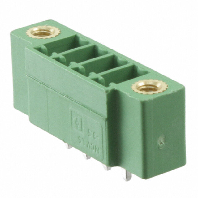
| 描述 | CONN PLUG 5POS INLINE PIN |
| 产品分类 | |
| 品牌 | Amphenol Industrial Operations |
| 数据手册 | |
| 产品图片 | |
| 产品型号 | GTS06G-18-11P |
| rohs | 含铅 / 不符合限制有害物质指令(RoHS)规范要求 |
| 产品系列 | GT,MIL-5015 衍生 |
| 侵入防护 | IP67 - 防尘,防水 |
| 其它名称 | AGTS06G-18-11P |
| 包装 | 散装 |
| 外壳尺寸-插件 | 18-11 |
| 外壳尺寸,MIL | - |
| 外壳材料,镀层 | 铝,镀草绿色镉 |
| 安装类型 | 自由悬挂 |
| 工作温度 | -55°C ~ 125°C |
| 朝向 | N(正常型) |
| 标准包装 | 1 |
| 特性 | 收缩套适配器 |
| 电压-额定 | 500VAC,700VDC |
| 端接 | 焊杯 |
| 紧固类型 | 反向插销锁 |
| 触头镀层 | 银 |
| 触头镀层厚度 | - |
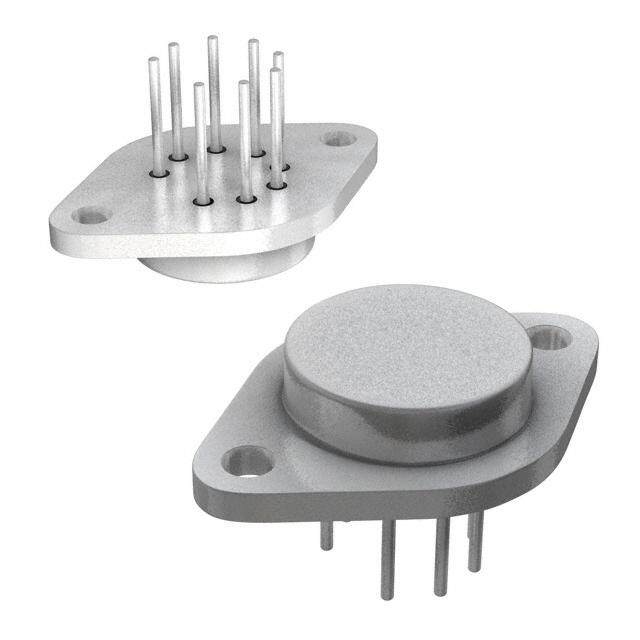
| 连接器类型 | 插头,公引脚 |
| 针脚数 | 5 |
| 额定电流 | - |


PDF Datasheet 数据手册内容提取
Amphenol® ACA-B and GT Series Reverse Bayonet Coupling Connectors AMPHENOL CORPORATION Amphenol Industrial Phone: 888-364-9011 191 Delaware Avenue Sidney, NY 13838-1395 www.amphenol-industrial.com www.amphenol-industrial.com Amphenol®97 Series Connectors are UL recognized and CSA recognized.
For further information on your individual application requirements, contact: Amphenol Corporation Amphenol Industrial Operations 191 Delaware Avenue Sidney, New York 13838-1395 Phone: 888-364-9011 Fax: 520-397-7169 View and download or print Amphenol catalogs on-line at: www.amphenol-industrial.com Amphenol Industrial is a Certified ISO 9001 Manufacturer
Table of Contents Page Amphenol® ACA-B Reverse Bayonet Coupling Connectors General Description ------------------------------------------------------------------- 1 ACA-B Connector Classes -------------------------------------------------------------- 2 ACA 3101F-B inline receptacle ------------------------------------------------------- 3 ACA 3101E-B inline receptacle ------------------------------------------------------- 4 ACA 3101G-B inline receptacle ------------------------------------------------------- 5 ACA 3101R-B inline receptacle ------------------------------------------------------- 6 ACA 3102E-B box mount receptacle for front panel mounting ---------------------------------- 7 ACA 3103F-B wall mount receptacle for rear panel mounting ---------------------------------- 8 ACA 3103E-B wall mount receptacle for rear panel mounting ---------------------------------- 9 ACA 3103G-B wall mount receptacle for rear panel mounting --------------------------------- 10 ACA 3103R-B wall mount receptacle for rear panel mounting --------------------------------- 11 ACA 3106F-B straight plug --------------------------------------------------------- 12 ACA 3106E-B straight plug --------------------------------------------------------- 13 ACA 3106G-B straight plug -------------------------------------------------------- 14 ACA 3106R-B straight plug --------------------------------------------------------- 15 ACA 3107A-B jam nut receptacle ---------------------------------------------------- 16 ACA 3108F-B 90 degree angle plug -------------------------------------------------- 17 ACA 3108E-B 90 degree anlge plug -------------------------------------------------- 18 ACA-B Connectors How to Order --------------------------------------------------------- 78 Amphenol® GT Series Reverse Bayonet Coupling Connectors General Description ------------------------------------------------------------------ 19 GT Connector Classes ---------------------------------------------------------------- 20 GT01A inline receptacle ----------------------------------------------------------- 21 GT01AF/01F inline receptacle ------------------------------------------------------ 22 GT01G inline receptacle ---------------------------------------------------------- 23 GT01R inline receptacle- - - - - - - - - - - - - - - - - - - - - - - - - - - - - - - - - - - - - - - - - - - - - - - - - - - - - - - - - - - 24 GT01RV inline receptacle --------------------------------------------------------- 25 GT02R box mount receptacle for front panel mounting ------------------------------------- 26 GT030 square flange receptacle for rear panel mounting ------------------------------------ 27 GT030A square flange receptacle for rear panel mounting ----------------------------------- 28 GT030AF/030F square flange receptacle for rear panel mounting ----------------------------- 29 GT030G square flange receptacle for rear panel mounting ---------------------------------- 30 GT030R square flange receptacle for rear panel mounting ----------------------------------- 31 GT030RV square flange receptacle for rear panel mounting- - - - - - - - - - - - - - - - - - - - - - - - - - - - - - - - - - 32 GT06A straight plug -------------------------------------------------------------- 33 GT06AF/06F straight plug --------------------------------------------------------- 34 GT06CF straight plug ------------------------------------------------------------ 35 GT06G straight plug ------------------------------------------------------------- 36 GT06AMI/GT06RMI ------------------------------------------------------------- 37 GT06R straight plug ------------------------------------------------------------- 38 GT06RV straight plug ------------------------------------------------------------ 39 GT06SB straight plug ------------------------------------------------------------ 40 GT07R jam nut receptacle --------------------------------------------------------- 41 GT070 jam nut receptacle --------------------------------------------------------- 42 GT08A 90° angle plug ------------------------------------------------------------ 43 GT08AF/08F 90° angle plug -------------------------------------------------------- 44 GT08R 90° angle plug ------------------------------------------------------------ 45 GT05 dummy receptacle ---------------------------------------------------------- 46 GTTB thru-bulkhead receptacles ---------------------------------------------------- 47 GT Connectors How to Order ----------------------------------------------------------- 79 Amphenol ACA-B/GT Reverse Bayonet Insert Arrangements Insert availability --------------------------------------------------------------48-50 Insert alternate positioning --------------------------------------------------------- 51 Solder contacts ----------------------------------------------------------------- 52 Crimp contacts ----------------------------------------------------------------- 53 RADSOK® technology and crimp socket contacts ----------------------------------------- 54 Contact arrangements ----------------------------------------------------------55-77 Amphenol ACA-B/GT Reverse Bayonet Accessories 10-40450, 10-36675, 10-580649 sealing gaskets ----------------------------------------- 80 Receptacle protection caps -------------------------------------------------------- 81 Plug protection caps ------------------------------------------------------------- 82 Rear mounting data - receptacles, sealing plugs, sealing ranges ------------------------------ 83 MS3057-A cable clamp ----------------------------------------------------------- 84 MS3420 bushing --------------------------------------------------------------- 85 MS3057-C style (10-350349) cable clamp ---------------------------------------------- 86 Glands ---------------------------------------------------------------------- 87 GT Amphe-Power Connectors with RADSOK® Technology, Amphe-Power™ Amphe-GTR, Power GT -------------------------------------------------- 88 Special Application GT Connectors: GTC-M Series with metal clips, GT-PC Connectors for high voltage power applications, GT Connectors for the HMI Lighting industry -------------------------------------------- 89 Additional Amphenol Industrial Products for the Rail Industry -------------------------------90, 91
Amphenol ACA-B Connectors ® Amphenol ACA-B Connectors ® with reverse bayonet coupling with reverse bayonet coupling FFeeaattuurreess o of ft hthee A Ammphpehneonlo® lA®C AAC-BA R-Be vReervsee rse Features of the Amphenol® ACA-B Reverse BBaayyoonneett C Coouupplilningg C Cononnencetcotrosr sw iwthit h MIL-DTL- Bayonet Coupling Connectors with MIL-DTL- S5A01E5 A iSn5s0e1rt5 1p ainttseerrnt sp:atterns: 5015 insert patterns: • Quick positive coupling • Quick positive coupling • Audible and tactile indication of full coupling • Audible and tactile indication of full coupling The ACA-B is designed for commercial and Industrial • Waterproof - IP67 rated The ACA-B is designed for commercial and Industrial • Waterproof - IP67 rated environments requiring a rugged bayonet style connec- • No lockwiring required environments requiring a rugged bayonet style connec- • No lockwiring required tor for heavy duty power and signal applications. • High shock and vibration capabilites tor for heavy duty power and signal applications. •• HInisgehr tssh aovcak ilaanbdle v iinb rNaetioonp rceanpeabilites AA ccoommpprreehheennssiivvee sseelleeccttiioonn ooff iinnsseerrtt aarrrraannggeemmeennttss aanndd aacccceess-- •• IAnvsaeirltasb alev ainil abbolteh icnr iNmepo parnedn seolder terminations Assoo crryyo mhhpaarrreddhwweaanrrseei vcceoo snneffiilggeuucrtriaaottniioo nonsfs inaasrreeer tff eeaaarrttauunrreegdde mttooe naatscc ccaoonmmdm maooccddeaasttee- •• ACvoanitlaabctles ainv abiolathb lcer iimn pg oalndd a snodl dseilvr eter rpmlaintiantgions shhoeeraayvv yyh--addruudttwyy,,a ccrooemm cmmoenerfriccgiiaualrl awwtiiiroreen asa nnaddr ceca abfbelelae.t.ured to accommodate • Contacts available in gold and silver plating hAeCaAv-yB-d ius tmy, acnoumfamceturrceiadl iwn iraec caonrdd acnacbele w. ith MIL-DTL-5015 and • Numerous finishes available ACA-B is manufactured in accordance with MIL-DTL-5015 and • Numerous finishes available VAGCA95-B2 3is4 .m Tahneu finascutularetodr sin a arecc moraddaen coef hwiigthh SqAuaEl iAtyS p5o0l1yc5h1l oarnod- • Zinc alloy plating (cadmium free) available VG95234. The insulators are made of high quality polychloro- • Zinc alloy plating (cadmium free) available pVrGen9e5 2m3a4t.e rTiahle a innds uclaanto wrsi tahrseta mnda dteem opf ehriagthu rqeusa olitfy – p5o5l ytoc h+lo1r2o5- • Rugged construction prene material and can withstand temperatures of –55 to +125 • Rugged construction dperegnreee ms aCte. rTiahle a rnudg gceadn swhitehlls itsa nmda tdeem fproemra taulruems inouf m-5 5a ltloo y+ a1n2d5 • Intermateable with existing VG95234 connectors degrees C. The rugged shell is made from aluminum alloy and • Intermateable with existing VG95234 connectors pdleagterede ws iCth. Ta hvea rriuegtyg eodf fsinhieslhl eiss m toa dmee ferot man ayl uamppinliucmat iaolnlo. yC aonnd- • 500 couplings minimum plated with a variety of finishes to meet any application. Con- •• 5U0p0 t oco 5u0p%lin mgso rmei naimmpuamcity with the use of RADSOK® ttpaalcactttsse daa wrreei t hmm aaa ccvhhaiinrnieeedtdy fforroof mmfin iccsoohppeppse etrro aamlllloeoyey t ooarrn ybb rraaapsspss l iacaanntddio ncca.a nnC obbnee- • Usopc tkoe t5 0co%n tmacotrse. aCmonpsauclitt yA wmipthh ethneo lu Isned uosf tRriAalD OSpOeKra®- pptallaacttteesd da rwweii ttmhh aggcoohllddin oeordr ssfriillovvmeerr .c.opper alloy or brass and can be plated stioocnkse fto cr omnotarcet sin. fCoromnasutioltn A omr psheeen Aolm Inpdhuesntorila® l AOmppehrae-- with gold or silver. tPioonwse fro Cr mononree cintofrosr mwaitthio Rn AoDr SseOeK A® mTpehchennoollo® gAym, SphL-e- Common applications include automation, machine tool, robot- P39o1w e(or nClionnen aetc wtowrsw w.aimthp RhAenDoSl-OinKd®u sTtericahl.ncoolmog).y, SL- CiCcoso,mm immnsootnnru aamppeppnlliictcaaattitioioonnn,s s p iinnroccclluueddsees aacuuottonomtmroaalt,ti ioomnn,a, mtmearaicachlh iinhnaee n ttodooloinll,,g rr,oo bbaoonttd-- 391 (online at www.amphenol-industrial.com). ics, instrumentation, process control, material handling, and • Operating temperature range: -55°c to 125°c ticess,t ainnsdt rmumeaesnutaretimone,n pt.rocess control, material handling, and • Operating temperature range: -55°c to 125°c test and measurement. test and measurement. RARAAmvovoaaHHpiiShSllaae bbCCnlloooeelmm ––Inp p CCdlliiuooaasnnnntssrttu iu aPPlltltr rOooddpuuerccatttions. AAmmRR ppoohhHHeenSnSooll Amphenol Industrial Operations. EEUU // 22000022 // 9955 // EECC 1 1 1
ACA-B Connector Classes 25 2
ACA 3101F-B inline receptacle • Receptacle with solid backshell and rear accessory threads • Includes grommet and grommet sleeve M P B N F Q K S L Inches B M N Shell Thread F K L + .016 + .000 P Q S Size Class 2A Min. Min. Max. – .000 – .006 ± .008 ± .008 Max. 10SL .6250-24 UNEF .409 .374 1.969 .717 .717 .110 .811 .992 14S .7500-20 UNEF .520 .374 1.969 .717 .969 .126 1.000 1.173 16S .8750-20 UNEF .638 .374 1.969 .717 1.079 .126 1.126 1.272 16 .8750-20 UNEF .638 .374 2.362 .846 1.079 .126 1.126 1.272 18 1.0000-20 UNEF .756 .374 2.362 .907 1.213 .157 1.248 1.370 20 1.1875-18 UNEF .867 .374 2.362 .907 1.346 .157 1.374 1.488 22 1.1875-18 UNEF .965 .374 2.362 .907 1.472 .157 1.500 1.618 24 1.4375-18 UNEF 1.094 .374 2.560 .907 1.610 .157 1.626 1.756 28 1.4375-18 UNEF 1.228 .374 2.560 .947 1.839 .157 1.874 2.004 32 1.7500-18 UNS 1.488 .433 2.560 .947 2.102 .157 2.126 2.248 36 2.0000-18 UNS 1.780 .465 3.150 .947 2.346 .157 2.386 2.504 Millimeters M N Shell F K L + 0.4 + 0.00 P Q S Size Min. Min. Max. – 0.0 – 0.15 ± 0.2 ± 0.2 Max. 10SL 10.4 9.5 50 18.2 18.2 2.8 20.6 25.2 14S 13.2 9.5 50 18.2 24.6 3.2 25.4 29.8 16S 16.2 9.5 50 18.2 27.4 3.2 28.6 32.3 16 16.2 9.5 60 21.5 27.4 3.2 28.6 32.3 18 19.2 9.5 60 23.0 30.8 4.0 31.7 34.8 20 22.0 9.5 60 23.0 34.2 4.0 34.9 37.8 22 24.5 9.5 60 23.0 37.4 4.0 38.1 41.1 24 27.8 9.5 65 23.0 40.9 4.0 41.3 44.6 28 31.2 9.5 65 24.1 46.7 4.0 47.6 50.9 32 37.8 11.0 65 24.1 53.4 4.0 54.0 57.1 36 45.2 11.8 80 24.1 59.6 4.0 60.6 63.6 All dimensions for reference only. 30 3
ACA 3101E-B inline receptacle • Receptacle with cable clamp and telescopic bushing • Includes grommet and grommet sleeve M P N B KK Q L S LL Inches M N Shell B L + .016 + .000 P Q S KK LL Size Max. Max. – .000 – .006 ± .008 Max. Max. Max. Max. 10SL .256 2.362 .717 .717 .110 .886 .992 .894 4.720 14S .354 2.440 .717 .969 .126 1.161 1.173 1.083 4.720 16S .433 2.756 .717 1.079 .126 1.240 1.272 1.181 4.720 16 .433 2.756 .846 1.079 .126 1.240 1.272 1.181 4.921 18 .559 3.031 .907 1.213 .157 1.358 1.370 1.300 4.921 20 .622 3.031 .907 1.346 .157 1.476 1.488 1.476 4.921 22 .622 3.031 .907 1.472 .157 1.594 1.618 1.476 4.921 24 .843 3.346 .907 1.610 .157 1.752 1.756 1.705 4.921 28 .843 3.346 .947 1.839 .157 1.969 2.004 1.705 4.921 32 1.051 3.346 .947 2.102 .157 2.224 2.248 2.035 4.921 36 1.248 4.134 .947 2.346 .157 2.480 2.504 2.283 5.315 Millimeters M N Shell B L + 0.4 + 0.00 P Q S KK LL Size Max. Max. – 0.0 – 0.15 ± 0.2 Max. Max. Max. Max. 10SL 6.5 60 18.2 18.2 2.8 22.5 25.2 22.7 120 14S 9.0 62 18.2 24.6 3.2 29.5 29.8 27.5 120 16S 11.0 70 18.2 27.4 3.2 31.5 32.3 30.0 120 16 11.0 70 21.5 27.4 3.2 31.5 32.3 30.0 125 18 14.2 77 23.0 30.8 4.0 34.5 34.8 33.0 125 20 15.8 77 23.0 34.2 4.0 37.5 37.8 37.5 125 22 15.8 77 23.0 37.4 4.0 40.5 41.1 37.5 125 24 21.4 85 23.0 40.9 4.0 44.5 44.6 43.3 125 28 21.4 85 24.1 46.7 4.0 50.0 50.9 43.3 125 32 26.7 85 24.1 53.4 4.0 56.5 57.1 51.7 125 36 31.7 105 24.1 59.6 4.0 63.0 63.6 58.0 135 All dimensions for reference only. 31 4
ACA 3101G-B inline receptacle • Receptacle with backshell for heat shrink termination • Does not include grommet and grommet sleeve M P N Z BB JJ KK J Q K S L Inches M N Shell J K L + .016 + .000 P Q S Z BB JJ KK Size ± .008 ± .020 Max. – .000 – .006 ± .008 Max. Max. Min. Max. ± .008 ± .008 10SL .138 .461 1.969 .717 .717 .110 .886 .992 .303 .524 .610 .669 14S .138 .461 1.969 .717 .969 .126 1.161 1.173 .417 .669 .752 .791 16S .138 .461 1.969 .717 1.079 .126 1.240 1.272 .531 .862 .941 .925 16 .138 .453 2.362 .846 1.079 .126 1.240 1.272 .531 .862 .941 .925 18 .138 .453 2.362 .907 1.213 .157 1.358 1.370 .575 .862 .941 1.043 20 .138 .500 2.559 .907 1.346 .157 1.476 1.488 .736 1.031 1.165 1.189 22 .138 .500 2.559 .907 1.472 .157 1.594 1.618 .819 1.031 1.165 1.323 24 .138 .500 2.559 .907 1.610 .157 1.752 1.756 .969 1.358 1.488 1.421 28 .138 .500 2.559 .947 1.839 .157 1.969 2.004 1.062 1.358 1.488 1.630 32 .138 .598 2.756 .947 2.102 .157 2.224 2.248 1.311 1.717 1.882 1.913 36 .138 .598 3.150 .947 2.346 .157 2.480 2.504 1.516 1.717 1.882 2.157 Millimeters M N Shell J K L + 0.4 + 0.00 P Q S Z BB JJ KK Size ± 0.2 ± 0.5 Max. – 0.0 – 0.15 ± 0.2 Max. Max. Min. Max. ± 0.2 ± 0.2 10SL 3.5 11.7 50 18.2 18.2 2.8 22.5 25.2 7.7 13.3 15.5 17.0 14S 3.5 11.7 50 18.2 24.6 3.2 29.5 29.8 10.6 17.0 19.1 20.1 16S 3.5 11.7 50 18.2 27.4 3.2 31.5 32.3 13.5 21.9 23.9 23.5 16 3.5 11.5 60 21.5 27.4 3.2 31.5 32.3 13.5 21.9 23.9 23.5 18 3.5 11.5 60 23.0 30.8 4.0 34.5 34.8 14.6 21.9 23.9 26.5 20 3.5 12.7 65 23.0 34.2 4.0 37.5 37.8 18.7 26.2 29.6 30.2 22 3.5 12.7 65 23.0 37.4 4.0 40.5 41.1 20.8 26.2 29.6 33.6 24 3.5 12.7 65 23.0 40.9 4.0 44.5 44.6 24.6 34.5 37.8 36.1 28 3.5 12.7 65 24.1 46.7 4.0 50.0 50.9 27.0 34.5 37.8 41.4 32 3.5 15.2 70 24.1 53.4 4.0 56.5 57.1 33.3 43.6 47.8 48.6 36 3.5 15.2 80 24.1 59.6 4.0 63.0 63.6 38.5 43.6 47.8 54.8 All dimensions for reference only. 32 5
ACA 3101R-B inline receptacle • Receptacle with short endbell for individual wire sealing • Includes grommet and grommet sleeve M P N KK Q S L Inches M N Shell L + .016 + .000 P Q S KK Size Max. – .000 – .006 ± .008 Max. Max. Max. 10SL 1.890 .717 .717 .110 .886 .992 .787 14S 1.890 .717 .969 .126 1.161 1.173 .945 16S 1.890 .717 1.079 .126 1.240 1.272 1.024 16 2.205 .846 1.079 .126 1.240 1.272 1.024 18 2.244 .907 1.213 .157 1.358 1.370 1.161 20 2.244 .907 1.346 .157 1.476 1.488 1.299 22 2.244 .907 1.472 .157 1.594 1.618 1.417 24 2.244 .907 1.610 .157 1.752 1.756 1.575 28 2.244 .947 1.839 .157 1.969 2.004 1.811 32 2.362 .947 2.102 .157 2.224 2.248 2.028 36 2.362 .947 2.346 .157 2.480 2.504 2.283 Millimeters M N Shell L + 0.4 + 0.00 P Q S KK Size Max. – 0.0 – 0.15 ± 0.2 Max. Max. Max. 10SL 48.0 18.2 18.2 2.8 22.5 25.2 20.0 14S 48.0 18.2 24.6 3.2 29.5 29.8 24.0 16S 48.0 18.2 27.4 3.2 31.5 32.3 26.0 16 56.0 21.5 27.4 3.2 31.5 32.3 26.0 18 57.0 23.0 30.8 4.0 34.5 34.8 29.5 20 57.0 23.0 34.2 4.0 37.5 37.8 33.0 22 57.0 23.0 37.4 4.0 40.5 41.1 36.0 24 57.0 23.0 40.9 4.0 44.5 44.6 40.0 28 57.0 24.1 46.7 4.0 50.0 50.9 46.0 32 60.0 24.1 53.4 4.0 56.5 57.1 51.5 36 60.0 24.1 59.6 4.0 63.0 63.6 58.0 All dimensions for reference only. 33 6
ACA 3A1C0A2 E3-1B02E-B box moubnotx r mecoeupntat crelec efoprt afrcolen tf opra fnreoln mt poaunnetiln mgounting • Receptacle wi•thoRuet cthepretaacdlse fworit hpoanuet lt hmreoaudnsti nfogr panel mounting • Four through •moFuonutirn tgh rhooulegsh omr ooupntitoinnga lh moleetsr ico rt horpetaiodneadl hmoeletrsic threaded holes T T M P M P THRU HOLE THRU HOLE 82º 82º R S R N S N KK KK T T T1 T1 THREAD RTHREAD R L L S S Inches Inches T T M N M N Thru Hole Thru Hole Shell L Shell +.016 L +.00+0.016 P +.000 R P S R +.004 S KK+.004 KK Size ±.012Size –.00±0.012 –.00–6.000 ±.00–8.006 ±.00±4.008 ±.01±2.004 –.00±0.012 Max–. .000 Max. 10SL 1.08710SL .7117.087 .717 .717 .110 .717 .717.110 1.000.717 .1261.000 .626.126 .626 14S 1.08714S .7117.087 .969 .717 .126 .969 .906.126 1.181.906 .1261.181 .756.126 .756 16S 1.08716S .7117.087 1.079 .717 .1261.079 .969.126 1.280.969 .1261.280 .882.126 .882 16 1.33116 .8416.331 1.079 .846 .1261.079 .969.126 1.280.969 .1261.280 .882.126 .882 18 1.33118 .9017.331 1.213 .907 .1571.213 1.063.157 1.3781.063 .1261.378 1.008.126 1.008 20 1.33120 .9017.331 1.346 .907 .1571.346 1.157.157 1.4961.157 .1261.496 1.142.126 1.142 22 1.33122 .9017.331 1.472 .907 .1571.472 1.252.157 1.6141.252 .1261.614 1.268.126 1.268 24 1.33124 .9017.331 1.610 .907 .1571.610 1.374.157 1.7521.374 .1461.752 1.390.146 1.390 28 1.40628 .9417.406 1.839 .947 .1571.839 1.563.157 2.0001.563 .1462.000 1.630.146 1.630 32 1.46932 .9417.469 2.102 .947 .1572.102 1.752.157 2.2441.752 .1692.244 1.882.169 1.882 36 1.46936 .9417.469 2.346 .947 .1572.346 1.937.157 2.5001.937 .1692.500 2.063.169 2.063 Millimeters Millimeters M N M N ThruT Hole T1ThruT Hole T1 Shell L Shell +0.4 L +0.00 +0.4 P +0.00 R P S R +0.1 S Metric+0.1 KK Metric KK Size ±0.3 Size –0.0 ±0.3 –0.15 –0.0 ±0.2 –0.15 ±0.1 ±0.2 ±0.3 ±0.1 –0.0±0.3 Thread–0.0 Max.Thread Max. 10SL 27.610SL 18.227.6 18.2 18.22.8 18.2 18.2 2.8 25.4 18.2 3.2 25.4 M43.2 15.9 M4 15.9 14S 27.614S 18.227.6 24.6 18.23.2 24.6 23.0 3.2 30.0 23.0 3.2 30.0 M43.2 19.2 M4 19.2 16S 27.616S 18.227.6 27.4 18.23.2 27.4 24.6 3.2 32.5 24.6 3.2 32.5 M43.2 22.4 M4 22.4 16 33.816 21.533.8 27.4 21.53.2 27.4 24.6 3.2 32.5 24.6 3.2 32.5 M43.2 22.4 M4 22.4 18 33.818 23.033.8 30.8 23.04.0 30.8 27.0 4.0 35.0 27.0 3.2 35.0 M43.2 25.6 M4 25.6 20 33.820 23.033.8 34.2 23.04.0 34.2 29.4 4.0 38.0 29.4 3.2 38.0 M43.2 29.0 M4 29.0 22 33.822 23.033.8 37.4 23.04.0 37.4 31.8 4.0 41.0 31.8 3.2 41.0 M43.2 32.2 M4 32.2 24 33.824 23.033.8 40.9 23.04.0 40.9 34.9 4.0 44.5 34.9 3.7 44.5 M43.7 35.3 M4 35.3 28 35.728 24.135.7 46.7 24.14.0 46.7 39.7 4.0 50.8 39.7 3.7 50.8 M53.7 41.4 M5 41.4 32 37.332 24.137.3 53.4 24.14.0 53.4 44.5 4.0 57.0 44.5 4.3 57.0 M54.3 47.8 M5 47.8 36 37.336 24.137.3 59.6 24.14.0 59.6 49.2 4.0 63.5 49.2 4.3 63.5 M54.3 52.4 M5 52.4 All dimensions for reAfellr ednimcee nosniloyn.s for reference only. 34 34 7
ACA 3103F-B wall mounting receptacle for rear panel mounting • Receptacle with backshell and rear accessory threads • Includes wire sealing grommet and grommet sleeve for individual wires • Four through mounting holes or optional metric threaded holes T M P B THRU HOLE R S N F T1 THREAD K R S L Inches T B M N Thru Hole Shell Thread F K L +.016 +.000 P R S + .004 Size Class 2A Min. Min. Max. –.000 –.006 ± .008 ± .004 ± .012 – .000 10SL .6250-24 UNEF .409 .374 1.969 .717 .717 .110 .717 1.000 .126 14S .7500-20 UNEF .520 .374 1.969 .717 .969 .126 .906 1.181 .126 16S .8750-20 UNEF .638 .374 1.969 .717 1.079 .126 .969 1.280 .126 16 .8750-20 UNEF .638 .374 2.362 .846 1.079 .126 .969 1.280 .126 18 1.0000-20 UNEF .756 .374 2.362 .907 1.213 .157 1.063 1.378 .126 20 1.1875-18 UNEF .867 .374 2.362 .907 1.346 .157 1.157 1.496 .126 22 1.1875-18 UNEF .965 .374 2.362 .907 1.472 .157 1.252 1.614 .126 24 1.4375-18 UNEF 1.094 .374 2.560 .907 1.610 .157 1.374 1.752 .146 28 1.4375-18 UNEF 1.228 .374 2.560 .947 1.839 .157 1.563 2.000 .146 32 1.7500-18 UNS 1.488 .433 2.560 .947 2.102 .157 1.752 2.244 .169 36 2.0000-18 UNS 1.780 .465 3.150 .947 2.346 .157 1.937 2.500 .169 Millimeters T M N Thru Hole T1 Shell F K L + 0.4 + 0.00 P R S + 0.1 Metric Size Min. Min. Max. – 0.0 – 0.15 ± 0.2 ± 0.1 ± 0.3 – 0.0 Thread 10SL 10.4 9.5 50 18.2 18.2 2.8 18.2 25.4 3.2 M4 14S 13.2 9.5 50 18.2 24.6 3.2 23.0 30.0 3.2 M4 16S 16.2 9.5 50 18.2 27.4 3.2 24.6 32.5 3.2 M4 16 16.2 9.5 60 21.5 27.4 3.2 24.6 32.5 3.2 M4 18 19.2 9.5 60 23.0 30.8 4.0 27.0 35.0 3.2 M4 20 22.0 9.5 60 23.0 34.2 4.0 29.4 38.0 3.2 M4 22 24.5 9.5 60 23.0 37.4 4.0 31.8 41.0 3.2 M4 24 27.8 9.5 65 23.0 40.9 4.0 34.9 44.5 3.7 M4 28 31.2 9.5 65 24.1 46.7 4.0 39.7 50.8 3.7 M5 32 37.8 11.0 65 24.1 53.4 4.0 44.5 57.0 4.3 M5 36 45.2 11.8 80 24.1 59.6 4.0 49.2 63.5 4.3 M5 All dimensions for reference only. 35 8
ACA 3103E-B wall mount receptacle for rear panel mounting • Receptacle with cable clamp and telescopic bushing • Includes grommet and grommet sleeve • Four through mounting holes or optional metric threaded holes T M P THRU HOLE R S A Z KK T1 THREAD R L S LL Inches T M N Thru Hole Shell L +.016 + .000 P R S + .004 Z KK LL Size Max. –.000 – .006 ± .008 ± .004 ± .012 – .000 Max. Max. Max. 10SL 2.362 .717 .717 .110 .717 1.000 .126 .256 .894 4.720 14S 2.440 .717 .969 .126 .906 1.181 .126 .354 1.083 4.720 16S 2.756 .717 1.079 .126 .969 1.280 .126 .433 1.181 4.720 16 2.756 .846 1.079 .126 .969 1.280 .126 .433 1.181 4.921 18 3.031 .907 1.213 .157 1.063 1.378 .126 .559 1.300 4.921 20 3.031 .907 1.346 .157 1.157 1.496 .126 .622 1.476 4.921 22 3.031 .907 1.472 .157 1.252 1.614 .126 .622 1.476 4.921 24 3.346 .907 1.610 .157 1.374 1.752 .146 .843 1.705 4.921 28 3.346 .947 1.839 .157 1.563 2.000 .146 .843 1.705 4.921 32 3.346 .947 2.102 .157 1.752 2.244 .169 1.051 2.035 4.921 36 4.134 .947 2.346 .157 1.937 2.500 .169 1.248 2.283 5.315 Millimeters T M N Thru Hole T1 Shell L + 0.4 + 0.00 P R S + 0.1 Metric Z KK LL Size Max. – 0.0 – 0.15 ± 0.2 ± 0.1 ± 0.3 – 0.0 Thread Max. Max. Max. 10SL 60 18.2 18.2 2.8 18.2 25.4 3.2 M4 6.5 22.7 120 14S 62 18.2 24.6 3.2 23.0 30.0 3.2 M4 9.0 27.5 120 16S 70 18.2 27.4 3.2 24.6 32.5 3.2 M4 11.0 30.0 120 16 70 21.5 27.4 3.2 24.6 32.5 3.2 M4 11.0 30.0 125 18 77 23.0 30.8 4.0 27.0 35.0 3.2 M4 14.2 33.0 125 20 77 23.0 34.2 4.0 29.4 38.0 3.2 M4 15.8 37.5 125 22 77 23.0 37.4 4.0 31.8 41.0 3.2 M4 15.8 37.5 125 24 85 23.0 40.9 4.0 34.9 44.5 3.7 M4 21.4 43.3 125 28 85 24.1 46.7 4.0 39.7 50.8 3.7 M5 21.4 43.3 125 32 85 24.1 53.4 4.0 44.5 57.0 4.3 M5 26.7 51.7 125 36 105 24.1 59.6 4.0 49.2 63.5 4.3 M5 31.7 58.0 135 All dimensions for reference only. 36 9
ACA 3103G-B wall mount receptacle for rear panel mounting • Receptacle with endbell for heat shrink termination • Does not include grommet and grommet sleeve • Four through mounting holes or optional metric threaded holes T M P THRU HOLE R S N Z BB JJ KK T1 THREAD J R K S L Inches T M N Thru Hole Shell J K L + .016 + .000 P R S + .004 Z BB JJ KK Size ± .008 ± .020 Max. – .000 – .006 ± .008 ± .004 ± .012 – .000 Min. Max. ± .008 ± .008 10SL .138 .461 1.969 .717 .717 .110 .717 1.000 .126 .303 .524 .610 .669 14S .138 .461 1.969 .717 .969 .126 .906 1.181 .126 .417 .669 .752 .791 16S .138 .461 1.969 .717 1.079 .126 .969 1.280 .126 .531 .862 .941 .925 16 .138 .453 2.362 .846 1.079 .126 .969 1.280 .126 .531 .862 .941 .925 18 .138 .453 2.362 .907 1.213 .157 1.063 1.378 .126 .575 .862 .941 1.043 20 .138 .500 2.559 .907 1.346 .157 1.157 1.496 .126 .736 1.031 1.165 1.189 22 .138 .500 2.559 .907 1.472 .157 1.252 1.614 .126 .819 1.031 1.165 1.323 24 .138 .500 2.559 .907 1.610 .157 1.374 1.752 .146 .969 1.358 1.488 1.421 28 .138 .500 2.559 .947 1.839 .157 1.563 2.000 .146 1.062 1.358 1.488 1.630 32 .138 .598 2.756 .947 2.102 .157 1.752 2.244 .169 1.311 1.717 1.882 1.913 36 .138 .598 3.150 .947 2.346 .157 1.937 2.500 .169 1.516 1.717 1.882 2.157 Millimeters T M N Thru Hole T1 Shell J K L + 0.4 + 0.00 P R S + 0.1 Metric Z BB JJ KK Size ± 0.2 ± 0.5 Max. – 0.0 – 0.15 ± 0.2 ± 0.1 ± 0.3 – 0.0 Thread Min. Max. ± 0.2 ± 0.2 10SL 3.5 11.7 50 18.2 18.2 2.8 18.2 25.4 3.2 M4 7.7 13.3 15.5 17.0 14S 3.5 11.7 50 18.2 24.6 3.2 23.0 30.0 3.2 M4 10.6 17.0 19.1 20.1 16S 3.5 11.7 50 18.2 27.4 3.2 24.6 32.5 3.2 M4 13.5 21.9 23.9 23.5 16 3.5 11.5 60 21.5 27.4 3.2 24.6 32.5 3.2 M4 13.5 21.9 23.9 23.5 18 3.5 11.5 60 23.0 30.8 4.0 27.0 35.0 3.2 M4 14.6 21.9 23.9 26.5 20 3.5 12.7 65 23.0 34.2 4.0 29.4 38.0 3.2 M4 18.7 26.2 29.6 30.2 22 3.5 12.7 65 23.0 37.4 4.0 31.8 41.0 3.2 M4 20.8 26.2 29.6 33.6 24 3.5 12.7 65 23.0 40.9 4.0 34.9 44.5 3.7 M4 24.6 34.5 37.8 36.1 28 3.5 12.7 65 24.1 46.7 4.0 39.7 50.8 3.7 M5 27.0 34.5 37.8 41.4 32 3.5 15.2 70 24.1 53.4 4.0 44.5 57.0 4.3 M5 33.3 43.6 47.8 48.6 36 3.5 15.2 80 24.1 59.6 4.0 49.2 63.5 4.3 M5 38.5 43.6 47.8 54.8 All dimensions for reference only. 37 10
ACA 3103R-B wall mount receptacle for rear panel mounting • Receptacle with short endbell for individual wire sealing • Includes grommet and grommet sleeve • Four through mounting holes or optional metric threaded holes T M P THRU HOLE R S N KK T1 R THREAD S L Inches T M N Thru Hole Shell L + .016 + .000 P R S + .004 KK Size Max. – .000 – .006 ± .008 ± .004 ± .012 – .000 Max. 10SL 1.890 .717 .717 .110 .717 1.000 .126 .787 14S 1.890 .717 .969 .126 .906 1.181 .126 .945 16S 1.890 .717 1.079 .126 .969 1.280 .126 1.024 16 2.205 .846 1.079 .126 .969 1.280 .126 1.024 18 2.244 .907 1.213 .157 1.063 1.378 .126 1.161 20 2.244 .907 1.346 .157 1.157 1.496 .126 1.299 22 2.244 .907 1.472 .157 1.252 1.614 .126 1.417 24 2.244 .907 1.610 .157 1.374 1.752 .146 1.575 28 2.244 .947 1.839 .157 1.563 2.000 .146 1.811 32 2.362 .947 2.102 .157 1.752 2.244 .169 2.028 36 2.362 .947 2.346 .157 1.937 2.500 .169 2.283 Millimeters T M N Thru Hole T1 Shell L + 0.4 + 0.00 P R S + 0.1 Metric KK Size Max. – 0.0 – 0.15 ± 0.2 ± 0.1 ± 0.3 – 0.0 Thread Max. 10SL 48.0 18.2 18.2 2.8 18.2 25.4 3.2 M4 20.0 14S 48.0 18.2 24.6 3.2 23.0 30.0 3.2 M4 24.0 16S 48.0 18.2 27.4 3.2 24.6 32.5 3.2 M4 26.0 16 56.0 21.5 27.4 3.2 24.6 32.5 3.2 M4 26.0 18 57.0 23.0 30.8 4.0 27.0 35.0 3.2 M4 29.5 20 57.0 23.0 34.2 4.0 29.4 38.0 3.2 M4 33.0 22 57.0 23.0 37.4 4.0 31.8 41.0 3.2 M4 36.0 24 57.0 23.0 40.9 4.0 34.9 44.5 3.7 M4 40.0 28 57.0 24.1 46.7 4.0 39.7 50.8 3.7 M5 46.0 32 60.0 24.1 53.4 4.0 44.5 57.0 4.3 M5 51.5 36 60.0 24.1 59.6 4.0 49.2 63.5 4.3 M5 58.0 All dimensions for reference only. 38 11
ACA 3106F-B straight plug • Plug with backshell and rear accessory threads • Includes grommet and grommet sleeve B F K Q L Inches B Shell Thread F K L Q Size Class 2A Min. Min. Max. Max. 10SL .6250-24UNEF .409 .374 1.969 .898 14S .7500-20UNEF .520 .374 1.969 1.150 16S .8750-20UNEF .638 .374 1.969 1.260 16 .8750-20UNEF .638 .374 2.362 1.260 18 1.0000-20UNEF .756 .374 2.362 1.437 20 1.1875-18UNEF .867 .374 2.362 1.571 22 1.1875-18UNEF .965 .374 2.362 1.697 24 1.4375-18UNEF 1.094 .374 2.560 1.835 28 1.4375-18UNEF 1.228 .374 2.560 2.102 32 1.7500-18UNS 1.488 .433 2.560 2.366 36 2.0000-18UNS 1.780 .465 3.150 2.610 Millimeters Shell F K L Q Size Min. Min. Max. Max. 10SL 10.4 9.5 50 22.8 14S 13.2 9.5 50 29.2 16S 16.2 9.5 50 32.0 16 16.2 9.5 60 32.0 18 19.2 9.5 60 36.5 20 22.0 9.5 60 39.9 22 24.5 9.5 60 43.1 24 27.8 9.5 65 46.6 28 31.2 9.5 65 53.4 32 37.8 11.0 65 60.1 36 45.2 11.8 80 66.3 All dimensions for reference only. 39 12
ACA 3106E-B straight plug • Plug with cable clamp and telescopic bushing • Includes grommet and grommet sleeve Z KK L Q LL Inches Shell L Q Z KK LL Size Max. Max. Max. Max. Max. 10SL 2.165 .898 .256 .894 4.528 14S 2.362 1.150 .354 1.083 4.528 16S 2.362 1.260 .433 1.181 4.528 16 2.756 1.260 .433 1.181 4.724 18 2.756 1.437 .559 1.268 4.724 20 2.953 1.571 .622 1.476 4.724 22 2.953 1.697 .622 1.476 4.724 24 3.543 1.835 .843 1.705 4.724 28 3.543 2.102 .843 1.705 4.724 32 3.543 2.366 1.051 2.035 4.724 36 3.937 2.610 1.248 2.283 5.118 Millimeters Shell L Q Z KK LL Size Max. Max. Max. Max. Max. 10SL 55 22.8 6.5 22.7 115 14S 60 29.2 9.0 27.5 115 16S 60 32.0 11.0 30.0 115 16 70 32.0 11.0 30.0 120 18 70 36.5 14.2 32.2 120 20 75 39.9 15.8 37.5 120 22 75 43.1 15.8 37.5 120 24 90 46.6 21.4 43.3 120 28 90 53.4 21.4 43.3 120 32 90 60.1 26.7 51.7 120 36 100 66.3 31.7 58.0 130 All dimensions for reference only. 40 13
ACA 3106G-B straight plug • Plug with backshell for heat shrink termination • Does not include grommet and grommet sleeve Z BB JJ KK J K Q L Inches Shell J K L Q Z BB JJ KK Size ± .008 ± .020 Max. Max. Min. Max. ± .008 ± .008 10SL .138 .461 1.969 .898 .303 .524 .610 .669 14S .138 .461 1.969 1.150 .417 .669 .752 .791 16S .138 .461 1.969 1.260 .531 .862 .941 .925 16 .138 .453 2.362 1.260 .531 .862 .941 .925 18 .138 .453 2.362 1.437 .575 .862 .941 1.043 20 .138 .500 2.559 1.571 .736 1.031 1.165 1.189 22 .138 .500 2.559 1.697 .819 1.031 1.165 1.323 24 .138 .500 2.559 1.835 .969 1.358 1.488 1.421 28 .138 .500 2.559 2.102 1.063 1.358 1.488 1.630 32 .138 .598 2.756 2.366 1.311 1.717 1.882 1.913 36 .138 .598 3.150 2.610 1.516 1.717 1.882 2.157 Millimeters Shell J K L Q Z BB JJ KK Size ± 0.2 ± 0.5 Max. Max. Min. Max. ± 0.2 ± 0.2 10SL 3.5 11.7 50 22.8 7.7 13.3 15.5 17.0 14S 3.5 11.7 50 29.2 10.6 17.0 19.1 20.1 16S 3.5 11.7 50 32.0 13.5 21.9 23.9 23.5 16 3.5 11.5 60 32.0 13.5 21.9 23.9 23.5 18 3.5 11.5 60 36.5 14.6 21.9 23.9 26.5 20 3.5 12.7 65 39.9 18.7 26.2 29.6 30.2 22 3.5 12.7 65 43.1 20.8 26.2 29.6 33.6 24 3.5 12.7 65 46.6 24.6 34.5 37.8 36.1 28 3.5 12.7 65 53.4 27.0 34.5 37.8 41.4 32 3.5 15.2 70 60.1 33.3 43.6 47.8 48.6 36 3.5 15.2 80 66.3 38.5 43.6 47.8 54.8 All dimensions for reference only. 41 14
ACA 3106R-B straight plug • Plug with short endbell for individual wire sealing • Includes grommet and grommet sleeve KK Q L Inches Shell L Q KK Size Max. Max. Max. 10SL 1.417 .898 .787 14S 1.437 1.150 .945 16S 1.437 1.260 1.024 16 1.929 1.260 1.024 18 1.929 1.437 1.161 20 1.969 1.571 1.299 22 1.969 1.697 1.417 24 2.008 1.835 1.543 28 2.008 2.102 1.811 32 2.087 2.366 2.028 36 2.106 2.610 2.283 Millimeters Shell L Q KK Size Max. Max. Max. 10SL 36.0 22.8 20.0 14S 36.5 29.2 24.0 16S 36.5 32.0 26.0 16 49.0 32.0 26.0 18 49.0 36.5 29.5 20 50.0 39.9 33.0 22 50.0 43.1 36.0 24 51.0 46.6 40.0 28 51.0 53.4 46.0 32 53.0 60.1 51.5 36 53.5 66.3 58.0 All dimensions for reference only. 42 15
ACA 3107A-B jam nut receptacle • For rear panel single hole mounting • Panel seal O-ring included • Environment proof S M G J P G S N B O-Ring R Inches J B N Wall Thickness Shell Thread G M + .000 P R S Size Class 2A ± .012 Min. Max. ± .012 – .006 ± .007 ± .016 ± .012 10SL .8750-20 UNEF .441 .094 .205 .965 .717 .157 1.062 1.252 14S 1.1250-18 UNEF .575 .094 .295 1.055 .969 .189 1.312 1.626 16S 1.2500-18 UNEF .618 .094 .295 1.055 1.079 .189 1.500 1.748 16 1.2500-18 UNEF .618 .094 .295 1.264 1.079 .189 1.500 1.748 18 1.3750-18 UNEF .661 .094 .354 1.327 1.213 .189 1.562 1.875 20 1.5000-18 UNEF .709 .094 .358 1.327 1.346 .189 1.750 2.000 22 1.6250-18 UNEF .795 .094 .358 1.327 1.472 .189 2.000 2.134 24 1.7500-18 UNEF .795 .094 .358 1.327 1.610 .189 2.000 2.252 28 2.0000-18 UNS .886 .094 .394 1.386 1.839 .220 2.188 2.500 32 2.2500-16 UN .972 .094 .394 1.386 2.102 .220 2.438 2.748 36 2.5000-16 UN 1.059 .094 .327 1.386 2.346 .220 2.812 3.000 Millimeters J N Wall Thickness Shell G M + 0.00 P R S Size ± 0.3 Min. Max. ± 0.3 – 0.15 ± 0.2 ± 0.4 ± 0.3 10SL 11.2 2.4 5.2 24.5 18.2 4.0 27 31.8 14S 14.6 2.4 7.5 26.8 24.6 4.8 33 41.3 16S 15.7 2.4 7.5 26.8 27.4 4.8 38 44.4 16 15.7 2.4 7.5 32.1 27.4 4.8 38 44.4 18 16.8 2.4 9.0 33.7 30.8 4.8 40 47.6 20 18.0 2.4 9.1 33.7 34.2 4.8 44 50.8 22 20.2 2.4 9.1 33.7 37.4 4.8 51 54.2 24 20.2 2.4 9.1 33.7 40.9 4.8 51 57.2 28 22.5 2.4 10.0 35.2 46.7 5.6 56 63.5 32 24.7 2.4 10.0 35.2 53.4 5.6 62 69.8 36 26.9 2.4 8.3 35.2 59.6 5.6 71 76.2 All dimensions for reference only. 43 16
ACA 3108F-B 90° angle plug • 90° plug for angled attachment to panels with rear accessory threads • Includes grommet and grommet sleeve Q L K J B F Inches B Shell Thread F J K L Q Size Class 2A Max. Min. Max. Max. Max. 10SL .6250-24UNEF .337 .370 1.181 1.772 .898 14S .7500-20UNEF .462 .370 1.181 1.850 1.150 16S .8750-20UNEF .587 .370 1.181 1.890 1.299 16 .8750-20UNEF .587 .370 1.181 2.244 1.299 18 1.0000-20UNEF .685 .370 1.378 2.283 1.437 20 1.1875-18UNEF .810 .370 1.378 2.402 1.571 22 1.1875-18UNEF .915 .370 1.378 2.402 1.697 24 1.4375-18UNEF 1.025 .370 1.575 2.598 1.835 28 1.4375-18UNEF 1.139 .370 1.575 2.598 2.102 32 1.7500-18UNS 1.447 .433 1.772 2.835 2.366 36 2.0000-18UNS 1.687 .496 1.969 2.953 2.610 Millimeters Shell F J K L Q Size Max. Min. Max. Max. Max. 10SL 8.5 9.4 30 45 22.8 14S 11.7 9.4 30 47 29.2 16S 14.9 9.4 30 48 33.0 16 14.9 9.4 30 57 33.0 18 17.4 9.4 35 58 36.5 20 20.5 9.4 35 61 39.9 22 23.2 9.4 35 61 43.1 24 26.0 9.4 40 66 46.6 28 28.9 9.4 40 66 53.4 32 36.7 11.0 45 72 60.1 36 42.8 12.6 50 75 66.3 All dimensions for reference only. 44 17
ACA 3108E-B 90° angle plug • 90° plug for angled attachment to panels with cable clamp and telescopic bushing • Includes grommet and grommet sleeve Q L K LL Z KK Inches Shell K L Q Z KK LL Size Max. Max. Max. Max. Max. Max. 10SL 1.654 1.772 .898 .220 .894 3.937 14S 1.654 1.850 1.150 .312 1.083 3.937 16S 1.772 1.890 1.299 .437 1.181 3.937 16 1.772 2.244 1.299 .437 1.181 3.937 18 2.087 2.283 1.437 .562 1.299 3.937 20 2.087 2.402 1.571 .625 1.476 3.937 22 2.087 2.402 1.697 .625 1.476 3.937 24 2.283 2.598 1.835 .750 1.705 3.937 28 2.283 2.598 2.102 .750 1.705 3.937 32 2.598 2.835 2.366 .937 2.061 4.331 36 2.717 2.953 2.610 1.250 2.283 4.331 Millimeters Shell K L Q Z KK LL Size Max. Max. Max. Max. Max. Max. 10SL 42 45 22.8 5.58 22.7 100 14S 42 47 29.2 7.92 27.5 100 16S 45 48 33.0 11.09 30.0 100 16 45 57 33.0 11.09 30.0 100 18 53 58 36.5 14.27 33.0 100 20 53 61 39.9 15.87 37.5 100 22 53 61 43.1 15.87 37.5 100 24 58 66 46.6 19.05 43.3 100 28 58 66 53.4 19.05 43.3 100 32 66 72 60.1 23.79 51.7 110 36 69 75 66.3 31.75 58.0 110 All dimensions for reference only. 45 18
Amphenol GT Connectors ® with reverse bayonet coupling Designed originally for use by the military, the heavy duty GT connector has become widely used in commercial, geophysical, aerospace, ground support and shipboard applications. It is the preferred connector for mass transit. Variety of Shell Styles are Available Amphenol® GT reverse bayonet coupling connectors with SAE AS50151 insert patterns features: Wall Mount Receptacle • Quick positive coupling • Audible, tactile and visual indication of full coupling • Waterproof – IP67 rated • No lockwiring required • High shock and vibration capabilities • Inserts available in Neoprene and Viton* materials • Low smoke/flame retardant inserts also available Inline Receptacle • Operating temperature range: With Neoprene inserts: –55°C to +125°C With Viton** inserts: –50°C to +200°C With low smoke/flame retardant inserts: –55°C to +125°C • Available in both crimp and solder terminations • Contacts available in gold and silver plating • Numerous commercial finishes available • Zinc alloy plating (cadmium free) available Straight Plug • Rugged construction; aluminum or stainless steel components • Available with resilient cover coupling for added damage protection and increased gripping surface • Intermateable with existing VG95234 connectors • 2000 couplings minimum • UL recognized • Up to 50% more ampacity with the use of RADSOK® technology (see page 54) Jam Nut Receptacle Amphenol’s special offerings of GT Series connectors (see end of catalog) include: GT Amphe-Power® Connectors with RADSOK® technology, the GTC-M Series with metal clip in- serts and GT-PC Series for high voltage power applica tions. There is also information on other Amphenol Industrial Prod- ucts for the Rail Industry at the end of this catalog. NOTE: For further information on your individual application require- The connector products in this brochure were formerly known as ments, contact: Bendix® products. These products are now manufactured and sold Amphenol Corporation under the Amphenol® brand name. The name “Amphenol” will replace the name “Bendix” on products and literature in the future. Amphenol Industrial Operations 191 Delaware Avenue Sidney, New York 13838-1395 Phone: 888-364-9011 Fax: 520-397-7169 www.amphenol-industrial.com **For availability of Viton inserts consult Amphenol, Sidney, NY. Viton is a registered trademark of Dupont/Dow Corning. 19
GT Connector Classes 29 20
GT01A inline receptacle • Includes backshell for accessory attachment • Without wire sealing grommet and cable clamp • Non-environment proof M P B N F Q K S L Inches B M N Shell Thread F K L + .016 + .000 P Q S Size Class 2A Min. Min. Max. – .000 – .006 ± .008 ± .008 Max. 10SL .6250-24 UNEF .409 .374 1.969 .717 .717 .110 .811 .992 14S .7500-20 UNEF .520 .374 1.969 .717 .969 .126 1.000 1.173 16S .8750-20 UNEF .638 .374 1.969 .717 1.079 .126 1.126 1.272 16 .8750-20 UNEF .638 .374 2.362 .846 1.079 .126 1.126 1.272 18 1.0000-20 UNEF .756 .374 2.362 .907 1.213 .157 1.248 1.370 20 1.1875-18 UNEF .867 .374 2.362 .907 1.346 .157 1.374 1.488 22 1.1875-18 UNEF .965 .374 2.362 .907 1.472 .157 1.500 1.618 24 1.4375-18 UNEF 1.094 .374 2.560 .907 1.610 .157 1.626 1.756 28 1.4375-18 UNEF 1.228 .374 2.560 .947 1.839 .157 1.874 2.004 32 1.7500-18 UNS 1.488 .433 2.560 .947 2.102 .157 2.126 2.248 36 2.0000-18 UNS 1.780 .465 3.150 .947 2.346 .157 2.386 2.504 40 2.2500-16 UN 2.016 .465 3.150 .947 2.579 .157 2.618 2.756 Millimeters M N Shell F K L + 0.4 + 0.00 P Q S Size Min. Min. Max. – 0.0 – 0.15 ± 0.2 ± 0.2 Max. 10SL 10.4 9.5 50 18.2 18.2 2.8 20.6 25.2 14S 13.2 9.5 50 18.2 24.6 3.2 25.4 29.8 16S 16.2 9.5 50 18.2 27.4 3.2 28.6 32.3 16 16.2 9.5 60 21.5 27.4 3.2 28.6 32.3 18 19.2 9.5 60 23.0 30.8 4.0 31.7 34.8 20 22.0 9.5 60 23.0 34.2 4.0 34.9 37.8 22 24.5 9.5 60 23.0 37.4 4.0 38.1 41.1 24 27.8 9.5 65 23.0 40.9 4.0 41.3 44.6 28 31.2 9.5 65 24.1 46.7 4.0 47.6 50.9 32 37.8 11.0 65 24.1 53.4 4.0 54.0 57.1 36 45.2 11.8 80 24.1 59.6 4.0 60.6 63.6 40 51.2 11.8 80 24.1 65.5 4.0 66.5 70.0 All dimensions for reference only. 37 21
GT01AF/01F inline receptacle GT01AF GT01F • With cable clamp • With wire sealing grommet and cable clamp • Wire sealing grommet not included • For use with individual wires • Non-environment proof • Environment proof N Z KK Q M P S L LL Inches M N Shell L + .016 + .000 P Q S Z KK LL Size Max. – .000 – .006 ± .008 ± .008 Max. Nominal Max. Max. 10SL 2.362 .717 .717 .110 .811 .992 .220 .894 4.720 14S 2.440 .717 .969 .126 1.000 1.173 .312 1.083 4.720 16S 2.756 .717 1.079 .126 1.126 1.272 .437 1.181 4.720 16 2.756 .846 1.079 .126 1.126 1.272 .437 1.181 4.921 18 3.031 .907 1.213 .157 1.248 1.370 .562 1.300 4.921 20 3.031 .907 1.346 .157 1.374 1.488 .625 1.476 4.921 22 3.031 .907 1.472 .157 1.500 1.618 .625 1.476 4.921 24 3.346 .907 1.610 .157 1.626 1.756 .750 1.705 4.921 28 3.346 .947 1.839 .157 1.874 2.004 .750 1.705 4.921 32 3.346 .947 2.102 .157 2.126 2.248 .937 2.035 4.921 36 4.134 .947 2.346 .157 2.386 2.504 1.250 2.283 5.315 40 5.118 .947 2.579 .157 2.618 2.756 1.375 2.579 5.709 Millimeters M N Shell L + 0.4 + 0.00 P Q S Z KK LL Size Max. – 0.0 – 0.15 ± 0.2 ± 0.2 Max. Nominal Max. Max. 10SL 60 18.2 18.2 2.8 20.6 25.2 5.58 22.7 120 14S 62 18.2 24.6 3.2 25.4 29.8 7.92 27.5 120 16S 70 18.2 27.4 3.2 28.6 32.3 11.09 30.0 120 16 70 21.5 27.4 3.2 28.6 32.3 11.09 30.0 125 18 77 23.0 30.8 4.0 31.7 34.8 14.27 33.0 125 20 77 23.0 34.2 4.0 34.9 37.8 15.87 37.5 125 22 77 23.0 37.4 4.0 38.1 41.1 15.87 37.5 125 24 85 23.0 40.9 4.0 41.3 44.6 19.05 43.3 125 28 85 24.1 46.7 4.0 47.6 50.9 19.05 43.3 125 32 85 24.1 53.4 4.0 54.0 57.1 23.79 51.7 125 36 105 24.1 59.6 4.0 60.6 63.6 31.75 58.0 135 40 130 24.1 65.5 4.0 66.5 70.0 34.92 65.5 145 All dimensions for reference only. 38 22
GT01G inline receptacle • Includes wire sealing grommet • For use with heat-shrink tubing • Environment proof M P N Z BB JJ KK Q J K S L Inches M N Shell J K L + .016 + .000 P Q S Z BB JJ KK Size ± .008 ± .020 Max. – .000 – .006 ± .008 ± .008 Max. Min. Max. ± .008 ± .008 10SL .138 .461 1.969 .717 .717 .110 .811 .992 .303 .524 .610 .669 14S .138 .461 1.969 .717 .969 .126 1.000 1.173 .417 .669 .752 .791 16S .138 .461 1.969 .717 1.079 .126 1.126 1.272 .531 .862 .941 .925 16 .138 .453 2.362 .846 1.079 .126 1.126 1.272 .531 .862 .941 .925 18 .138 .453 2.362 .907 1.213 .157 1.248 1.370 .575 .862 .941 1.043 20 .138 .500 2.559 .907 1.346 .157 1.374 1.488 .736 1.031 1.165 1.189 22 .138 .500 2.559 .907 1.472 .157 1.500 1.618 .819 1.031 1.165 1.323 24 .138 .500 2.559 .907 1.610 .157 1.626 1.756 .969 1.358 1.488 1.421 28 .138 .500 2.559 .947 1.839 .157 1.874 2.004 1.063 1.358 1.488 1.630 32 .138 .598 2.756 .947 2.102 .157 2.126 2.248 1.311 1.717 1.882 1.913 36 .138 .598 3.150 .947 2.346 .157 2.386 2.504 1.516 1.717 1.882 2.157 40 .138 .610 3.150 .947 2.579 1.57 2.618 2.756 1.898 2.071 2.276 2.402 Millimeters M N Shell J K L + 0.4 + 0.00 P Q S Z B JJ KK Size ± 0.2 ± 0.5 Max. – 0.0 – 0.15 ± 0.2 ± 0.2 Max. Min. Max. ± 0.2 ± 0.2 10SL 3.5 11.7 50 18.2 18.2 2.8 20.6 25.2 7.7 13.3 15.5 17.0 14S 3.5 11.7 50 18.2 24.6 3.2 25.4 29.8 10.6 17.0 19.1 20.1 16S 3.5 11.7 50 18.2 27.4 3.2 28.6 32.3 13.5 21.9 23.9 23.5 16 3.5 11.5 60 21.5 27.4 3.2 28.6 32.3 13.5 21.9 23.9 23.5 18 3.5 11.5 60 23.0 30.8 4.0 31.7 34.8 14.6 21.9 23.9 26.5 20 3.5 12.7 65 23.0 34.2 4.0 34.9 37.8 18.7 26.2 29.6 30.2 22 3.5 12.7 65 23.0 37.4 4.0 38.1 41.1 20.8 26.2 29.6 33.6 24 3.5 12.7 65 23.0 40.9 4.0 41.3 44.6 24.6 34.5 37.8 36.1 28 3.5 12.7 65 24.1 46.7 4.0 47.6 50.9 27.0 34.5 37.8 41.4 32 3.5 15.2 70 24.1 53.4 4.0 54.0 57.1 33.3 43.6 47.8 48.6 36 3.5 15.2 80 24.1 59.6 4.0 60.6 63.6 38.5 43.6 47.8 54.8 40 3.5 15.5 80 24.1 65.5 4.0 66.5 70.0 48.2 52.6 57.8 61.0 All dimensions for reference only. 39 23
GT01R inline receptacle • With individual wire sealing grommet • Includes backshell for conduit termination • Environment proof M P B N F Q K S L Inches B M N Shell Thread F K L + .016 + .000 P Q S Size Class 2A Min. Min. Max. – .000 – .006 ± .008 ± .008 Max. 10SL .6250-24 UNEF .409 .374 1.969 .717 .717 .110 .811 .992 14S .7500-20 UNEF .520 .374 1.969 .717 .969 .126 1.000 1.173 16S .8750-20 UNEF .638 .374 1.969 .717 1.079 .126 1.126 1.272 16 .8750-20 UNEF .638 .374 2.362 .846 1.079 .126 1.126 1.272 18 1.0000-20 UNEF .756 .374 2.362 .907 1.213 .157 1.248 1.370 20 1.1875-18 UNEF .867 .374 2.362 .907 1.346 .157 1.374 1.488 22 1.1875-18 UNEF .965 .374 2.362 .907 1.472 .157 1.500 1.618 24 1.4375-18 UNEF 1.094 .374 2.560 .907 1.610 .157 1.626 1.756 28 1.4375-18 UNEF 1.228 .374 2.560 .947 1.839 .157 1.874 2.004 32 1.7500-18 UNS 1.488 .433 2.560 .947 2.102 .157 2.126 2.248 36 2.0000-18 UNS 1.780 .465 3.150 .947 2.346 .157 2.386 2.504 40 2.2500-16 UN 2.016 .465 3.150 .947 2.579 .157 2.618 2.756 Millimeters M N Shell F K L + 0.4 + 0.00 P Q S Size Min. Min. Max. – 0.0 – 0.15 ± 0.2 ± 0.2 Max. 10SL 10.4 9.5 50 18.2 18.2 2.8 20.6 25.2 14S 13.2 9.5 50 18.2 24.6 3.2 25.4 29.8 16S 16.2 9.5 50 18.2 27.4 3.2 28.6 32.3 16 16.2 9.5 60 21.5 27.4 3.2 28.6 32.3 18 19.2 9.5 60 23.0 30.8 4.0 31.7 34.8 20 22.0 9.5 60 23.0 34.2 4.0 34.9 37.8 22 24.5 9.5 60 23.0 37.4 4.0 38.1 41.1 24 27.8 9.5 65 23.0 40.9 4.0 41.3 44.6 28 31.2 9.5 65 24.1 46.7 4.0 47.6 50.9 32 37.8 11.0 65 24.1 53.4 4.0 54.0 57.1 36 45.2 11.8 80 24.1 59.6 4.0 60.6 63.6 40 51.2 11.8 80 24.1 65.5 4.0 66.5 70.0 All dimensions for reference only. 41 24
GT01RV inline receptacle • Includes wire sealing grommet • For use with individual wires • Environment proof M P N KK Q S L Inches M N Shell L + .016 + .000 P Q S KK Size Max. – .000 – .006 ± .008 ± .008 Max. Max. 10SL 1.890 .717 .717 .110 .811 .992 .787 14S 1.890 .717 .969 .126 1.000 1.173 .945 16S 1.890 .717 1.079 .126 1.126 1.272 1.024 16 2.205 .846 1.079 .126 1.126 1.272 1.024 18 2.244 .907 1.213 .157 1.248 1.370 1.161 20 2.244 .907 1.346 .157 1.374 1.488 1.299 22 2.244 .907 1.472 .157 1.500 1.618 1.417 24 2.244 .907 1.610 .157 1.626 1.756 1.575 28 2.244 .947 1.839 .157 1.874 2.004 1.811 32 2.362 .947 2.102 .157 2.126 2.248 2.028 36 2.362 .947 2.346 .157 2.386 2.504 2.283 40 2.362 .947 2.579 .157 2.618 2.756 2.539 Millimeters M N Shell L + 0.4 + 0.00 P Q S KK Size Max. – 0.0 – 0.15 ± 0.2 ± 0.2 Max. Max. 10SL 48.0 18.2 18.2 2.8 20.6 25.2 20.0 14S 48.0 18.2 24.6 3.2 25.4 29.8 24.0 16S 48.0 18.2 27.4 3.2 28.6 32.3 26.0 16 56.0 21.5 27.4 3.2 28.6 32.3 26.0 18 57.0 23.0 30.8 4.0 31.7 34.8 29.5 20 57.0 23.0 34.2 4.0 34.9 37.8 33.0 22 57.0 23.0 37.4 4.0 38.1 41.1 36.0 24 57.0 23.0 40.9 4.0 41.3 44.6 40.0 28 57.0 24.1 46.7 4.0 47.6 50.9 46.0 32 60.0 24.1 53.4 4.0 54.0 57.1 51.5 36 60.0 24.1 59.6 4.0 60.6 63.6 58.0 40 60.0 24.1 65.5 4.0 66.5 70.0 64.5 All dimensions for reference only. 42 25
GGTT0022RR/02RFS GT02R/02RFS bbooxx mmoouunntt rreecceeppttaaccllee ffoorr ffrroonntt ppaanneel lm moouunntitningg box mount receptacle for front panel mounting GT02R GT02RFS GT02R GT02RFS • Environment proof when mounted with proper panel • Same as GT02R except mounting holes are countersunk to allow • Environment proof when mounted with proper panel • Same as GT02R except mounting holes are countersunk to allow sealing gasket ((sseeee ppaaggee 8709)) mating of plugs with rubber covered coupling nuts sealing gasket (see page 79) mating of plugs with rubber covered coupling nuts • For rear mounting information see ppaaggee 8853 • For rear mounting information see page 85 M P M P T T 82º 82º R S RN S N KK KK T T GT02RFS R R L L Countersunk holes requirCeoduntersunGkT h0o2lReFsS required when mating with GT06CFGG, when mating with GT06CFGG, page 55 and GT08CFGG, S S page 73 ppaaggee 7535 and GT08CFGG, Inches Inches M N T M N T Shell L +.016 +.000 P R S +.004 KK Shell L +.016 +.000 P R S +.004 KK Size ±.012 –.000 –.006 ±.008 ±.004 ±.012 –.000 Max. Size ±.012 –.000 –.006 ±.008 ±.004 ±.012 –.000 Max. 10SL 1.087 .717 .717 .110 .717 1.000 .126 .626 10SL 1.087 .717 .717 .110 .717 1.000 .126 .626 14S 1.087 .717 .969 .126 .906 1.181 .126 .756 14S 1.087 .717 .969 .126 .906 1.181 .126 .756 16S 1.087 .717 1.079 .126 .969 1.280 .126 .882 16S 1.087 .717 1.079 .126 .969 1.280 .126 .882 16 1.331 .846 1.079 .126 .969 1.280 .126 .882 16 1.331 .846 1.079 .126 .969 1.280 .126 .882 18 1.331 .907 1.213 .157 1.063 1.378 .126 1.008 18 1.331 .907 1.213 .157 1.063 1.378 .126 1.008 20 1.331 .907 1.346 .157 1.157 1.496 .126 1.142 20 1.331 .907 1.346 .157 1.157 1.496 .126 1.142 22 1.331 .907 1.472 .157 1.252 1.614 .126 1.268 22 1.331 .907 1.472 .157 1.252 1.614 .126 1.268 24 1.331 .907 1.610 .157 1.374 1.752 .146 1.390 24 1.331 .907 1.610 .157 1.374 1.752 .146 1.390 28 1.406 .947 1.839 .157 1.563 2.000 .146 1.630 28 1.406 .947 1.839 .157 1.563 2.000 .146 1.630 32 1.469 .947 2.102 .157 1.752 2.244 .169 1.882 32 1.469 .947 2.102 .157 1.752 2.244 .169 1.882 36 1.469 .947 2.346 .157 1.937 2.500 .169 2.063 36 1.469 .947 2.346 .157 1.937 2.500 .169 2.063 40 1.469 .947 2.579 .157 2.185 2.752 .169 2.323 40 1.469 .947 2.579 .157 2.185 2.752 .169 2.323 M N T M N T Shell L +0.4 +0.00 P R S +0.1 KK Shell L +0.4 +0.00 P R S +0.1 KK Size ±0.3 –0.0 –0.15 ±0.2 ±0.1 ±0.3 –0.0 Max. Size ±0.3 –0.0 –0.15 ±0.2 ±0.1 ±0.3 –0.0 Max. 10SL 27.6 18.2 18.2 2.8 18.2 25.4 3.2 15.9 10SL 27.6 18.2 18.2 2.8 18.2 25.4 3.2 15.9 14S 27.6 18.2 24.6 3.2 23.0 30.0 3.2 19.2 14S 27.6 18.2 24.6 3.2 23.0 30.0 3.2 19.2 16S 27.6 18.2 27.4 3.2 24.6 32.5 3.2 22.4 16S 27.6 18.2 27.4 3.2 24.6 32.5 3.2 22.4 16 33.8 21.5 27.4 3.2 24.6 32.5 3.2 22.4 16 33.8 21.5 27.4 3.2 24.6 32.5 3.2 22.4 18 33.8 23.0 30.8 4.0 27.0 35.0 3.2 25.6 18 33.8 23.0 30.8 4.0 27.0 35.0 3.2 25.6 20 33.8 23.0 34.2 4.0 29.4 38.0 3.2 29.0 20 33.8 23.0 34.2 4.0 29.4 38.0 3.2 29.0 22 33.8 23.0 37.4 4.0 31.8 41.0 3.2 32.2 22 33.8 23.0 37.4 4.0 31.8 41.0 3.2 32.2 24 33.8 23.0 40.9 4.0 34.9 44.5 3.7 35.3 24 33.8 23.0 40.9 4.0 34.9 44.5 3.7 35.3 28 35.7 24.1 46.7 4.0 39.7 50.8 3.7 41.4 28 35.7 24.1 46.7 4.0 39.7 50.8 3.7 41.4 32 37.3 24.1 53.4 4.0 44.5 57.0 4.3 47.8 32 37.3 24.1 53.4 4.0 44.5 57.0 4.3 47.8 36 37.3 24.1 59.6 4.0 49.2 63.5 4.3 52.4 36 37.3 24.1 59.6 4.0 49.2 63.5 4.3 52.4 40 37.3 24.1 65.5 4.0 55.5 69.9 4.3 59.0 40 37.3 24.1 65.5 4.0 55.5 69.9 4.3 59.0 All dimensions for reference only. All dimensions for reference only. 43 43 26
GT030 square flange receptacle for rear panel mounting • Four through mounting holes or optional threaded holes • Threaded rear to accept accessory attachment • Environment proof when mounted with a proper sealing gasket (see page 80) M P T RR SS NN B R L S Table 1: Inches B M N T Shell Thread L + .016 + .000 P R S + .004 Size Class 2A ± .012 – .000 – .006 ± .008 ± .004 ± .012 – .000 10SL .6250-24UNEF 1.087 .717 .717 .110 .717 1.000 .126 14S .7500-20UNEF 1.087 .717 .969 .126 .906 1.181 .126 16S .8750-20UNEF 1.087 .717 1.079 .126 .969 1.280 .126 16 .8750-20UNEF 1.331 .846 1.079 .126 .969 1.280 .126 18 1.0000-20UNEF 1.331 .907 1.213 .157 1.063 1.378 .126 20 1.1250-18UNEF 1.331 .907 1.346 .157 1.157 1.496 .126 22 1.2500-18UNEF 1.331 .907 1.472 .157 1.252 1.614 .126 24 1.3750-18UNEF 1.406 .907 1.610 .157 1.374 1.752 .146 28 1.6250-18UNEF 1.406 .947 1.839 .157 1.563 2.000 .146 32 1.8750-16UN 1.469 .947 2.102 .157 1.752 2.244 .169 36 2.0625-16UN 1.469 .947 2.346 .157 1.937 2.500 .169 40 2.3125-16UN 1.469 .947 2.579 .157 2.185 2.752 .169 Table 2: Millimeters M N T Shell L + 0.4 + 0.00 P R S + 0.1 Size ± 0.3 – 0.0 – 0.15 ± 0.2 ± 0.1 ± 0.3 – 0.0 10SL 27.6 18.2 18.2 2.8 18.2 25.4 3.2 14S 27.6 18.2 24.6 3.2 23.0 30.0 3.2 16S 27.6 18.2 27.4 3.2 24.6 32.5 3.2 16 33.8 21.5 27.4 3.2 24.6 32.5 3.2 18 33.8 23.05 30.8 4.0 27.0 35.0 3.2 20 33.8 23.05 34.2 4.0 29.4 38.0 3.2 22 33.8 23.05 37.4 4.0 31.8 41.0 3.2 24 33.8 23.05 40.9 4.0 34.9 44.5 3.7 28 35.7 24.05 46.7 4.0 39.7 50.8 3.7 32 37.3 24.05 53.4 4.0 44.5 57.0 4.3 36 37.3 24.05 59.6 4.0 49.2 63.5 4.3 40 37.3 24.05 65.5 4.0 55.5 69.9 4.3 All dimensions for reference only. 27
GT030A square flange receptacle for rear panel mounting • Four through mounting holes or optional threaded holes • Backshell included for accessory attachment • Without a wire sealing grommet and cable clamp • Non-environment proof M P B T R S N F K R S L Inches B M N T Shell Thread F K L + .016 + .000 P R S + .004 Size Class 2A Min. Min. Max. – .000 – .006 ± .008 ± .004 ± .012 – .000 10SL .6250-24 UNEF .409 .374 1.969 .717 .717 .110 .717 1.000 .126 14S .7500-20 UNEF .520 .374 1.969 .717 .969 .126 .906 1.181 .126 16S .8750-20 UNEF .638 .374 1.969 .717 1.079 .126 .969 1.280 .126 16 .8750-20 UNEF .638 .374 2.362 .846 1.079 .126 .969 1.280 .126 18 1.0000-20 UNEF .756 .374 2.362 .907 1.213 .157 1.063 1.378 .126 20 1.1875-18 UNEF .867 .374 2.362 .907 1.346 .157 1.157 1.496 .126 22 1.1875-18 UNEF .965 .374 2.362 .907 1.472 .157 1.252 1.614 .126 24 1.4375-18 UNEF 1.094 .374 2.560 .907 1.610 .157 1.374 1.752 .146 28 1.4375-18 UNEF 1.228 .374 2.560 .947 1.839 .157 1.563 2.000 .146 32 1.7500-18 UNS 1.488 .433 2.560 .947 2.102 .157 1.752 2.244 .169 36 2.0000-18 UNS 1.780 .465 3.150 .947 2.346 .157 1.937 2.500 .169 40 2.2500-16 UN 2.016 .465 3.150 .947 2.579 .157 2.185 2.752 .169 Millimeters M N T Shell F K L + 0.4 + 0.00 P R S + 0.1 Size Min. Min. Max. – 0.0 – 0.15 ± 0.2 ± 0.1 ± 0.3 – 0.0 10SL 10.4 9.5 50 18.20 18.2 2.8 18.2 25.4 3.2 14S 13.2 9.5 50 18.20 24.6 3.2 23.0 30.0 3.2 16S 16.2 9.5 50 18.20 27.4 3.2 24.6 32.5 3.2 16 16.2 9.5 60 21.50 27.4 3.2 24.6 32.5 3.2 18 19.2 9.5 60 23.05 30.8 4.0 27.0 35.0 3.2 20 22.0 9.5 60 23.05 34.2 4.0 29.4 38.0 3.2 22 24.5 9.5 60 23.05 37.4 4.0 31.8 41.0 3.2 24 27.8 9.5 65 23.05 40.9 4.0 34.9 44.5 3.7 28 31.2 9.5 65 24.05 46.7 4.0 39.7 50.8 3.7 32 37.8 11.0 65 24.05 53.4 4.0 44.5 57.0 4.3 36 45.2 11.8 80 24.05 59.6 4.0 49.2 63.5 4.3 40 51.2 11.8 80 24.05 65.5 4.0 55.5 69.9 4.3 All dimensions for reference only. 46 28
GT030AF/030F square flange receptacle for rear panel mounting GT030AF GT030F • Includes a cable clamp • Includes a wire sealing grommet and cable clamp • Wire sealing grommet not included • For use with individual wires • Non-environment proof • Environment proof • Four through mounting holes or optional threaded holes • Four through mounting holes or optional threaded holes M P T RR SS N Z KK R L S LL Inches M N T Shell L + .016 + .000 P R S + .004 Z KK LL Size Max. – .000 – .006 ± .008 ± .004 ± .012 – .000 Nominal Max. Max. 10SL 2.362 .717 .717 .110 .717 1.000 .126 .220 .894 4.720 14S 2.440 .717 .969 .126 .906 1.181 .126 .312 1.083 4.720 16S 2.756 .717 1.079 .126 .969 1.280 .126 .437 1.181 4.720 16 2.756 .846 1.079 .126 .969 1.280 .126 .437 1.181 4.921 18 3.031 .907 1.213 .157 1.063 1.378 .126 .562 1.300 4.921 20 3.031 .907 1.346 .157 1.157 1.496 .126 .625 1.476 4.921 22 3.031 .907 1.472 .157 1.252 1.614 .126 .625 1.476 4.921 24 3.346 .907 1.610 .157 1.374 1.752 .146 .750 1.705 4.921 28 3.346 .947 1.839 .157 1.563 2.000 .146 .750 1.705 4.921 32 3.346 .947 2.102 .157 1.752 2.244 .169 .937 2.035 4.921 36 4.134 .947 2.346 .157 1.937 2.500 .169 1.250 2.283 5.315 40 5.118 .947 2.579 .157 2.185 2.752 .169 1.375 2.579 5.709 Millimeters M N T Shell L + 0.4 + 0.00 P R S + 0.1 Z KK LL Size Max. – 0.0 – 0.15 ± 0.2 ± 0.1 ± 0.3 – 0.0 Nominal Max. Max. 10SL 60 18.20 18.2 2.8 18.2 25.4 3.2 5.58 22.7 120 14S 62 18.20 24.6 3.2 23.0 30.0 3.2 7.92 27.5 120 16S 70 18.20 27.4 3.2 24.6 32.5 3.2 11.09 30.0 120 16 70 21.50 27.4 3.2 24.6 32.5 3.2 11.09 30.0 125 18 77 23.05 30.8 4.0 27.0 35.0 3.2 14.27 33.0 125 20 77 23.05 34.2 4.0 29.4 38.0 3.2 15.87 37.5 125 22 77 23.05 37.4 4.0 31.8 41.0 3.2 15.87 37.5 125 24 85 23.05 40.9 4.0 34.9 44.5 3.7 19.05 43.3 125 28 85 24.05 46.7 4.0 39.7 50.8 3.7 19.05 43.3 125 32 85 24.05 53.4 4.0 44.5 57.0 4.3 23.79 51.7 125 36 105 24.05 59.6 4.0 49.2 63.5 4.3 31.75 58.0 135 40 130 24.05 65.5 4.0 55.5 69.9 4.3 34.92 65.5 145 All dimensions for reference only. 47 29
GT030G square flange receptacle for rear panel mounting • Four through mounting holes or optional threaded holes • With wire sealing grommet for individual wires • Includes backshell for use with heat-shrink tubing • Environment proof M P T R S N Z BB JJ KK J R K S L Inches M N T Shell J K L + .016 + .000 P R S + .004 Z BB JJ KK Size ± .008 ± .020 Max. – .000 – .006 ± .008 ± .004 ± .012 – .000 Min. Max. ± .008 ± .008 10SL .138 .461 1.969 .717 .717 .110 .717 1.000 .126 .303 .524 .610 .669 14S .138 .461 1.969 .717 .969 .126 .906 1.181 .126 .417 .669 .752 .791 16S .138 .461 1.969 .717 1.079 .126 .969 1.280 .126 .531 .862 .941 .925 16 .138 .453 2.362 .846 1.079 .126 .969 1.280 .126 .531 .862 .941 .925 18 .138 .453 2.362 .907 1.213 .157 1.063 1.378 .126 .575 .862 .941 1.043 20 .138 .500 2.559 .907 1.346 .157 1.157 1.496 .126 .736 1.031 1.165 1.189 22 .138 .500 2.559 .907 1.472 .157 1.252 1.614 .126 .819 1.031 1.165 1.323 24 .138 .500 2.559 .907 1.610 .157 1.374 1.752 .146 .969 1.358 1.488 1.421 28 .138 .500 2.559 .947 1.839 .157 1.563 2.000 .146 1.063 1.358 1.488 1.630 32 .138 .598 2.756 .947 2.102 .157 1.752 2.244 .169 1.311 1.717 1.882 1.913 36 .138 .598 3.150 .947 2.346 .157 1.937 2.500 .169 1.516 1.717 1.882 2.157 40 .138 .610 3.150 .947 2.579 1.57 2.185 2.752 .169 1.898 2.071 2.276 2.402 Millimeters M N T Shell J K L + 0.4 + 0.00 P R S + 0.1 Z B JJ KK Size ± 0.2 ± 0.5 Max. – 0.0 – 0.15 ± 0.2 ± 0.1 ± 0.3 – 0.0 Min. Max. ± 0.2 ± 0.2 10SL 3.5 11.7 50 18.20 18.2 2.8 18.2 25.4 3.2 7.7 13.3 15.5 17.0 14S 3.5 11.7 50 18.20 24.6 3.2 23.0 30.0 3.2 10.6 17.0 19.1 20.1 16S 3.5 11.7 50 18.20 27.4 3.2 24.6 32.5 3.2 13.5 21.9 23.9 23.5 16 3.5 11.5 60 21.50 27.4 3.2 24.6 32.5 3.2 13.5 21.9 23.9 23.5 18 3.5 11.5 60 23.05 30.8 4.0 27.0 35.0 3.2 14.6 21.9 23.9 26.5 20 3.5 12.7 65 23.05 34.2 4.0 29.4 38.0 3.2 18.7 26.2 29.6 30.2 22 3.5 12.7 65 23.05 37.4 4.0 31.8 41.0 3.2 20.8 26.2 29.6 33.6 24 3.5 12.7 65 23.05 40.9 4.0 34.9 44.5 3.7 24.6 34.5 37.8 36.1 28 3.5 12.7 65 24.05 46.7 4.0 39.7 50.8 3.7 27.0 34.5 37.8 41.4 32 3.5 15.2 70 24.05 53.4 4.0 44.5 57.0 4.3 33.3 43.6 47.8 48.6 36 3.5 15.2 80 24.05 59.6 4.0 49.2 63.5 4.3 38.5 43.6 47.8 54.8 40 3.5 15.5 80 24.05 65.5 4.0 55.5 69.9 4.3 48.2 52.6 57.8 61.0 All dimensions for reference only. 48 30
GT030R square flange receptacle for rear panel mounting • Four through mounting holes or optional threaded holes • With a wire sealing grommet for individual wires • Includes backshell for conduit termination • Environment proof M P B T R S N F K R S L Inches B M N T Shell Thread F K L + .016 + .000 P R S + .004 Size Class 2A Min. Min. Max. – .000 – .006 ± .008 ± .004 ± .012 – .000 10SL .6250-24 UNEF .409 .374 1.969 .717 .717 .110 .717 1.000 .126 14S .7500-20 UNEF .520 .374 1.969 .717 .969 .126 .906 1.181 .126 16S .8750-20 UNEF .638 .374 1.969 .717 1.079 .126 .969 1.280 .126 16 .8750-20 UNEF .638 .374 2.362 .846 1.079 .126 .969 1.280 .126 18 1.0000-20 UNEF .756 .374 2.362 .907 1.213 .157 1.063 1.378 .126 20 1.1875-18 UNEF .867 .374 2.362 .907 1.346 .157 1.157 1.496 .126 22 1.1875-18 UNEF .965 .374 2.362 .907 1.472 .157 1.252 1.614 .126 24 1.4375-18 UNEF 1.094 .374 2.560 .907 1.610 .157 1.374 1.752 .146 28 1.4375-18 UNEF 1.228 .374 2.560 .947 1.839 .157 1.563 2.000 .146 32 1.7500-18 UNS 1.488 .433 2.560 .947 2.102 .157 1.752 2.244 .169 36 2.0000-18 UNS 1.780 .465 3.150 .947 2.346 .157 1.937 2.500 .169 40 2.2500-16 UN 2.016 .465 3.150 .947 2.579 .157 2.185 2.752 .169 Millimeters M N T Shell F K L + 0.4 + 0.00 P R S + 0.1 Size Min. Min. Max. – 0.0 – 0.15 ± 0.2 ± 0.1 ± 0.3 – 0.0 10SL 10.4 9.5 50 18.20 18.2 2.8 18.2 25.4 3.2 14S 13.2 9.5 50 18.20 24.6 3.2 23.0 30.0 3.2 16S 16.2 9.5 50 18.20 27.4 3.2 24.6 32.5 3.2 16 16.2 9.5 60 21.50 27.4 3.2 24.6 32.5 3.2 18 19.2 9.5 60 23.05 30.8 4.0 27.0 35.0 3.2 20 22.0 9.5 60 23.05 34.2 4.0 29.4 38.0 3.2 22 24.5 9.5 60 23.05 37.4 4.0 31.8 41.0 3.2 24 27.8 9.5 65 23.05 40.9 4.0 34.9 44.5 3.7 28 31.2 9.5 65 24.05 46.7 4.0 39.7 50.8 3.7 32 37.8 11.0 65 24.05 53.4 4.0 44.5 57.0 4.3 36 45.2 11.8 80 24.05 59.6 4.0 49.2 63.5 4.3 40 51.2 11.8 80 24.05 65.5 4.0 55.5 69.9 4.3 All dimensions for reference only. 50 31
GT030RV square flange receptacle for rear panel mounting • Four through mounting holes or optional threaded holes • With wire sealing grommet for individual wires • Environment proof M P T R S N KK R S L Inches M N T Shell L + .016 + .000 P R S + .004 KK Size Max. – .000 – .006 ± .008 ± .004 ± .012 – .000 Max. 10SL 1.890 .717 .717 .110 .717 1.000 .126 .787 14S 1.890 .717 .969 .126 .906 1.181 .126 .945 16S 1.890 .717 1.079 .126 .969 1.280 .126 1.024 16 2.205 .846 1.079 .126 .969 1.280 .126 1.024 18 2.244 .907 1.213 .157 1.063 1.378 .126 1.161 20 2.244 .907 1.346 .157 1.157 1.496 .126 1.299 22 2.244 .907 1.472 .157 1.252 1.614 .126 1.417 24 2.244 .907 1.610 .157 1.374 1.752 .146 1.575 28 2.244 .947 1.839 .157 1.563 2.000 .146 1.811 32 2.362 .947 2.102 .157 1.752 2.244 .169 2.028 36 2.362 .947 2.346 .157 1.937 2.500 .169 2.283 40 2.362 .947 2.579 .157 2.185 2.752 .169 2.539 Millimeters M N T Shell L + 0.4 + 0.00 P R S + 0.1 KK Size Max. – 0.0 – 0.15 ± 0.2 ± 0.1 ± 0.3 – 0.0 Max. 10SL 48.0 18.20 18.2 2.8 18.2 25.4 3.2 20.0 14S 48.0 18.20 24.6 3.2 23.0 30.0 3.2 24.0 16S 48.0 18.20 27.4 3.2 24.6 32.5 3.2 26.0 16 56.0 21.50 27.4 3.2 24.6 32.5 3.2 26.0 18 57.0 23.05 30.8 4.0 27.0 35.0 3.2 29.5 20 57.0 23.05 34.2 4.0 29.4 38.0 3.2 33.0 22 57.0 23.05 37.4 4.0 31.8 41.0 3.2 36.0 24 57.0 23.05 40.9 4.0 34.9 44.5 3.7 40.0 28 57.0 24.05 46.7 4.0 39.7 50.8 3.7 46.0 32 60.0 24.05 53.4 4.0 44.5 57.0 4.3 51.5 36 60.0 24.05 59.6 4.0 49.2 63.5 4.3 58.0 40 60.0 24.05 65.5 4.0 55.5 69.9 4.3 64.5 All dimensions for reference only. 51 32
GT06A straight plug • Without grommet and cable clamp •• WIf iat hcoaubtl eg rcolammmpe its a rnedq ucairbelde, csleaem ppa g e s 8 2 a n d 8 4 •• INf oan c-aebnlvei rcolanmmpe nist rperqouoifred, see pages 84 and 86 • Non-environment B F K Q L Inches B Shell Thread F K L Q Size Class 2A Min. Min. Max. Max. 10SL .6250-24UNEF .409 .374 1.969 .898 14S .7500-20UNEF .520 .374 1.969 1.150 16S .8750-20UNEF .638 .374 1.969 1.260 16 .8750-20UNEF .638 .374 2.362 1.260 18 1.0000-20UNEF .756 .374 2.362 1.437 20 1.1875-18UNEF .867 .374 2.362 1.571 22 1.1875-18UNEF .965 .374 2.362 1.697 24 1.4375-18UNEF 1.094 .374 2.560 1.835 28 1.4375-18UNEF 1.228 .374 2.560 2.102 32 1.7500-18UNS 1.488 .433 2.560 2.366 36 2.0000-18UNS 1.780 .465 3.150 2.610 40 2.2500-16UN 2.016 .465 3.150 2.850 Millimeters Shell F K L Q Size Min. Min. Max. Max. 10SL 10.4 9.5 50 22.8 14S 13.2 9.5 50 29.2 16S 16.2 9.5 50 32.0 16 16.2 9.5 60 32.0 18 19.2 9.5 60 36.5 20 22.0 9.5 60 39.9 22 24.5 9.5 60 43.1 24 27.8 9.5 65 46.6 28 31.2 9.5 65 53.4 32 37.8 11.0 65 60.1 36 45.2 11.8 80 66.3 40 51.2 11.8 80 72.4 All dimensions for reference only. 52 33
GT06AF/06F straight plug GT06AF GT06F • With a cable clamp • With a wire sealing grommet and cable clamp • Wire sealing grommet not supplied • For use with individual wires • Non-environment proof • Environment proof Z KK L Q LL Inches Shell L Q Z KK LL Size Max. Max. Nominal Max. Max. 10SL 2.165 .898 .220 .894 4.724 14S 2.362 1.150 .312 1.083 4.724 16S 2.756 1.260 .437 1.181 4.724 16 2.756 1.260 .437 1.181 4.921 18 2.953 1.437 .562 1.299 4.921 20 2.953 1.571 .625 1.476 4.921 22 2.953 1.697 .625 1.476 4.921 24 3.543 1.835 .750 1.705 4.921 28 3.543 2.102 .750 1.705 4.921 32 3.543 2.366 .937 2.035 4.921 36 3.937 2.610 1.250 2.283 5.315 40 4.921 2.850 1.375 2.579 5.709 Millimeters Shell L Q Z KK LL Size Max. Max. Nominal Max. Max. 10SL 55 22.8 5.58 22.7 120 14S 60 29.2 7.92 27.5 120 16S 70 32.0 11.09 30.0 120 16 70 32.0 11.09 30.0 125 18 75 36.5 14.27 33.0 125 20 75 39.9 15.87 37.5 125 22 75 43.1 15.87 37.5 125 24 90 46.6 19.05 43.3 125 28 90 53.4 19.05 43.3 125 32 90 60.1 23.79 51.7 125 36 100 66.3 31.75 58.0 135 40 125 72.4 34.92 65.5 145 All dimensions for reference only. 53 34
GT06CF straight plug • With a cable clamp and seal • For use with jacketed cable • Environment proof L OPEN Z CLOSED J Cable jacket Strip length Q Inches Z Shell J L Q Size Approx. Approx. Max. Open Closed 10SL .551 2.752 .898 .312 .094 14S .732 2.898 1.150 .438 .230 16S .732 2.898 1.260 .531 .315 16 .653 3.216 1.260 .531 .315 18 .705 3.307 1.437 .625 .378 20 .705 3.311 1.571 .748 .445 22 .744 3.350 1.697 .748 .445 24 .689 3.484 1.835 .937 .610 28 .921 3.736 2.102 .937 .610 32 1.016 4.142 2.366 1.250 .921 36 1.031 4.390 2.610 1.378 .921 40 1.614 4.640 2.854 1.624 1.177 Millimeters Z Shell J L Q Size Approx. Approx. Max. Open Closed 10SL 14.0 69.6 22.8 7.93 2.38 14S 18.6 73.6 29.2 11.12 5.84 16S 18.6 73.6 32.0 13.48 8.00 16 16.6 81.7 32.0 13.48 8.00 18 17.9 84.0 36.5 15.87 9.60 20 17.9 84.1 39.9 19.00 11.30 22 18.9 85.1 43.1 19.00 11.30 24 17.5 88.5 46.6 23.80 15.50 28 23.4 94.9 53.4 23.80 15.50 32 25.8 105.2 60.1 31.75 23.40 36 26.2 111.5 66.3 35.00 23.40 40 41.0 111.5 72.5 41.25 29.90 All dimensions for reference only. 54 35
GT06G straight plug • With a wire sealing grommet • For use with individual wires • Includes a backshell for use with heat-shrink tubing • Environment proof Z BB JJ KK J K Q L Inches Shell J K L Q Z BB JJ KK Size ± .008 ± .020 Max. Max. Min. Max. ± .008 ± .008 10SL .138 .461 1.969 .898 .303 .524 .610 .669 14S .138 .461 1.969 1.150 .417 .669 .752 .791 16S .138 .461 1.969 1.260 .531 .862 .941 .925 16 .138 .453 2.362 1.260 .531 .862 .941 .925 18 .138 .453 2.362 1.437 .575 .862 .941 1.043 20 .138 .500 2.559 1.571 .736 1.031 1.165 1.189 22 .138 .500 2.559 1.697 .819 1.031 1.165 1.323 24 .138 .500 2.559 1.835 .969 1.358 1.488 1.421 28 .138 .500 2.559 2.102 1.063 1.358 1.488 1.630 32 .138 .598 2.756 2.366 1.311 1.717 1.882 1.913 36 .138 .598 3.150 2.610 1.516 1.717 1.882 2.157 40 .138 .610 3.150 2.854 1.898 2.071 2.276 2.402 Millimeters Shell J K L Q Z BB JJ KK Size ± 0.2 ± 0.5 Max. Max. Min. Max. ± 0.2 ± 0.2 10SL 3.5 11.7 50 22.8 7.7 13.3 15.5 17.0 14S 3.5 11.7 50 29.2 10.6 17.0 19.1 20.1 16S 3.5 11.7 50 32.0 13.5 21.9 23.9 23.5 16 3.5 11.5 60 32.0 13.5 21.9 23.9 23.5 18 3.5 11.5 60 36.5 14.6 21.9 23.9 26.5 20 3.5 12.7 65 39.9 18.7 26.2 29.6 30.2 22 3.5 12.7 65 43.1 20.8 26.2 29.6 33.6 24 3.5 12.7 65 46.6 24.6 34.5 37.8 36.1 28 3.5 12.7 65 53.4 27.0 34.5 37.8 41.4 32 3.5 15.2 70 60.1 33.3 43.6 47.8 48.6 36 3.5 15.2 80 66.3 38.5 43.6 47.8 54.8 40 3.5 15.2 80 72.5 48.2 52.6 57.8 61.0 All dimensions for reference only. 56 36
GT06AMI/GT06RMI straight plug AMI RMI • Long adapter with internal PG/Metric thread* • Long adapter with internal PG/Metric thread* • Wire sealing grommet not supplied • With wire sealing grommet • Non-environmental • Environment proof PG/METRIC PG TTHHRREEAADD Q L Inches Shell L Q Size Ref. Max. 10SL 2.873 .898 14S 2.904 1.150 16S 2.904 1.299 16 3.291 1.299 18 3.406 1.437 20 3.391 1.571 22 3.395 1.697 24 3.470 1.835 28 3.604 2.102 32 3.751 2.366 36 3.795 2.610 40 3.795 2.850 Millimeters Shell L Q Size Ref. Max. 10SL 73.0 22.8 14S 73.8 29.2 16S 73.8 32.0 16 83.6 32.0 18 86.5 36.5 20 86.1 39.9 22 86.2 43.1 24 88.1 46.6 28 91.5 53.4 32 95.3 60.1 36 96.4 66.3 40 96.4 72.5 All dimensions for reference only. *Refer to page 87 37
GT06R straight plug • With a wire sealing grommet • Includes a backshell for conduit termination • Environment proof B F K Q L Inches B Shell Thread F K L Q Size Class 2A Min. Min. Max. Max. 10SL .6250-24UNEF .409 .374 1.969 .898 14S .7500-20UNEF .520 .374 1.969 1.150 16S .8750-20UNEF .638 .374 1.969 1.260 16 .8750-20UNEF .638 .374 2.362 1.260 18 1.0000-20UNEF .756 .374 2.362 1.437 20 1.1875-18UNEF .867 .374 2.362 1.571 22 1.1875-18UNEF .965 .374 2.362 1.697 24 1.4375-18UNEF 1.094 .374 2.560 1.835 28 1.4375-18UNEF 1.228 .374 2.560 2.102 32 1.7500-18UNS 1.488 .433 2.560 2.366 36 2.0000-18UNS 1.780 .465 3.150 2.610 40 2.2500-16UN 2.016 .465 3.150 2.850 Millimeters Shell F K L Q Size Min. Min. Max. Max. 10SL 10.4 9.5 50 22.8 14S 13.2 9.5 50 29.2 16S 16.2 9.5 50 32.0 16 16.2 9.5 60 32.0 18 19.2 9.5 60 36.5 20 22.0 9.5 60 39.9 22 24.5 9.5 60 43.1 24 27.8 9.5 65 46.6 28 31.2 9.5 65 53.4 32 37.8 11.0 65 60.1 36 45.2 11.8 80 66.3 40 51.2 11.8 80 72.4 All dimensions for reference only. 64 38
GT06RV straight plug • With a wire sealing grommet • For use with individual wires • Environment proof KK Q L Inches Shell L Q KK Size Max. Max. Max. 10SL 1.417 .898 .787 14S 1.437 1.150 .945 16S 1.437 1.260 1.024 16 1.929 1.260 1.024 18 1.929 1.437 1.161 20 1.969 1.571 1.299 22 1.969 1.697 1.417 24 2.008 1.835 1.543 28 2.008 2.102 1.811 32 2.087 2.366 2.028 36 2.106 2.610 2.283 40 2.126 2.850 2.539 Millimeters Shell L Q KK Size Max. Max. Max. 10SL 36.0 22.8 20.0 14S 36.5 29.2 24.0 16S 36.5 32.0 26.0 16 49.0 32.0 26.0 18 49.0 36.5 29.5 20 50.0 39.9 33.0 22 50.0 43.1 36.0 24 51.0 46.6 40.0 28 51.0 53.4 46.0 32 53.0 60.1 51.5 36 53.5 66.3 58.0 40 54.0 72.4 64.5 All dimensions for reference only. 65 39
GT06SB straight plug • For termination of shielded braid and heatshrink tube or boot. • With individual wire sealing grommet • Environment proof .138 REF F C E R D Q L Inches Shell C D E F L Q R Size Min. Max. Max. Ref. Ref. Max. Max. 10SL .303 .641 .775 .625 2.034 .898 .786 14S .417 .786 .873 .750 2.049 1.150 .944 16S .531 .905 1.025 .875 2.049 1.299 1.023 16 .531 .905 1.025 .875 2.505 1.299 1.023 18 .637 .965 1.147 1.000 2.552 1.437 1.160 20 .736 1.122 1.305 1.125 2.552 1.571 1.296 22 .819 1.196 1.373 1.250 2.418 1.697 1.416 24 .981 1.364 1.521 1.375 2.632 1.835 1.562 28 1.067 1.476 1.657 1.500 2.566 2.102 1.806 32 1.311 1.732 1.927 1.750 2.628 2.366 2.027 36 1.631 2.007 2.207 2.062 2.676 2.610 2.281 40 1.882 2.283 2.486 2.312 2.628 2.850 2.538 Millimeters Shell C D E F L Q R Size Min. Max. Max. Ref. Ref. Max. Max. 10SL 7.7 16.3 19.7 15.9 51.7 22.8 20.0 14S 10.6 20.0 22.2 19.1 52.0 29.2 24.0 16S 13.5 23.0 26.0 22.2 52.0 32.0 26.0 16 13.5 23.0 26.0 22.2 63.6 32.0 26.0 18 16.2 24.5 29.1 25.4 64.8 36.5 29.5 20 18.7 28.5 33.1 28.6 64.8 39.9 32.9 22 20.8 30.4 34.9 31.8 61.4 43.1 36.0 24 24.9 34.6 38.6 34.9 66.8 46.6 39.7 28 27.1 37.5 42.5 38.1 65.2 53.4 45.9 32 33.3 44.0 48.9 44.5 66.8 60.1 51.5 36 41.4 51.0 56.1 52.4 68.0 66.3 57.9 40 47.8 58.0 63.1 58.7 66.8 72.5 64.5 All dimensions for reference only. 66 40
GT07R jam nut receptacle • For rear panel single hole mounting • Panel seal O-ring included • Environment proof S M G J P G S N B O-Ring R Inches J B N Wall Thickness Shell Thread G M + .000 P R S Size Class 2A ± .012 Min. Max. ± .012 – .006 ± .007 ± .016 ± .012 10SL .8750-20 UNEF .441 .094 .205 .965 .717 .157 1.062 1.252 14S 1.1250-18 UNEF .575 .094 .295 1.055 .969 .189 1.312 1.626 16S 1.2500-18 UNEF .618 .094 .295 1.055 1.079 .189 1.500 1.748 16 1.2500-18 UNEF .618 .094 .295 1.264 1.079 .189 1.500 1.748 18 1.3750-18 UNEF .661 .094 .354 1.327 1.213 .189 1.562 1.875 20 1.5000-18 UNEF .709 .094 .358 1.327 1.346 .189 1.750 2.000 22 1.6250-18 UNEF .795 .094 .358 1.327 1.472 .189 2.000 2.134 24 1.7500-18 UNEF .795 .094 .358 1.327 1.610 .189 2.000 2.252 28 2.0000-18 UNS .886 .094 .394 1.386 1.839 .220 2.188 2.500 32 2.2500-16 UN .972 .094 .394 1.386 2.102 .220 2.438 2.748 36 2.5000-16 UN 1.059 .094 .327 1.386 2.346 .220 2.812 3.000 40 2.7500-16 UN 1.165 .094 .327 1.386 2.579 .220 2.953 3.248 Millimeters J N Wall Thickness Shell G M + 0.00 P R S Size ± 0.3 Min. Max. ± 0.3 – 0.15 ± 0.2 ± 0.4 ± 0.3 10SL 11.2 2.4 5.2 24.5 18.2 4.0 27 31.8 14S 14.6 2.4 7.5 26.8 24.6 4.8 33 41.3 16S 15.7 2.4 7.5 26.8 27.4 4.8 38 44.4 16 15.7 2.4 7.5 32.1 27.4 4.8 38 44.4 18 16.8 2.4 9.0 33.7 30.8 4.8 40 47.6 20 18.0 2.4 9.1 33.7 34.2 4.8 44 50.8 22 20.2 2.4 9.1 33.7 37.4 4.8 51 54.2 24 20.2 2.4 9.1 33.7 40.9 4.8 51 57.2 28 22.5 2.4 10.0 35.2 46.7 5.6 56 63.5 32 24.7 2.4 10.0 35.2 53.4 5.6 62 69.8 36 26.9 2.4 8.3 35.2 59.6 5.6 71 76.2 40 29.6 2.4 8.3 35.2 65.5 5.6 75 82.5 All dimensions for reference only. 69 41
GT070 jam nut receptacle • For rear panel single hole mounting • Threaded rear for accessories • Environment proof L S M G J P G S N BB B O-Ring R Inches J B N BB Wall Thickness Shell Thread G L M + .000 P R S Thread Size Class 2A ± .012 Min. Max. ± .010 ± .012 – .006 ± .007 ± .016 ± .012 Class 2A 10SL .8750-20 UNEF .441 .094 .205 1.425 .965 .717 .157 1.062 1.252 .6250-24 UNEF 14S 1.1250-18 UNEF .575 .094 .295 1.531 1.055 .969 .189 1.312 1.626 .7500-20 UNEF 16S 1.2500-18 UNEF .618 .094 .295 1.531 1.055 1.079 .189 1.500 1.748 .8750-20 UNEF 16 1.2500-18 UNEF .618 .094 .295 1.909 1.264 1.079 .189 1.500 1.748 .8750-20 UNEF 18 1.3750-18 UNEF .661 .094 .354 1.941 1.327 1.213 .189 1.562 1.875 1.0000-20 UNEF 20 1.5000-18 UNEF .709 .094 .358 1.941 1.327 1.346 .189 1.750 2.000 1.1250-18 UNEF 22 1.6250-18 UNEF .795 .094 .358 1.941 1.327 1.472 .189 2.000 2.134 1.2500-18 UNEF 24 1.7500-18 UNEF .795 .094 .358 1.953 1.327 1.610 .189 2.000 2.252 1.3750-18 UNEF 28 2.0000-18 UNS .886 .094 .394 2.043 1.386 1.839 .220 2.188 2.500 1.6250-18 UNEF 32 2.2500-16 UN .972 .094 .394 2.043 1.386 2.102 .220 2.438 2.748 1.8750-16 UN 36 2.5000-16 UN 1.059 .094 .327 2.043 1.386 2.346 .220 2.812 3.000 2.0625-16 UN 40 2.7500-16 UN 1.165 .094 .327 2.043 1.386 2.579 .220 2.953 3.248 2.3125-16 UN Millimeters J N Wall Thickness Shell G L M + 0.00 P R S Size ± 0.3 Min. Max. ± 0.3 ± 0.3 – 0.15 ± 0.2 ± 0.4 ± 0.3 10SL 11.2 2.4 5.2 36.2 24.5 18.2 4.0 27 31.8 14S 14.6 2.4 7.5 38.9 26.8 24.6 4.8 33 41.3 16S 15.7 2.4 7.5 38.9 26.8 27.4 4.8 38 44.4 16 15.7 2.4 7.5 48.5 32.1 27.4 4.8 38 44.4 18 16.8 2.4 9.0 49.3 33.7 30.8 4.8 40 47.6 20 18.0 2.4 9.1 49.3 33.7 34.2 4.8 44 50.8 22 20.2 2.4 9.1 49.3 33.7 37.4 4.8 51 54.2 24 20.2 2.4 9.1 49.6 33.7 40.9 4.8 51 57.2 28 22.5 2.4 10.0 51.9 35.2 46.7 5.6 56 63.5 32 24.7 2.4 10.0 51.9 35.2 53.4 5.6 62 69.8 36 26.9 2.4 8.3 51.9 35.2 59.6 5.6 71 76.2 40 29.6 2.4 8.3 51.9 35.2 65.5 5.6 75 82.5 All dimensions for reference only. 70 42
GT08A 90° angle plug •• WWiitthhoouutt aa wwiirree sseeaalliningg g grroommmmeett o orr c clalammpp •• NNoonn--eennvviirroonnmmeenntt pprrooooff •• IIff aa ccaabbllee ccllaammpp iiss r reeqquuirireedd, ,s seeee p paaggeess 8 842 a anndd 8 684 Q L K J B F Inches B Shell Thread F J K L Q Size Class 2A Max. Min. Max. Max. Max. 10SL .6250-24UNEF .337 .370 1.181 1.772 .898 14S .7500-20UNEF .462 .370 1.181 1.850 1.150 16S .8750-20UNEF .587 .370 1.181 1.890 1.299 16 .8750-20UNEF .587 .370 1.181 2.244 1.299 18 1.0000-20UNEF .685 .370 1.378 2.283 1.437 20 1.1875-18UNEF .810 .370 1.378 2.402 1.571 22 1.1875-18UNEF .915 .370 1.378 2.402 1.697 24 1.4375-18UNEF 1.025 .370 1.575 2.598 1.835 28 1.4375-18UNEF 1.139 .370 1.575 2.598 2.102 32 1.7500-18UNS 1.447 .433 1.772 2.835 2.366 36 2.0000-18UNS 1.687 .496 1.969 2.953 2.610 40 2.2500-16UN 1.923 .496 2.165 3.071 2.850 Millimeters Shell F J K L Q Size Max. Min. Max. Max. Max. 10SL 8.5 9.4 30 45 22.8 14S 11.7 9.4 30 47 29.2 16S 14.9 9.4 30 48 33.0 16 14.9 9.4 30 57 33.0 18 17.4 9.4 35 58 36.5 20 20.5 9.4 35 61 39.9 22 23.2 9.4 35 61 43.1 24 26.0 9.4 40 66 46.6 28 28.9 9.4 40 66 53.4 32 36.7 11.0 45 72 60.1 36 42.8 12.6 50 75 66.3 40 48.8 12.6 55 78 72.4 All dimensions for reference only. 71 43
GT08AF/08F 90° angle plug GT08AF GT08F • With a cable clamp • With a wire sealing grommet and cable clamp • Wire sealing grommet not included • For use with individual wires • Non-environment proof • Environment proof Q L K LL Z KK Inches Shell K L Q Z KK LL Size Max. Max. Max. Max. Max. Max. 10SL 1.654 1.772 .898 .220 .894 3.937 14S 1.654 1.850 1.150 .312 1.083 3.937 16S 1.772 1.890 1.299 .437 1.181 3.937 16 1.772 2.244 1.299 .437 1.181 3.937 18 2.087 2.283 1.437 .562 1.299 3.937 20 2.087 2.402 1.571 .625 1.476 3.937 22 2.087 2.402 1.697 .625 1.476 3.937 24 2.283 2.598 1.835 .750 1.705 3.937 28 2.283 2.598 2.102 .750 1.705 3.937 32 2.598 2.835 2.366 .937 2.061 4.331 36 2.717 2.953 2.610 1.250 2.283 4.331 40 3.740 3.071 2.850 1.375 2.579 5.512 Millimeters Shell K L Q Z KK LL Size Max. Max. Max. Max. Max. Max. 10SL 42 45 22.8 5.58 22.7 100 14S 42 47 29.2 7.92 27.5 100 16S 45 48 33.0 11.09 30.0 100 16 45 57 33.0 11.09 30.0 100 18 53 58 36.5 14.27 33.0 100 20 53 61 39.9 15.87 37.5 100 22 53 61 43.1 15.87 37.5 100 24 58 66 46.6 19.05 43.3 100 28 58 66 53.4 19.05 43.3 100 32 66 72 60.1 23.79 51.7 110 36 69 75 66.3 31.75 58.0 110 40 95 78 72.4 34.92 65.5 140 All dimensions for reference only. 72 44
GT08R 90° angle plug • With a wire sealing grommet for conduit termination • For use with individual wires • Environment proof Q L K J B F Inches B Shell Thread F J K L Q Size Class 2A Max. Min. Max. Max. Max. 10SL .6250-24UNEF .337 .370 1.181 1.772 .898 14S .7500-20UNEF .462 .370 1.181 1.850 1.150 16S .8750-20UNEF .587 .370 1.181 1.890 1.299 16 .8750-20UNEF .587 .370 1.181 2.244 1.299 18 1.0000-20UNEF .685 .370 1.378 2.283 1.437 20 1.1875-18UNEF .810 .370 1.378 2.402 1.571 22 1.1875-18UNEF .915 .370 1.378 2.402 1.697 24 1.4375-18UNEF 1.025 .370 1.575 2.598 1.835 28 1.4375-18UNEF 1.139 .370 1.575 2.598 2.102 32 1.7500-18UNS 1.447 .433 1.772 2.835 2.366 36 2.0000-18UNS 1.687 .496 1.969 2.953 2.610 40 2.2500-16UN 1.923 .496 2.165 3.071 2.850 Millimeters Shell F J K L Q Size Max. Min. Max. Max. Max. 10SL 8.5 9.4 30 45 22.8 14S 11.7 9.4 30 47 29.2 16S 14.9 9.4 30 48 33.0 16 14.9 9.4 30 57 33.0 18 17.4 9.4 35 58 36.5 20 20.5 9.4 35 61 39.9 22 23.2 9.4 35 61 43.1 24 26.0 9.4 40 66 46.6 28 28.9 9.4 40 66 53.4 32 36.7 11.0 45 72 60.1 36 42.8 12.6 50 75 66.3 40 48.8 12.6 55 78 72.4 All dimensions for reference only. 76 45
GT05 dummy receptacle • Square flange • Four through mounting holes • Stows cable plugs when not in use M P T R S N R S Inches M N T Shell + .016 + .000 P R S + .004 Size – .000 – .006 ± .008 ± .004 ± .012 – .000 10SL .559 .717 .110 .717 1.000 .126 14S .559 .969 .126 .906 1.181 .126 16S .559 1.079 .126 .969 1.280 .126 16 .748 1.079 .126 .969 1.280 .126 18 .748 1.213 .157 1.063 1.378 .126 20 .748 1.346 .157 1.157 1.496 .126 22 .748 1.472 .157 1.252 1.614 .126 24 .811 1.610 .157 1.374 1.752 .146 28 .811 1.839 .157 1.563 2.000 .146 32 .874 2.102 .157 1.752 2.244 .169 36 .874 2.346 .157 1.937 2.500 .169 40 .874 2.579 .157 2.185 2.752 .169 Millimeters M N T Shell + 0.4 + 0.00 P R S + 0.1 Size – 0.0 – 0.15 ± 0.2 ± 0.1 ± 0.3 – 0.0 10SL 14.2 18.2 2.8 18.2 25.4 3.2 14S 14.2 24.6 3.2 23.0 30.0 3.2 16S 14.2 27.4 3.2 24.6 32.5 3.2 16 19.0 27.4 3.2 24.6 32.5 3.2 18 19.0 30.8 4.0 27.0 35.0 3.2 20 19.0 34.2 4.0 29.4 38.0 3.2 22 19.0 37.4 4.0 31.8 41.0 3.2 24 20.6 40.9 4.0 34.9 44.5 3.7 28 20.6 46.7 4.0 39.7 50.8 3.7 32 22.2 53.4 4.0 44.5 57.0 4.3 36 22.2 59.6 4.0 49.2 63.5 4.3 40 22.2 65.5 4.0 55.5 69.9 4.3 All dimensions for reference only. 77 46
GTTB thru-bulkhead receptacles • Accepts mating plug on both sides • Four through mounting holes P M T R S N N R S L Inches M N T Shell L +.016 +.000 P R S +.004 Size Max. –.000 –.006 ±.008 ±.004 ±.012 –.000 10SL 1.488 .717 .717 .110 .717 1.000 .126 14S 1.488 .717 .969 .126 .906 1.181 .126 16S 1.488 .717 1.079 .126 .969 1.280 .126 16 2.049 .846 1.079 .126 .969 1.280 .126 18 2.049 .907 1.213 .157 1.063 1.378 .126 20 2.049 .907 1.346 .157 1.157 1.496 .126 22 2.049 .907 1.472 .157 1.252 1.614 .126 24 2.049 .907 1.610 .157 1.374 1.752 .146 28 2.049 .947 1.839 .157 1.563 2.000 .146 32 2.049 .947 2.102 .157 1.752 2.244 .169 36 2.049 .947 2.346 .157 1.937 2.500 .169 40 2.049 .947 2.579 .157 2.185 2.752 .169 Millimeters M N T Shell L +0.4 +0.00 P R S +.004 Size Max. –0.0 –0.15 ±0.2 ±0.1 ±0.3 –.000 10SL 37.7 18.2 18.2 2.8 18.2 25.4 3.2 14S 37.7 18.2 24.6 3.2 23.0 30.0 3.2 16S 37.7 18.2 27.4 3.2 24.6 32.5 3.2 16 52.0 21.5 27.4 3.2 24.6 32.5 3.2 18 52.0 23.0 30.8 4.0 27.0 35.0 3.2 20 52.0 23.0 34.2 4.0 29.4 38.0 3.2 22 52.0 23.0 37.4 4.0 31.8 41.0 3.2 24 52.0 23.0 40.9 4.0 34.9 44.5 3.7 28 52.0 24.0 46.7 4.0 39.7 50.8 3.7 32 52.0 24.0 53.4 4.0 44.5 57.0 4.3 36 52.0 24.0 59.6 4.0 49.2 63.5 4.3 40 52.0 24.0 65.5 4.0 55.5 69.9 4.3 All dimensions for reference only. 78 47
GACT AS-eBr/iGesT Connectors iinnsseerrtt aavvaaiillaabbiilliittyy Contact Size Contact Size Insert Total Insert Total Arrange- Service Con- Coax Arrange- Service Con- Coax ment Rating tacts 0 4 8 12 16 0 4 8 12 ment Rating tacts 0 4 8 12 16 0 4 8 12 10SL-3 A 3 3 20-2 D 1 1 10SL-4† A 2 2 20-3 D 3 3 14S-2 Inst. 4 4 20-4 D 4 4 14S-4 D 1 1 20-6 D 3 3 14S-5 Inst. 5 5 20-7 D/A 8 8 14S-6 Inst. 6 6 20-8 Inst. 6 2 4 14S-7 A 3 3 20-9 D/A 8 1 7 14S-9 A 2 2 20-11 Inst. 13 13 14S-10 Inst. 4 4 20-12 A 2 1 1 14S-12 A 3 3 20-14 A 5 2 3 14S-A7 A 7 7 20-15 A 7 7 16S-1 A 7 7 20-16 A 9 2 7 16S-3 B 1 1 20-17 A 6 5 1 16S-4 D 2 2 20-18 A 9 3 6 16S-5 A 3 3 20-19 A 3 3 16S-6 A 3 3 20-20 A 4 1 3 16S-8 A 5 5 20-21 A 9 1 8 16-2 E 1 1 20-22 A 6 3 3 16-7 A 3 1 2 20-23 A 2 2 16-9 A 4 2 2 20-24 A 4 2 2 16-10 A 3 3 20-25 Inst. 13 13 16-11 A 2 2 20-26 A 19 19 16-12 A 1 1 20-27 A 14 14 16-13 A 2 2 20-29 A 17 17 16-59 A 4 4 20-30 Inst. 13 13 18-1 A/Inst. 10 10 20-33 A 11 11 18-3 D 2 2 20-51 A 3 3 18-4 D 4 4 20-57 A 7 7* 18-5 D 3 2 1 20-58 A 10 5 5 18-6 D 1 1 20-59 A 3 3* 18-7 B 1 1 20-66 A 6 5* 1 18-8 A 8 1 7 20-79 A/D 8 1 7 18-9 Inst. 7 2 5 22-1 D 2 2 18-10 A 4 4 22-2 D 3 3 18-11 A 5 5 22-4 A 4 2 2 18-12 A 6 6 22-5 D 6 2 4 18-13 A 4 1 3 22-6 D 3 2 1 18-14 A 2 1 1 22-7 E 1 1 18-15 A 4 4 22-8 E 2 2 18-16 C 1 1 22-9 E 3 3 18-17 Inst. 7 2 5 22-10 E 4 4 18-19 A 10 10 22-11 B 2 2 18-20 A 5 5 22-12 D 5 2 3 18-22 D 3 3 22-13 D/A 5 4 1 18-24 A/Inst. 10 10 22-14 A 19 19 18-29 A 5 5 22-15 E/A 6 5 1 18-30 A 5 5 †† 1100SSLL--44 aarrrraannggeemmeenntt aavvaaiillaabbllee o onnlyly w witihth p pinin c ocnotnatcatcst sin i nre rceecpetapctalec laen adn sdo cskoectk et 18-31 A 5 5 contacts in plug contacts in plug. **CCrirmimpp c coonntatacctsts a acccocmommmodoadtaet ew wireir eth teh esa smame sei zseiz aes a tsh eth ceo cnotanctat acst awse wll ealsl awsir we ioref t hoef ****C Cooaaxxiiaal l ccaabbllee ddaattaa ccaann bbee ffoouunndd oonn iinnsseerrtt aarrrraannggeemmeenntt ddrraawwiinnggss,, ppaaggeess 565--2787.. tnheex nt semxta sllmera, lelevre, ne vseizne .s Aizrera. nAgreramnegnetms eidnetns tiifideedn twifiiethd a wni tahs taenr isaks t(e*)r iasrke ( e*)x caerep teioxncse.p - F o Fr ofur rftuhrethr einr fionrfomramtiaotnio onn o nco caoxaiaxlia cl ocnotnatcatcst sa ncda lcl Aabmlep hseeneo cl aIntadluosgt r1ia2l- 130. tions. See insert arrangement drawings on pages 6-28 for application wire size. See insert arrangement drawings on pages 55-77 for application wire size. at 888-364-9011. 2 48
GACT AS-eBr/iGesT Connectors iinnsseerrtt aavvaaiillaabbiilliittyy,, ccoonntt.. Contact Size Contact Size Insert Total Insert Total Arrange Service Con- Coax** Arrange Service Con- Coax** ment Rating tacts 0 4 8 12 16 0 4 8 12 ment Rating tacts 0 4 8 12 16 0 4 8 12 22-16 A 9 3 6 24-84 A 19 1 18 22-17 D/A 9 1 8 24-96 Inst. 28 28 22-18 D/A 8 8 24-AJ A 25 25 22-19 A 14 14 28-1 D/A 9 3 6 22-20 A 9 9 28-2 D 14 2 12 22-21 A 3 1 2 28-3 E 3 3 22-22 A 4 4 28-4 E/D 9 2 7 22-23 D/A 8 8 28-5 D 5 2 1 2 22-24 D/A 6 2 4 28-6 D 3 3 22-27 D/A 9 1 8 28-7 D 2 2 22-28 A 7 7 28-8 E/D/A 12 2 10 22-33 D/A 7 7 28-9 D 12 6 6 22-34 D 5 3 2 28-10 D/A 7 2 2 3 22-63 A 12 4 8 28-11 A 22 4 18 22-65 D/A 8 8* 28-12 A 26 26 22-70 A 13 8 5 28-13 A 26 26 22-80 A 3 3* 28-15 A 35 35 24-2 D 7 7 28-16 A 20 20 24-3 D 7 2 5 28-17 B/D/A 15 15 24-5 A 16 16 28-18 C/D/A/Inst. 12 12 24-6 D/A 8 8 28-19 B/D/A 10 4 6 24-7 A 16 2 14 28-20 A 14 10 4 24-9 A 2 2 28-21 A 37 37 24-10 A 7 7 28-22 D 6 3 3 24-11 A 9 3 6 28-51 A 12 12 24-12 A 5 2 3 28-59 A 17 7 10 24-16 D/A 7 1 3 3 28-66 A 16 2 14 24-17 D 5 2 3 28-72 Coax 3 3 24-19 A 12 12 28-74 A 16 7* 9 24-20 D 11 2 9 28-75 A 16 7* 9 24-21 D 10 1 9 28-79 A 16 7 9 24-22 D 4 4 28-82 D 6 2 4 24-27 E 7 7 28-84 A 9 9 24-28 Inst. 24 24 28-AY A 9 4 5 24-51 A 5 5 32-1 E/D 5 2 3 24-52 Hi Volt. 1 1 32-2 E 5 3 2 24-53 A 5 5 32-3 D 9 1 2 2 4 24-58 A 13 3 3 7 32-4 A/D 14 2 12 24-59 A 14 7 7 32-5 D 2 2 24-60 A 7 7* 32-6 A 23 2 3 2 16 24-65 A 15 11 4 32-7 Inst./A 35 7 28 24-66 D 7 7 32-8 A 30 6 24 24-67 Inst. 19 19 32-9 D 14 2 12 24-71 A 7 7* 32-10 E/B/D/A 7 2 2 3 24-75 A 7 7* 32-12 A/D 15 5 10 24-79 A 5 5 32-13 D 23 5 18 24-80 Inst. 23 23 32-15 D 8 2 6 32-16 A 23 2 3 2 16 **CCrrimimpp c coonntatacctsts a accccoommmmooddaatete w wireir eth teh es asmame esi zseiz aes a tsh eth ceo cnotanctat cats a wse wll ealsl awsi rwe ioref tohfe tnheex nt esmxt aslmlera, lelevre, ne vseizne .s Aizrera. nAgrreamnegnetms eidnetsn tiidfieedn twifiiethd awni tahs atenr iasks t(e*r) iaskre ( e*)x acerep teioxncse.p - **Coaxial cable data can be found on insert arrangement drawings, pages 6-28. ** Coaxial cable data can be found on insert arrangement drawings, pages 55-77. tSioenes .in Sseeert ianrsraenrtg aermraenngt edmraewnitn dgrsa owni npgasg eosn 5p5a-g7e7s f o6r- a2p8p folicr aatipopnl iwcairteio sniz wei.re size. F oFro fru fruthrtehre irn ifnofromrmataiotino no no nc ocaoaxixaial cl coonntatactcst sa cnadl l cAamblpeh seeneo lc Iantdaulosgtr i1a2l -130. at 888-364-9011. 3 49
GACT AS-eBr/iGesT Connectors iinnsseerrtt aavvaaiillaabbiilliittyy,, ccoonntt.. Contact Size Contact Size Insert Total Insert Total Arrange- Service Con- Coax** Arrange- Service Con- Coax** ment Rating tacts 0 4 8 12 16 0 4 8 12 ment Rating tacts 0 4 8 12 16 0 4 8 12 32-17 D 4 4 36-71 A 53 3 50 32-22 A 54 54 36-73 Coax 7 7 32-25 A 25 25 36-74 A 44 43 1 32-31 A 31 31 36-75 A 48 48* 32-48 Inst. 48 48 36-76 A 47 47 32-52 D 8 2 6 36-77 D 7 7 32-53 E/Inst. 42 5 37 36-78 A 14 12 2 32-56 A 30 6* 24 36-79 A 20 20 32-57 Coax 8 6 2 36-80 A 20 20* 32-58 Coax 4 4 36-83 Coax 7 7 32-59 A 42 40 2 36-85 A/D 35 35* 32-60 A 23 15 8 36-97 C 1 1 size 4/0 32-62 Coax 23 2 1 2 16 2 36-99 D 12 3 3 3 3 32-64 Inst. 54 54 36-AF A 48 48 32-68 A 16 12 4 40-1 D 30 6 24 32-73 A 46 46 40-5 A 5 5 32-75 Coax 9 2 7 40-9 A 47 1 22 24 32-76 A 19 19 40-10 A 29 4 9 16 32-79 D 5 4 1 40-30 A 30 1 29 32-82 A 16 4 12 40-35 D 35 35 32-AF A 55 55 40-53 A 60 60 32-AM A 1 1 size 4/0 40-56 A 85 85 36-1 D 22 4 18 40-57 E 4 4 36-3 D 6 3 3 40-61 A 59 1 3 55 36-4 D/A 3 3 40-62 A 60 60 36-5 A 4 4 40-63 A 61 61* 36-6 A 6 2 4 40-64 Coax 36 3 20 13 36-7 A 47 7 40 40-66 Coax 4 4 36-8 A 47 1 46 40-67 A 11 1 10 36-9 A 31 1 2 14 14 40-68 A 21 21 36-10 A 48 48 40-70 A 61 61 36-11 A 48 48 40-72 A 11 1 10 36-12 A 48 48 40-73 A 61 61 36-13 E/A 17 2 15 40-74 A 6 1 4 1 36-14 D 16 5 5 6 40-75 E 5 4 1 36-15 D/A 35 35 40-80 A 11 10 1 36-16 A 47 7 40 40-81 A 62 62* 36-17 A 47 7 40 40-82 A 62 62 36-18 A 31 1 2 14 14 40-85 A 60 60* 36-20 A 34 2 2 30 40-86 Coax 4 4 36-22 D 22 22 40-87 D 7 7 36-51 D 4 2 2 40-AD A 8 4 4 36-52 A 52 52 40-AG A 38 38 36-54 A 39 8 31 40-AP E 2 2 size 4/0 36-55 A 39 8* 31 40-AR Inst. 13 3 3 7 36-59 A 53 3* 50 40-AS A 40 25 15 36-60 A 47 7* 40 40-AT A 43 1 24 18 36-64 Coax 4 4 40-AU A 14 3 10 1 36-65 Coax 4 4 40-AV D 3 3 size 2/0 **CCrirmimpp c coonntatacctst sa caccocmommmodoadtaet ew iwreir teh eth sea smaem seiz sei zaes athse t hceon ctoanctt aacst waes llw aesl lw airse of the **** CCooaaxxiiaall ccaabbllee ddaattaa ccaann bbee f foouunndd o onn i ninsseertr ta arrrarannggeemmeennt td drarawwininggss, ,p paaggeess 5 65--2787.. wneirxet osfm thaelle nr,e exvt esnm saizlleer. ,A ervraenng seizmee. nAtsrr aidnegnetimfieedn twsi tihd eannt iafisetde rwisikth ( *a)n a raes etexrcisekp t(i*o)n s. F oFro fru fruthrtehre irn ifnofromrmataiotino no no nc ocaoaxixaial cl coonntatactcst sa cnadl lc Aamblpeh seeneo lc Iantdaulosgtr i1a2l -130. aSreee e ixncseeprtt iaornrasn. gSeeme einnst edrrta awrirnagnsg oenm peangt edsr a5w5-in7g7s f oorn a ppaplgiceast i6o-n2 w8 irfoer s aizpep.lica- 4 at 888-364-9011. tion wire size. 50
AGCTA S-eBr/iGesT Connectors iinnsseerrtt aalltteerrnnaattee ppoossititioionniningg To avoid cross-plugging problems in applications requir- The following insert arrangements have the same alter- ing the use of more than one connector of the same size nate insert rotations for W, X, Y and Z, which are: and arrangement, alternate rotations are available as indicated in the accompanying charts. Degrees W X Y Z As shown in the diagram below, the front face of the pin 80 110 250 280 insert is rotated within the shell in a clockwise direction from the normal shell key. The socket insert would be T rotated counter-clockwise the same number of degrees 16-7 20-16 22-18 24-4 24-28 28-16 32-10 in respect to the normal shell key. 18-5 20-20 22-19 24-5 24-AJ 28-17 32-12 18-9 20-22 22-21 24-6 28-1 28-19 32-13 18-13 22-3 22-24 24-7 28-4 28-20 32-22 18-14 22-6 22-25 24-12 28-8 28-21 32-AF A A B B 20-7 22-12 22-29 24-14 28-9 32-1 36-1 B B A A 20-8 22-14 22-33 24-16 28-10 32-3 36-7 20-9 22-15 22-34 24-17 28-11 32-4 36-8 Position W Position X Position Y Position Z 20-12 22-16 24-1 24-20 28-14 32-6 36-13 20-14 22-17 24-3 24-21 28-15 32-9 40-53 View looking into front face of pin insert or rear of socket insert. Insert Degrees Insert Degrees Insert Degrees Arrangement W X Y Z Arrangement W X Y Z Arrangement W X Y Z 10SL-4 63 – – – 20-19 90 180 270 – 28-7 35 110 250 325 14S-2 – 120 240 – 20-21 35 110 250 325 28-12 90 180 270 – 14S-5 – 110 – – 20-23 35 110 250 325 28-18 70 145 215 290 14S-7 90 180 270 – 20-24 35 110 250 325 28-22 70 145 215 290 14S-9 70 145 215 290 20-27 35 110 250 325 28-AY 45 110 250 – 16-9 35 110 250 325 20-29 80 – – 280 32-2 70 145 215 290 16-10 90 180 270 – 20-33 – – – 280 32-5 35 110 250 325 16-11 35 110 250 325 22-1 35 110 250 325 32-7 80 125 235 280 16-13 35 110 250 325 22-2 70 145 215 290 32-8 80 125 235 280 16S-1 80 – – 280 22-4 35 110 250 325 32-15 35 110 250 280 16S-4 35 110 250 325 22-5 35 110 250 325 32-17 45 110 250 – 16S-5 70 145 215 290 22-8 35 110 250 325 32-25 60 120 – – 16S-6 90 180 270 – 22-9 70 145 215 290 32-64* 80 100 110 250 16S-8 – 170 265 – 22-10 35 110 250 325 32-68 30 – – – 18-1 70 145 215 290 22-11 35 110 250 325 32-82 30 – – – 18-3 35 110 250 325 22-13 35 110 250 325 36-3 70 145 215 290 18-4 35 110 250 325 22-20 35 110 250 325 36-4 70 145 215 290 18-8 70 – – 290 22-22 – 110 250 – 36-5 – 120 240 – 18-10 – 120 240 – 22-23 35 – 250 – 36-6 35 110 250 325 18-11 – 170 265 – 22-27 80 – 250 280 36-9 80 125 235 280 18-12 80 – – 280 22-28 80 – – 280 36-10 80 125 235 280 18-15 – 120 240 – 24-2 80 – – 280 36-14 90 180 270 – 18-20 90 180 270 – 24-9 35 110 250 325 36-15 60 125 245 305 18-22 70 145 215 290 24-10 80 – – 280 36-AF 65 – – – 18-29 90 180 270 – 24-11 35 110 250 325 40-1 65 130 235 300 20-3 70 145 215 290 24-22 45 110 250 – 40-5 33 – – 270 20-4 45 110 250 – 24-27 80 – – 280 40-9 65 125 225 310 20-5 35 110 250 325 24-96 65 – – – 40-10 65 125 225 310 20-6 70 145 215 290 28-2 35 110 250 325 40-35 70 130 230 290 20-15 80 – – 280 28-3 70 145 215 290 40-56 72 144 216 288 20-17 90 180 270 – 28-5 35 110 250 325 40-AG 37 74 285 322 20-18 35 110 250 325 28-6 70 145 215 290 *Additional rotations available; consult Amphenol for information. 5 51
ACA-B/GT Connectors solder contacts Machined copper alloy contacts in a full range of sizes, with closed entry socket design in the size 12 and 16 contacts. A heavy silver-plated finish is deposited on all solder con tacts for maximum corrosion resistance, maximum current carrying capacity and low millivolt drop. Gold plated contacts are also available. (See how to order, page 78 for ACA-B and page 79 for GT.) Pin/ Mating End Wire Barrel Allowable Test Current** Socket Size Size Wire Size Amps Pin 16 13 18 10 16 Short† 16 Socket 20 7.5 22 5 Pin 16 13 18 10 16 Long 16 Socket 20 7.5 22 5 Pin 12 23 12 12 14 17 Socket Pin 8 46 8 8 10 33 Socket Pin 4 80 4 4 6 60 Socket Pin 0 150 0 0 1 125 Socket 2 100 ** Contact ratings as stated are test ratings only. The connector may not withstand full rated current through all contacts continuously. Please note that the electrical data given is not an establishment of electrical safety † The 10SL, 14S and 16S connectors factors. This is left entirely in the designer’s hands as he can best determine which require short contacts. peak voltage, switching surges, transients, etc. can be expected in a particular circuit. Table I Table II MIL-SPEC CONTACT ARRANGEMENT ALTITUDE VOLTAGE SERVICE RATING DERATING** CHART Recommended Effective Nominal Standard Sea Pressure Altitude † Pressure Altitude † MS Operating Voltage* Creepage Mechanical Distance Level Conditions 50,000 Feet 70,000 Feet Service at Sea Level Distance Spacing Minimum Minimum Minimum Rating DC AC (RMS) Nom. Nom. MS Flashover Test Flashover Test Flashover Test Inst. 250 200 1/16 Service Voltage Voltage Voltage Voltage Voltage Voltage Rating Airspace Creepage AC (RMS) AC (RMS) AC (RMS) AC (RMS) AC (RMS) AC (RMS) A 700 500 1/8 1/16 Inst. 1/32 1/16 1400 1000 550 400 325 260 D 1250 900 3/16 1/8 A 1/16 1/8 2800 2000 800 600 450 360 E 1750 1250 1/4 3/16 D 1/8 3/16 3600 2800 900 675 500 400 B 2450 1750 5/16 1/4 E 3/16 1/4 4500 3500 1000 750 550 440 C 4200 3000 1 5/16 B 1/4 5/16 5700 4500 1100 825 600 480 C 5/16 1 8500 7000 1300 975 700 560 * The values listed in Table I represent operating values which include a generous safety factor. It may be nec essary for some applications to exceed the operating † Not corrected for changes in density due to variations in temperature. voltages listed here. If this is necessary, designers will ** No attempt has been made to recommend operating voltages. The designer must determine his own find Table II useful for determining the degree to which oper ating voltage by the application of a safety factor to the above derating chart to compensate for circuit the recommended values of Table I can be exceeded. tran sients, surges, etc. 52
ACA-B/GT Connectors crimp contacts and application tools Machined from copper alloys and silver or gold plated for maximum corrosion resistance, with a mini- mum millivolt drop and a maximum current carrying capacity, the size 16 and 12 socket contacts are of the closed entry design. Crimp contacts are available for all insert arrangements and are identified based on part number call out. (See how to order, page 78 for ACA-B and page 79 for GT.) CRIMP CONTACTS CRIMP CONTACT DATA APPLICATION TOOLS PART NUMBER PIN CONTACT SOCKET CONTACT MATING WIRE Positioner/ Locator/ SILVER GOLD SILVER GOLD SIZE WELL Crimp Tools Die Set Color 10-40553 10-597160-1531 10-597109-161 10-597109-1631 16-18-20 10-606014-40 10-597160-4031 10-597109-401 10-597109-4031 12-14 10-606014-221 10-597160-1931 10-597109-191 10-597109-1931 16S 14-16 Red 10-606014-291 10-597160-3431 10-597109-341 10-597109-3431 20-22 10-606014-46 10-597160-4631 10-597109-461 10-597109-4631 20-24 10-40557 10-597160-1631 10-597109-171 10-597109-1731 16-18-20 10-606014-022 10-597160-2231 10-597109-221 10-597109-2231 12-14 Pin - Blue 10-606014-171 10-597160-1731 10-597109-141 10-597109-1431 16 14-16 Daniels AF8 or TH29-1 or Socket - Green 10-606014-311 10-597160-3331 10-597109-331 10-597109-3331 20-22 Equivalent Equivalent 10-606014-361 10-597160-3631 10-597109-361 10-597109-3631 20-24 10-606014-121 10-597160-1231 10-597109-131 10-597109-1331 12-14 10-606014-231 10-597160-2331 10-597109-231 10-597109-2331 8-10 10-606014-251 10-597160-2631 10-597109-261 10-597109-2631 10-12 12 Green 10-606014-271 10-597160-2731 10-597109-271 10-597109-2731 14-16-18 10-606014-261 10-597160-2431 10-597109-241 10-597109-2431 18-20 10-606014-201 10-597160-2031 10-597109-201 10-597109-2031 20-22 10-40792 10-597160-831 10-40793 10-597109-831 8 10-606014-41 10-597160-4131 10-597109-411 10-597109-4131 6 Pico 8 Pico 41431A-8N Pin - 4025 10-606014-321 10-597160-2831 10-606015-321 10-597109-2831 10-12 Socket - 4026 10-606014-381 10-597160-3831 10-597109-381 10-597109-3831 12-14 10-40564 10-597160-431 10-40565 10-597109-431 4 10-606014-58 10-597160-5831 10-597109-581 10-597109-5831 6 Pico 400BH31 4 Pico 41431A-4N Pico 4043 10-606014-331 10-597160-3531 10-597109-351 10-597109-3531 8 10-606014-44 10-597160-4431 10-606015-44 10-597109-4431 10 10-581806-000 10-597160-131 10-581808-000 10-597159-131 0 Pico 10-606014-341 10-597160-2931 10-597109-291 10-597109-2931 0 0-2 Pico 41431A-0N Pin - 4042-1 Socket - 4042 10-606014-351 10-597160-3031 10-606015-351 10-597109-3031 4 10-597276-48 10-597276-4831 Pico 10-606015-48 10-597109-4831 2/0 2/0 Pico 51431A2/0N Pico 500 Pin - 6490 10-597276-47 10-597276-4731 10-606015-47 10-597109-4731 4/0 4/0 Pico 51431A4/0N Socket - 6491 Additional contact variations including thermocouple contacts are available; consult Amphenol, Sidney, NY for information. 53
RADSOK Technology ® RADSOK® Technology Advantages RADSOK® Derating Chart – RADSOK’S twisted grid configuration allows for 50% more current Temperature vs. Current to pass through the same size pin, while providing increased Based on single conductors in free air. Wire reliability, ampacity and cycle durability as well as lower insertion cross-section same size as pin contact cross- force, T-rise and voltage drop. sectional area. • HIGH RELIABILITY Unique RADSOK® design and construction technology create an electrical contact interface that exceeds typical interconnect requirements. Applications in aerospace, medical, industrial, automotive, mining, offshore, and other harsh environments depend on the high reliability of Amphenol’s RADSOK® technology. • LOW CONTACT ENGAGEMENT/SEPARATION FORCES The hyperbolic lamella socket contact construction distributes normal forces over a high percentage of the mating pin surface. This creates a smooth, even engagement effort. This force distribution also contributes to excellent performance in vibration applications with resistance to typical fretting corrosion. • LOW CONTACT RESISTANCE The large interface area between the socket lamella and pin surface result in very low contact resistance, enabling the RADSOK® contacts’ high current ratings compared to traditional power contact designs. • HIGH MATING CYCLE DURABILITY RADSOK® contacts with typical silver plating finishes have demonstrated survival of 20,000 mating cycles. Specialized plating and contact lubricants can extend cycle life to 200,000 matings or higher. Even with continuous exposure to harsh environmental abuse (salt, sand, and high humidity), RADSOK® contacts have been tested to maintain low contact resistance beyond 10,000 mating cycles. RADSOK® Socket Table CRIMP CONTACT DATA APPLICATION TOOLS RADSOK® Part Number Mating Wire Crimp Socket Contact Positioner/Die Set Locator/Color Size Well Tools Silver Gold 10-639140-121 10-639140-1231 12 12-14 Daniels AF8 or Equivalent TH29-1 or Equivalent Green 10-639140-081 10-639140-0831 8 8 Pico 400BH31 Pico 41431A-8N Socket - 4026 10-639140-041 10-639140-0431 4 4 Pico 400BH31 Pico 41431A-4N Pico 4043 10-639140-001 10-639140-0031 0 0 Pico 400BH31 Pico 41431A-0N Socket - 4042 54
GACT AS-eBr/ieGsT Connectors ccoonnttaacctt aarrrraannggeemmeennttss front face of pin insert or rear face of socket insert illustrated B A D A E A A BC C B D B C Front of Front of Socket Insert Socket Insert Insert Arrangement 10SL-3 10SL-4 14S-2 14S-4 14S-5 Service Rating A A Inst. D Inst. Number of Contacts 3 2 4 1 5 Contact Size 16 16 16 16 16 F A 100˚ 100˚ B A E B C A D A C A D C B C B B 100° Rotation 100° Rotation of 14S-2 of 14S-7 Insert Arrangement 14S-6 14S-7 14S-9 14S-10 14S-12 Service Rating Inst. A A Inst. A Number of Contacts 6 3 2 4 3 Contact Size 16 16 16 16 16 A F A A F G B E G B E D C D C B A C B Insert Arrangement 14S-A7 16S-1 16S-3 16S-4 16S-5 Service Rating A A B D A Number of Contacts 7 7 1 2 3 Contact Size 16 16 16 16 16 E A B A C A D A C D B B C B C Insert Arrangement 16S-6 16S-8 16-2 16-7 16-9 Service Rating A A E A A Number of Contacts 3 5 1 1 2 2 2 Contact Size 16 16 12 8 16 12 16 CONTACT LEGEND 16 12 8 4 0 6 55
AGCTA S-eBr/iGesT Connectors ccoonnttaacctt aarrrraannggeemmeennttss front face of pin insert or rear face of socket insert illustrated C A A B A A B B C D B Insert Arrangement 16-10 16-11 16-12 16-13 16-59 Service Rating A A A A A Number of Contacts 3 2 1 2* 4 Contact Size 12 12 4 12 12 H A G I B D A A F J C B A C B C B E D Insert Arrangement 18-1 18-3 18-4 18-5 18-6 18-7 Service Rating B, C, F, G = A; Bal. = Inst. D D D D B Number of Contacts 10 2 4 2 1 1 1 Contact Size 16 12 16 12 16 4 8 F G A E F C B D A D E A E F A D E H B G C A D C D A C B C B D C B B Insert Arrangement 18-8 18-9 18-10 18-11 18-12 18-13 Service Rating A Inst. A A A A Number of Contacts 1 7 2 5 4 5 6 1 3 Contact Size 12 16 12 16 12 12 16 8 12 100˚ A A F C B C A B B D B E G B D E F G A C D A H K J E D C 100° Rotation of 18-9 Insert Arrangement 18-14 18-15 18-16 18-17 18-19 18-20 Service Rating A A C Inst. A A Number of Contacts 1 1 4** 1 2 5 10 5 Contact Size 4 16 12 12 12 16 16 16 CONTACT LEGEND 16 12 8 4 0 * A = Iron; B = Constantan **A, C = Iron; B, D = Constantan 7 56
GACT AS-eBr/ieGsT Connectors ccoonnttaacctt aarrrraannggeemmeennttss front face of pin insert or rear face of socket insert illustrated G G H A E A 110˚ A B A B I B A B 250˚ F J C D C B E C E C E D D 260˚ D 250° Rotation 110° Rotation 260° Rotation of 18-1 of 18-20 of 18-20 Insert Arrangement 18-22 18-24 18-29 18-30 18-31 20-2 Service Rating D B, C, F, G = A; Bal. = Inst. A A A D Number of Contacts 3 10 5 5 5 1 Contact Size 16 16 16 16 16 0 A D A A G A B E F C B G HA B H F C C B C B C B F C D A E D E D Insert Arrangement 20-3 20-4 20-6 20-7 20-8 20-9 Service Rating D D D A, B, H, G = D; C, D, E, F = A Inst. H = D; Bal. = A Number of Contacts 3 4 3 8 2 4 1 7 Contact Size 12 12 16 16 8 16 12 16 F E L A E F A E G B C D A M F A E G B D I H F E D N G H K B B C B D A J C D C C B A Insert Arrangement 20-11 20-12 20-14 20-15 20-16 20-17 Service Rating Inst. A A A A A Number of Contacts 13 1 1 2 3 7 2 7 5 1 Contact Size 16 4 16 8 12 12 12 16 12 16 CONTACT LEGEND 16 12 8 4 0 8 57
AGCTA S-eBr/iGesT Connectors ccoonnttaacctt aarrrraannggeemmeennttss front face of pin insert or rear face of socket insert illustrated G H A A D A H A B F A F I B C G I C E A D B E C F D D C B B E C B Insert Arrangement 20-18 20-19 20-20 20-21 20-22 20-23 Service Rating A A A A A A Number of Contacts 3 6 3 1 3 1 8 3 3 2 Contact Size 12 16 8 4 12 12 16 8 16 8 D CA B 100˚MN BDG AEL HCJ FK JHKGTLUS MVF RNPEABDC HGINJFM KEALBDC KLJMTSHA NGBRPFCED 250˚MN BDG AEL HCJ FK 100° Rotation 250° Rotation of 20-11 of 20-11 Insert Arrangement 20-24 20-25 20-26 20-27 20-29 20-30 Service Rating A Inst. A A A Inst. Number of Contacts 2 2 13 19 14 17 13 Contact Size 8 16 16 16 16 16 16 A J E J K M BC C A E F G A B DH E KA C A D F A H L C L B C B D D C F E B F B Insert Arrangement 20-33 20-51 20-57 20-58 20-59 20-66 Service Rating A A A A A A Number of Contacts 11 3* 7* 5 5 3* 1 5 Contact Size 16 8 12 for #14 or 16 wire 12 16 8 for #10 or 12 wire 16 12 for #10 wire * Solderless CONTACT LEGEND 16 12 8 4 0 9 58
GACT AS-eBr/ieGsT Connectors ccoonnttaacctt aarrrraannggeemmeennttss front face of pin insert or rear face of socket insert illustrated G A B A A F A H E B F C B A D B E D C B C D C Insert Arrangement 20-79 22-1 22-2 22-4 22-5 Service Rating H=D; Bal. = A D D A D Number of Contacts 7* 1* 2 3 2 2 2 4 Contact Size 16 12 for #16 wire 8 8 8 12 12 16 A A D A B B A C C B C B Insert Arrangement 22-6 22-7 22-8 22-9 22-10 Service Rating D E E E E Number of Contacts 2 1 1 2 3 4 Contact Size 8 16 0 12 12 16 A L M A A E B D A K U N B F B B A E J T V P C C B H S R D E C D C G E D F Insert Arrangement 22-11 22-12 22-13 22-14 22-15 Service Rating B D E = D; A, B, C, D = A A D = E; A, B, C, E, F = A Number of Contacts 2 2 3 4 1 19 5 1 Contact Size 16 8 16 12 16 16 12 16 * Solderless CONTACT LEGEND 16 12 8 4 0 10 59
AGCTA S-eBr/iGesT Connectors ccoonnttaacctt aarrrraannggeemmeennttss front face of pin insert or rear face of socket insert illustrated A A F G H B H A B G A K L B G H A G C F H B J P M C F J B E DJ C F JE D E D C H G FN E D E D C Insert Arrangement 22-16 22-17 22-18 22-19 22-20 Service Rating A A = D; Bal. = A A, B, F, G, H = D; C, D, E = A A A Number of Contacts 3 6 1 8 8 14 9 Contact Size 12 16 12 16 16 16 16 C A D A F G H AB F A B G H AJ B E C C E B C B C D F D D E Insert Arrangement 22-21 22-22 22-23 22-24 22-27 Service Rating A A H = D; Bal. = A C, D, E = D; A, B, F = A J = D; Bal. = A Number of Contacts 1 2 4 8 2 4 1 8 Contact Size 0 16 8 12 12 16 8 16 F A D A A B C F G A E G B C B A L D H B D C C G E F B E D KJN H MFE E D C Insert Arrangement 22-28 22-33 22-34 22-63 22-65 Service Rating A A, B, C, D = D; E. F. G = A D A H = D; Bal. = A Number of Contacts 7 7 3 2 4 8 8* Contact Size 12 16 12 16 12 16 12 for #14 or 16 wire * Solderless CONTACT LEGEND 16 12 8 4 0 11 60
GACT AS-eBr/ieGsT Connectors ccoonnttaacctt aarrrraannggeemmeennttss front face of pin insert or rear face of socket insert illustrated J K A A F A F A A C B HF P L M BC E G B E G B LF DJ GM KE NH N C B E D D C D C P R S Insert Arrangement 22-70 22-80 24-2 24-3 24-5 Service Rating A A D D A Number of Contacts 8 5 3* 7 2 5 16 Contact Size 12 16 8 for #10 or 12 wire 12 12 16 16 FG H AB KLP MA NB C B A EF G AB D A B EC F J D E C I O E D C G I D H G F H Insert Arrangement 24-6 24-7 24-9 24-10 24-11 Service Rating A, G, H = D; Bal. = A A A A A Number of Contacts 8 2 14 2 7 3 6 Contact Size 12 12 16 4 8 8 12 A D N A J A B A F G B C E M B H C E L C K L D B E C G D K D C B A J E F E D H F Insert Arrangement 24-12 24-16 24-17 24-19 24-20 Service Rating A A, B, F, G = D; C, D, E = A D A D Number of Contacts 2 3 1 3 3 2 3 12 2 9 Contact Size 4 12 8 12 16 12 16 16 12 16 * Solderless CONTACT LEGEND 16 12 8 4 0 12 61
AGCTA S-eBr/iGesT Connectors ccoonnttaacctt aarrrraannggeemmeennttss front face of pin insert or rear face of socket insert illustrated A H B D A A A B C D G J K C F B KELFMGNHPJQ DE AB G R S T U V F E D C B E D C W X Y Z C Insert Arrangement 24-21 24-22 24-27 24-28 24-51 Service Rating D D E Inst. A Number of Contacts 1 9 4 7 24 5* Contact Size 8 16 8 16 16 B, E for AN #10 or 12 wire A, C, D for AN #8 wire P H J P J N K F A E A N F D K M H R A L E G B D B M L F B E C A E C D C C B D Insert Arrangement 24-52 24-53 24-58 24-59 24-60 Service Rating Hi-Volt A A A A Number of Contacts 1 5* 3 3 7 7 7 7* Contact Size 12 8 8 12 16 12 16 8 for #10 or 12 wire K L A F A F RE D 90˚ F A F A J S MN B E G B G S V P C E G B E G B H T N B H R P C J U A D C D C D C F D K M E L Insert Arrangement 24-65 24-66 24-67 24-71 24-75 Service Rating A D Inst. A A Number of Contacts 11 4 7 19 2* 5* 5 2 Contact Size 12 16 12 12 8 8 for #10 or 12 wire 8 8 for #16 wire * Solderless CONTACT LEGEND 16 12 8 4 0 13 62
GACT AS-eBr/ieGsT Connectors ccoonnttaacctt aarrrraannggeemmeennttss front face of pin insert or rear face of socket insert illustrated DE AB KRE LAFSMBGTNCHUDPJVQ HGJ FST RUVE NPD 9CAB0˚ 11213114222123512721228646 2115179128 354 KRELASFMB GT CNUHDPJVQ K M 10 20 6 W X Y Z C W X Z L 9 8 7 a Insert Arrangement 24-79 24-80 24-84 24-96 24-AJ Service Rating A Inst. A Inst. A Number of Contacts 5 23 1 18 28 25 Contact Size 8 16 12 12 (Coax) RG-188/U 16 16 or RG-174/U H A B K A A S A B J L B G J C H P M C P C D G E F G N D C B F E D F E Insert Arrangement 28-1 28-2 28-3 28-4 Service Rating A, J, E = D; Bal. = A D E G, P, S = E; Bal. = D Number of Contacts 3 6 2 12 3 2 7 Contact Size 8 12 12 16 8 12 16 H A A G A E B B A M J B F K L E D C C B C D Insert Arrangement 28-5 28-6 28-7 28-8 Service Rating D D D L, M = E; B = D; Bal. = A Number of Contacts 2 1 2 3 2 2 10 Contact Size 4 12 16 4 4 12 16 CONTACT LEGEND 16 12 8 4 0 14 63
AGCTA S-eBr/iGeTs Connectors ccoonnttaacctt aarrrraannggeemmeennttss front face of pin insert or rear face of socket insert illustrated G H J K A B E F G A B VU NRP KJ GFE AB MN ZP aRSb AT UBCD F M L C WX S ML H CD LKY X d WVFE E D D C T I J H G Insert Arrangement 28-9 28-10 28-11 28-12 Service Rating D G = D; Bal. = A A A Number of Contacts 6 6 2 2 3 4 18 26 Contact Size 12 16 4 8 12 12 16 16 100M˚NLKZYPXaRSbdAWT VUBFCED PHdXRCjJYDASeKZETfaLUgBFMbGVkchNW HJSR VKT LQAUMPBNCD A GPBH C JR DK MLEF J H G l m G F E N 100° Rotation oof f2 382--162 Insert Arrangement 28-13 28-15 28-16 28-17 Service Rating A A A R = B; M, N, P = D; A to L = A Number of Contacts 26 35 20 15 Contact Size 16 16 16 16 L A B L A B C J A B K M C K M E H NPK C J D H G F E J H G G FM EL D Insert Arrangement 28-18 28-19 28-20 Service Rating M = C; G, H, J, K,L = D; A, B = A; Bal. = Inst. H, M = B; A, B, = D; Bal. = A A Number of Contacts 12 4 6 10 4 Contact Size 16 12 16 12 16 * Solderless CONTACT LEGEND 16 12 8 4 0 15 64
GACT AS-eBr/ieGsT Connectors ccoonnttaacctt aarrrraannggeemmeennttss front face of pin insert or rear face of socket insert illustrated A B C D C A J A L M N E F G H J F H B P R S T U K L M N P R K S T U V W X Z N L A B C D B a b c d e f M g h j k m E D F C E F H n p r s E D J K Insert Arrangement 28-21 28-22 28-51 28-59 Service Rating A D A A Number of Contacts 37 3 3 12 7 10 Contact Size 16 4 16 12 12 16 N P SR C D A L MT N PA RB C L MT N PA RB C M E K D K D B A L K T H F C B JH S FE JH S FE J Insert Arrangement 28-66 28-72 28-74 28-75 Service Rating A – A A Number of Contacts 2 14 3 9* 4* 3* 9* 7* Contact Size 8 12 4 (Coax) RG-59A/U 16 8 8 for #10 wire 16 8 for #10 wire or RG-62A/U (S, T, R) N A B C MT P RB 1 3 2 H A A L C K D G I B D E F F C JH S FE 4 5 E D G J H 6 Insert Arrangement 28-79 28-82 28-84 28-AY Service Rating A D A A Number of Contacts 7 9 2 4 9 4 5 Contact Size 8 16 8 12 8 4 16 * Solderless CONTACT LEGEND 16 12 8 4 0 16 65
AGCTA S-eBr/iGesT Connectors ccoonnttaacctt aarrrraannggeemmeennttss front face of pin insert or rear face of socket insert illustrated A A A B C A F K E D E F B G L E B C O B H G J D M D C D H C E N J Insert Arrangement 32-1 32-2 32-3 32-4 Service Rating A = E; B, C, D, E = D E D F, J, K, N = A:, Bal. = D Number of Contacts 2 3 3 2 1 2 2 4 2 12 Contact Size 0 12 4 16 0 4 12 16 12 16 A OKUEWPCI AGL MTHB JDRXFVNS khjg dcebf WXaYZ RSUPT NMJKL IHGEFDCAB B V O Insert Arrangement 32-5 32-6 32-7 Service Rating D A A, B, h, j = Inst.; Bal. = A Number of Contacts 2 2 3 2 16 7 28 Contact Size 0 4 8 12 16 12 16 M Y T N H D A B F A c U I A Z O E d a VW P KJ F CB C D E F G E G B e b R G H I J K D C L X S L M N Insert Arrangement 32-8 32-9 32-10 Service Rating A D A, F = E; G = B; B, E = D; C, D = A Number of Contacts 6 24 2 12 2 2 3 Contact Size 12 16 4 16 4 8 16 CONTACT LEGEND 16 12 8 4 0 17 66
GACT AS-eBr/ieGsT Connectors ccoonnttaacctt aarrrraannggeemmeennttss front face of pin insert or rear face of socket insert illustrated A B M N A B A 100˚ C A B D C D E F G L X P R C B C E I G H J F H J K K W Y S D D E K P L M R N Z O S J V T E T L M N H U F F H U V O P G G W X 100° Rotation of 32-6 Insert Arrangement 32-12 32-13 32-15 32-16 Service Rating C, D, E, F, G = A; Bal. = D D D A Number of Contacts 5 10 5 18 2 6 2 3 2 16 Contact Size 12 16 12 16 0 12 4 8 12 16 F C AG D HB E J 12 13 1 2 16 1 2 D A bS NX KcT OY UdL PZ MVe aR Wf 1911 222325 241416 315 1134 1525 26 2177 1288 139 45 C B mABsg AwnD hzAtFpx AAGujA qAyEkvACr 10 921820 7 186175 4 121124102330 2239921 821 720 6 Insert Arrangement 32-17 32-22 32-25 32-31 Service Rating D A A A Number of Contacts 4 54 25 31 Contact Size 4 16 12 16 A B 90˚ A M N P M C D E F H L R T H RJ SKTLUMVNW PX B C HJKXYZi aj bk mc dfSTU c ZY U NO I DE A Y hZi aj bkcmdn fp g D E F W h q ps r n g V d a V P J F B qwr xs y tzuAAv F H A v B t C u D w E e b W R KL G C G X S BB CC 90° CW Rotation of 32-15 Insert Arrangement 32-48 32-52 32-53 32-56 Service Rating Inst. D t, u = E; Bal. = Inst. A Number of Contacts 48 2 6 5 37 24 6 Contact Size 16 0 12 12 16 16 12 for #10 wire CONTACT LEGEND 16 12 8 4 0 18 67
AGCTA S-eBr/iGesT Connectors ccoonnttaacctt aarrrraannggeemmeennttss front face of pin insert or rear face of socket insert illustrated A Y A R H X B B D E C CD AB TUVWkmn pwv q ZsT ta bcCDFE E PF YZ aS TU AJB F H S Rj iU h g fKdJH ND X W V CK G P N M L M L Insert Arrangement 32-57 32-58 32-59 32-60 Service Rating ** – A A Number of Contacts 6 2 4 40 2 15 8 Contact Size 12 0 (Coax) RG-71/U 4 (Coax) RG-161/U 16 8 (Coax) RG-161/U 16 8 (Coax) RG-124/U or RG-179/U A B A B E C G H D F F CK G LD H ME J A B K PI L M JR N S N T O U P V R W C D E b X c Y d Z e a f O S g h j k F G H K L M T m n p q r s t u v J UW X V AB w z xAA y AC N P AD AE Q R AF AG Insert Arrangement 32-62 32-64 32-68 Service Rating ** Inst. A Number of Contacts 2 1 2 16 2 54 12 4 Contact Size 4 8 12 16 8 (Coax) RG-124/U 16 16 4 (Coax) RG-58C/U 20 21 1 181395 36 3272 223 3 4 8 1 9 4 1 5 2 6 3 7 D A 1116571433334234134244 4144564032838927224265765 6 7 2 813 91410 15 111612 E 13 12 3101 2190 9 8 5 4 3 17 18 19 C B Insert Arrangement 32-73 32-75 32-76 32-79 Service Rating A 8, 9 = D A D Number of Contacts 46 2 7 19 4 1 Contact Size 16 12 8 (Coax) RG-180B/U 12 4 8 CONTACT LEGEND 16 12 8 4 0 ** Consult Amphenol, Sidney, NY for service rating of power contacts. 19 68
GACT AS-eBr/ieGsT Connectors ccoonnttaacctt aarrrraannggeemmeennttss front face of pin insert or rear face of socket insert illustrated A B A B C A B C D E F G H J K L M D E F G H N O P R C D E S X T Y U Z V a W b c d e f I J K L M N F G H K L M g h j k m n p q r J s t u v N P AB w z xAHAAy AC O P R S T Q R AD AE AF AG U V W Insert Arrangement 32-82 32-AF 32-AM 36-1 Service Rating A A A D Number of Contacts 4 12 55 1 4 18 Contact Size 4 16 16 4/0 12 16 F A A A D B E B C B D C C Insert Arrangement 36-3 36-4 36-5 Service Rating D A = D; B, C = A A Number of Contacts 3 3 3 4 Contact Size 0 12 0 0 F A B O K UCHP ALF VDRI WBGM SJE XN T N SI BOG J D AMF EK PHC VLR Y Z a b c W X T Y U Z a E C h n dj ue t f vk gp m mbf s g nc uk pd th rej D r x wz y s x v z w y Insert Arrangement 36-6 36-7 36-8 Service Rating A A A Number of Contacts 2 4 7 40 1 46 Contact Size 0 4 12 16 12 16 CONTACT LEGEND 16 12 8 4 0 4/0 . 20 69
AGCT AS-eBr/iGesT Connectors ccoonnttaacctt aarrrraannggeemmeennttss front face of pin insert or rear face of socket insert illustrated S M A B A B Z U O I D C D E F G 100˚ C D E F G a V J E A H J K L M N H J K L M N d P O P Q R S T U O P Q R S T U e Y H B V W X Y Z a b c V W X Y Z a b c f cb WX R LK FG C dmet nufpvg q hwr xj s k dmetn ufp gv qwhr xj s k T N y z y z 100° Rotation of 36-10 Insert Arrangement 36-9 36-10 36-11 Service Rating A A A Number of Contacts 1 2 14 14 48 48 Contact Size 4 8 12 16 16 16 A B A C D E F G 110˚ P N J B H J K L M N M L I P K C O P Q R S T U R S V W X Y Z a b c K A Q d e f g h j k J B H N L D m n p q r s H Q C M t u v w x G D G E F E y z F 110° Rotation of 36-10 Insert Arrangement 36-12 36-13 36-14 Service Rating A N, P, Q = E; Bal. = A D Number of Contacts 48 2 15 5 5 6 Contact Size 16 12 16 8 12 16 S A A B A D B PQ cR d k T e U BV C D 100O˚ K CHPU FL V IRD WMG JSE NX T O K CHUP LF V RI WGM ESJ NX T110˚ NM b a j h m g f X WFE Y dh n Zj ue wat fv bk gp mc Y dh n jZ ue wat fv kb gp mc r s r s L Z Y G x y x y K J H z z 100° Rotation 110° Rotation of 36-7 of 36-7 Insert Arrangement 36-15 36-16 36-17 Service Rating M = D; Bal. = A A A Number of Contacts 35 7 40 7 40 Contact Size 16 12 16 12 16 CONTACT LEGEND 16 12 8 4 0 21 70
AGCT AS-eBr/iGesT Connectors ccoonnttaacctt aarrrraannggeemmeennttss front face of pin insert or rear face of socket insert illustrated S M A B 14 1 100˚ Z U O I D C D E F G 13 2 ed aY V P J HE AB PHR JS K T LUMV NW 12 20 21 22 15 16 3 X Y Z a b c 11 4 bfc WX R LK GF C d e k h j m f g 10 19 18 17 5 T N 9 6 8 7 100° Rotation of 36-9 Insert Arrangement 36-18 36-20 36-22 Service Rating A A D Number of Contacts 1 2 14 14 2 2 30 22 Contact Size 4 8 12 16 8 12 16 12 A E FA B CH DJ K Z a b A B C L M N P R S Y c D T U V W X Y Z X k s m d E a b c d f g h i W r t n F j k m n p q r V j q p f H D C s t u v w x U i g J y z AA AB AC T h K B AD AE AF AH S R P N M L Insert Arrangement 36-51 36-52 36-54 Service Rating D A A Number of Contacts 2 2 52 8 31 Contact Size 0 4 16 8 16 Y Z a b Ac B C D L ME NFA PBHCR DJS KT U CH AF DI BG JE WX k r s t m n d EF cVdW fXg Y hZi aj bk YO K UZP L V Ra WM Sb XN Tc VU ji q p gf JH um vnwp xq y rz sAA tAB h n dj ue t f vk gp m T S R hP N M L K AC AD AEAJAF AH r x wz y s Insert Arrangement 36-55 36-59 36-60 Service Rating A A A Number of Contacts 31 8 50 3 40 7 Contact Size 16 8 for #6 wire 16 12 for #10 wire 16 12 for #10 wire CONTACT LEGEND 16 12 8 4 0 22 71
AGCTA S-eBr/iGeTs Connectors ccoonnttaacctt aarrrraannggeemmeennttss front face of pin insert or rear face of socket insert illustrated A B C D A A E F H J K L M N P R S T U D B D B V W X Y Z a b c d f g h i j k m n p q r s t u v w x y z AA AB AC AE AH C C AD AF AJ Insert Arrangement 36-64 36-65 36-71 Service Rating – – A Number of Contacts 4 4 3 50 Contact Size 0 (Coax) RG-11/U 0 (Coax) RG-59/U, RG-62/U 12 16 RG-12/U, or RG-13/U or RG-71/U A 1 2 48 49 31 32 3 4 5 F B 5053 5154 52 29 33 34 37 6 7 55 56 57 28 30 36 35 38 9 8 58 59 60 61 62 63 64 65 66 27 26 48 41 40 39 10 11 67 68 69 70 E C 71 72 73 74 75 25 47 46 42 43 13 12 G 8076 8177 78 827983 24 23 45 44 15 14 84 85 22 21 20 18 16 86 91 87 19 17 D 88 89 90 Insert Arrangement 36-73 36-74 36-75 Service Rating – A A Number of Contacts 7 43 1 48 Contact Size 4 (Coax) RG-62B/U 16 8 (Coax) RG-187/B 16 for #14 wire 1 3 2 A 10 1 4 5 6 7 8 F B 9 11 2 9 10 11 12 13 14 15 16 17 18 19 20 21 8 14 12 3 22 23 24 25 26 27 28 29 30 E C 31 32 33 34 35 G 13 36 37 38 39 7 4 40 41 42 43 44 45 46 47 D 6 5 Insert Arrangement 36-76 36-77 36-78 Service Rating A D A Number of Contacts 47 7 2 12 Contact Size 16 4 16 8 CONTACT LEGEND 16 12 8 4 0 23 72
AGCT AS-eBr/iGesT Connectors ccoonnttaacctt aarrrraannggeemmeennttss front face of pin insert or rear face of socket insert illustrated 1 1 A 2 3 4 5 2 3 4 5 F B 6 7 8 9 10 6 7 8 9 10 11 12 13 14 15 11 12 13 14 15 E C G 16 17 18 19 16 17 18 19 D 20 20 Insert Arrangement 36-79 36-80 36-83 Service Rating A A – Number of Contacts 20 20 7 Contact Size 12 12 for #10 wire 4 (Coax) RG-58/U R S A 1 Q d T B U 2 8 P c k e V C 10 9 12 D N b j m f 3 7 W E M h g a X F 4 11 6 L Z Y K G J H 5 Insert Arrangement 36-85 36-97 36-99 Service Rating M = D; Bal. = A C D Number of Contacts 35 1 3 3 3 3 Contact Size 16 for #12 wire 4/0 4 8 12 16 A B C A z d e wx yO PYQ ARB Cf gh H D I E J F K G L vu tMNsLKXWcJb V aZHU GTSnFEDmkj M T NY U OZ V aP W bR X S N C G B r q p c d e Insert Arrangement 36-AF 40-1 40-5 Service Rating A D A Number of Contacts 48 6 24 5 Contact Size 16 12 16 0 CONTACT LEGEND 16 12 8 4 0 4/0 24 73
AGCT AS-eBr/iGesT Connectors ccoonnttaacctt aarrrraannggeemmeennttss front face of pin insert or rear face of socket insert illustrated C A B F 19 1 2 UM NVG HWO PDI XEQJ YRK LZS Ta I F B J C GA D KE H L 1617 281829 3020 21 322 4 5 N P 15 b c d e f g h i M O Q 27 23 6 j k l m n o R V S W T X U 1413 26 25 24 8 7 r p q s Y c b 12 9 t u Z a 11 10 Insert Arrangement 40-9 40-10 40-30 Service Rating A A A Number of Contacts 1 22 24 4 9 16 29 1 Contact Size 8 12 16 4 8 16 12 4 1314 271528 163417291 18 192 34 20212420 245313544224 24535514426245273284 5 hX Ni EYPjFZARkHamBSJbnCTKcDpUdLqVMf Wr g s 33 35 30 19 39 56 29 6 t u v w x y z AA AB 12 26 25 32 31 2120 5 18 38 52 6509 57 4746 30 7 ACAPADARAEASAFATAHAUAJAVAKAWALAXAMAY AN 1110 24 23 22 7 6 1716 1357 35615305 354849 3438 3210319 8 AZBJBABKBBSBBLBBTCBMBBDUBNBBVEBPBFBRBH 9 8 14 13 12 11 Insert Arrangement 40-35 40-53 40-56 Service Rating D A A Number of Contacts 35 60 85 Contact Size 12 16 16 1 2 1 1 3 4 5 6 7 24 2 23 25 3 8 9 10 11 12 13 14 15 22 42 26 4 21 41 43 27 5 16 17 18 19 20 21 22 23 24 40 54 44 28 25 26 27 28 29 30 31 32 20 53 55 45 6 39 60 56 29 33 34 35 36 37 38 39 40 41 19 52 46 7 42 43 44 45 46 47 48 49 18 38 51 59 58 57 47 30 8 4 2 50 51 52 53 54 55 56 37 50 48 31 17 36 49 32 9 57 59 16 35 33 10 15 34 11 14 12 3 58 13 Insert Arrangement 40-57 40-61 40-62 Service Rating E A A Number of Contacts 4 1 3 55 60 Contact Size 0 8 12 16 16 CONTACT LEGEND 16 12 8 4 0 25 74
AGCT AS-eBr/iGesT Connectors ccoonnttaacctt aarrrraannggeemmeennttss front face of pin insert or rear face of socket insert illustrated 1920231389420252451233556944022446253155125466547242574623832409 56 L M dNf gnPhp R iSAjTUVB CD 1 1817 37 5150 58 4847 31 87 c m q k W 4 2 16 36 35 49 33 32 9 K b a Z Y X E 15 14 34 11 10 J F 3 13 12 H Insert Arrangement 40-63 40-64 40-66 Service Rating A – – Number of Contacts 61 3 20 13 4 Contact Size 16 for #14 wire 12 16 8 (Coax) RG-124/U 0 (Coax) RG-63 B/U A B N A 1 M P B 2 3 4 5 W R 6 7 8 9 10 L X C 11 12 13 14 15 16 17 18 C D E K V S D 19 20 21 22 23 24 25 26 27 F H J 28 29 30 31 32 33 34 35 36 37 38 39 40 41 42 43 44 J U T E 45 46 47 48 49 50 51 52 53 54 55 56 57 K L H F 58 59 60 61 M G Insert Arrangement 40-67 40-68 40-70 Service Rating A A A Number of Contacts 1 10 21 61 Contact Size 16 4 (Coax) RG-59/U 8 16 24 1 A B 23 2 1 21 22 41 42 25 26 27 3 4 6 20 40 5354 4535 4445 28 5 5 2 C D E 19 39 52 60 61 56 46 29 6 38 59 57 30 F H J 18 51 47 7 17 37 50 58 48 31 8 4 3 16 36 35 49 33 32 9 K L 15 34 10 M 14 13 12 11 Insert Arrangement 40-72 40-73 40-74 Service Rating A A A Number of Contacts 1 10 61 1 1 4 Contact Size 8 4 (Coax) RG-9B/U 16 12 4 (Coax) RG-62/U 0 (Coax) RG-9B/U or RG-214/U CONTACT LEGEND 16 12 8 4 0 26 75
AGCTA S-eBr/iGesT Connectors ccoonnttaacctt aarrrraannggeemmeennttss front face of pin insert or rear face of socket insert illustrated 1 A B 1 2 3 4 5 6 7 8 9 10 11 5 12 13 14 15 16 17 18 19 4 2 20 21 22 23 24 25 26 27 28 C D E 29 30 31 32 33 34 35 36 F H J 37 38 39 40 41 42 43 44 45 46 47 48 49 50 51 52 53 54 55 56 57 58 59 60 61 62 3 K L M Insert Arrangement 40-75 40-80 40-81 Service Rating E A A Number of Contacts 4 1 10 1 62 Contact Size 0 12 4 16 16 for #14 wire 1 2 3 4 23 24 1 2 1 5 6 7 8 9 10 11 22 42 25 26 3 2012211322142315241625172618271928 202140 451354 435544 4527284 5 39 29 29 30 31 32 33 34 35 36 19 56 6 52 60 46 37 38 39 40 41 42 43 44 45 18 38 59 57 47 30 7 4 2 46 47 48 49 50 51 52 53 51 58 545955605661576258 1716 1357 365305 3449 3438 3210319 8 3 14 13 12 11 Insert Arrangement 40-82 40-85 40-86 Service Rating A A – Number of Contacts 62 60 4 Contact Size 16 16 for #14 wire 0 (Coax) RG-115A/U A 38 20 6 1 H B 37 8 21 36 19 9 22 18 10 G C 35 7 2 23 5 7 2 6 1 3 34 11 24 17 F E D 33 16 5 4 12 25 4 3 32 15 14 13 26 31 27 30 29 28 Insert Arrangement 40-87 40-AD 40-AG Service Rating D A A Number of Contacts 7 4 4 38 Contact Size 4 0 8 12 CONTACT LEGEND 16 12 8 4 0 27 76
AGCT AS-eBr/iGesT Connectors ccoonnttaacctt aarrrraannggeemmeennttss front face of pin insert or rear face of socket insert illustrated 33 N B C 30 31 32 34 35 36 19 8 9 M D 29 37 A B 28 18 7 2 10 38 A 2627 1 3 113940 L E 17 6 12 25 16 5 4 20 H K F 24 15 14 13 21 J G 23 22 Insert Arrangement 40-AP 40-AR 40-AS Service Rating E Inst. A Number of Contacts 2 3 3 7 25 15 Contact Size 4/0 0 4 12 12 16 17 1 E 16 2 25 18 P F 15 3 B A B 24 26 27 28 29 19 N G A 14 30 31 32 33 4 D 34 35 36 37 38 39 13 23 40 41 42 43 20 5 C M H 12 22 21 6 C 11 7 L K J 10 9 8 Insert Arrangement 40-AT 40-AU 40-AV Service Rating A A D Number of Contacts 1 24 18 3 10 1 3 Contact Size 8 12 16 4 8 16 2/0 CONTACT LEGEND 16 12 8 4 0 2/0 4/0 28 77
Amphenol ACA-B Connectors Amphenol ® ACA-B Connectors ® AAmmpphheennooll AACCAA--BB CCoonnnneeccttoorrss ®® how to order, connector intermateability how to order, connector intermateability hhooww ttoo oorrddeerr,, ccoonnnneeccttoorr iinntteerrmmaatteeaabbiilliittyy Part Number System Part Number System ((eexxPPaaaammrrpptt lleeNN ppuuaammrrtt bbnneeuurrmm SSbbeeyyrrss sstthheeoommwwnn)) AACCAA 33110000 ((eeEExxaammppllee11 00ppSSaarrLLtt --nn33uummbbeePPrr sshhoowwWWnn)) BB ((FF8800)) AACC1AA 3331112000001 EE3 1100SS4LL--33 PP5 WW6 BB7 ((FF88800)) 1 2 3 4 5 6 7 8 11 22 33 44 55 66 77 88 1. Connector Series 8. Connector Modification 1. Connector Series 8. Connector Modification 11.. AACCCCoonnAAnn ddeeeeccssttiiooggrrnn aaSStteeeerrssii eeAAssmmpphheennooll®® AACCAA--BB RReevveerrssee BBaayyoonneett SSeerriieess 88.. CCOOoommnniittnn ffeeooccrr ttssoottrraa nnMMddooaaddrrddiiff iiooccllaaiivvtteeiioo ddnnrraabb ccoonnnneeccttoorrss wwiitthh ssoollddeerr ttyyppee ssiill-- 2. AAShCCeAAl ldd Seetssyiigglennaatteess AAmmpphheennooll®® AACCAA--BB RReevveerrssee BBaayyoonneett SSeerriieess OvvOeemmrr iipptt llffaaoottrree ddsstt aaccoonnnnddttaaaarrccddtt ssoo..lliivvee ddrraabb ccoonnnneeccttoorrss wwiitthh ssoollddeerr ttyyppee ssiill-- 2. Shell Style 22.. 33SS11hh00ee00llll --SSttWWyyllaaeellll mmoouunntt rreecceeppttaaccllee ffoorr ffrroonntt ppaanneell mmoouunnttiinngg vFFveeoorrrr ppaall aammtteeoodddd iiccffiiooccnnaattttaaiiooccnnttss aa..ss lliisstteedd bbeellooww,, aadddd ssuuffffiixx iinn ppaarreenntthheessiiss 3333111100000011 ---- WWCCaaaabbllllll eemm ccoooouunnnnnntt eerreeccttcciinneeggpp ttrraaeecccclleeee ppffoottaarr ccffllrreeoonntt ppaanneell mmoouunnttiinngg FttFoooo ttrrhh aaee mmeennoodddd iiooffiiffcc aatthhttiieeoo nnpp aaaarrsstt nnlliissuuttmmeeddbb eebbrree.. llCCoowwoonn,, ssaauuddllddtt AAssmmuuffffppiixxhh eeiinnnn ooppllaa IIrrnneeddnnuutthhsstteerrssiiaaiissll 3333111100002211 ---- BBCCooaaxxbb llmmee ooccuuoonnnnttnn rreeeeccccttiieennppggtt aarreeccllcceeee ((ppCCttaallaaccsslleess EE oonnllyy,, sseeee sseecctt.. 33)) tOOtoopp tteehhrreeaa tteeiioonnnnddss oo ffffoo ttrrhh ffeeuu rrpptthhaarreettrr nn dduueemmssccbbrreeiipprr..tt iiCCoonnoo nnoossrruu aallttss AAssiimmssttaapphhnneecceenn..ooll IInndduussttrriiaall 3333111100002233 ---- BBWWooaaxxll ll mmmmoooouuuunnnntttt rrrreeeecccceeeeppppttttaaaacccclleellee ((ffCCoollrraa rrsseessaa EErr pp ooaannnnllyyee,,ll ssmmeeooeeuu ssnneettiiccnnttgg.. 33)) OOppeerraattiioonnss ffoorr ffuurrtthheerr ddeessccrriippttiioonn oorr aassssiissttaannccee.. (RDS) with Radsock contacts 3333111100006633 ---- SSWWttrraaaallllii ggmmhhoott uuppnnlluutt ggrreecceeppttaaccllee ffoorr rreeaarr ppaanneell mmoouunnttiinngg (RDS) with Radsock contacts 3333111100006776 ---- SJJSaattrrmmaaii ggnnhhuutttt pprreelluuccggeeppttaaccllee -- rreeaarr ppaanneell mmoouunntt (((((RRFFR88DDD00SSS))))) wwwwwiiiiittttthhhhh AARRRWWaaAddDGGssSoo ccOccrrkkiiKmm cc®ppoo c nnccottoonaanntccattttaacsscctsttss (crimp sockets only)* 33110077 -- ((JJCCaallaammss ssnn uuAAtt oorreennccllyyee,,pp ssttaaeecceell eess ee-- ccrrttee.. aa33rr)) ppaanneell mmoouunntt ((((FFFF8OO800)))) wwlleeiisstthhss ccAAooWWnnttGGaa ccccttrrssii..mm ((ppccoo ccnnoottnnaattccaattsscc ttaassrree ttoo bbee oorrddeerreedd 33110088 -- ((99CC00llaa°° ssaassnn AAggll eeoo nnppllllyyuu,,gg sseeee sseecctt.. 33)) ((FFOO)) sslleeeessppssaa ccrraaoottnneettllaayycc))ttss.. ((ccoonnttaaccttss aarree ttoo bbee oorrddeerreedd ((AA117766)) ssggeeooppllddaa rrccaaoottnneettllaayycc))ttss 33.. 33CC11oo00nn88nnee--cc99ttoo00rr°° CCaannllaaggsslleess pplluugg ((((ATTA00110077))66)) mmggooeellddttrr iiccccoo ttnnhhttrraaeeccaattddssss iinn ffllaannggee hhoolleess 33.. AACCoonnnneeEEccnnttvvooiirrrroo CCnnllmmaasseessnnttaall,, nnoo rreeaarr tthhrreeaaddss ((AApppplliieess ttoo 33110077 oonnllyy)) ((((TRRT00FF00II)))) mggmrreeoottuurrnniiccdd tteehhddrree --aa ppddllssuu ggiinn oo ffnnllaallyynnggee hhoolleess AEEA EEEEnnnnvvvviiiirrrroooonnnnmmmmeeeennnnttttaaaallll,, rrnneeooss iissrreettiiaannrrgg tt,,hh wwrreeiittaahhdd ggssrr oo((AAmmppmmpplleeiieett ssss eettooaa ll33 aa11nn00dd77 oonnllyy)) ((((RRFF44FF22II)))) gglleerrssoossuu nnggddrrooeemmdd mm-- ppeellttuu aaggnn ooddnn bbllyyaacckksshheellll EE EEssttnnrraavviiiinnrroo rrnneemmlliieeeeffnn bbttaaaallcc rrkkeesssshhiisseettlliillnngg,, wwiitthh ggrroommmmeett sseeaall aanndd ((((FFFF48842552)))) lllleeeessssssss ggssllrreeooeemmvvmmee eeaattnn aaddnn ggddrr oobbmmaaccmmkkeesshhtt eellll F Essttnrraaviiinnro rrneemlliieeeffn bbtaaalcc rkkessshhiseetllillng, with grommet seal and ((((AAFF88225533)))) eelleelleesssscc ttssrroolleelleeeessvvssee nnaaiinncckkddee ggll rrppoollmmaattmmiinneeggtt FFF EEEssoonnnllvvviiddiiirrr ooobbnnnaammmcckkeeessnnnhhttteeaaalllllll rrrwweeeiissstthhiiisss tttrriiieennnaagggrr,,, aawwwcciiitttcchhhee ssgggssrrrooooommmrryymmm tthheeerrtttee sssaaeeeddaaasslll aaannnddd ((((AAAA22223333))22)) eewwlliieetthhcc ttbbrroollaalleeccsskkss zz nniinniicccckk cceeooll bbppaallaalltttt iippnnllggaattiinngg ((AA223322)) wwiitthh bbllaacckk zziinncc ccoobbaalltt ppllaattiinngg G Bssooallciiddk sbbhaaecclkkl ssfohhree hllll ewwaiittt hhs hrreeriaanrrk aa tcceccrmeessinssaootrriyyo ntthhrreeaaddss G Backshell for heat shrink termination (072) gray zinc nickel **NEW** GRG BEBanavccikkrssohhneemlllle ffnootrra hhl eereaastt issshhtirrniignnk kw ttieethrrmm ligiinnhaatttwiiooennight endbell R Environmental resisting with lightweight endbell * Consult page 54 for RADSOK® Technology Advantages. MATEABILITY WITH 4. RRShell EESnnizvveiirr aoonnnmmd eeInnnsttaaellr rrtee Assiirssrttaiinnnggg ewwmiitthhe nlliiggthhttwweeiigghhtt eennddbbeellll MATEABILITY WITH 444... SSSSSSehhheeeeeeee lllppplll aaaSSSgggiiizzzeeeeeesss aaa422nnn8--44-ddd5 ff0IIIoonnn rrfsss oiieeennr rrrssintttee sAAArrtte rrraarrrrtvvaaa aaannnviigggllaaaeeeibblmmmaiillbiieeettiyylnnni tcctttyhh caahrrattssr,,t saa, nnaddn dpp aaggeess 66--2244 IIDDEENNTTIICCAALLMM CCAAOOTTEENNAATTAABBCCIILLTTIITT AAYYRR WWRRIIAATTNNHHGGEEMMEENNTTSS IIDDEENNTTIICCAALL CCOONNTTAACCTT AARRRRAANNGGEEMMEENNTTSS pSffSooaeerrg eeiienn ppsssaa ee5ggrr5ttee -ppss7aa 722tt tt--fee44orr rnnff ooi nddrrs rriiennaarsswwtee iipnnrrattgg taasstevv..aarniill aadbbraiilliiwttyyin ccghhsaa. rr tt ss ,, aanndd ppaaggeess 66--2244 Connector Style Mateable with Style Connector Style Mateable with Style 55.. ffCCoooorr nniinnttssaaeeccrrtttt SSppttaayyttlltteeeerrnn ddrraawwiinnggss.. CCoonnAnnCeeccAtt3oo1rr0 SS0ttyyllee ACA 31MM0aa6tt, ee3aa1bb0ll8ee wwiitthh SSttyyllee ACA3100 ACA 3106, 3108 55.. PPSPSPCC ooddddddnneeeeeettssssssaaiiiiiiggggggccnnnnnntt aaaaaaSStttttttteeeeeeyyssssssll eeppppssooiiiinnnncc kkcccceeoooottnnnn ccttttaaaaooccccnnttttttssssaaccttss AAAACCCCAAAA3333111100000110 AAAACCCCAAAA 3333111100006666,,,, 3333111100008888 AAACCCAAA333111000121 AAACCCAAA 333111000666,,, 333111000888 SNNS ooddtteeeess:: iissggttnnaaaannttddeeaassrr ddss ooccccookknneettaatt ccccttoossnn aattaarreecc ttssssiillvveerr ppllaatteedd.. CCoonnssuulltt CCoonnnneeccttoorr ACA3102 ACA 3106, 3108 NMMNoooottddeeii::ff iissccttaaaattnniiooddnnaa ffrrooddrr cc oooorrnnddtteeaarrcciinnttssgg aa ggrrooeell ddss iillppvvlleeaarrtt eeppddllaa cctteeooddnn..tt aaCCccoottssnn..ssuulltt CCoonnnneeccttoorr AAAACCCCAAAA3333111100002332 AAAACCCCAAAA 3333111100006666,,,, 3333111100008888 6. MMAlooteddriiffniiccaaattteiioo Pnno ffoosrrit iooorrnddeerriinngg ggoolldd ppllaatteedd ccoonnttaaccttss.. AAAACCCCAAAA3333111100003663 AAAAACCCCCAAAAA 33333111110000066001,,,,, 33333111110000028811,,, 333111000322,,, 333111000733,, 33110077 6. Alternate Position 66.. WWWAAll,,,tt eeXXXrr,,,nn YYYaa attaaeennn dPPdd ooZ ZZss - ii --Stt iiSSooeeeennee p ppaaagggeee 5 551... AAAACCCCAAAA3333111100006776 AAAACCCCAAAA 3333111100006600,,,, 3333111100008811,, 33110022,, 33110033,, 33110077 NWNNWooo,, sXXssuuu,, fffYYfiffiixxx aa rrrnneeeddqqq uuuZZiii rrr--eee SSddd ee fffoeeoor rr pp nnnaaoooggrrrmeemm a55aal..ll pppooosssitiittioiioonnn... AAAACCCCAAAA3333111100007887 AAAAACCCCCAAAAA 33333111110000066001,,,,, 33333111110000028811,,, 333111000322,,, 333111000733,, 33110077 7. NNDooe sssiuugffnffiiaxx trrieeoqqnuu fiiorreerdd R ffeoovrr ennroosrremm Baalla ppyooossniitteiiootnn.. AACCAA33110088 AACCAA 33110000,, 33110011,, 33110022,, 33110033,, 33110077 7. Designation for Reverse Bayonet 77.. BBDD eeddsseeiissggiinnggaannttaaiittooeennss ffRRooeerrvv RReeeerrssvveeee rrBBssaaeeyy ooBBnnaaeeyyttoo ccnnooeeuuttpplliinngg sshheellllss BB ddeessiiggnnaatteess RReevveerrssee BBaayyoonneett ccoouupplliinngg sshheellllss This catalog is on the Amphenol website: This catalog is on the Amphenol website: TwwThhwwiissww cc..aaaammttaapplloohhggee iinnss oooollnn--ii nntthhddeeuu AAssttmmrriippaahhll..eeccnnoooommll ..wweebbssiittee:: wwwwww..aammpphheennooll--iinndduussttrriiaall..ccoomm.. See www.amphenol-industrial.com See www.amphenol-industrial.com and See www.amphenol-industrial.com and for the broad range of interconnection SwwSeewweeww ww..aawwmmwwpp..hhaammeennppoohhllee--aanneeoorrlloo--iissnnppddaauuccsseett..rrcciiaaoollmm..ccoomm aanndd products offered by Amphenol. wffwoowwrr ttwwhhee..aa bbmmrrooppaahhddee nnrraaoonnll--ggaaeeee rrooooff ssiinnppttaeaeccrrcceeoo..ccnnoonneemmccttiioonn pprroodduuccttss ooffffeerreedd bbyy fAAfoommrr ttpphhhheeee bbnnrrooooll..aadd rraannggee ooff iinntteerrccoonnnneeccttiioonn pprroodduuccttss ooffffeerreedd bbyy AAmmpphheennooll.. 53 53 5533 78
GT Connectors how to order, connector intermateability Part Number System GT C 00 A FF 36-5 P W (014) 1 2 3 4 5 6 7 8 4. Designation for Mounting Hole - Receptacle Only FF - UN Threads 1. Contact Style and Insert Material FM - Metric Threads C = Crimp No designation for standard through hole mounting holes. CN = Crimp with stainless steel 5. Shell Size and Arrangement S = Solder See pages 48-50 SN = Solder with stainless steel 6. Contact Style CY = Crimp with Viton P designates pin contacts SY = Solder with Viton S designates socket contacts CL = Crimp with low smoke/flame retardant inserts SL = Solder with low smoke/flame retardant inserts 7. Alternate Position No designation required for Neoprene components W, X, Y and Z - See page 51. No suffix required for normal position. 2. Shell Style 01 - Inline receptacle 8. Connector Modification* 02 - Box mount receptacle Omit for standard olive drab with silver plated contacts 030 - Square flange receptacle - rear panel mount i.e.: (A31) Gold/nickel plated contacts 05 - Dummy receptacle (025) Black zinc cobalt 06 - Straight plug (LC) Less contacts 07 - Jam nut receptacle - rear panel mount (072) Gray Zinc Nickel 070 - Jam nut receptacle with accessory threads (116) Solder contacts less pre-filled solder 08 - 90° angle plug (724) Gray Zinc Nickel with solder contacts less TB - Thru-bulkhead receptacle pre-filled solder **RoHS Compliant** 3. Connector Class - For details, see pages 20-47 (RDS) RADSOK® contacts (crimp sockets only)* A - Adapter for accessory attachment, non-environmental * Consult page 54 for RADSOK® Technology Advantages. AF - Adapter, clamp for individual wires, non-environmental AMI - Threaded internal adapter. Thread style/size to be specified at the end of the PN - Ex (M20) or (PG21) CF - Adapter, jacketed cable clamp, environmental CFZ - Adapter, jacketed cable clamp, individual wire sealing MATEABILITY WITH grommet, environmental IDENTICAL CONTACT ARRANGEMENTS F - Adapter, clamp for individual wires, individual wire sealing Connector Style Mateable with Style grommet, environmental. G - Adapter for heat shrink tubing, individual wire sealing GT01 GT06 / 062 / 064 / 065 / 08 grommet, environmental GT02 GT06 / 08 GTTB - Thru bulkhead receptacle, accepts mating plug on both sides GT030 GT06 / 08 R - Adapter for accessory attachment, individual wire sealing GT06 GT01 / 02 / 030 / 05 / 070 / TB grommet, environmental R - (02) No thread, no accessories, environmental with panel GT07 / 070 GT06 / 08 sealing gasket GT08 GT01 / 02 / 030 / 05 / 070 / TB RMI - Threaded internal adapter with individual wire sealing GTTB GT06 / 08 grommet. Thread style/size to be specified at the end of the PN - Es (M20) or (PG21) RV - Adapter, individual wire sealing grommet, environmental SB - Adapter for termination of EMI/RFI shielded braid with heat shrink tubing or boot, individual wire sealing grommet, environmental 79
GATC AC-oBn/nGeTc Ctoornsn –e acctocress –s oarciceesssories 10-40450, 10-36675, 10-580649 sealing gaskets PLAIN FLAT GASKET The Amphenol® plain flat gasket of synthetic rubber material C .031± .010 is provided to take complete advantage of waterproof and .08 ± 0.3 mm pressure sealing features. It is for use with the flange A .020 ± .004 mounted receptacle. 0.5 ± 0.1 mm SHIELDING SHIELDING GASKET This flat gasket is provided to give the maximum in connector performance. Its special feature is in providing the maximum radio shielding under difficult conditions of high receiver sen- A C sitivity and low signal strength while retaining the sealing characteristics of the plain gasket. This gasket is for use with the flange mounting receptacle. LOW TEMPERATURE GASKET This gasket is provided for applications where the major .031 ± .010 D 0.8 ± 0.3 mm requirement is resistance to the injurious effects of extremely B 4 HOLES LOW low temperature. Even at temperatures as low as –67°F this TEMPERATURE gasket retains its resiliency and will seal a pressure differen- tial of 30 psi. Additional versions of gaskets are available including low smoke zero halogen, and also high temperature and conduc- tive types. Consult Amphenol lndustrial Operations, Sidney Installation Dimensions NY, for further information. Front Panel Rear Panel Order Data for Versions Version Front Panel Mount Gaskets MS B B C Shell A +.016 +.016 +.016 D Front Panel Front Panel Front Panel Front Panel Size ±.010 –.000 –.000 –.000 ±.010 Plain Version Shielding Version Low Temperature Low Smoke ZH Version Version 10SL .719 .625 .724 1.000 .172 10-40450-10 10-40450-10S 10-36675-10 LS-40450-10 14S .906 .875 .976 1.188 .172 10-40450-14 10-40450-14S 10-36675-14 LS-40450-14 16S .969 1.000 1.087 1.281 .172 10-40450-16 10-40450-16S 10-36675-16 LS-40450-16 16 .969 1.000 1.087 1.281 .172 10-40450-18 10-40450-18S 10-36675-18 LS-40450-18 18 1.063 1.125 1.220 1.375 .203 10-40450-20 10-40450-20S 10-36675-20 LS-40450-20 20 1.156 1.250 1.354 1.500 .203 10-40450-22 10-40450-22S 10-36675-22 LS-40450-22 22 1.250 1.375 1.480 1.625 .203 10-40450-24 10-40450-24S 10-36675-24 LS-40450-24 24 1.375 1.500 1.618 1.750 .203 10-40450-28 10-40450-28S 10-36675-28 LS-40450-26 28 1.563 1.750 1.846 2.000 .203 10-40450-32 10-40450-32S 10-36675-32 LS-40450-32 32 1.750 2.000 2.110 2.250 .219 10-40450-36 10-40450-36S 10-36675-36 LS-40450-36 36 1.938 2.188 2.354 2.500 .219 10-40450-40 10-40450-40S 10-36675-40 LS-40450-40 40 2.188 2.438 2.587 2.750 .219 Order Data for Installation Dimensions Rear Panel Mount Gaskets Front Panel Rear Panel Rear Panel Versions Version Rear Panel Low Smoke ZH MS B B C Plain Version Version Shell A +0.4 +0.4 +0.4 D Size ±0.2 –0.0 –0.0 –0.0 ±0.2 10-580649-11 LS-580649-11 10SL 18.2 15.9 18.4 25.4 4.36 10-580649-14 LS-580649-14 14S 23.0 22.2 24.8 30.2 4.36 10-580649-16 LS-580649-16 16S 24.6 25.4 27.6 32.5 4.36 10-580649-18 LS-580649-18 16 24.6 25.4 27.6 32.5 4.36 10-580649-20 LS-580649-20 18 27.0 28.57 31.0 35.0 5.15 10-580649-22 LS-580649-22 20 29.4 31.75 34.4 38.1 5.15 10-580649-24 LS-580649-24 22 31.8 34.9 37.6 41.2 5.15 10-580649-2268 LS-580649-2268 24 34.9 38.1 41.1 44.5 5.15 10-580649-32 LS-580649-32 28 39.7 44.45 46.9 50.8 5.15 10-580649-36 LS-580649-36 32 44.5 50.8 53.6 57.2 5.56 10-580649-40 LS-580649-40 36 49.2 55.57 59.8 63.5 5.56 40 55.6 61.92 65.7 69.9 5.56 79 80
ACA-B/GT Connectors – accessories receptacle protection caps • Protective metal caps which seal the front of receptacles • Includes a chain for retention of the cap at the required location • All ACA( )-B and GT receptacles * 10-580902-XXX L N * To complete order number, add shell size and suffix number. For example, shell size 11 with olive drab cadmium plate would be 10-580902-113. LL Table 1: Inches D Shell + .020 L N LL D Size – .000 Max. Max. Approx. 11 .173 .700 .905 5.000 14 .173 .700 1.181 5.000 16 .173 .700 1.280 5.000 17 .173 .900 1.280 5.000 18 .173 .900 1.457 5.000 20 .173 .900 1.594 5.000 22 .173 .900 1.713 5.000 24 .173 .900 1.850 5.000 28 .220 .900 2.126 7.480 32 .261 .900 2.382 7.480 36 .261 .900 2.638 7.480 Finish Suffix 40 .261 .900 2.874 7.480 Olive drab cadmium plate -XX3 Electroless nickel -XXG Table 2: Millimeters Black zinc cobalt -XXY D Gray zinc nickel -XXFL Shell + 0.5 L N LL Size – 0.0 Max. Max. Approx. 11 4.4 17.8 23.0 127 14 4.4 17.8 30.0 127 16 4.4 17.8 32.5 127 17 4.4 22.9 32.5 127 18 4.4 22.9 37.0 127 20 4.4 22.9 40.5 127 22 4.4 22.9 43.5 127 24 4.4 22.9 47.0 127 28 5.6 22.9 54.0 190 32 5.6 22.9 60.5 190 36 5.6 22.9 67.0 175 40 5.6 22.9 73.0 190 All dimensions for reference only. 81
ACA-B/GT Connectors – accessories plug protection caps • Protective metal caps which seal the front of plugs • Includes a chain for retention of the cap at the required location • All ACA( )-B and GT plugs * 10-580903-XXX L N * To complete order number, add shell size and suffix number. For example, shell size 11 with olive drab cadmium plate would be 10-580903-113. LL Table 1: Inches D Shell + .020 L N LL D Size – .000 Max. Max. Approx. 11 .157 .945 .807 5.000 14 .157 .945 1.059 5.000 16 .157 .945 1.169 5.000 17 .157 1.260 1.169 5.000 18 .157 1.260 1.303 5.000 20 .189 1.260 1.437 5.520 22 .189 1.260 1.563 5.520 24 .189 1.260 1.701 5.520 28 .220 1.260 1.929 7.480 32 .261 1.260 2.193 7.480 36 .261 1.260 2.437 7.480 Finish Suffix 40 .261 1.260 2.665 7.480 Olive drab cadmium plate -XX3 Electroless nickel -XXG Table 2: Millimeters Black zinc cobalt -XXY D Gray zinc nickel -XXFL Shell + 0.5 L N LL Size – 0.0 Max. Max. Approx. 11 4.0 24 20.5 127 14 4.0 24 26.9 127 16 4.0 24 29.7 127 17 4.0 24 29.7 127 18 4.0 24 33.1 127 20 4.8 32 36.5 140 22 4.8 32 39.7 140 24 4.8 32 43.2 140 28 4.8 32 49.0 190 32 5.6 32 55.7 190 36 5.6 32 61.9 190 40 5.6 32 67.7 190 All dimensions for reference only. 82
ACA-B/GT Connectors - accessories GT – accessories rear mounting data, panel cut-out dimensions, sealing plugs, sealing ranges REAR MOUNTING DATA GROMMET HOLE MAXIMUM PANEL THICKNESS SEALING RANGES Sealing Range Hole Size (mm) Inches 16 1.62 – 3.3 .064 – .130 12 2.89 – 4.31 .114 – .170 8 4.16 – 6.47 .164 – .255 4 6.9 – 9.3 .272 – .370 D MAX. 0 10.5 – 13.97 .415 – .550 Dimension D GT00/020 GT030 Size Inches (mm) Inches (mm) 10SL .146 3.70 .303 7.70 A DIA. 14S .146 3.70 .303 7.70 D B DIA. 16S .146 3.70 .303 7.70 TYP. 16 .145 3.70 .242 6.15 18 .145 3.70 .303 7.70 20 .145 3.70 .303 7.70 C DIA. E TYP. 22 .145 3.70 .303 7.70 24 .207 5.25 .303 7.70 28 .207 5.25 .343 8.70 32 .241 6.10 .309 7.85 PANEL CUT-OUT DIMENSIONS 36 .241 6.10 .309 7.85 40 .237 6.02 .309 7.85 Connector Styles Front Mount Rear S10E-A40L5IN9G96 P-XLXUG DBIA. C .135+–..002350in. Shell AH Doliea . 0020,, 002300, 020,2 000, M0o3u0nt Jam07 0Nut Jam07 0Nut 3.4+ 0.8 mm Size Size B ±.004 C Dia. C Dia. D Dia. E Sealing plugs are used A – 0.6 10SL .126 .717 11/16 1 3/4 7/8 .83 to fill unused holes in DIA. 14S .126 .906 13/16 1 1 1/8 1.08 multi-holed grommet configurations. 45O 16S/16 .126 .969 15/16 1 1/8 1 1/14 1.21 18 .126 1.063 1 1/16 1 1/4 1 3/8 1.32 Inches 20 .126 1.157 1 3/16 1 3/8 1 1/2 1.45 Contact Wire Color A Dia. B C 22 .126 1.252 1 5/16 1 1/2 1 5/8 1.57 Order No. Size Size Code ±.010 ±.005 ±.010 24 .146 1.374 1 7/16 1 5/8 1 3/4 1.70 10-405996-16 16 20-16 Blue .083 .133 .564** 28 .146 1.563 1 11/16 1 7/8 2 1.95 10-405996-12 12 14-12 Yellow .121 .171 .564** 32 .169 1.752 1 15/16 2 1/8 2 1/4 2.20 10-405996-8 8 10-8 Red .185 .315 .470 36 .169 1.937 2 1/8 2 3/8 2 1/2 2.45 10-405996-4 4 4-6 Blue .310 .415 .470 40 .169 2.185 2 3/8 2 5/8 2 3/4 2.70 10-405996-0 0 0-2 Yellow .440 .605 1.000 Millimeters All dimensions for reference only. A Dia. B C ± 0.2 ± 0.1 ± 0.2 2.1 3.4 14.3*** 3.1 4.3 14.3*** 4.7 8.0 11.9 7.9 10.5 11.9 11.2 15.4 25.4 85 ** ±.020 (in.) *** ± 0.5 (mm) 83
GT Connectors – accessories MS3057-A style cable clamp • Concentric cable clamps, insure strain relief and central location of the cable • Can be used with bushing MS3420 G D Q E F B V Inches V Part Used with Used with Thread Number Shell Size Bushing B D G F Class 2B 97-3057-1004 10SL MS3420-4 .315 .395 .812 .866 .6250-24 UNEF 97-3057-1007 14S MS3420-6 .442 .395 .875 1.063 .7500-20 UNEF 97-3057-1008 16 - 16S MS3420-8 .568 .395 .945 1.145 .8750-20 UNEF 97-3057-1010 18 MS3420-10 .633 .395 .945 1.244 1.0000-20 UNEF 97-3057-1012 20 - 22 MS3420-12 .758 .395 .945 1.475 1.1875-18 UNEF 97-3057-1016 24 - 28 MS3420-16 .948 .395 1.031 1.700 1.4375-18 UNEF 97-3057-1020 32 MS3420-20 1.256 .460 1.094 2.055 1.7500-18 UNS 97-3057-1024 36 MS3420-24 1.380 .520 1.157 2.265 2.0000-18 UNS 10-824810-028 40 MS3420-28 1.625 .520 1.685 2.683 2.2500-16 UN Millimeters Part Used with Used with Number Shell Size Bushing B D G F 97-3057-1004 10SL MS3420-4 8.0 10.0 20.6 22 97-3057-1007 14S MS3420-6 11.0 10.0 22.2 27 97-3057-1008 16 - 16S MS3420-8 14.4 10.0 24.0 29 97-3057-1010 18 MS3420-10 16.1 10.0 24.0 32 97-3057-1012 20 - 22 MS3420-12 19.2 10.0 24.0 37 97-3057-1016 24 - 28 MS3420-16 24.1 10.0 26.2 43 97-3057-1020 32 MS3420-20 31.9 11.7 27.8 52 97-3057-1024 36 MS3420-24 35.0 13.2 29.4 58 10-824810-028 40 MS3420-28 41.3 13.2 42.8 68 All dimensions for reference only. 82 84
GT Connectors – accessories MS3420 bushing • Bushing of synthetic rubber to be used with cable clamps for protection of the cable or wires • Can be telescoped for smaller cable diameters D A 1.6mm .062 in. C B Inches Part Used with Number Cable Clamp A B C D MS3420-3 M85049/41-3A .130 .210 .379 2.875 MS3420-4 M85049/41-4A .220 .302 .505 2.750 MS3420-6 M85049/41-6A .312 .427 .619 2.625 MS3420-8 M85049/41-8A .437 .552 .744 2.500 MS3420-10 M85049/41-10A .562 .615 .889 2.375 MS3420-12 M85049/41-12A .625 .740 1.084 2.250 MS3420-16 M85049/41-16A .750 .927 1.314 2.125 MS3420-20 M85049/41-20A .937 1.240 1.598 2.000 MS3420-24 M85049/41-24A 1.250 1.365 1.847 1.875 MS3420-28 M85049/41-28A 1.375 1.614 2.085 1.750 Millimeters Part Used with Number Cable Clamp A B C D MS3420-3 M85049/41-3A 3.30 5.3 9.60 73.0 MS3420-4 M85049/41-4A 5.58 7.7 12.80 69.8 MS3420-6 M85049/41-6A 7.92 10.8 15.70 66.8 MS3420-8 M85049/41-8A 11.09 14.0 18.90 63.5 MS3420-10 M85049/41-10A 14.27 15.6 22.58 60.3 MS3420-12 M85049/41-12A 15.87 18.8 27.50 57.1 MS3420-16 M85049/41-16A 19.05 23.5 33.40 53.9 MS3420-20 M85049/41-20A 23.79 31.5 40.60 50.8 MS3420-24 M85049/41-24A 31.75 34.7 46.90 47.6 MS3420-28 M85049/41-28A 34.92 41.0 52.90 44.4 All dimensions for reference only. 83 85
GT Connectors – accessories MS3057-C style (10-350349) cable clamp • Waterproof clamp for jacketed cables • Provides mechanical strain relief plus concentric clamping over a wide range of cable sizes • A neoprene* gland seal ensures a waterproof seal on the cable jacket * Other materials available V G A F B E To reduce diameter B, use rubber brushing MS3420A Bushing Opening Busing Opening A Thread V Thread Inches Millimeters Part Used with Class 2B Class 2A Used with Number Shell Size in inches in inches Bushing Open Closed Open Closed 10-350349-123 10SL .6250-24 UNEF 6-32 UNC MS3420-4A .219 .010 5.56 0.25 MS3420-6A .312 .114 7.93 2.89 10-350349-143 14S .7500-20 UNEF 6-32 UNC MS3420-4A .219 .020 5.56 0.50 MS3420-8A .437 .220 11.10 5.60 10-350349-163 16 & 16S .8750-20 UNEF 6-32 UNC MS3420-6A .312 .085 7.93 2.15 MS3420-10A .437 .197 11.10 5.00 10-350349-183 18 1.0000-20 UNEF 6-32 UNC MS3420-6A .312 .085 7.93 2.15 MS3420-12A .541 .270 13.74 6.85 10-350349-203 20 & 22 1.1875-18 UNEF 8-32 UNC MS3420-8A .437 .177 11.10 4.50 MS3420-16A .748 .429 19.00 10.90 10-350349-243 24 & 28 1.4375-18 UNEF 8-32 UNC MS3420-12A .541 .260 13.74 6.60 MS3420-8A .437 .186 11.10 4.72 MS3420-20A .937 .620 23.80 15.74 10-350349-323 32 1.7500-18 UNS .250-20 UNC MS3420-16A .748 .441 19.00 11.20 MS3420-12A .541 .273 13.74 6.93 MS3420-24A 1.122 .681 28.50 17.30 10-350349-363 36 2.0000-18 UNS .250-20 UNC MS3420-20A .937 .504 23.80 12.80 MS3420-16A .748 .358 19.00 9.10 MS3420-28A 1.250 .815 31.75 20.70 10-350349-403 40 2.2500-16 UN .250-20 UNC MS3420-20A .937 512 23.80 13.00 MS3420-16A .748 368 19.00 9.34 Inches Millimeters B G B G Part Used with E F + .020 E F + 0.5 Number Shell Size Open Closed ± .016 ± .008 – .000 Open Closed ± 0.4 ± 0.2 – 0.0 10-350349-123 10SL .312 .094 .748 .890 1.272 7.93 2.38 19.0 22.6 32.3 10-350349-143 14S .438 .230 .874 1.016 1.272 11.12 5.84 22.2 25.8 32.3 10-350349-163 16 & 16S .531 .315 1.000 1.106 1.272 13.48 8.00 25.4 28.1 32.3 10-350349-183 18 .625 .378 1.122 1.220 1.390 15.87 9.60 28.5 31.0 35.3 10-350349-203 20 & 22 .748 .445 1.311 1.469 1.406 19.00 11.30 33.3 37.3 35.7 10-350349-243 24 &28 .937 .610 1.559 1.654 1.516 23.80 15.50 39.6 42.0 38.5 10-350349-323 32 1.250 .921 1.874 2.126 1.764 31.75 23.40 47.6 54.0 44.8 10-350349-363 36 1.378 .921 2.122 2.248 2.031 35.00 23.40 53.9 57.1 51.6 10-350349-403 40 1.624 1.177 2.374 2.500 2.031 41.25 29.90 60.3 63.5 51.6 All dimensions for reference only. 84 86
ACA-B/GT accessories glands Nylon Cable Glands Metal Cable Glands NNNyyylolloonnn C CCaaabbblellee G GGlallaannndddsss MMMeeetattaal llC CCaaabbblellee G GGlallaannndddsss NNyylloonn CCaabbllee GGllaannddss MMeettaall CCaabbllee GGllaannddss Material: Nylon 66 (UL Approved 94V-2) Material: Brass with Nickel; Brass with Tin/Nickel MMMSaeaateatteerl irraRiiaal:in ll::g : NNNUylyyLoll oon9nn 46 V666-66 2( U(((UUULL LLA AAApppppppprorrrooovvevveeedddd 9 9994444VVVV-2---222)))) MMMCalaataettmeerirrapiiaali:n ll:: g : B BBUrarrLaas sssa sspw pwwitrhiiotthh vN eNNidcii kccPekkAeel;6 ll;;B, BBr9arr4aasVsss- ss0w wwithiitthh T TTiniinn/N//NNiciikccekkeelll SMSSMTeheeaaaraaltt eeeRll arrRRiiidnaaii nngllT::gg: y::pe: UNUUNML yLLye9ll too994rnni44Vc VV -66,2-- 6622P(U ((((GUUUUL, LLLL AN AAAApPpppppTpprpporrrroovooevvvveedeedd dd9 9949944V44VV-VV2----22)22 )))) CMMCCSlaellaaaamattmmeelp rrRppiiinaaiiinngnll::gg:g :: : U BBUUULrrLLL aaa ss9aapss4ppp Vpprwworr-iioov2tthhevv ( eedUNNdd PLii ccPP AkkaAA6eep66,llp ;;,, 9r BBo994rrv44VaaeVV-ss0d--ss00 NwwBiittRhh ,TT 9iinn4//VNN-ii2cc;kkUeeLll approved TSSTTThehhreeemrraaeeallp aadRR dd RTii nnTTyaggpyyn::ppegee:e::: MUUSMMetLLeetar ttit99rrciiic44 cc,:VV ,,P-- 22PPG((GGUU, ,,NLL NN PAAPPTppTTpprr-oo 4vvee0dd°C 99 44∼VV+--221))0 0°C SCCSSeeeallaaaal mmRll RRppiniiiinnnnggggg: :::: U DUUUULO LLLL9 W99aa444ppV VVppC-2rr--Ooo22 (vv RU((eeUUNLdd LLI aNPP aapAAGppp66 pprRo,,rr oov99Uevv44BeedVVBdd --N00 ENNBRBBR, RR,9 ,,94 994V44V-0VV-2--22;U;;UUL LLa aapppppprorroovevveeddd TeTTTTeemhhmmrrpeepp aaR ddRRa TTaanyynngppggeeeee::::: SDSSMMtattyeeaatnittcttrraii:icciccm:: ,,i cPP:GG,, NNPPTT- ---4 2440000°C°°°CCC ∼ ∼∼∼++++1 110 000800°0C°°°CCC TSSheeraaell aRRdii nnTggy::p e : DDDMUUOOOLLeW tWW99r i44Cc VV,CCO --POO22RG RRN((,UUNN INNLLIINNP GaaGGTpp R ppRRUrrooUUBvvBBBeeBBddE EERNNRR,BB ,,9 RR994,,44V 99VV-044--00VV--22;;UULL aapppprroovveedd TTeemmpp RRaannggee:: DDDSSSyhttnyyaannoattaariimcctmm ::iTciie:ccr::m: - --+--2 12244020000°C0°°°°CCCC° ∼C ∼∼∼∼+++++ 118 008800000°C°°°°CCCC TTTPhhhrreorreeateaadcdd tT ivTTyepyy:ppe ee: :: M IDDMMPeOOeet6rtt8iWWrrc ii,cc( t,,CCPi gPPGOOhGG,RRt e,,NNN nNNP IIwNNPPTiGGTTth RRoUU-rBBinBBgEE)RR,, 9944VV--00 Current Colors: SDSSDGhhhoyyrannoortyaarr ,ttTmm eBTTiieerlccmarr::mmc:k:: +-++-1 112222200000°°°CCC°°CC ∼∼++ 8800°°CC PTPPTTroehhrrootmrreeetteecpaatcc ddiRvtt ii evvTTaee:yyn :: ppg ee e :: : I PII-MMPP 64ee6680tt88 rr°( iitCcc((igtt,, ii gg∼hPPhhtGGe+tteen1,, nn 0NNw 0wwPPi°thiiCTTtthh o oo-r--irrniinnggg))) CCCuuurrrrerreennnt ttC CCooololloorsrr:ss:: GSGGSrahhrraayoo,yyrr ,,ttB BBTTlaeellaacrrmmkcckk:: ++112200°°CC TePPTTTeeomrroommrpqtteepp uRcc eRRtta iiVvvaaneeanng::lgge u ee:e :: ( N - - II--M4PP 440)6600 °88tC°°o CC(( t∼tt iiiggg∼∼+hhh++1ttteee110nnn000 00°twwCh°°iiCCetthh f ioott--inrriignn ggt))o the flexible cord: 6.25N-M CCuurrrreenntt CCoolloorrss:: GGrraayy,, BBllaacckk ToTTTTToeooerqrmrrmqqquppuuue eee RRV VVVaaaaaalnnulllgguuueeeeee (:: N ((( NNN - M -----MMM )44 )))t00 ottt°°ooo tCC igttt iiigggh∼∼hhhte++ttteeen11nnn 00t h00ttthhhe°°CCeee f itffftiiitttintttiiinnngggg t otttooo t httthhheeee f letffhlleexrixxebiiabbledllee ec odccoor hdrrddu: ::b6 :66. 2..4225.551NNN7-MN--MM-M TTooMTTTTroooorq1qrrrru2qqqque,uuuue eeee M VV 1VVVVaa6aaaalluu,lllluuuu eeMeeee (( 2NN((((0NNNN--M M----aMMMM)r) e ))))to o ttttUfoooo thL igtttte iiiirgggghxehhhht ceattttoeeeenngnnnn dtn h ttttcihhhhezaeeee efp idtffff tiiii nttttiunttttuiiiinnnnngtdgggg ste :o ttttr3oooo tf .hi0ttttlhhhhee-eeee 4 t# h.ttff5 hhllrEeee rrNxx3eeaii3-aadbbM9ddellee6eed 0dd cch5oo hhurrdduub::bb: ::664 ..44.221..55117NN77NNN---MMM--MM MMMMTT11oo2112rr,22qq, M,,uuM eeMM11 11VV6666,,aa ,,llMMuu MMee22 2200((00 NN aa --aarrMMeerree ))UU ttUULooL LL rrtt eiierrggeecchhoccottoogeegggnnnnnni izttziihhezzeeeeedd dd ff uiiu ttuunttniinndnndddeggeeer r ttrr foo fiilff eliittellhhee # ee ### E tt EhhEE3rr3333ee3339aa9996dd6660ee0005dd555 hhuubb:: 44..1177NN--MM MM1122,, MM1166,, MM2200 aarree UULL rreeccooggnniizzeedd uunnddeerr ffiillee ## EE333399660055 Nylon Cable Glands Metal Cable Glands NNNyyylolloonnn C CCaaabbblellee G GGlallaannndddsss MMMeeetattaal llC CCaaabbblellee G GGlallaannndddsss AIAAAAONNIIII-AOOOOCI----AAAAASGCCCCyyIIIIIMOSSSSGGGGGll1MMMM OOOOOooP21111 aPPPPP2262nnraaaaatrrrrr tttttCCTaahMTTTTTrbb1hhhhhMMMMe2rrrrra1111eeeeellxd2262aaaaa1ee xxxx.ddddd“51111A ....“““““5555”AAAAAGG””””” llMaa(MMMMMamnn(((((x8aaaaammmmmm ”xxxxx8888ddmmmmmd) ””””””ddddd)))))ss””””” CaCCCCCbaaaaa3(lebbbbb m–333((((( lllll4eeeee Rmmmmmm6––– –.a RRRRRmmmmm)5666 n8...aaaaa)))))555gnnnnnegggggeeeeeThTTTTTr(hhhhhemrrrrr(((((a8eeeeemmmmmmdaaaaa8888mmmmm )ddddd“L )))))“““““”LLLLL”””””ClCCCCCa(mmlllllaaaaa2(((((mmmmm0mmmmmmp2222 0020mmmmm)ppppp”H )))))””””””HHHHH”””””SpSSSSSappppp(nmaaaaa1n(((((nnnnnmmmmmm5e1111nnnnnrmmmmm5559)eeeee "rrrrr)))))S """"""SSSSS""""" AIAAAAOMMAIIII-OOOOCIAAAAAG----SeeCCCCIIIIIOGGGGGJSSSSMtt OOOOOJJJJPaa1MMMM a2PPPPP1111rllaaaaa2242t rrrrrtttttCCaaThMTTTTTbbrhhhhh1MMMMe2rrrrrall1111eeeeexdee2242aaaaa1 xxxx.ddddd“51111 A ....“““““GG5555”AAAAA”””””llMaa(MMMMMam6(((((nnx.aaaaammmmmm5666 ”xxxxx8...mmmmmd)dd555 ””””””ddddd)))))ss”””””CaCCCCCbaaaaa3(l ebbbbbm–333((((( lllll4 eeeeemmmmmRm6––– –. aRRRRRmmmmm)5666 n8...aaaaa)))))555gnnnnnegggggeeeeeThTTTTTr(hhhhhem6rrrrr(((((a.eeeeemmmmmm2666daaaaa5...mmmmm )222ddddd“L )))))“““““”LLLLL”””””ClCCCCCa(mmlllllaaaaa1(((((mmmmmmmmmm5mp1111 5595mmmmmppppp)”H )))))””””””HHHHH”””””SpSSSSSappppp(nmaaaaa1(((((nnnnnnmmmmmm4e1111nnnnnrmmmmm4445)eeeee "rrrrr)))))S """"""SSSSS""""" AIAAAAAOIIIII-OOOOOC-----SCCCCCMSSSSS1MMMMM61111126628 M1MMMMM611111x826621xxxx.511111.....55555 8188880 433 5–44 –– – 8–– 661 88..055 888889 222222202205 191111259952 AIAAAAAOIIIII-OOOOOC-----SCCCCCJSSSSSMJJJJJ1MMMMM41111124426 M1MMMMM411111x244261xxxxx.511111.....55555 866889..55 433 –446 –– 8––– 66 889..55 566655...223 191111259950 151111145548 AIAAAAAOIIIII-OOOOOC-----SCCCCCMSSSSS1MMMMM81111268860 M1MMMMM811211880661xx.115111.....55555 1011188002 5 –55644 1––– ––0 111 88002 989989 252222325520 221221292294 AIAAAAAOIIIII-OOOOOC-----SCCCCCJSSSSSMJJJJJ1MMMMM61111146648 M1MMMMM611111x466481xxxxx.511111.....55555 9189980 6 5–4664 –9–––– 189980 6.366557..33 201221290090 181111258852 AIAAAAAOIIIII-OOOOOC-----SCCCCCMSSSSS2MMMMM01221280082 M2MMMMM012212800821.511111.....55555 121111102204 6 1–56650 1 –––––2 1111102204 9199990 302332350050 242222224427 AIAAAAAOIIIII-OOOOOC-----SCCCCCJSSSSSMJJJJJ1MMMMM81111268860 M1MMMMM811211x880661xxxxx.511111.....55555 1011199002 5 –55666 1 –––––0 11199002 786677...333 202222200000 221221282282 AIAAAAAOIIIII-OOOOOC-----SCCCCCMSSSSS2MMMMM22222202204 M2MMMMM222222022041.511111.....55555 141111124424 10111 66–000 ––1––– 4 1111122444 1011199000 303333300000 272222247747 AIAAAAAOIIIII-OOOOOC-----SCCCCCJSSSSSMJJJJJ2MMMMM01221280082 MM2MMMM021221x280081xxxx.511111.....55555 121111102204 6 1–56650 1 –––––2 1111102204 8.388778..33 202222200004 222222222224 AIAAAAAOIIIII-OOOOOC-----SCCCCCMSSSSS2MMMMM42222224425 M2MMMMM422222244251x.151111.....55555 141111144448 1011111 –00003 1–––––4 1111144448 101111100000 303333300000 272222377773 AIAAAAAOIIIII-OOOOOC-----SCCCCCJSSSSSMJJJJJ2MMMMM22222202204 M2MMMMM222222224001xx.115111.....55555 141111124424 10111 66–000 ––1––– 4 1111122444 888888..33 242222204404 242222224427 AIAAAAAOIIIII-OOOOOC-----SCCCCCMSSSSS2MMMMM52222345540 M2MMMMM522322x440551xx.511112.....55550 181111148848 1311111 003–33 –––1–– 8 1111144888 101111110000 303333300003 332332373373 AIAAAAAOIIIII-OOOOOC-----SCCCCCJSSSSSMJJJJJ2MMMMM42222224425 M2MMMMM422222244251x.151111.....55555 141111144448 1011111 –00003 1–––––4 1111144448 878888.8 242222244443 272222347740 AIAAAAAOIIIII-OOOOOC-----SCCCCCMSSSSS3MMMMM02332350052 M3MMMMM033322002552xx.110221.....55005 181111288885 1311111 –33833 1–––––8 1121188588 111111111100 333333303308 333333433332 AIAAAAAOIIIII-OOOOOC-----SCCCCCJSSSSSMJJJJJ2MMMMM52222245547 MMMM2MM522222x447551xx.511112.....55550 181111148848 1311111 –03303 1–––––8 1111148848 7.877888..88 232222243346 302332370070 AIAAAAAOIIIII-OOOOOC-----SCCCCCMSSSSS3MMMMM23333302203 M3MMMMM233333022031.521122.....05500 251221285585 1811111 –38838 2–––––5 1221285585 111111111111 383333338839 423443432232 AIAAAAAOIIIII-OOOOOC-----SCCCCCJSSSSSMJJJJJ2MMMMM72222357750 M2MMMMM722322770552xx.110222.....55000 181111188888 1311111 –33333 1–––––8 1111188888 877888..88 262222233666 303333300002 AIAAAAAOIIIII-OOOOOC-----SCCCCCMSSSSS3MMMMM33333423320 M3MMMMM333334233202.012211.....50055 252222355552 1811112 –88882 2–––––5 2222355552 111111111113 393333489988 424444522224 AIAAAAAOIIIII-OOOOOC-----SCCCCCJSSSSSMJJJJJ3MMMMM02332370072 M3MMMMM023323700722.022221.....00005 181111288885 1311111 –33338 1–––––8 1111288885 8188880 262222266667 323333402200 AIAAAAAOIIIII-OOOOOC-----SCCCCCMSSSSS4MMMMM03443530030 M4MMMMM034435300301.521121.....05505 322332352258 2212213 –82282 3–––––2 2332352258 131111111334 483443598890 544554624420 AIAAAAAOIIIII-OOOOOC-----SCCCCCJSSSSSMJJJJJ3MMMMM23333302206 M3MMMMM233333022061.521122.....00550 251221285585 1811111 –38838 2–––––5 1221285585 1011188000 272222367764 403443420020 AIAAAAAOIIIII-OOOOOC-----SCCCCCMSSSSS5MMMMM04554700002 M5MMMMM045547000021.511112.....55550 383333528827 3223325 –22221 3–––––8 3333528827 141111134436 504554780085 605665840040 AIAAAAAOIIIII-OOOOOC-----SCCCCCJSSSSSMJJJJJ3MMMMM63333426620 M3MMMMM633334266202.012211.....55005 252222355552 1811112 –88882 2–––––5 2222355552 101111100000 342332374479 404444500000 AIAAAAAOIIIII-OOOOOC-----SCCCCCMSSSSS7MMMMIN2577510220/2 M7MMMMN2P57750220T21.01221/2....5005” 573553187782 513553 6–2112 –5–––– 7 1355328778 116111134664.6 755775205508 806886200004 AIAAAAAOIIIII-OOOOOC-----SCCCCCJSSSSSMJJJJJ4MMMMM03443560060 M4MMMMM034435600601.521121.....00555 322332352258 2212213 –82282 3–––––2 2332352258 101111110000 393333349949 504554600000 AIAAAAAOIIIII-OOOOOC-----SCCCCCISSSSSNMIIMI1NNN/77211322///224 NPMMNNNTPPP77122TTT/211322”///224..00””” 125115172278 6 551–66113 1 –––––2 1155122778 13111.11633466...661 287227358852 248228304403 AIAAAAAOIIIII-OOOOOC-----SCCCCCJSSSSSMJJJJJ5MMMMM04554600003 M5MMMMM045546003001.511111.....55555 383333428824 3222333 –22227 3–––––8 3333422884 111111111002 393333499993 605665600007 AIAAAAAOIIIII-OOOOOC-----SCCCCCISSSSSNIIIII3NNNNN/413315/////24424 NNPNNNNPTPPPPT3TTTT1/41331”1”////2442/4””””” 181111328822 13112 66–332 ––1––– 8 1111322882 1411111.134437.....61163 322332482286 332332543344 AIAAAAAOIIIII-OOOOOC-----SCCCCCJSSSSSMJJJJJ6MMMMM35665703302 M6MMMMM356657033021.511112.....55550 443443584482 3733334 –27726 4–––––4 3443584482 121111111226 433443493397 676666707705 AIAAAAAOIIIII-OOOOOC-----SCCCCCISSSSSNIIIII5NNNNN/435533/////44442 NPNNNNNTPPP1PPTTT”TT111133”””/4111//44”///442””””” 321331382282 2212212 –32232 3–––––2 1331382282 1711111.347747.....13313 463443526620 543553534434 AIAAAAAOIIIII-OOOOOC-----SCCCCCJSSSSSMJJJJJ7MMMMM26776832230 M7MMMMM267768322302.012212.....55000 524554642240 4634435 –76672 5–––––2 4554642240 161111226620 474444537737 756776975570 AIAAAAAOIIIII-OOOOOC-----SCCCCCISSSSSNIIIIG3NNNN/I25335N////14224/2 NPNNNNTPPPPG1TTTT”111111/””””/221111””////4224”””” 323331322222 222222 6–2222 –3–––– 2 1333322222 171111.377779....3333 505542400666 545555244444 AIAAAAAOIIIII-OOOOOC-----SCCCCCJSSSSSMJJJJJ8MMMMM07887920020 M8MMMMM078879200202.022222.....00000 605665720020 5245546 –62262 6–––––0 5665720020 201221260060 574554577777 9017997050050 AIAAAAAOIIIII-OOOOOC-----SCCCCCGSSSSSIIGGIGNNNIII133NNN///211322///224 NNGPP1GGGTT/211311”///””22411”””//22”” 123113122228 6 221–66223 1 –––––2 1133122228 911177991..33 265225206607 245225344443 AIAAAAAOIIIII-OOOOOC-----SCCCCCJSSSSSMJJJJJ9MMMMIN0899810000/2 M9MMMMN0P89980000T21.02222/2....0000” 706776100002 625665 6–2222 –7–––– 0 1677620000 210222230000.6 575555277775 101109920000400 AIAAAAAOIIIII-OOOOOC-----SCCCCCGSSSSSIGGGGGNIIIII3NNNNN/413311////2442 G3GGGGG/413311”////2442””””” 181111228825 13111 66–338 ––1––– 8 1111222885 1111199111 272222367763 332332443342 AIAAAAAOIIIII-OOOOOC-----SCCCCCJSSSSSINJJJJJMIIMI1NNN/99211300///224 NPMMNNNTPPP99100TTT/211322”///224..00””” 127117102208 6 661–66223 1 –––––2 1177122008 13111.22633400...661 255522277556 24112230044000 AIAAAAAOIIIII-OOOOOC-----SCCCCCGSSSSSIGGGGGNIIIII1NNNNN31135///444 GGGG11GG33””111//44””/4””” 251221285588 1811112 –38831 2–––––5 1221285588 111111111113 332332473378 423443532234 AIAAAAAOIIIII-OOOOOC-----SCCCCCJSSSSSINJJJJJIIIII3NNNNN/413315/////24424 NNPNNNNPTPPPPT3TTTT1/41331”1”////2442/4””””” 181111328822 13112 66–332 ––1––– 8 1111322882 1411111.134437.....61163 262222456651 302332540040 AIAAAAAOIIIII-OOOOOC-----SCCCCCGSSSSSIGGGGGNIIIII5NNNNN/415513///442 G1GGG”1111GG”””/411111”””///442””” 282222358852 2112212 –81182 2–––––8 2222358852 131111111333 483443438838 544554524424 AIAAAAAOIIIII-OOOOOC-----SCCCCCJSSSSSINJJJJJIIIII5NNNNN/435533/////44442 NPNNNNNTPPP1PPTTT”TT111133”””/4111//44”///442””””” 321331382282 2212212 –32232 3–––––2 1331382282 1711111.347747.....13313 412442461166 503553500000 AIAAAAAOIIIII-OOOOOC-----SCCCCCGSSSSSIGGGGGNIIIII3NNNNN/253355/////42242 G1GGGGG”111121”””””/211111”/////42242””””” 322332582287 2222225 –12211 3–––––2 2332582287 131111133334 484444788885 545555844440 AIAAAAAOIIIII-OOOOOC-----SCCCCCJSSSSSINJJJJJIIIII3NNNNN/253352////4224 NPNNNNTPPPPN1TTTTP”11111T””””/221111””////4224”””” 323333422224 2222223 –22227 3–––––2 3333422224 1711111.377777.....33337 464444416616 505555600005 AIAAAAAOIIIII-OOOOOC-----SCCCCCGSSSSSIGGGGPNGIIII5NNNN7/23553////2222 G2GGGG”P12211””””/G211117”////2222”””” 5763553.27725 5125523 –2112 – 5–––– 67 3553.52772 14111183443 754774285580 805885140045 AIAAAAAOIIIII-OOOOOC-----SCCCCCJSSSSSINJJJJJIIIII2NNNNN32235///222 NNNNPPPPNNTTTTPP1122TT””” 22111””///222””” 443443524422 3723324 –27726 4–––––4 3443524422 1711112.777773.....37737 464444566668 655665805500 AIAAAAAOIIIII-OOOOOC-----SCCCCCPSSSSSGGPPGP7GGGIINN77955//22 PGGGPPP227””GGG11779//22”” 6.566558..7755 3 55–33114 6–– –––. 566 558..5577 81188844 207227250052 158118105509 AIAAAAAOIIIII-OOOOOC-----SCCCCCJSSSSSINJJJJJIIIII5NNNNN/225523//22 NPNNTPPNNN2TTPPP 122TTT/ 232211””””//22”” 524554722044 4633446 –77662 5–––––2 4455744220 231221.2773376....7777 584455568868 8016886050050 AIAAAAAOIIIII-OOOOOC-----SCCCCCPSSSSSGPPPPP9GGGGG799711 PPGPPPPG9GGGG179971 866188..055 433 5–44 –– –8–– 66 188..055 888888 222222202204 191111259952 AIAAAAAOIIIII-OOOOOC-----SCCCCCJSSSSSINJJJJJIIIIG3NNNNI5335N//122/2 NNNPPPNNGTTTPP1322TT/” 23311”””//22”” 705775120022 624664 6–6226 –7–––– 0 1577522002 22262233866..77 585555288884 101108820000400 AIAAAAAOIIIII-OOOOOC-----SCCCCCPSSSSSGPPPPP1GGGGG191191113.5 PPGPPGPP1GGGG111139911.5 1011188002 5 6–5544 –1 ––––0 1 1188002 888889 242222224426 221221292294 AIAAAAAOIIIII-OOOOOC-----SCCCCCJSSSSSGJJJJJIIGGIGNNNIII133NNN/2113///224 GNN1GGG/PP2113TT”///22433””””” 127117102208 6 661–66223 1 –––––2 1177122008 82288866 245225284487 24112230044000 AIAAAAAOIIIII-OOOOOC-----SCCCCCPSSSSSGPPPPP1GGGGG311111.115336..55 PGPPPPP1GGGGG311.111533116..55 121111102204 6 1–66550 1–– –––2 11 11100224 9189980 262222246648 242222224427 AIAAAAAOIIIII-OOOOOC-----SCCCCCJSSSSSGJJJJJIGGGGGNIIIII3NNNNN/413311////2442 G3GGGGG/413311”////2442””””” 181111228825 13111 66–338 ––1––– 8 1111222885 8188880 272222347744 302332440040 AIAAAAAOIIIII-OOOOOC-----SCCCCCPSSSSSGPPPPP1GGGGG61111236631..55 PPPGPPPGG1GGG11612133616..55 141111124284 1011166 3–00 –– –1–– 4 11 11122448 1011199100 282222386863 272222347743 AIAAAAAOIIIII-OOOOOC-----SCCCCCJSSSSSGJJJJJIGGGGGNIIIII1NNNNN31135///444 GGGG11GG33””111//44””/4””” 251221385582 1811112 –38832 2–––––5 1221385582 1011188000 342332374479 403443500000 AIAAAAAOIIIII-OOOOOC-----SCCCCCPSSSSSGPPPPP2GGGGG11221261169 PGPPPPP2GGGGG12212111696 181112188454 1311111 –33800 1–––––8 1121144885 111111111100 332332383388 332332473372 AIAAAAAOIIIII-OOOOOC-----SCCCCCJSSSSSGJJJJJIGGGGGNIIIII5NNNNN/415513///442 G1GGG”1111GG”””/114111”””///442””” 322332322255 2211222 –88222 3–––––2 2233355222 101111100000 393333344999 504554500000 AIAAAAAOIIIII-OOOOOC-----SCCCCCPSSSSSGPPPPP2GGGGG92222319916 PGPPPPP2GGGGG92222319916 251221385582 1811112 –38832 2–––––5 1221385582 111111111113 383333438838 423443532234 AIAAAAAOIIIII-OOOOOC-----SCCCCCJSSSSSGJJJJJIGGGGGNIIIII3NNNNN/253352////4224 G1GGGG”11111G””””/221111””////4224”””” 323333422224 2222223 –22227 3–––––2 3333422224 101111100002 393333499994 505555600005 AIAAAAAOIIIII-OOOOOC-----SCCCCCPSSSSSGPPPPP3GGGGG62332496692 PGPPPPP3GGGGG62332496692 322332352258 2212213 –82282 3–––––2 2332352258 131111111334 483443588882 544554624420 AIAAAAAOIIIII-OOOOOC-----SCCCCCJSSSSSGJJJJJIGGGGGNIIIII2NNNNN32235///222 GGGG1122GG””” 22111””///222””” 443443524422 3723324 –27726 4–––––4 3443524422 121111102206 443443494497 655665805502 AIAAAAOIIII-OOOOC----SCCCCPSSSSGPPPP4GGGG234436226 PGPPPP4GGGG234436226 3833332882 322332 –2222 3––––8 33332882 1411113443 5245548228 6056654004 AIAAAAAOIIIII-OOOOOC-----SCCCCCJSSSSSGJJJJJIGGGGGNIIIII5NNNNN/225523//22 G2GG 122GGG/ 222311””””//22”” 524554742240 4634436 –76672 5–––––2 4554742240 161111226620 474444547745 8216886052250 AAFIIOOo--CCrSS PPaGGd4422ditionaPPGGl44 i22nform33a88tion o3322n –– 33o88ther p11r44oducts5522 availab6600le AIAAAAAOIIIII-OOOOOC-----SCCCCCJSSSSSGJJJJJIGGGGPNGIIII3NNNN75335//22 GGGP322GG”G 33117””//22”” 7065775.20025 6246643 –6226 – 7–––– 60 5775.52002 20122166006 554554175578 101108810022400 FrFFoeoorf rrea raad ddtdoddi tiioittoiiuoonrnna Caal lloi niirnnfdoff oorGmrrrmmiapaatsitto iioo&nnn oC oonann bo lootehtt hhGeeerl arrp npprdorroosddd,u Cuuccctastttss aa laaovvvagaai l1iiall2aab-bbl0ell5ee5. AIAAAAAOIIIII-OOOOOC-----SCCCCCJSSSSSPJJJJJGGPPGP7GGGIINN77933 PGPPPGG7GGG33779”” 6.566778..0055 3 66–33224 6–– –––. 566 778..5500 62266700 185115258851 14111110044800 FFoorr aaddddiittiioonnaall iinnffoorrmmaattiioonn oonn ootthheerr pprroodduuccttss aavvaaiillaabbllee rerreefeffeer rrt ottoo o oouuur rrC CCooordrrdd G GGrirrpiippsss & && C CCaaabbblellee G GGlallaannndddsss, ,,C CCaaatattaalollooggg 1 11222-0--00555555... AIAAAAAOIIIII-OOOOOC-----SCCCCCJSSSSSPJJJJJGPPPPP9GGGGG799711 PPGPPPPG9GGGG179971 866188..055 433 5–44 –– –8–– 66 188..055 767767 211221281180 181111248842 rreeffeerr ttoo oouurr CCoorrdd GGrriippss && CCaabbllee GGllaannddss,, CCaattaalloogg 1122--005555.. AIAAAAAOIIIII-OOOOOC-----SCCCCCJSSSSSPJJJJJGPPPPP1GGGGG19119M1116 PMGPP1PP1GG6GG1x1199111.5 1011188000 56 –55.442 1 –– –––0 11 881000 767777.5 202222210012 221221282280 AIAAAAAOIIIII-OOOOOC-----SCCCCCJSSSSSPJJJJJGPPPPPMGGGGG11MM11116311.665 M1MMP6PP11GxGG6611xx11.351111...555 101111100002 6.266556 ..–22 ––– 1–– 1110 1100200 6.566778..55 222222202204 202222220022 AIAAAAAOIIIII-OOOOOC-----SCCCCCJSSSSSPJJJJJGPPPPP1GGGGG3M11M1.533611..6655 PMMGPPP111GGG36611.xx1533116....5555 121111140220 666 1–66..022 1 –– –––2 11 11122400 866888..55 242222252442 222222202204 AIAAAAAOIIIII-OOOOOC-----SCCCCCJSSSSSPJJJJJGPPPPP1GGGGG61111236631..55 PPPGPPPGG1GGG11611233661..55 141111124428 10111 66–003 ––1––– 4 1111122448 888888 252222245546 242222324420 AIAAAAAOIIIII-OOOOOC-----SCCCCCJSSSSSPJJJJJGPPPPP2GGGGG11221361166 PGPPPPP2GGGGG11221361166 181111348842 1311112 –03302 1–––––8 1111348842 8188880 262222356658 302332540040 AIAAAAAOIIIII-OOOOOC-----SCCCCCJSSSSSPJJJJJGPPPPP3GGGGG62332416612 PGPPPPP3GGGGG62332416612 321331382288 2212213 –32232 3–––––2 1331382288 1011188100 382332468862 503553600000 AIAAAAAOIIIII-OOOOOC-----SCCCCCJSSSSSPJJJJJGPPPPP4GGGGG23443462268 PGPPPPP4GGGGG23443462268 383333428824 3223323 –22227 3–––––8 3333428824 111111111002 423443482284 605665600005 AIAAAAOIIII-OOOOC----SCCCCJSSSSPJJJJGPPPP4GGGG844442882 PGPPPP4GGGG844442882 4434438448 373333 –2772 4––––4 34438448 1211111122 4444442442 6566660550 AAIIOO--CCSSJJPPGG4488 PPGG4488 4444 3377 –– 4444 1122 4444 6655 87
Amphenol® GT Connectors with RADSOK technology Amphenol offers Amphe-Power Connectors, high amperage capability connectors designed for the most demanding industrial and transportation applications. The GT connectors, in most shell styles, can be enhanced with RADSOK contacts that handle up to 150% higher amperages than standard contacts. The RADSOK contact is a hyperbolic, stamped grid configuration within the socket. As male pin is inserted, axial members in the female half deflect, imparting high current flow across the con- nection with minimal voltage loss. This design ensures a large, coaxial, face-to-face surface area engagement and provides higher current capacity with minimized temperature rise. The RADSOKʼs strongest benefit is its very low mill-volt drop because of the intimate contact provided by the spring force of the grid. RADSOK contacts are available in size 8 (69 amps), size 4 (120 amps), and size 0 (250 amps). Current Amphe-Power lines sup- port from 50A to 500A continuous duty. Hybrid arrangements with RADSOK and power contacts can be tailored to meet cus- tomer needs. For more information on GT Amphe-Power Connectors, request Brochure SL-391. Amphenol ®GT Amphe-Power Connectors The RADSOK Contact Advantage: with RADSOK ® high amperage contacts • Low contact Resistance • Low milli-volt drop performance • Higher current capacity with minimized temperature rise. • Reliability under vibration and shock. • High quality, consistency and lower cost ™ Amphe-Power Amphe-GTR The Amphe-Power™ GT series provides the benefit of a GT con- nector in a high performance composite material. The GT-R is listed to UL/CUL 2238 Standard, Control Number 19VP. It also meets all of the specifications for high power process control and server applications. Performance level is the same as that of the GT series. RADSOK contacts enable an increased current rating of 120A on individual contacts, and a standard PG thread achieves an IP67 seal rating. Amphe-Power Composite GTR Connector Compression (setscrew) wire termination to the 4/6AWG or 8/ 10AWG conductors allows for easy field replacement of pin or socket contacts. It also provides for easy complete plug or recep- tacle assemblies, all without a need for specialized tooling. Power GT The Power GT is a modification to the GT series incorporating three 8.0mm RADSOK contacts mounted in a common termina- tion to busbar or cable, enhanced to an ultra-high current density in a compact shell size 28 layout. This design created the first TUV “finger-proof” 500A connector in the marketplace with the “dead-front” pin design to prevent contact with live circuits. In environmental versions, this connector achieves IP67 perfor- mance. The ninety-degree wire orientation on the plug provides low-pro- file mounting for tight packaging requirements. This plug is designed to be over-molded, and can also be fitted with mechan- Power GT, Finger-Proof 500A Connector ical hardware for individual requirements. 89 88
Amphenol® GT Connectors special applications GTC-M Series - The GT with Metal Clip Inserts Amphenolʼs GTC-M series combines the GT reverse bayonet con- nector and the rear release metal clip retention system which is used in the Amphenol®/Matrix® MIL-C-5015 connector line. Another benefit is the captivated coupling nut assembly which allows unmating without the rear accessories attached. Improved environmental sealing is achieved with this series. The crimp joint is covered by a three-webbed fluorinated silicone grom- met that seals on the wires without the necessity of an additional sealing clamp. An interfacial seal with conical towers on the pin insert matches with recesses on the socket; a match that provides the popular “cork and bottle” seal during mating. The grommet and the interfacial seal provides adequate sealing during environmen- tal extremes. The GTC-M series is intermateable and intermount- Amphenol ®GTC-M with Metal Clip Inserts able with the standard GT series, and it uses standard M85049 style rear accessories. For more information on the GTC-M Series, request Product Data Sheet #181. GT-PC Connectors for High Voltage Power Applications The Amphenol®GT-PC connectors were developed for use in the High Voltage Power Distribution industry. Incorporating all the standard features of the popular GT series, these connectors will prevent accidental electrical shocks to the technicians. “Dead Front” pin contacts in size 0 are recessed into a socket insert, pre- venting inadvertent contact with a live circuit. Higher amperage levels are provided - up to 100 amps per contact. The GT-PC series has been UL approved. “First Mate - Last Break” features on one or more of the pins provide an additional measure of operator safety. Currently there are 5 insert patterns available. Consult Amphenol Industrial Operations for more information. GT Connectors for the HMI Lighting Industry Amphenol provides GT connectors for the rugged use experienced Amphenol ®GT-PC Connectors for High Voltage during stage shows and other entertainment events, even outside Power Applications in the elements. The same 3-point bayonet coupling system and the same ruggedness to survive 2000 mating cycles are provided. The unique features of this connector series include color-coded receptacle shells with matching backshells on the cable plugs. The colors can be matched to specific wattage cables and/or light sys- tems. A wide selection of environmental adapters designed to seal on the outside diameter of specific cable diameters can be fitted to the backshells. Applications for these connectors include power and control of lighting trusses, and portable power and dimmer racks. For more information request Product Data Sheet #174. Amphenol ®GT Connectors for the HMI Lighting Industry 90 89
Additional Amphenol Industrial Connectors for the Rail Industry ARCL Series Amphenol has developed a heavy duty 5015 type connector with 38999 Series III type coupling for use in mass transportation and heavy equipment applications. The ARCL Series has the same electrical characteristics as 5015 standard product but it has rug- ged ratchet double start stub threads. These rugged double stub threads eliminate mis-mating and provide for easy cleaning. Other features/benefits of the ARCL connector series: • 5 key/keyway alignment feature. • Operating temperature is from –55°C to +125°C. Operating voltage is to 3000 VAC (RMS) at sea level. • Crimp and solder termination available. • 5 shell styles with all the 5015 insert patterns available. • Supplied with low smoke, low halogen inserts which are flame retardant, but also can be supplied with standard 5015 Amphenol ® ARCL Series inserts. • Wide variety of backend accessories for all styles of cable and conduit, and a variety of cable strain reliefs including over-molding and heat shrink boots. • RADSOK high amperage sockets can be incorporated. Star-Line® Series Amphenol/Pyle Star-Line Series is another heavy duty environ- mental cylindrical connector widely used in mass transportation and in the oil exploration market. Ideal for high amperage and high density control and instrumentation applications, this series has features and benefits as follows; • Hard anodic coating for dielectric strength with heat and cor- rosion resistance. • Operating temperature is from –67°F to +257°F. Amperages up to 1135 amps at 1000VAC or DC rating avail- able. • Double lead Acme threads provide complete coupling in one Amphenol® Star-Line® Series turn of the coupling nut, and do not clog under adverse weather conditions. • Solder, crimp and pressure terminals; circuit breaking power and control types available. • UL listed and CSA listed for circuit breaking capability. • 5 shell styles with over 150 insert patterns. • 3 retention styles with captive contacts or insertable/remov- able contacts. • Variety of backend accessories including basketweave cable grips, straight or angled adapters and receptacles mounted to junction boxes. Over-Molded Cable Cables can be designed with custom overmold to Amphenol Industrial cylindrical connectors for almost any application in mass transportation or any other types of industrial markets. Overmold seals to the rear of the connector and to the cable jacket to provide moisture sealing. Cables may be designed to Over-Molded Cable for Industrial Connectors meet any environmental performance requirement and any elec- trical performance requirement. Variety of materials are avail- able: neoprene, hypalon and others. Consult Amphenol Industrial Operations for further information on these industrial products. 91 90
Additional Amphenol Industrial Products for the Rail Industry, cont. Trans-Power® Connectors Amphenol/Pyle provides head-end power connectors for com- mercial rail systems. These meet Amtrak specification D-77-24, APTA #RP-E-016. Features and benefits include: • Slip-fit, double seated for environmental protection. • Retention by receptacle cover or optional accessories. • Crimp termination per Amtrak and APTA specifications. • Socket contacts provide uniform pressure for low mating and unmating forces, low voltage drop, consistently low tempera- ture rise and shock resistance. • Operating ambient temperature is –57°F to +110°F. Electrical performance up to 600 volts, 400 Amps. • All molded elastomeric rubber body on jumper. Raintight per U/L standard. Amphenol ® Trans-Power® Connectors 27 Pole Train-line Receptacles and Jumpers for Rail Mass Transit Amphenol/Pyle 27 pole MU (multiple unit) and communication receptacles and jumpers are provided for rail applications. Jump- ers are either standard car to car, between locomotives or between locomotives and lead cars. These products are designed to Amtrak and APTA specifications. Other design fea- tures and benefits: • Locomotive jumpers are keyed differently from all other 27 pole jumpers to prevent mis-mating. They also have identifi- cation markings to distinquish their proper usage on locomo- tives. • Receptacles are a rugged aluminum housing with a spring loaded cover. Receptacles can be provided with or without leads. • Push-pull mating. Amphe-Y Composite Molded Connectors Amphenol® 27 Pole Train-line The Amphe-Y is a new Amphenol product for mass transit appli- Receptacle and Jumpers for Rail Mass Transit cation that uses RADSOK high amperage sockets. It is a molded interconnect system that provides rapid and safe connect and disconnect for traction motor installation and repair. This packaging solution consists of a molded base plate, a silver- plated copper “connector” with RADSOK contacts, and a molded top cover. When attached to the traction motor, this unit creates a safe, reliable and efficient means of conducting high amperage current from the third rail or catenary to the propulsion controller. Each “leg” of this assembly can safely accommodate up to 1000 amps through the 18mm RADSOK contacts. Amphenol has wide capabilities in designing specialty molded interconnect solutions, such as the new Amphe-Y, for power and/ or harsh environment applications. Custom designs can include bayonet, theaded or push-pull coupling with crimp solder or pres- sure termination. They can utilize RADSOK or standard contacts and can be designed to meet specific environmental sealing requirements and temperature ratings. Amphe-Y Molded Interconnect System for Rail Mass Transit Consult Amphenol Industrial Operations for further information on these industrial products. 92 91
92
AMPHENOL CORPORATION Amphenol Industrial Phone: 888-364-9011 191 Delaware Avenue Sidney, NY 13838-1395 www.amphenol-industrial.com www.amphenol-industrial.com Notice: Specifications are subject to change without notice. Contact your nearest Amphenol Corporation Sales Office for the latest specifications. All statements, information and data given herein are believed to be accurate and reliable but are presented without guarantee, warranty, or responsibility of any kind expressed or implied. Statements or suggestions concerning possible use of our products are made without representation or warranty that any such use is free of patent infringement and are not recommendations to infringe any patent. The user should not assume that all safety measures are indicated or that other measures may not be required. Specifications are typical and may not apply to all connectors. IC-4-2 HKA 6-2016 Amphenol®97 Series Connectors are UL recognized and CSA recognized.