ICGOO在线商城 > 电感器,线圈,扼流圈 > 阵列,信号变压器 > GLSW4M202
 Datasheet下载
- 型号: GLSW4M202
- 制造商: Sprague Goodman
- 库位|库存: xxxx|xxxx
- 要求:
| 数量阶梯 | 香港交货 | 国内含税 |
| +xxxx | $xxxx | ¥xxxx |
查看当月历史价格
查看今年历史价格
GLSW4M202产品简介:
ICGOO电子元器件商城为您提供GLSW4M202由Sprague Goodman设计生产,在icgoo商城现货销售,并且可以通过原厂、代理商等渠道进行代购。 GLSW4M202价格参考¥16.40-¥16.40。Sprague GoodmanGLSW4M202封装/规格:阵列,信号变压器, Unshielded 2 Coil Inductor Array Inductance - Connected in Series Inductance - Connected in Parallel DC Resistance (DCR) - Parallel Nonstandard, 5 Lead。您可以下载GLSW4M202参考资料、Datasheet数据手册功能说明书,资料中有GLSW4M202 详细功能的应用电路图电压和使用方法及教程。
Sprague-Goodman品牌的GLSW4M202是一款阵列信号变压器,常用于需要信号隔离、电压变换和阻抗匹配的电子电路中。该型号属于高频信号变压器,具备良好的频率响应和电气隔离性能,适用于多种电子设备和系统。

其主要应用场景包括:

1. 通信设备:如电话交换系统、数据通信设备和网络接口中,用于实现信号隔离与传输,防止干扰和地环路问题。

2. 工业控制系统:在PLC(可编程逻辑控制器)、传感器接口和工业自动化设备中,用于隔离不同电路部分,提高系统稳定性和安全性。

3. 测试与测量仪器:用于示波器、信号发生器和测量仪表中,确保信号的准确传输和电气隔离,避免设备损坏。

4. 音频设备:在专业音频系统中,用于隔离音频信号、平衡/不平衡转换,提升音质并减少噪声干扰。

5. 电源与变换器模块:作为DC-DC转换器或电源隔离模块中的关键元件,实现输入与输出之间的电气隔离,满足安全标准。

GLSW4M202因其高可靠性与良好的电气性能,广泛应用于需要信号完整性与电气隔离的精密电子系统中。
| 参数 | 数值 |
| 品牌 | Sprague Goodman |
| 产品目录 | 无源元件 |
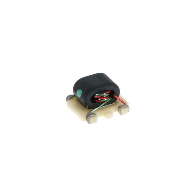
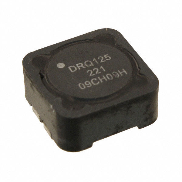
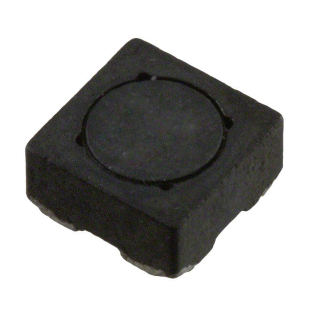
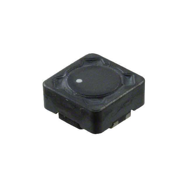
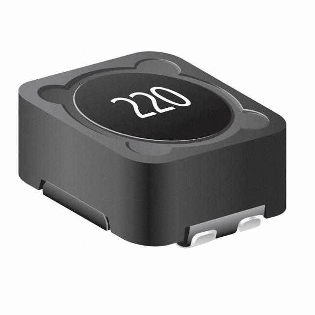
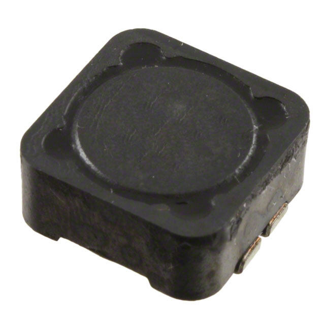
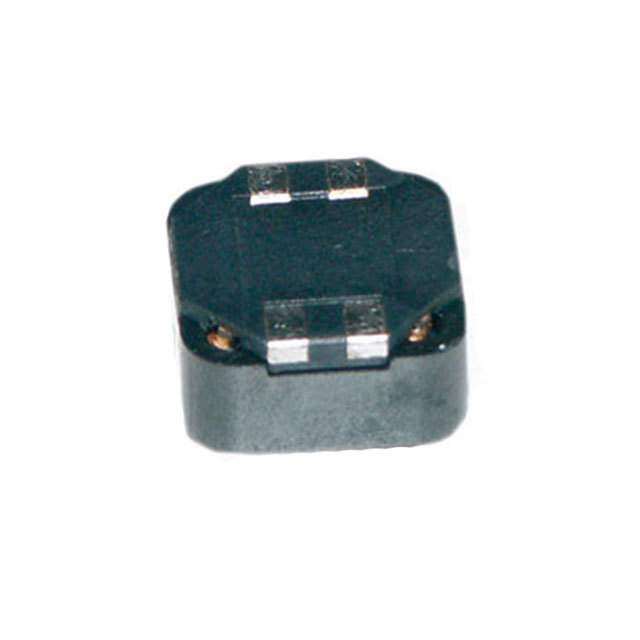
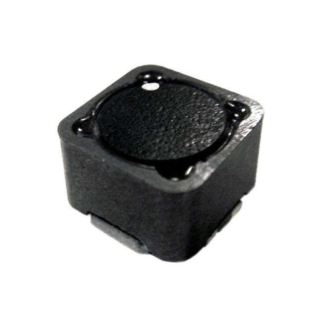
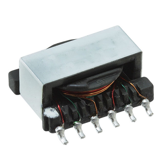
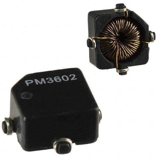
| 描述 | 变压器音频和信号 4-2000 MHZ WIDEBAND 4.5X4.5X2.8MM |
| 产品分类 | 变压器音频和信号 |
| 产品手册 | http://www.spraguegoodman.com/890/890glsw.html |
| 产品图片 |
|
| rohs | 符合RoHS |
| 产品系列 | Sprague Goodman GLSW4M202 |
| 产品型号 | GLSW4M202 |
| 产品 | Inductors |
| 产品种类 | 变压器音频和信号 |
| 初级线圈阻抗 | 50 Ohms |
| 商标 | Sprague Goodman |
| 宽度 | 4.5 mm |
| 封装 | Reel |
| 尺寸 | 4.5 mm L x 4.5 mm W x 2.8 mm H |
| 屏蔽 | Unshielded |
| 工作温度范围 | - 40 C to + 125 C |
| 工厂包装数量 | 50 |
| 次级线圈阻抗 | 50 Ohms |
| 端接类型 | SMD/SMT |
| 系列 | GLSW |
| 长度 | 4.5 mm |
| 频率范围 | 4 MHz to 2000 MHz |
| 高度 | 2.8 mm |


- 商务部:美国ITC正式对集成电路等产品启动337调查
- 曝三星4nm工艺存在良率问题 高通将骁龙8 Gen1或转产台积电
- 太阳诱电将投资9.5亿元在常州建新厂生产MLCC 预计2023年完工
- 英特尔发布欧洲新工厂建设计划 深化IDM 2.0 战略
- 台积电先进制程称霸业界 有大客户加持明年业绩稳了
- 达到5530亿美元!SIA预计今年全球半导体销售额将创下新高
- 英特尔拟将自动驾驶子公司Mobileye上市 估值或超500亿美元
- 三星加码芯片和SET,合并消费电子和移动部门,撤换高东真等 CEO
- 三星电子宣布重大人事变动 还合并消费电子和移动部门
- 海关总署:前11个月进口集成电路产品价值2.52万亿元 增长14.8%
PDF Datasheet 数据手册内容提取
ENGINEERING BULLETIN Sprague-Goodman SG-890A Supercedes SG-890.1 SURFCOIL® SMT INDUCTORS AND TRANSFORMERS (PROFESSIONAL GRADE) Sprague-Goodman Electronics,Inc. 1700 SHAMES DRIVE, WESTBURY, NY 11590 TEL: 516-334-8700 • FAX: 516-334-8771 E-MAIL: info@spraguegoodman.com
SURFACE MOUNT INDUCTORS AND TRANSFORMERS SG-890A SMD TUNABLE RF COIL 5.0 x 5.0 x 5.1 mm — GLSV & GLSA SERIES APPLICATIONS SPECIFICATIONS • RF circuits Operating Temperature Range: –40°C to +85°C • Telecommunications Power Loss at 40°C: approx. 100 mW max • Mobile radio Soldering Heat Resistance: 260°C, 5 s FEATURES Inductance Range: 14 nH - 680 µH • Compact design Frequency Range: 0.5 - 300 MHz • Suitable for automatic insertion • For reflow and vapor phase soldering • Wide frequency range • Max 5 connections 0.14 0.14 3.5 3.5 0.04TYP 0.9 0.02TYP 0.4 2 3 4 0.28 0.20 7.0 5.0 SQ 0.20 0.33 5.0 8.5 0.02 0.5 0.17 4.3 1 5 0.24 6.2 + 0.006 0.167 0.039 _ 0.000SQUARE 4.25 1.00 +_ 00..0105 PAD LAYOUT All dimensions are in /mm. Unless otherwise specified, the tolerance on dimensions is ±0.004/0.1. TYPICAL Q vs. INDUCTANCE TYPICAL Q vs. FREQUENCY 70 80 70 60 80MHz 60 0.02µH 50 0.4µH Q 40MHz Q 50 0.75µH 40 21.4MHz 40 1.3µH 30 10.7MHz 30 1.5µH 3.2µH 5MHz 20 30µH 20 1MHz 10 0.45MHz 10 0 0.01 0.1 1 10 100 1000 0.1 1 10 100 1000 INDUCTANCE (µH) FREQUENCY (MHz) 2 SPRAGUE-GOODMAN ELECTRONICS, INC., 1700 SHAMES DRIVE,WESTBURY, NY 11590• TEL: 516-334-8700 • FAX: 516-334-8771 • E-MAIL: info@spraguegoodman.com
SURFACE MOUNT INDUCTORS AND TRANSFORMERS SG-890A STANDARD VALUES (1 Winding) Inductance Frequency Q Test Pin Connection Inductance Test Freq. Range Adjustment Q Frequency Model (µH) (MHz) (MHz) Range min (MHz) A B Turns Number 0.047 10 50 - 200 ±3.0% 38 150 4 2 31/4 GLSV47N00 0.056 10 50 - 200 –6.0% 40 150 2 4 33/4 GLSV56N00 0.068 10 50 - 200 ±3.0% 45 150 2 4 33/4 GLSV68N00 0.082 10 50 - 200 ±3.5% 38 150 2 4 43/4 GLSV82N00 0.10 10 50 - 200 ±4.0% 48 100 2 4 43/4 GLSVR1000 0.12 10 50 - 200 ±5.0% 32 100 2 4 53/4 GLSVR1200 0.15 10 50 - 200 ±5.0% 42 100 2 4 53/4 GLSVR1500 0.18 10 50 - 200 ±5.0% 40 100 4 2 61/4 GLSVR1800 0.22 10 20 - 150 ±7.5% 45 70 4 2 71/4 GLSVR2200 0.27 10 20 - 150 ±7.5% 35 70 2 4 73/4 GLSVR2700 0.33 10 20 - 150 ±7.5% 35 70 2 4 83/4 GLSVR3300 0.39 10 20 - 150 ±7.5% 40 70 2 4 93/4 GLSVR3900 0.47 10 20 - 150 ±7.5% 45 70 4 2 111/4 GLSVR4700 0.56 10 20 - 150 ±7.5% 42 70 2 4 123/4 GLSVR5600 0.68 10 10 - 100 ±7.5% 45 50 4 2 141/4 GLSVR6800 0.82 10 10 - 100 ±7.5% 42 50 2 4 153/4 GLSVR8200 1.0 10 2 - 40 ±7.5% 42 50 4 2 171/4 GLSV1R000 1.2 10 2 - 40 ±7.5% 45 20 4 2 191/4 GLSV1R200 1.5 10 2 - 40 ±7.5% 45 20 4 2 211/4 GLSV1R500 1.8 10 2 - 40 ±7.5% 45 20 2 4 233/4 GLSV1R800 2.2 1 2 - 40 ±5.0% 45 20 2 4 273/4 GLSV2R200 2.7 1 2 - 40 ±5.0% 40 20 4 2 301/4 GLSV2R700 3.3 1 2 - 40 ±5.0% 35 20 4 2 341/4 GLSV3R300 3.9 1 2 - 40 ±5.0% 35 10 2 4 343/4 GLSV3R900 4.7 1 2 - 40 ±5.0% 35 10 2 4 383/4 GLSV4R700 5.6 1 2 - 40 ±5.0% 35 10 2 4 413/4 GLSV5R600 6.8 1 1 - 10 ±5.0% 30 5 4 2 441/4 GLSV6R800 8.2 1 1 - 10 ±5.0% 23 5 4 2 481/4 GLSV8R200 10.0 1 1 - 10 ±5.0% 23 5 4 2 551/4 GLSV10000 12.0 1 1 - 10 ±5.0% 23 5 4 2 611/4 GLSV12000 15.0 0.5 1 - 10 ±5.0% 25 5 4 2 671/4 GLSV15000 A B SPRAGUE-GOODMAN ELECTRONICS, INC., 1700 SHAMES DRIVE,WESTBURY, NY 11590• TEL: 516-334-8700 • FAX: 516-334-8771 • E-MAIL: info@spraguegoodman.com 3
SURFACE MOUNT INDUCTORS AND TRANSFORMERS SG-890A SPECIAL VALUES Induct. Freq. Q Test Pin Connection Turns Inductance Freq. Range Adjustment Q Freq. Turns Model (µH) (MHz) (MHz) Range min (MHz) A B C D E 1 2 A-E Fig. Number 0.014 10.0 100-200 ±3% 65 200 4 2 — — — 11/4 — — 1 GLSA14N00 0.092 10.0 50-200 ±5% 40 100 4 2 — — — 41/4 — — 1 GLSA92N00 0.117 1.0 20-200 ±4% 40 100 2 4 — — — 43/4 — — 1 GLSAR1170 0.137 10.0 20-150 ±5% 35 100 4 2 — — — 51/4 — — 1 GLSAR1370 0.17 1.0 20-150 ±5% 25 70 2 5 4 3 1 41/2 63/4 21/4 4 GLSAR1700 0.24 1.0 20-150 ±5% 30 70 1 5 4 2 — 71/4 51/4 — 3 GLSAR2400 0.24 1.0 20-150 +7/-4% 30 70 1 5 4 2 — 71/4 31/4 — 3 GLSAR2401 0.24 13.0 20-150 ±5% 30 35 1 5 — — — 71/4 — — 1 GLSAR2402 0.75 10.0 20-150 ±5% 25 30 1 2 5 4 — 143/4 151/4 — 3 GLSAR7500 0.85 1.0 20-150 ±7.5% 45 45 2 5 4 3 1 161/2 23/4 81/4 4 GLSAR8500 0.97 13.0 10-100 ±5% 40 35 4 2 1 5 — 16 2 — 3 GLSAR9700 1.0 1.0 10-100 -7.5% 25 45 2 5 — — 1 181/2 — 91/4 2 GLSA1R000 1.18 2.0 10-100 ±5% 22 40 2 4 5 1 3 183/4 33/4 141/4 4 GLSA1R180 1.2 1.0 10-100 +16% 38 20 4 2 1 5 — 201/4 41/4 — 3 GLSA1R200 1.3 1.0 10-100 ±7.5% 30 10 5 1 — — — 193/4 — — 1 GLSA1R300 1.35 0.3 10-100 ±5% 20 26 2 4 5 1 3 183/4 93/4 91/2 4 GLSA1R350 1.79 1.0 1 - 15 +3/–11% 25 12 2 4 5 1 — 223/4 43/4 — 3 GLSA1R790 2.0 0.2 5 - 50 ±5% 35 21 4 2 — — — 251/4 — — 1 GLSA2R000 2.15 13.0 5 - 40 ±7.5% 45 35 1 5 — — — 26 — — 1 GLSA2R150 2.5 13.0 5 - 40 ±7.5% 40 35 1 5 — — — 29 — — 1 GLSA2R500 3.0 0.2 5 -40 ±5% 30 21 2 4 — — 3 303/4 — 91/2 2 GLSA3R000 3.1 0.2 5 - 40 ±5% 32 21 4 2 — — — 32 — — 1 GLSA3R100 9.0 0.1 1 - 10 +21/-3% 18 1.6 2 4 5 1 — 553/4 113/4 — 3 GLSA9R000 19.6 0.1 1 - 10 +10/-1% 24 5.0 4 2 — — — 781/4 — — 1 GLSA19R60 28.0 0.1 1 - 10 +4/-16% 18 1.8 2 4 5 1 — 923/4 183/4 — 3 GLSA28000 32.0 1.0 1 - 10 +20% 14 1.0 1 5 4 2 — 1081/4 361/4 — 3 GLSA32000 125.0 0.1 0.5 - 2 ±7.5% 18 1.0 4 2 — — — 208 — — 1 GLSA12100 150.0 0.03 0.5 - 2 +10/-1.5% 16 1.0 5 1 4 2 — 2173/4 851/4 — 3 GLSA15100 390.0 0.1 0.5 - 2 ±7.5% 20 1.0 1 5 — — — 365 — — 1 GLSA39100 500.0 0.1 0.5 - 2 ±7.5% 12 0.5 4 2 — — — 426 — — 1 GLSA50100 680.0 0.05 0.5 - 2 ±7.5% 12 0.45 4 2 — — — 490 — — 1 GLSA68100 1 2 3 4 A A A A C C E E D D B B B B 4 SPRAGUE-GOODMAN ELECTRONICS, INC., 1700 SHAMES DRIVE,WESTBURY, NY 11590• TEL: 516-334-8700 • FAX: 516-334-8771 • E-MAIL: info@spraguegoodman.com
SURFACE MOUNT INDUCTORS AND TRANSFORMERS SG-890A SURFACE MOUNT TRANSFORMER 4.5 x 3.4 x 3.1 mm — GLSZ SERIES APPLICATIONS TYPICAL INSERTION LOSS • RF circuits 0 • Telecommunications PRIMARY • Mobile radio B A -1 FEATURES • Compact design -2 • Suitable for automatic insertion dB -3 • Suitable for all soldering methods 2.4 µH • Wide frequency range -4 0.8 µH SPECIFICATIONS Frequency Range: 25 kHz - 1 GHz -5 D C 0.22 µH Operating Temperature Range: SECONDARY –40°C to +125°C -6 1 2 5 101 2 5 102 2 5 103 Power Loss at 40°C: 100 mW max. FREQUENCY (MHz) Soldering Heat Resistance: 230°C, 8 s Insertion 3 dB Band Inductance Inductance Impedance Turns Loss Limits Primary Secondary Model (Ω) Ratio (dB) (MHz) (MHz) (µH) (µH) Figure Number 50:1100 1:4.7 1.1 15 65 0.24 4.7 B GLSZ112L4R7 50:140 1:1.66 1.6 0.2 5 32.7 79.0 B GLSZ141L790 50:1.25 6.33:1 4.3 4 60 0.9 0.034 B GLSZ1R3LR03 50:2000 1:6.33 2.7 100 340 0.036 0.98 B GLSZ202LR98 50:2.2 4.7:1 2.0 1 20 5.1 0.255 B GLSZ2R2LR26 50:370 1:2.71 1.6 30 400 0.15 0.9 B GLSZ371LR90 50:450 1:3 0.9 30 380 0.14 1.1 A GLSZ451L1R1 50:50 1:1 1.5 0.1 5 54.0 48.0 B GLSZ500L480 50:50 1:1 1.4 15 450 0.22 0.22 A GLSZ500LR22 50:500 1:3.15 1.5 0.7 28 6.5 55.0 A GLSZ501L550 50:50 1:1 3.1 40 580 0.08 0.08 A GLSZ500LR08 50:50 1:1 1.5 4 160 0.98 0.925 B GLSZ500LR93 50:5.6 3:1 2.5 4 60 1.1 0.14 A GLSZ5R6LR14 50:6.8 2.71:1 3.2 4 75 0.9 0.15 B GLSZ6R8LR15 50:800 1:4 1.5 20 150 0.23 3.3 A GLSZ801L3R3 FIGURE A FIGURE B 03..112 max 03..112 max D C D C 0.063 0.2 1.6 5.0 0.13 0.13 3.4 0.087TYP 3.4 0.075TYP 0.047TYP 2.2 0.047TYP 1.9 1.2 1.2 A D 0.031 A D 0.031 0.8 0.8 0.18 0.08 0.18 0.08 4.5 0.03 2.0 4.5 0.03 2.0 0.8 0.8 TYP B C TYP B C 0.039 DOT (ON TOP 1.0 0.087 0.20.958 SPTEUORRSMFITAIINOCANEL) OBDFE NOTES PAD LAYOUT 04..158 DSPUOORSTFI TA(IOOCNNE ) T ODOFEP N OTES P2A.2D LAYOUT TERMINAL B All dimensions are in /mm. Unless otherwise specified, the tolerance on dimensions is ±0.004/0.1. SPRAGUE-GOODMAN ELECTRONICS, INC., 1700 SHAMES DRIVE,WESTBURY, NY 11590• TEL: 516-334-8700 • FAX: 516-334-8771 • E-MAIL: info@spraguegoodman.com 5
SURFACE MOUNT INDUCTORS AND TRANSFORMERS SG-890A WIDEBAND TRANSFORMERS - 4.5 x 4.5 x 2.8 mm APPLICATIONS • RF circuits • Mobile radio 0.18 • Satellite TV 4.5 • Cordless phones 2 3 4 FEATURES • Compact design • Suitable for automatic insertion 0.18 4.5 • For reflow and vapor phase soldering • Ceramic base • Terminals are formed from the ends of the coil windings, eliminating solder joints between the 1 5 coil and the terminals which could open from the 0.12 heat of circuit assembly. 3.0 SPECIFICATIONS Operating Temperature Range: –40°C to +125°C Soldering Heat Resistance: 230°C, 5 s CONFIGURATION FOR BALUN TRANSFORMER (PAGE 7) TRANSFORMER WITH 2 WINDINGS 3 dB Loss at 20 MHz 1 5 Impedance Turns Band Limits (dB) Model (Ω) Ratio (MHz) max Number 50 : 50 1 : 1 4 - 2000 0.5 GLSW4M202 2 4 TYPICAL INSERTION LOSS 0 -1 -2 0.12 3.0 -3 -4 dB -5 -6 0.22 5.5 -7 -8 0.08 TYP 2.0 -9 -10 0.04 1 10 100 1000 10000 1.0 TYP FREQUENCY (MHz) PAD LAYOUT All dimensions are in /mm. Unless otherwise specified, the tolerance on dimensions is ±0.004/0.1. 6 SPRAGUE-GOODMAN ELECTRONICS, INC., 1700 SHAMES DRIVE,WESTBURY, NY 11590• TEL: 516-334-8700 • FAX: 516-334-8771 • E-MAIL: info@spraguegoodman.com
SSUURRFFAACCEE MMOOUUNNTT IINNDDUUCCTTOORRSS AANNDD TTRRAANNSSFFOORRMMEERRSS SSGG--889900AA TRANSFORMER WITH 2 WINDINGS AND CENTER TAP 3 dB Loss at 20 MHz 1 2 Turns Band Limits (dB) Model Ratio (MHz) max Number 1 : 1 : 1 4.5 - 1000 0.7 GLSB4R5M102 3 TYPICAL INSERTION LOSS 0 5 4 -1 -2 0.12 3.0 -3 -4 dB -5 0.059 -6 0.22 1.5 5.5 -7 -8 0.08TYP 2.0 -9 -10 0.04 1 10 100 1000 10000 1.0 TYP FREQUENCY (MHz) PAD LAYOUT BALUN TRANSFORMER 3 dB Loss at 20 MHz 1 2 Impedance Turns Band Limits (dB) Model (Ω) Ratio (MHz) max Number 50 : 200 1 : 2 10 - 1200 0.5 GLSU10M122 3 TYPICAL INSERTION LOSS 5 4 0 -1 0.12 -2 3.0 -3 -4 -5 dB 0.059 -6 0.22 1.5 5.5 -7 -8 0.08TYP 2.0 -9 -10 1 10 100 1000 10000 0.04TYP FREQUENCY (MHz) 1.0 PAD LAYOUT POWER SPLITTER Number Inductance Inductance 2 03..102 of (2 to 3) (2 to 4) Model 0.059 Turns (µH) (µH) Number 1.5 2 x 2 0.42 ± 25% 1.68 ± 25% GLSD02/02H1R68 3 0.08 2.0 All dimensions are in /mm. 0.04TYP Unless otherwise specified, the tolerance on dimensions is ±0.004/0.1. 4 1.0 PAD LAYOUT SPRAGUE-GOODMAN ELECTRONICS, INC., 1700 SHAMES DRIVE,WESTBURY, NY 11590• TEL: 516-334-8700 • FAX: 516-334-8771 • E-MAIL: info@spraguegoodman.com 7
SURFACE MOUNT INDUCTORS AND TRANSFORMERS SG-890A SMD WIDEBAND TRANSFORMER 6.5 x 5.7 x 4.0 mm — GLSJ SERIES APPLICATIONS FEATURES • RF circuits • Compact design • Mobile Radio • Suitable for automatic insertion • Satellite TV • For reflow and vapor phase soldering • Ceramic base SPECIFICATIONS • Terminals are formed from the ends of the coil Operating Temperature Range: –40°C to +125°C windings, eliminating solder joints between the Soldering Heat Resistance: 230°C, 5 s coil and the terminals which could open from the heat of circuit assembly. 5 2 1 dB Loss at 20 MHz 3 No. of Band Limits (dB) Model Turns (MHz) max Number 4 x 4.5 20 - 400 0.8 GLSJ4/5T401 1 4 4 x 2.5 20 - 750 0.8 GLSJ4/3T751 0.16 0.22 ± 0.006 4.0 5.7 ± 0.15 2 3 4 06..256 ±±0 0.0.1056 08..301 02..008 0.098 TYP 2.5 1 5 0.16 ± 0.004 0.047 4.0 ± 0.1 1.2 TYP PAD LAYOUT INSERTION LOSS - GLSJ4/5T401 INSERTION LOSS - GLSJ4/3T751 0 0 -2 -2 -4 -4 -6 -8 -6 dB dB -10 -8 -12 -10 -14 -12 -16 -18 -14 0.1 1 10 100 1000 10000 0.1 1 10 100 1000 10000 FREQUENCY (MHz) FREQUENCY (MHz) All dimensions are in /mm. Unless otherwise specified, the tolerance on dimensions is ±0.004/0.1. 8 SPRAGUE-GOODMAN ELECTRONICS, INC., 1700 SHAMES DRIVE,WESTBURY, NY 11590• TEL: 516-334-8700 • FAX: 516-334-8771 • E-MAIL: info@spraguegoodman.com
SURFACE MOUNT INDUCTORS AND TRANSFORMERS SG-890A SMD DIRECTIONAL COUPLER 5.7 x 5.7 x 4.0 mm — GLSN SERIES APPLICATIONS FEATURES • RF circuits • Compact design • Mobile Radio • Suitable for automatic insertion • Satellite TV • For reflow and vapor phase soldering • Ceramic base SPECIFICATIONS • Terminals are formed from the ends of the coil Operating Temperature Range: –40°C to +125°C windings, eliminating solder joints between the Soldering Heat Resistance: 230°C, 5 s coil and the terminals which could open from the heat of circuit assembly. 5 2 3 dB Loss at 20 MHz Coupling Band Limits (dB) Model (dB) (MHz) max Number 3 6 0.8 - 1100 2.8 GLSN2/6D112 8 0.8 - 1200 2.0 GLSN1/8D122 10 0.5 - 900 1.2 GLSN10D901 1 4 16 0.5 - 1500 0.6 GLSN16D152 0.22 ± 0.006 0.16 5.7 ± 0.15 4.0 2 3 4 05..272 ±± 0 0.0.1056 07..208 02..008 1 5 04.1.06 ±± 0 . 00.014 0.20.709TYP 0.10.427TYP PAD LAYOUT LOSS - GLSN16D152 COUPLING - GLSN16D152 0 0 -2 -2 -4 -6 -4 -8 -10 -6 -12 dB dB-14 -8 -16 -10 -18 -20 -12 -22 -24 -14 -26 0.1 1 10 100 1000 10000 0.1 1 10 100 1000 10000 FREQUENCY (MHz) FREQUENCY (MHz) All dimensions are in /mm. Unless otherwise specified, the tolerance on dimensions is ±0.004/0.1. SPRAGUE-GOODMAN ELECTRONICS, INC., 1700 SHAMES DRIVE,WESTBURY, NY 11590• TEL: 516-334-8700 • FAX: 516-334-8771 • E-MAIL: info@spraguegoodman.com 9
SURFACE MOUNT INDUCTORS AND TRANSFORMERS SG-890A SMD DIRECTIONAL COUPLER 4.5 x 4.5 x 2.8 mm — GLSL SERIES APPLICATIONS • RF circuits 0.18 • Mobile Radio 4.5 0.12 3.0 • Satellite TV 2 3 4 FEATURES • Compact design • Suitable for automatic insertion 0.18 0.22 0.10.559 • For reflow and vapor phase soldering 4.5 5.5 • Ceramic base • Terminals are formed from the ends of the coil 02..008TYP windings, eliminating solder joints between the 1 5 coil and the terminals which could open from the heat of circuit assembly. 03..102 01..004TYP PAD LAYOUT SPECIFICATIONS Operating Temperature Range: –40°C to +125°C Soldering Heat Resistance: 230°C, 5 s 5 2 3 3 dB Loss at 20 MHz Coupling Band Limits (dB) Model (db) (MHz) max Number 20 0.6 - 1700 0.2 GLSL20D102 1 4 SMD DIRECTIONAL COUPLER 6.5 x 5.7 x 4.0 mm — GLSY SERIES APPLICATIONS 0.16 • RF circuits 0.22 ± 0.006 4.0 5.7 ± 0.15 • Mobile Radio • Satellite TV 2 3 4 FEATURES • Compact design •• FSouirt arebflleo wfo ar nadu tvoampaotri cp hinasesert isoonldering 06..256 ±±0 0.0.1056 08..301 02..008 • Ceramic base • Terminals are formed from the ends of the coil 0.098 TYP windings, eliminating solder joints between the 2.5 coil and the terminals which could open from 1 5 the heat of circuit assembly. 0.16 ± 0.004 0.047 SPECIFICATIONS 4.0 ± 0.1 1.2 TYP PAD LAYOUT Operating Temperature Range: –40°C to +125°C Soldering Heat Resistance: 230°C, 5 s 5 2 3 dB Loss at 20 MHz 3 Coupling Band Limits (dB) Model (db) (MHz) max Number 10 0.5 - 900 1.2 GLSY10D901 1 4 20 0.5 - 1500 0.4 GLSY20D152 All dimensions are in /mm. Unless otherwise specified, the tolerance on dimensions is ±0.004/0.1. 10 SPRAGUE-GOODMAN ELECTRONICS, INC., 1700 SHAMES DRIVE,WESTBURY, NY 11590• TEL: 516-334-8700 • FAX: 516-334-8771 • E-MAIL: info@spraguegoodman.com
SURFACE MOUNT INDUCTORS AND TRANSFORMERS SG-890A CARRIER SPECIFICATIONS Dimension F G H K L M Model Series 0.47 0.08 0.16 0.22 0.012 0.63 GLSA, GLSV —--––––— —-—— —-–––— —-––— —-—— —-—–––– 12.0 2.0 4.0 5.6 0.3 16.0 0.31 0.08 0.16 0.13 0.012 0.47 GLSZ —--––— —-—— —--–––— —-––— —-—— ——–––– 8.0 2.0 4.0 3.2 0.3 12.0 GLSB, GLSD, 0.31 0.08 0.16 0.12 0.012 0.47 —--––––— —-—— —-—— —-––— —-—— ——–––– GLSU, GLSW 8.0 2.0 4.0 3.1 0.3 12.0 0.31 0.08 0.16 0.17 0.012 0.63 GLSJ, GLSY —-––––— —-— —-— —-–— —-—— —-—–––– 8.0 2.0 4.0 4.4 0.3 16.0 Carrier Outline Drawing H G L COVER TAPE M K F Not to scale. All dimensions are in/mm. REEL SPECIFICATIONS Qty. Reel Outline Drawing Dimension A B C D E Per D Model Series Reel 7 2.36 0.51 0.724 0.488 B GLSA, GLSV —--–––— —-––––— —-––— —-––––— ——— 1000 180 60.0 13.0 18.4 12.4 7 2.36 0.51 0.724 0.488 A B GLSZ –---–——- —-––––— —-—–— —-––––— ——— 2000 180 60.0 13.0 18.4 12.4 GLSB, GLSD, 7 2.36 0.51 0.724 0.488 —-–––– —-––––— —-–––— —-––––— ——— 2000 C GLSU, GLSW 180 60.0 13.0 18.4 12.4 7 2.36 0.51 0.882 0.646 E GLSJ, GLSY —-–––– ——— —-––––— —-—–––— —-––––— 1000 180 60.0 13.0 22.4 16.4 Not to scale. All dimensions are in/mm. SPRAGUE-GOODMAN ELECTRONICS, INC., 1700 SHAMES DRIVE,WESTBURY, NY 11590• TEL: 516-334-8700 • FAX: 516-334-8771 • E-MAIL: info@spraguegoodman.com 11
SURFACE MOUNT INDUCTORS AND TRANSFORMERS SG-890A Engineering Bulletin SG-890 describes a wide range resonant circuits. Non-tunable tapped coils and coils of fixed and variable surface mount inductors, coils, with multiple windings are also required for transformers and filters. Parts are wound as air coils, applications such as DC isolation,voltage and or on a selection of ferrite cores, and can be used current transformations and impedance matching up to the GHz frequency range. (between amplifier stages, for example). The SURFCOIL® models operate over the professional Fixed inductors are used in all areas of grade temperature of –40° to +125°C. (Sprague telecommunications, video and medical electronic Goodman’s selection of SURFCOIL SMT chip equipment. They are ideal in radio interference inductors, which operate over the temperature suppression devices, filters, and decoupling of range of –25° to +85°C, are described in Engineering oscillator and amplifier stages. Bulletin SG-800.) If the component you need for your design is not Our products are used in telecommunications and shown in this bulletin, let us know—the design you electronic engineering as frequency-selective need may already be in our design file, or we will components consisting of individual or coupled design a special to your specifications. Sprague-Goodman Electronics,Inc. 1700 SHAMES DRIVE, WESTBURY, NY 11590 TEL: 516-334-8700 • FAX: 516-334-8771 E-MAIL: info@spraguegoodman.com 12 ©2003 SPRAGUE-GOODMAN ELECTRONICS, INC., ALL RIGHTS RESERVED. PRINTED IN U.S.A. 2.50308