ICGOO在线商城 > 继电器 > 信号继电器,高达 2 A > G5V-2-DC12
 Datasheet下载
- 型号: G5V-2-DC12
- 制造商: Omron Electronics LLC
- 库位|库存: xxxx|xxxx
- 要求:
| 数量阶梯 | 香港交货 | 国内含税 |
| +xxxx | $xxxx | ¥xxxx |
查看当月历史价格
查看今年历史价格
G5V-2-DC12产品简介:
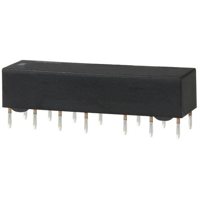
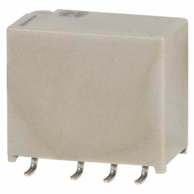
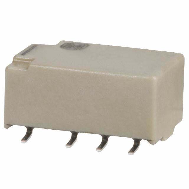
ICGOO电子元器件商城为您提供G5V-2-DC12由Omron Electronics LLC设计生产,在icgoo商城现货销售,并且可以通过原厂、代理商等渠道进行代购。 G5V-2-DC12价格参考。Omron Electronics LLCG5V-2-DC12封装/规格:信号继电器,高达 2 A, 通用 继电器 DPDT(2 Form C) 通孔。您可以下载G5V-2-DC12参考资料、Datasheet数据手册功能说明书,资料中有G5V-2-DC12 详细功能的应用电路图电压和使用方法及教程。
Omron Electronics Inc-EMC Div生产的G5V-2-DC12信号继电器是一款适用于多种工业和商业应用场景的小型继电器。该型号的继电器具有高达2A的负载能力,工作电压为12V直流电(DC12),广泛应用于需要精确控制和低功耗的场合。

 主要应用场景

1. 自动化控制系统:
   - 在工厂自动化中,G5V-2-DC12继电器可以用于控制各种传感器、执行器和其他低功率设备。例如,它可以用来控制电机启动/停止、灯光开关、报警系统等。

2. 楼宇自动化:
   - 该继电器可用于楼宇自动化系统中的照明控制、通风系统、空调系统的开关控制等。由于其体积小巧且功耗低,非常适合安装在空间有限的地方。

3. 智能家居设备:
   - 在智能家居系统中,G5V-2-DC12继电器可以用于控制智能插座、智能灯泡、窗帘电机等设备。它能够根据用户设定的时间或环境条件自动开关这些设备,提高生活便利性和节能效果。

4. 汽车电子:
   - 汽车内部有许多需要低电压控制的电路,如车内灯光、音响系统、雨刷控制器等。G5V-2-DC12继电器可以在这些场景中提供可靠的电气隔离和控制功能。

5. 医疗设备:
   - 在一些小型医疗设备中,如便携式监护仪、呼吸机等,G5V-2-DC12继电器可以用于控制电源开关、报警提示等功能,确保设备的安全运行。

6. 安全与安防系统:
   - 该继电器常用于门禁控制系统、监控摄像头的电源管理以及报警系统的触发机制。它能够在检测到异常情况时迅速切断或接通电路,保障系统的安全性。

7. 实验设备与测试仪器:
   - 在实验室环境中,G5V-2-DC12继电器可以用于控制实验设备的电源、信号传输线路的切换等,确保实验过程的稳定性和准确性。

总之,G5V-2-DC12信号继电器凭借其稳定的性能、紧凑的设计和广泛的适用性,成为众多行业中小型控制电路的理想选择。
| 参数 | 数值 |
| 产品目录 | |
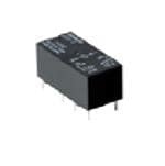
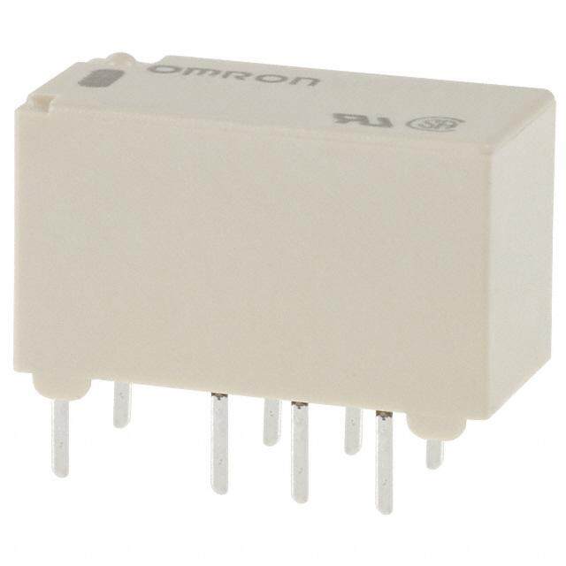
| 描述 | RELAY GEN PURPOSE DPDT 2A 12V低信号继电器 - PCB ThruHole Sealed DPDT 12VDC 500mW |
| 产品分类 | |
| 品牌 | Omron Electronics Inc-EMC Div |
| 产品手册 | |
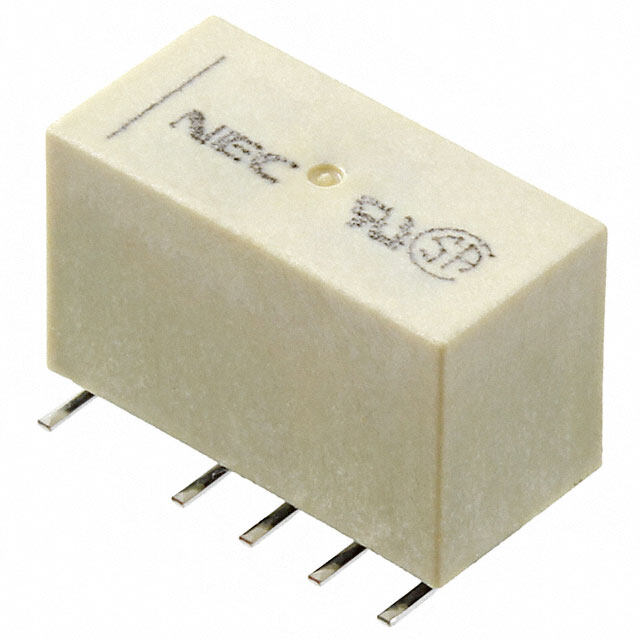
| 产品图片 |
|
| rohs | 符合RoHS无铅 / 符合限制有害物质指令(RoHS)规范要求 |
| 产品系列 | 低信号继电器 - PCB,Omron Electronics G5V-2-DC12G5V-2 |
| mouser_ship_limit | 该产品可能需要其他文件才能进口到中国。 |
| 数据手册 | |
| 产品型号 | G5V-2-DC12 |
| 产品 | Low Profile Relays |
| 产品培训模块 | http://www.digikey.cn/PTM/IndividualPTM.page?site=cn&lang=zhs&ptm=25458 |
| 产品目录绘图 |
|
| 产品目录页面 | |
| 产品种类 | 低信号继电器 - PCB |
| 关闭电压(最小值) | 0.6 VDC |
| 其它名称 | G5V 8036E |
| 其它有关文件 | |
| 功耗 | 500 mW |
| 包装 | 管件 |
| 商标 | Omron Electronics |
| 安装类型 | 通孔 |
| 安装风格 | Through Hole |
| 导通电压(最大值) | 9 VDC |
| 工作时间 | 7ms |
| 工作温度 | -25°C ~ 65°C |
| 工厂包装数量 | 25 |
| 开关电压 | 125VAC,125VDC - 最小值 |
| 最大开关电流 | 2 A |
| 标准包装 | 25 |
| 特性 | 密封式 - 全部 |
| 端子类型 | PC 引脚 |
| 端接类型 | Solder Pin |
| 类型 | Miniature |
| 系列 | G5V-2 |
| 线圈功率 | 500 mW |
| 线圈电压 | 12VDC |
| 线圈电流 | 41.7mA |
| 线圈电阻 | 288 欧姆 |
| 线圈类型 | 无锁存 |
| 继电器类型 | 通用 |
| 触头外形 | DPDT(2 C 型) |
| 触头材料 | Silver(Ag),Gold(Au) |
| 触点形式 | DPDT (2 Form C) |
| 触点电流额定值 | 2 A |
| 触点额定值 | 0.5 A at 125 VAC, 2 A at 30 VDC |
| 释放时间 | 3ms |
| 零件号别名 | 374710 G5V-8030F G5V212DC G5V212DCG5V2DC12NC G5V2DC12NC G5V8030F |
| 额定接触(电流) | 2A |


- 商务部:美国ITC正式对集成电路等产品启动337调查
- 曝三星4nm工艺存在良率问题 高通将骁龙8 Gen1或转产台积电
- 太阳诱电将投资9.5亿元在常州建新厂生产MLCC 预计2023年完工
- 英特尔发布欧洲新工厂建设计划 深化IDM 2.0 战略
- 台积电先进制程称霸业界 有大客户加持明年业绩稳了
- 达到5530亿美元!SIA预计今年全球半导体销售额将创下新高
- 英特尔拟将自动驾驶子公司Mobileye上市 估值或超500亿美元
- 三星加码芯片和SET,合并消费电子和移动部门,撤换高东真等 CEO
- 三星电子宣布重大人事变动 还合并消费电子和移动部门
- 海关总署:前11个月进口集成电路产品价值2.52万亿元 增长14.8%
PDF Datasheet 数据手册内容提取
G5V-2 Low Signal Relay General-purpose, Low-cost, Two-pole Relays for Signal Circults •General-purpose DIL terminal layout. (cid:129)Wide switching power of 10 μA to 2 A. (cid:129)Fully-sealed type Relays standardized with bifurcated crossbar contacts. Highly reliable in addition to its high environment resistance. (cid:129)Conforms to FCC Part 68 (impulse withstand voltage of 1,500 V for 10 x 160 µs between coil and contacts and between contacts of the same polarity). (cid:129)High dielectric strength at 1,000 VAC between coil and contacts, and 750 VAC between contacts of the same polarity. (cid:129)UL and CSA standard approved. RoHS Compliant ■Model Number Legend ■Application Examples G5V-@-@ 1. Number of Poles/ Contact form 2. Classification (cid:129)Telecommunication equipment — — 2: 2-pole/DPDT (2c) None: Standard (cid:129)Security equipment 1 2 H1: High-sensitivity ■Ordering Information ■Characteristics G 5 Minimum Item Classification Standard High-sensitivity V Enrcaltoinsgure Cfoonrtmact Teshrmapineal Model Rvaoteltda gceoil packing Contact resistance *1 50 mΩ max. 100 mΩ max. -2 Classification unit Operate time 7 ms max. 3 VDC Release time 3 ms max. 5 VDC Insulation resistance *2 1,000 MΩ min. (at 500 VDC) 6 VDC Between coil and Standard G5V-2 9 VDC contacts 1,000 VAC, 50/60 Hz for 1 min 12 VDC Dielectric Between contacts 750 VAC, 50/60 Hz 500 VAC, 50/60 Hz for Fully DPDT PCB 25 24 VDC strength of the same polarity for 1 min 1min sealed (2c) terminals pcs/tube 48 VDC Between contacts 1,000 VAC, 50/60 Hz for 1 min 5 VDC of different polarity High- 12 VDC Between coil and 1,500 V (10 x 160 μs) G5V-2-H1 contacts sensitivity 24 VDC Impulse 48 VDC withstand Bofe tthwee seanm ceo nptoalcatrsit y 1,500 V (10 x 160 μs) voltage Note:When ordering, add the rated coil voltage to the model number. Between contacts 1,500 V (10 x 160 μs) Example: G5V-2 DC3. of different polarity Rated coil voltage 10 to 55 to 10 Hz, 0.75 mm single amplitude Destruction However, the notation of the coil voltage on the product case as well as Vibration (1.5 mm double amplitude) on the packing will be marked as @@ VDC. resistance Malfunction 10 to 55 to 10 Hz, 0.75 mm single amplitude (1.5 mm double amplitude) Shock Destruction 1,000 m/s2 resistance Malfunction 200 m/s2 100 m/s2 15,000,000 operations min. Mechanical (at 36,000 operations/hr) Durability 100,000 operations AC: 100,000 operations min., DC: 300,000 Electrical min. (at 1,800 operations min. operations/hr) (at 1,800 operations/hr) Failure rate (P level) (reference 10 μA at 10 m VDC value) *3 -25°C to 65°C -25°C to 70°C Ambient operating temperature (with no icing or (with no icing or condensation) condensation) Ambient operating humidity 5% to 85% Weight Approx. 5 g Note:The above values are initial values. *1. The contact resistance was measured with 10 mA at 1 VDC with a voltage drop method. *2. The insulation resistance was measured with a 500 VDC megohmmeter applied to the same parts as those used for checking the dielectric strength. *3. This value was measured at a switching frequency of 120 operations/min and the criterion of contact resistance is 50 Ω. This value may vary depending on the switching frequency and operating environment. Always double-check relay suitability under actual operating conditions. 1
G5V-2 Low Signal Relay ■Ratings ●Coil ●Contacts Must Must Classification Standard High-sensitivity Max. Rated Coil operate release Power Load Resistive load Rated voltage Classificationvoltage c(umrrAen)t resi(sΩta)nce vo(ltVa)ge vo(ltVa)ge (V) con(smumWp)tion CCoonnttaacctt tmypaeterial BifuArgca +te Adu c-arollsosybar % of rated voltage 0.5 A at 125 VAC; 0.5 A at 125 VAC; 3 VDC166.7 18 Rated load 2 A at 30 VDC 1 A at 24 VDC 5 VDC100 50 Rated carry current 2 A 6 VDC 83.3 72 75% 5% 120% Approx. 500 Max. switching voltage 125 VAC, 125 VDC Standard 9 VDC 55.6 162 max. min. (at 23°C) Max. switching current 2 A 1 A 12 VDC 41.7 288 24 VDC 20.8 1,152 48 VDC 12 4,000 Approx. 580 5 VDC 30 166.7 180% Approx. 150 12 VDC 12.5 960 High- 75% 5% (at 23°C) 24 VDC 8.33 2,880 Approx. 200 sensitivity max. min. 150% 48 VDC 6.25 7,680 Approx. 300 (at 23°C) Note 1.The rated current and coil resistance are measured at a coil temperature of 23°C with a tolerance of ±10%. 2.Operating characteristics are measured at a coil temperature of 23°C. 3.The maximum voltage is the highest voltage that can be imposed on the relay coil. ■Engineering Data G ●Maximum Switching Capacity ●Durability 5 Standard/G5V-2 High-sensitivity/G5V-2-H1 Standard/G5V-2 High-sensitivity/G5V-2-H1 V - 2 Switching current (A)0.5215 DC resistive loadAC resistive load Switching current (A)00..53175 AC resistive load 4Durability (x10 operations)105310000 30 VDC resistive load 4Durability (x10 operations)105310000 125 VAC24 r eVsDisCtiv ree sloisatdive load 0.3 DC resistive load 5 125 VAC resistive load 5 3 3 0.2 0.1 0.1 1 1 0 10 30 50 100 300 500 0 10 30 50 70 125 300 500 0 1 2 3 0.5 1 1.5 Switching voltage (V) Switching voltage (V) Switching current (A) Switching current (A) ●Ambient Temperature vs. Maximum Coil Voltage Standard/G5V-2 High-sensitivity/G5V-2-H1 %)160 %)200 Maximum coil voltage (114200 3 to 24 VDC Maximum coil voltage (111864000 3 to 24 VDC 100 48 VDC 120 48 VDC 80 100 60 80 0 20 40 60 80 100 120 0 20 40 60 80 Ambient temperature (°C) Ambient temperature (°C) Note:The maximum coil voltage refers to the maximum value in a varying range of operating power voltage, not a continuous voltage. ●Ambient Temperature vs. Must Operate or Must Release Voltage ●Shock Malfunction Standard/G5V-2 High-sensitivity/G5V-2-H1 Standard/G5V-2 High-sensitivity/G5V-2-H1 On the basis of rated voltage (%)108640000 SNaummpbleer: oGf 5RVe-l2a ys: 10 pcs mmmmXXiiaannxx.... On the basis of rated voltage (%)108640000 SNaummpbleer: oGf 5RVe-l2a-yHs1: 10 pcs mmmXXmaiainnxx.... 11,,0000XZ00' Y246864210000000,0000000000Denee- rgized 11ZX,,00'0000 11,,0000XZ00' Y246864210000000,0000000000Denee-rgized 11ZX,,00'0000 200 MMuusstt orepleearastee vvoollttaaggee 200 MMuusstt orepleearastee vvoollttaaggee ShYoXck direXc'tZion Y'18,00000Unit: Emn/se2rgized ShYoXck direXc'tZion Y'18,000U00nit: m/Es2nergized -60 -40 -20 0 20 A4m0 bie6n0t tem8p0e ratu1r0e0 (1°C20) -60 -40 -20 0 20 A4m0 bie6n0t tem8p0e ratu1r0e0 (1°C20) Y' Z' SNaummpbleer: oGf 5RVe-l2a y1s2: V10D Cpcs Y' Z' SNaummpbleer: oGf 5RVe-l2a-yHs1: 1102 pVcDsC Conditions:Shock is applied in ±X, ±Y, and ±Z directions three times each with and without energizing the Relays to check the number of contact malfunctions. 2
G5V-2 Low Signal Relay ●Dial Pulse Test (with Must Operate and Must Release Voltage) *1 ●Dial Pulse Test ●Contact Reliability Test *1, *2 Standard/G5V-2 (Contact Resistance) *1 Standard/G5V-2 High-sensitivity/G5V-2-H1 On the basis of rated voltage (%)108640000SNTSMeawusmmuittsc pbcthl eoeoinrn:p godGe fifrt 5riaRoeVtenqe-ls2u av: ey oCnsltc:oa y1ng:0t ea1 pc,8tc 0slo0a odp WerJa-t9io2n6s/h mmianx.. ΩContact resistance (m)1,053100000000SNTlS1o,eawua8smmdi0ttc 0pbWch leooeiJnrnp: - gode9G fir2ft 5ariR6oeVtienqo-ls2una: esy Cn/shc:o y1n:0t a pctc s NNOC mmccooaannxxtt..aacctt ΩContact resistance (m)1,053100000000 SNTSeawusmmittc pbcNNhleoeiOCnrn: g odGcc fiooft 5riRnnoeVttenqaa-ls2ucac: etty 1ns0c: y1μ:0 A7 p,r2ce0ss0is otivpee rlaotaiodn ast/ h10 mVDC mmaaxx.. ΩContact resistance (m)1,053100000000SNTSeawusmmittc pbcNNhleoeiOCnrn: g odGcc fiofot 5riRnoneVtentqa-als2uacc:-ety tH1ns01c: y1μ:0 A7 p,r2ce0ss0is otivpee rlaotaiodn ast/ h10 mVDC mmaaxx.. 50 50 50 min. 20 Must release voltage max. 30 mmiinn.. 30 mmiinn.. 30 min. min. 10 10 10 0 0.3 0.5 1 3 5 10 30 50 100 300 0 0.3 0.5 1 3 5 10 30 50 100 300 0 5 10 50 100 500 1,000 0 5 10 50 100 500 1,000 Operating frequency (×103 operations) Operating frequency (×103 operations) Operating frequency (×104 operations) Operating frequency (×104 operations) *1. The tests were conducted at an ambient temperature of 23°C. *2. The contact resistance data are periodically measured reference values and are not values from each monitoring operation. Contact resistance values will vary according to the switching frequency and operating environment, so be sure to check operation under the actual operating conditions before use. ●High-frequency Characteristics (cid:129)Measurement Conditions G5V-2 HR 8502A RF HR 8502A Naneatwlyozrekr 850H1PA RA Trteersfalten-csstemiotinssion 50Ω G5 norSmtoarlaizgeer B Terminator Note:The high-frequency characteristics data were measured using a dedicated circuit board and V Terminals which were not being measured were terminated with 50 Ω. actual values will vary depending on the usage conditions. Check the characteristics of the actual -2 Measuring impedance: 50 Ω equipment being used. ●High-frequency Characteristics ●High-frequency Characteristics ●High-frequency Characteristics (Isolation) *1, *2 (Insertion Loss) *1, *2 (Return Loss, V.SWR) *1, *2 (Average value (initial)) (Average value (initial)) (Average value (initial)) Isolation (dB) 24000 SNaummpbleer: oGf 5RVe-l2ayBs:e 5tw pecesn b-c Insertion loss (dB)0.005 Return loss (dB) 24000 SNaummpbleeBr: eoGtfw 5ReVee-l2na ycs-:b 10 pcs V.SWR 111...543 V.SWR Between c-b 0.1 Between c-a 60 Between a-b 60 1.2 Return loss Between c-a 0.15 80 80 1.1 Sample: G5V-2 Number of Relays: 5 pcs 100 0.2 100 1.0 0.5 1 3 5 10 30 50 100 300 500 0.5 1 3 5 10 30 50 100 0.5 1 3 5 10 30 50 100 300 500 Frequency (MHz) Frequency (MHz) Frequency (MHz) ●Must Operate and Must ●Distribution of Bounce ●Must Operate and Must ●Distribution of Bounce Release Time Distribution *1 Time *1 Release Time Distribution *1 Time *1 Standard/G5V-2 High-sensitivity/G5V-2-H1 mber of contacts10800SNaummpbleer: oGf 5RVe-l2a y 1s2: 5V0D pCcs MMuusstt orepleearastee ttiimmee mber of contacts4300S1NR2aue mmlVapyDbsleCe:r : 5 oG0f 5 pVc-s2 ORepleeraastien gb obuonucnec eti mtimee mber of contacts60 SNaummpbleer: oGf 5RVe-l2a-yHs1: 50 pcs MMuusstt orepleearastee ttiimmee mber of contacts8600 SGNRaue5mmlVa-pyb2slee-:Hr : 5 o10f pcs ORepleeraastien gb obuonucnec eti mtimee Nu Nu Nu40 Nu 60 20 40 40 20 10 20 20 0 0.5 1 1.5 2 2.5 3 3.5 4 4.5 5 0 0.5 1 1.5 2 2.5 3 3.5 4 4.5 5 0 0.5 1 1.5 2 2.5 3 3.5 4 4.5 5 5.5 6 0 0.5 1 1.5 2 2.5 3 3.5 4 4.5 5 5.5 6 Time (ms) Time (ms) Time (ms) Time (ms) *1. The tests were conducted at an ambient temperature of 23°C. *2. High-frequency characteristics depend on the PCB to which the Relay is mounted. Always check these characteristics, including endurance, in the actual machine before use. 3
G5V-2 Low Signal Relay ■Dimensions G5V-2 PCB Mounting Holes (Bottom View) Terminal Arrangement/ Tolerance: ±0.1 mm Internal Connections 10.1max. 20.5max. (9.9)* 2.54 (Bottom View) (20.3)* Eight, 1 dia. holes 11.5max. 2.54 (1.2) 1 4 6 8 0.5 (11.4)* 7.62 (1.2) 16 13 11 9 0.4 (No coil polarity) 0.3 7.62 5.08 5.08 0.5 7.62 3.5 (1.3) (1.3) * Average value Orientation marks are indicated as follows: Note:Each value has a tolerance of ±0.3 mm. ■Approved Standards ■Precautions UL recognized: (File No. E41515) (cid:129)Please refer to “PCB Relays Common Precautions” for correct use. CSA certified: (File No. LR31928) Correct Use Contact ratings Number of Contact Coil Model test •Long-term Continuously ON Contacts form ratings G5V-2 G5V-2-H1 operations Using the Relay in a circuit where the Relay will be ON DPDT 3 to 48 2 A, 30 VDC at 40°C 2 A, 24 VDC at 40°C continuously for long periods (without switching) can lead to G5V-2 0.6 A, 110 VDC at 40°C0.2 A, 110 VDC at 40°C 6,000 (2c) VDC unstable contacts because the heat generated by the coil itself 0.6 A, 125 VAC at 40°C 0.5 A, 125 VAC at 40°C will affect the insulation, causing a film to develop on the contact G surfaces. Be sure to use a fail-safe circuit design that provides 5 protection against contact failure or coil burnout. V (cid:129)Relay Handling - 2 When washing the product after soldering the Relay to a PCB, use a water-based solvent or alcohol-based solvent, and keep the solvent temperature to less than 40°C. Do not put the Relay in a cold cleaning bath immediately after soldering. · Application examples provided in this document are for reference only. In actual applications, confirm equipment functions and safety before using the product. · Consult your OMRON representative before using the product under conditions which are not described in the manual or applying the product to nuclear control systems, railroad systems, aviation systems, vehicles, combustion systems, medical equipment, amusement machines, safety equipment, and other systems or equipment that may have a serious influence on lives and property if used improperly. Make sure that the ratings and performance characteristics of the product provide a margin of safety for the system or equipment, and be sure to provide the system or equipment with double safety mechanisms. Note: Do not use this document to operate the Unit. OMRON Corporation Electronic and Mechanical Components Company Contact: www.omron.com/ecb Cat. No. K046-E1-06 0316(0207)(O) 4
Mouser Electronics Authorized Distributor Click to View Pricing, Inventory, Delivery & Lifecycle Information: O mron: G5V-2-H1-DC9 G5V-2-H1-DC6 G5V-2-H1-DC5 G5V-2-DC5 G5V-2-H1-DC24 G5V-2-H1-DC12 G5V-2-H-DC5 G5V-2-H-DC12 G5V-2-H-DC24 G5V-2-DC24 G5V-2-DC12 G5V-2-DC9 G5V-2-H-DC3 G5V-2-H-DC6 G5V-2-H-DC9 G5V-2 DC4.5 G5V-2-DC48 G5V-2-DC6 G5V-2-H1-DC48 G5V-2-DC3 G5V-2-H1 DC3 G5V-2-H DC48 G5V-2-Y DC12 BY OMZ G5V-2-Y DC5 G5V-2-FD DC12