ICGOO在线商城 > 继电器 > 信号继电器,高达 2 A > EE2-5TNUH-L
 Datasheet下载
- 型号: EE2-5TNUH-L
- 制造商: Kemet
- 库位|库存: xxxx|xxxx
- 要求:
| 数量阶梯 | 香港交货 | 国内含税 |
| +xxxx | $xxxx | ¥xxxx |
查看当月历史价格
查看今年历史价格
EE2-5TNUH-L产品简介:
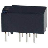
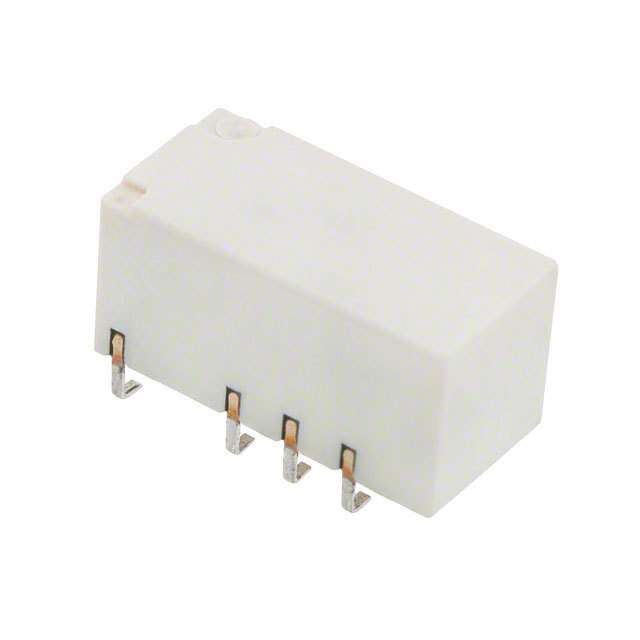
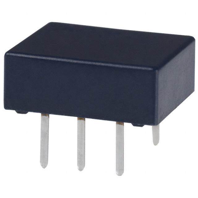
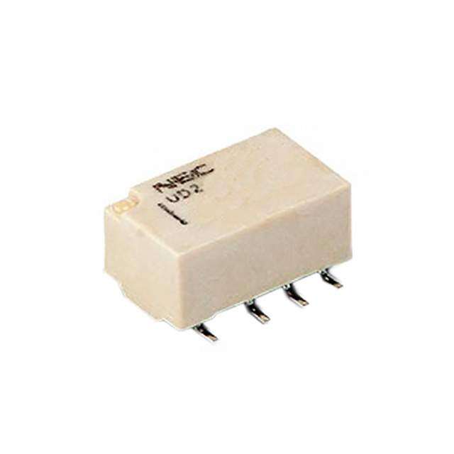
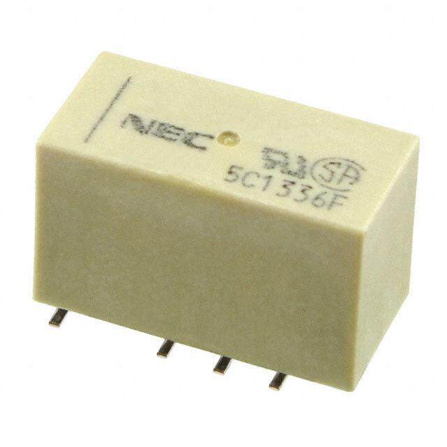
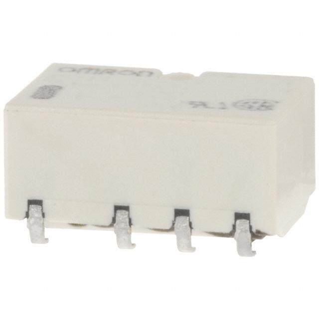
ICGOO电子元器件商城为您提供EE2-5TNUH-L由Kemet设计生产,在icgoo商城现货销售,并且可以通过原厂、代理商等渠道进行代购。 EE2-5TNUH-L价格参考。KemetEE2-5TNUH-L封装/规格:信号继电器,高达 2 A, 通用 继电器 DPDT(2 Form C) 表面贴装。您可以下载EE2-5TNUH-L参考资料、Datasheet数据手册功能说明书,资料中有EE2-5TNUH-L 详细功能的应用电路图电压和使用方法及教程。
KEMET品牌的信号继电器型号EE2-5TNUH-L,具有高达2A的切换能力,适用于多种工业和商业场景。以下是其主要应用场景:

 1. 工业自动化控制
   - 用于PLC(可编程逻辑控制器)或DCS(分布式控制系统)中的信号切换。
   - 控制小型电机、传感器、指示灯等低功率负载。
   - 在生产线中实现信号隔离和放大,确保系统的稳定性和安全性。

 2. 通信设备
   - 用于路由器、交换机或其他网络设备中的信号切换。
   - 提供高可靠性的信号传输,支持数据通信中的开关功能。

 3. 家用电器
   - 应用于智能家居设备,如智能插座、温控器或灯光控制系统。
   - 控制小功率家电设备的开/关状态,例如风扇、加湿器等。

 4. 汽车电子
   - 用于车载信息娱乐系统、导航设备或报警系统的信号切换。
   - 支持车内低功率电路的控制,如车窗升降、雨刷器等功能。

 5. 医疗设备
   - 在便携式医疗仪器中,用于信号隔离和控制。
   - 确保设备的稳定运行,同时避免电磁干扰对信号的影响。

 6. 安防系统
   - 用于监控摄像头、门禁系统或报警装置的信号控制。
   - 实现远程开关功能,提高系统的灵活性和安全性。

 特点与优势:
- 高可靠性:KEMET品牌以高质量著称,EE2-5TNUH-L在恶劣环境下仍能保持稳定性能。
- 小型化设计:适合空间有限的应用场合,便于集成到各种设备中。
- 长寿命:机械寿命和电气寿命均表现优异,减少维护成本。
- 低功耗:适合需要节能的应用场景。

综上,EE2-5TNUH-L型号的信号继电器广泛应用于工业、通信、家电、汽车、医疗和安防等领域,能够满足多样化的需求。
| 参数 | 数值 |
| 产品目录 | |
| 描述 | RELAY GEN PURPOSE DPDT 2A 5V低信号继电器 - PCB 5V 10uA Relay Signal 2formC |
| 产品分类 | |
| 品牌 | KEMET NEC TOKINKemet |
| 产品手册 | http://www.kemet.com/docfinder?Partnumber=EE2-5TNUH-L |
| 产品图片 |
|
| rohs | 符合RoHS无铅 / 符合限制有害物质指令(RoHS)规范要求 |
| 产品系列 | 低信号继电器 - PCB,KEMET NEC TOKIN EE2-5TNUH-LEE2 |
| mouser_ship_limit | 该产品可能需要其他文件才能进口到中国。 |
| 数据手册 | http://www.kemet.com/docfinder?Partnumber=EE2-5TNUH-L |
| 产品型号 | EE2-5TNUH-LEE2-5TNUH-L |
| 产品 | Slim Form Relays |
| 产品种类 | 低信号继电器 - PCB |
| 关闭电压(最小值) | - |
| 其它名称 | 399-11020-1 |
| 功耗 | 140 mW |
| 包装 | 剪切带 (CT) |
| 商标 | KEMET NEC TOKIN |
| 安装类型 | 表面贴装 |
| 安装风格 | SMD/SMT |
| 导通电压(最大值) | 3.75 VDC |
| 封装 | Reel |
| 工作时间 | 2ms |
| 工作温度 | -40°C ~ 85°C |
| 工厂包装数量 | 500 |
| 开关电压 | 250VAC,220VDC - 最小值 |
| 最大开关电流 | 2 A |
| 标准包装 | 1 |
| 特性 | - |
| 特色产品 | http://www.digikey.cn/product-highlights/zh/ee2-and-ec2-electromechanical-signal-relays/50473 |
| 端子类型 | 鸥翼型 |
| 端接类型 | Gull Wing Lead |
| 类型 | Miniature |
| 线圈功率 | 140 mW |
| 线圈电压 | 5VDC5 V |
| 线圈电流 | 28mA |
| 线圈电阻 | 178 欧姆 |
| 线圈类型 | 锁存,双线圈Dual Coil Latching |
| 继电器类型 | 通用 |
| 触头外形 | DPDT(2 C 型) |
| 触头材料 | 银合金,金合金 |
| 触点形式 | DPDT (2 Form C) |
| 触点电流额定值 | 2 A |
| 释放时间 | 1ms |
| 额定接触(电流) | 2A |


- 商务部:美国ITC正式对集成电路等产品启动337调查
- 曝三星4nm工艺存在良率问题 高通将骁龙8 Gen1或转产台积电
- 太阳诱电将投资9.5亿元在常州建新厂生产MLCC 预计2023年完工
- 英特尔发布欧洲新工厂建设计划 深化IDM 2.0 战略
- 台积电先进制程称霸业界 有大客户加持明年业绩稳了
- 达到5530亿美元!SIA预计今年全球半导体销售额将创下新高
- 英特尔拟将自动驾驶子公司Mobileye上市 估值或超500亿美元
- 三星加码芯片和SET,合并消费电子和移动部门,撤换高东真等 CEO
- 三星电子宣布重大人事变动 还合并消费电子和移动部门
- 海关总署:前11个月进口集成电路产品价值2.52万亿元 增长14.8%
PDF Datasheet 数据手册内容提取
Miniature Signal Relays EC2/EE2 Series Overview Applications The KEMET EC2/EE2 miniature signal relays offer a • Electronic switching systems compact case size in a slim package. Minimal board space • PBX is consumed with either a through-hole or surface mount • Terminal equipment configuration. These relays are recognized by UL and CSA, • Telephone systems while also being compliant with Part 68 of the FCC’s 1,500 V surge capacity. Benefits • Low power consumption (< 200 mW) • Compact and lightweight • Low magnetic interference • Tube or embossed tape and reel packaging • UL recognized (E73266) and CSA certified (LR46266) • Surface mount and through-hole options • High Breakdown Voltage (NKX) type can withstand 1.5 kVAC at open contacts Part Number System EE2- 3 S NU -L Series Coil Voltage Latch Type Lead Type Packaging EC2- = Through-hole mount 3 = 3 VDC Blank = Non-latch type NU = Standard Blank = Tube EE2- = Surface mount 4.5 = 4.5 VDC S = Single coil latch type NUH = Minimum footprint -L = Embossed tape on reel 5 = 5 VDC T = Double coil latch type NUX = High solder joint reliability 12 = 12 VDC NKX = High breakdown voltage and 24 = 24 VDC high solder joint reliability One world. One KEMET © KEMET Electronics Corporation • P.O. Box 5928 • Greenville, SC 29606 • 864-963-6300 • www.kemet.com R7002_EC2_EE2 • 8/8/2017 1
Miniature Signal Relays – EC2/EE2 Series D Maximum B Maximum D Maximum B Maximum Dimensions – Millimeters EC2 Series H Maximum H Maximum Non-latch type and single coil latch type Double coil latch type 0.5 D Maximum K 0.25B Maximum 0.5 D Maximum K 0.25B Maximum 5.08 P1 P1 P2 5.08 P P P P H Maximum 1 1 1 H Maximum 2 0.5 K 0.25 0.5 K 0.25 5.08 P1 P1 P2 5.08 P P P P 1 1 1 2 EE2 Series Non-latch type and single coil latch type Double coil latch type D Maximum B Maximum D Maximum B Maximum H Maximum H Maximum 0.5 0.25 0.5 0.25 D Maximum B Maximum D Maximum B Maximum P P 5.08 P P K 2 5.08 P P P K 2 1 1 1 1 1 P P 3 3 H Maximum H Maximum 0.5 0.25 0.5 0.25 Series D H B P P P K 1 2 3 P P EC2 (N5U.0)8 P1 P115.0 K 9.4 7.5 2 2.54 5.08 5.0—8 P1 P13.2P1 K 2 EE2 (NU) 15.0 10.0 7.5 P 2.54 5.08 9.5 1.0 P 3 3 EE2 (NUH) 15.0 10.0 7.5 2.54 5.08 7.5 1.0 EE2 (NUX, NKX) 15.0 10.35 7.5 2.54 5.08 9.0 1.35 General tolerance: ±0.2 © KEMET Electronics Corporation • P.O. Box 5928 • Greenville, SC 29606 • 864-963-6300 • www.kemet.com R7002_EC2_EE2 • 8/8/2017 2
Miniature Signal Relays – EC2/EE2 Series Pin Configurations Bottom view Non-latch type Single coil latch type Double coil latch type (Non-energized position) (Reset position) (Reset position) 1 3 4 5 1 3 4 5 1 3 4 5 6 ark + ark + - ark + + m m m on on S R on cti cti cti e e e Dir - Dir - + Dir - - 12 10 9 8 12 10 9 8 12 10 9 8 7 S: Coil polarity for Set Set coil Reset coil R: Coil polarity for Reset Safety Standards and Ratings Certification Body Mark Specification File Number Rating UL Recognized UL E73266 (UL508)1 30 VDC, 2 A (resistive) 110 VDC, 0.3 A (resistive) CSA Certified 125 VAC, 0.5 A (resistive) CSA LR46266 (CSA 22.2 #14) 1 Spacing: UL114, UL478 Certification Mark Lead Type Specification File Number Class Rating Body Creepage and clearance NU, NUH, NUX TUV Certified of coil to contact is TUV R 9751153 Basic insulation (Non-latch and Single coil) (EN61810) more than 2 mm (According to EN60950) Environmental Compliance All KEMET relays are RoHS Compliant. RoHS Compliant © KEMET Electronics Corporation • P.O. Box 5928 • Greenville, SC 29606 • 864-963-6300 • www.kemet.com R7002_EC2_EE2 • 8/8/2017 3
Miniature Signal Relays – EC2/EE2 Series Table 1 – Ratings & Part Number Reference Nominal Coil Voltage Part Number Lead Type Packaging (VDC) EC2-3(1)NU 3 Radial Tube EC2-4.5(1)NU 4.5 Radial Tube EC2-5(1)NU 5 Radial Tube EC2-12(1)NU 12 Radial Tube EC2-24(1)NU 24 Radial Tube EE2-3(1)NU 3 Surface mount Tube EE2-4.5(1)NU 4.5 Surface mount Tube EE2-5(1)NU 5 Surface mount Tube EE2-12(1)NU 12 Surface mount Tube EE2-24(1)NU 24 Surface mount Tube EE2-3(1)NU-L 3 Surface mount Tape on Reel EE2-4.5(1)NU-L 4.5 Surface mount Tape on Reel EE2-5(1)NU-L 5 Surface mount Tape on Reel EE2-12(1)NU-L 12 Surface mount Tape on Reel EE2-24(1)NU-L 24 Surface mount Tape on Reel EE2-3(1)NUH 3 Surface mount, Minimum footprint Tube EE2-4.5(1)NUH 4.5 Surface mount, Minimum footprint Tube EE2-5(1)NUH 5 Surface mount, Minimum footprint Tube EE2-12(1)NUH 12 Surface mount, Minimum footprint Tube EE2-24(1)NUH 24 Surface mount, Minimum footprint Tube EE2-3(1)NUH-L 3 Surface mount, Minimum footprint Tape on Reel EE2-4.5(1)NUH-L 4.5 Surface mount, Minimum footprint Tape on Reel EE2-5(1)NUH-L 5 Surface mount, Minimum footprint Tape on Reel EE2-12(1)NUH-L 12 Surface mount, Minimum footprint Tape on Reel EE2-24(1)NUH-L 24 Surface mount, Minimum footprint Tape on Reel EE2-3(1)NUX 3 Surface mount, High solder joint reliability Tube EE2-4.5(1)NUX 4.5 Surface mount, High solder joint reliability Tube EE2-5(1)NUX 5 Surface mount, High solder joint reliability Tube EE2-12(1)NUX 12 Surface mount, High solder joint reliability Tube EE2-24(1)NUX 24 Surface mount, High solder joint reliability Tube EE2-3(1)NUX-L 3 Surface mount, High solder joint reliability Tape on Reel EE2-4.5(1)NUX-L 4.5 Surface mount, High solder joint reliability Tape on Reel EE2-5(1)NUX-L 5 Surface mount, High solder joint reliability Tape on Reel EE2-12(1)NUX-L 12 Surface mount, High solder joint reliability Tape on Reel EE2-24(1)NUX-L 24 Surface mount, High solder joint reliability Tape on Reel EE2-3NKX1 3 Surface mount, High breakdown voltage, High solder joint reliability Tube EE2-4.5NKX1 4.5 Surface mount, High breakdown voltage, High solder joint reliability Tube EE2-12NKX1 12 Surface mount, High breakdown voltage, High solder joint reliability Tube EE2-3NKX-L1 3 Surface mount, High breakdown voltage, High solder joint reliability Tape on Reel EE2-4.5NKX-L1 4.5 Surface mount, High breakdown voltage, High solder joint reliability Tape on Reel EE2-12NKX-L1 12 Surface mount, High breakdown voltage, High solder joint reliability Tape on Reel (1) To complete KEMET part number, leave blank for Non-latch, insert S for Single coil, or T for Double coil. Designates latch type. 1 NKX type only available as Non-latch. Non-standard part, please contact KEMET to special order. © KEMET Electronics Corporation • P.O. Box 5928 • Greenville, SC 29606 • 864-963-6300 • www.kemet.com R7002_EC2_EE2 • 8/8/2017 4
Miniature Signal Relays – EC2/EE2 Series Land Pattern – Millimeters EC2 Series (bottom view) Non-latch type and single coil latch type Double coil latch type 1.05 1.055.08 52..0584 2.524.54 2.54 8 - ø 0.88 - ø 0.8 1.05 1.055.08 25..5048 2.524.542.524.54 2.548 - ø 0.88 - ø 0.8 1.05 1.055.08 2.55.4082.542.54 2.548 - ø 0.8 8 - ø 0.8 1.05 1.055.08 2.554.082.542.25.4542.54 2.584 - ø 0.8 8 - ø 0.8 V V V V V V V V 1.11 1.11 1.11 1.11 1.11 1.11 1.11 1.11 EE2 Series (top view) Non-latch type and single coil latch type Double coil latch type 1.05 1.055.08 25..50482.524.542.54 1.05 1.055.08 25..50482 .524.524.524.542.54 1.05 1.055.08 2.554.028.542.542.54 1.05 1.055.08 2.554.028.5 422.5.5442.542.54 V V V V V V V V X X X X X X X X 1.11 1.11 1.11 1.11 1.11 1.11 1.11 1.11 Series V X EC2 5.08 — EE2 (NU) 7.29 3.0 EE2 (NUH) 6.29 2.0 EE2 (NUX, NKX) 7.02 2.73 D MaxDim Muamximum B MaxBim Muamximum D MaxDim Muamximum B MaxBim Muamximum D MaximD uMmaximum B MaximB uMmaximum D MaximD uMmaximum B MaximB uMmaximum H MaxHim Muamximum H MaxHim Muamximum H MaxiHm uMmaximum H MaxiHm uMmaximum 0.5 0.50.50.5 K K 0.2 0.2 0.5 0.5 K K 0.2 0.2 K K0.2 0.2 0.5 0.5 K K 0.2 0.2 5.085.0P581.0P5P8.1108PP11PP11P1 P2 P2 P2P2 5.085.0P581.0P58P.1018PPP111PPP111PP11P1 P2 P2 P2P2 © KEMET Electronics Corporation • P.O. Box 5928 • Greenville, SC 29606 • 864-963-6300 • www.kemet.com R7002_EC2_EE2 • 8/8/2017 5
Miniature Signal Relays – EC2/EE2 Series Soldering Process EC2 – Through-hole Mounting Automatic Soldering Preheating: 110–120°C/110 seconds (maximum) Solder temperature: 260°C maximum Solder time: 5 seconds maximum Note: KEMET recommends cooling down a printed circuit board to less than 110°C within 40 seconds after soldering. Manual Soldering Solder temperature: 350°C maximum Solder time: 3 seconds maximum EE2 – Surface Mounting IRS Method Temperature (˚C) Maximum 240˚C 222200 220000 118800 45 (Maximum 70) Time (seconds) 70 (Maximum 120) 190 (Maximum 300) Note: Temperature profile shows printed circuit board surface temperature on the relay terminal portion. Please consult KEMET if you wish to use a temperature profile other than above. © KEMET Electronics Corporation • P.O. Box 5928 • Greenville, SC 29606 • 864-963-6300 • www.kemet.com R7002_EC2_EE2 • 8/8/2017 6
Miniature Signal Relays – EC2/EE2 Series Contact Specifications Item EC2/EE2 Contact Form 2 Form C Contact Material Silver alloy with gold alloy overlay Maximum Switching Power 60 W, 125 VA Maximum Switching Voltage 220 VDC, 250 VAC Contact Ratings Maximum Switching Current 2 A Maximum Carrying Current 2 A Minimum Contact Ratings 10 mVDC, 10 µA*1 Initial Contact Resistance 75 mΩ maximum (initial) Operating Time (excluding bounce) Approximately 2 milliseconds Release Time (excluding bounce) Approximately 1 millisecond Insulation Resistance 1,000 MΩ at 500 VDC NU, NUH, NUX: 1,000 VAC (for one minute), 1,500 V surge (10 x 160 µs)*2 Between Open Contacts NKX: Make contact: 1,500 VAC (for one minute), 2,500 V surge (2 x 10 µs)*3 Break contact: 1,000 VAC (for one minute), 1,500 V surge (10 x 160 µs)*2 Withstand Voltage Between Adjacent Contacts 1,000 VAC (for one minute), 1,500 V surge (10 x 160 µs)*2 Non-latch and single coil latch type: 1,500 VAC (for one minute), 2,500 V surge (2 x 10 µs)*3 Between Coil and Contacts Double coil latch type: 1,000 VAC (for one minute), 1,500 V surge (10 x 160 µs)*2 735 m/s2 (75 G) – misoperation Shock Resistance 980 m/s2 (100 G) – destructive failure 10 to 55 Hz, double amplitude 3 mm (20 G) – misoperation Vibration Resistance 10 to 55 Hz, double amplitude 5 mm (30 G) – destructive failure Ambient Temperature −40 to +85°C Coil Temperature Rise 18°C at nominal coil voltage (140 mW) 1 x 10⁸ operations (Non-latch type)*4 Non-load 1 x 10⁷ operations (Latch type) Running Specifications 50 VDC 0.1 A (resistive), 1 x 10⁶ operations at 85°C, 5 Hz Load 10 VDC 10 mA (resistive), 1 x 10⁶ operations at 85°C, 2 Hz Weight Approximately 1.9 g *1 This value is a reference value in the resistance load. Minimum capacity changes depending on the switching frequency, environment temperature, and load. *2 Rise time: 10 µs; decay time to half crest: 160 µs. *3 Rise time: 2 µs; decay time to half crest: 10 µs. *4 This shows the number of operations with fatal defects. Stable characteristics are maintained for 1 x 10⁷ operations. © KEMET Electronics Corporation • P.O. Box 5928 • Greenville, SC 29606 • 864-963-6300 • www.kemet.com R7002_EC2_EE2 • 8/8/2017 7
Miniature Signal Relays – EC2/EE2 Series Coil Specifications Non-latch Type (at 20°C) Nominal Coil Voltage Coil Resistance Operating Voltage1 Release Voltage1 Nominal Operating (VDC) (Ω) ±10% (VDC) (VDC) Power (mW) 3 64.3 2.25 0.3 140 4.5 145 3.38 0.45 140 5 178 3.75 0.5 140 12 1028 9.0 1.2 140 24 2880 18.0 2.4 200 1 Test by pulse voltage. Single Coil Latch Type (at 20°C)2 Nominal Coil Voltage Coil Resistance Set Voltage1 Reset Voltage1 Nominal Operating (VDC) (Ω) ±10% (VDC) (VDC) Power (mW) 3 90 2.25 2.25 100 4.5 202.5 3.38 3.38 100 5 250 3.75 3.75 100 12 1440 9.0 9.0 100 24 3840 18.0 18.0 150 1 Test by pulse voltage. 2 Latch type relays should be initialized to a known position before using. Only the specified polarity should be used to energize the coil. Double Coil Latch Type (at 20°C)2,3 Nominal Coil Voltage Coil Resistance Set Voltage4 Release Voltage4 Nominal Operating (VDC) (Ω) ±10% (VDC) (VDC) Power (mW) S 64.3 2.25 – 3 140 R 64.3 – 2.25 S 145 3.38 – 4.5 140 R 145 – 3.38 S 178 3.75 – 5 140 R 178 – 3.75 S 1028 9.0 – 12 140 R 1028 – 9.0 S 2880 18.0 – 24 200 R 2880 – 18.0 2 Latch type relays should be initialized to a known position before using. Only the specified polarity should be used to energize the coil. 3 Can not be driven by reverse polarity for reverse operation. 4 S = Set coil [pin #1 (+), pin #12 (−)], R = Reset coil [pin #6 (+), pin #7 (−)]. © KEMET Electronics Corporation • P.O. Box 5928 • Greenville, SC 29606 • 864-963-6300 • www.kemet.com R7002_EC2_EE2 • 8/8/2017 8
Miniature Signal Relays – EC2/EE2 Series Coil Specifications cont’d Non-latch, High Breakdown Voltage (NKX) Type (at 20°C) Nominal Coil Voltage Coil Resistance Operating Voltage1 Release Voltage1 Nominal Operating (VDC) (Ω) ±10% (VDC) (VDC) Power (mW) 3 39.1 2.25 0.3 230 4.5 88.0 3.38 0.45 230 12 626.0 9.0 1.2 230 1 Test by pulse voltage. Recommended Relay Drive Conditions Coil Type Rating Ambient Temperature Non-latch Voltage: ≤ ±5% of nominal voltage Square pulse (rise and fall time is rapid) −40 to +85°C Single Coil Pulse height: ≤ ±5% of nominal voltage Double Coil Pulse Width: > 10 ms Marking Top view Direction mark Part number UL, CSA marking Direction mark Part number TUV, UL, CSA marking (pin No. 1 and 12) (pin No. 1 and 12) EC2-5NU EC2-5ND JAPAN Country of origin 1C1727F JAPAN 0501F Company logo Date code Country of origin Date code © KEMET Electronics Corporation • P.O. Box 5928 • Greenville, SC 29606 • 864-963-6300 • www.kemet.com R7002_EC2_EE2 • 8/8/2017 9
EC2/EEEC22 S/EEER2IE SSERIES EC2/EEEC22 S/EEER2IE SSERIES EC2/EEEC22 S/EEER2I ESSERIES EC2/EEEC22 S/EEER2I ESSERIES Miniature Signal Relays – EC2/EE2 Series EC2/EEE2C 2S/EEREI2E SSERIES EC2/EEE2C 2S/EEREI2E SSERIES 3 3 EE2-3NUHE-EL2-3NUH-ELE2-3SNUEHE-2L-3SNUH-ELE2-3TNUEHE-2L-3TNUH-L PerfoPrmERaFnOcRPeME DRAaFNtOCaREM DAANTACE DATA 3 3 EE2-3NUEHE-L2-3NUH-LEE2-3SNUEEH2-L-3SNUH-ELE2-3TNUEHE2-L-3TNUH-L PERFOPREMRAFNOCREM DAANTCAE DATA 34.5 43.5EEEE22--34N.5UNHUE-EHELE-2L2-4-3.5NNUUHHEE-L-EEL22--34S.5NSUNEHEUE-EH2L2--4-L3.5SSNNUUHEEH-EEL-L22--34T.5NTUNEHEUE-EHL22--4L-3.5TTNNUUHH-L-L PERFORPMEARNFCOER DMAATNACE DATA 4.5 4.5 EE2-4.5NEUEH2--L4.5NUHE-LE2-4.5SENEU2H-4-L.5SNUHE-EL2-4.5TENEU2H--4L.5TNUH-L MMMffiooniioonnimttiimmppurruumiinnmmttMfMMofoioniinontimpitimmpruriTuunimnaTTmmtaatpppiniinnggg TTTaaapppiniinnggg45.55959 459559.5EEEEEEEE2EEEE2-42222-5.----55959NNNNNNUUUUUUHEHEEHHHH-EEEEL-EE----EEELLLLL222222---4---59559.NN5NNNNUUUUUUHHHHHEH--E---LLELEEEELL-EL2EEEE2-42222-5.----55959SSSSSSNNNNNNUEUUUUUEEHEEEEHEEHHHH-EEE2L-22----222L-LLLL--4---59559.SS5SSSNNSNNNNUUUUUUHHEHHHEH--E---EEEELLELLL-2EEEEL2-42222-5.----55959TTTTTTNNNNNNUUEUUUUEEHEEEEHHHHHEE-EEE2L-22----2L22LLLL---4---59559.TT5TTTNNTNNNNUUUUUUHHHHHH-----LLLLL-L CTeomil pTeermatpu□e□□r reCTTa CCeeOitmmsOOuI LpprIImeeLL eTrr TTaae E□Rtt□EE□auuMirrTMMs sTeeP C eCCue PPemEOmOOriiEEpRsseIpIe LIRRALeLdr mmAA Tra T TTatbTTEUeeutEEuUUaayrMRMreMss eRR EPuuc PPEErri EoeesERiEs dd RiRRR RIl S mAIIAmArSSbbETeeTTyyeEEUa s UUas RsiccuRRsuooErEEretiiell ad R dRR nrr IeeISIbcSSbssyEeiiyEE ss tt aacconnoiccli eel rreessisistatannccee footprint footprint 912 192 EEEE22--91N2UNHUE-EHLEE-2L2--192NNUUHHE-E-LELE22--91S2NSUNEHEUE-EHL22--L-192SSNNUUHEHE-E-LEL22--91T2NTUNEHUEE-EHL22--L-192TTNNUUHH--LL TemperatureT eims pmereaatusruer edis bmy eacsouilr edre sbisyta nccoeil resistance Coil temperCatouirl etemperature 122122433424 121232243244EEEEEEEEEEEE22222--EE12---2221224--424NN33NNNNNUUUUUEEUUHHEEEHHHEEEXX--EEEELL---22E222LLLE--2---122122-24-32443NNNNNNNUUUUUUUHHXHHEEHX--EEEEE---LLLLLEEEEE22222--EE12---2221224--424SS33SSSNNSSNNNEENNUUEEEUUUEEUUHHEEEEEHHH22EXX--222ELL-----2---12LLL2122-24-32443SSSSSSSNNNNNNNUUUUUUUEEHHXHHHEEEXEE-----LLEEEEE22LLL222--EE12---2221224--424TT33TTTNNTTNNNNNUUEEEEEUUUEEUUHHEEEEEHHH22XX--E222ELL-----2---12LLL2122-24-32443TTTTTTTNNNNNNNUUUUUUUHHXHHHX-----LLLLL C rC C oisrriooiiless iitll eee (tt ℃mee((℃℃mmp) epp)) reeaC rrC C taaruorrittoosiiruuissleeii rrlleet ee ett( ee ((℃m℃℃mm6p)660pp)) e 00e err raaatuttuurrreee 666000 C r C oisrrioiiless itl eee (t ℃me((℃℃mp) ep)) reaC rC taruorri3tosiiruiss330leei rleet 00e et( e((℃m℃℃mp)p)) e erraatut3u33rr0e00e AAApppplppielliidee ddp oppwoowwAeAApreepp prr0pp l.00ill2eii..eeW22dddWW p ppo oowwweeerrr 0 00.2..22WWW 344..55 44.35.5 EEEEEE222---344N..55UNNXEUUEEEXXE2E2-2-44-.35.5NNNUUUXXXEEEEEE222---344S..55NSSUENNEXEEUUE2EXX2-2-44-.35.5SSSNNNUUUXXEEEXEEE222---344T..55NTTUENNEXEEUUE2EXX2-2-44-.35.5TTTNNNUUUXXX 4400 4400 2200 2200 AApppplliieedd ppoowwAApeepprrp l00ilei..e11dd44 p WWpoow weerr 0 0.1.144WW 4.55 45.5 EEE2E-42.-55NNUUEXXEEE22-4-5.5NNUUXEXEE2E-42.-55SSNNEUUEEXXE22-4-5.5SSNNUUEXXEE2E-42.-55TTNNUEUEEXXE22-4-5.5TTNNUUXX 40 40 20 20 AAppplpielide dp opwoweAArepp r0pp .0ll1ii.ee41ddWW pp oowweerr 00..114WW Tube Tube 5 5 EE2-5NUEXE2-5NUX EE2-5SNUEEX2-5SNUXEE2-5TNUEXE2-5TNUX 20 20 10 10 Applied powApepr l0ie.1dW po wer 0.1W Tube Tube 59 59 EEEE22-5-9NNUUXXEEEE22--59NNUUXXEEEE22-5-9SSNNUUXEEXEE22--59SSNNUUXXEEEE22-5-9TTNNUUXEEXEE22--59TTNNUUXX 20 20 10 10 Applied poweArp 0p.l1ieWd power 0.1W Tube Tube 9 9 EE2-9NUEXE2-9NUX EE2-9SNUEEX2-9SNUXEE2-9TNUEXE2-9TNUX 20 20 10 10 HHiigghh ssoollddeeHHrrigighh s sooldldeerr 19112222244 12112924224 EEEEEEEEEEEE222222--1----911222N2244NUNNNNUXUUUUEEXEEEEXXXXEEEEEE222222-----12-112924224NNNNNNUUUUUUXXXXEXXEEEEEEEEEEE222222--1----922112S4422SNSSSSNUNNNNEEUEEEXEUUUUEEXEEEEXXXX222222-----21-121942242SSSSSSNNNNNNUUUUUUEXXXEXXXEEEEEEEEEE222222--1----912122T2424TNTTTTNUNNNNUEEEEEXUUUUEEEXEEEEXXXX222222-----12-112924224TTTTTTNNNNNNUUUUUUXXXXXX 0 00 00 000 11 0000 00 1 10 002200000 220330000000 330000 0 00 00 0 00 5500 11 0055 11115500 22 001155 2200 Hjoiignht rseoliladbeirjloiHtyinigt hre slioalbdielirty 243 234 EEEE22-2-34NNUUXXEE-ELE22--32N4NUUX-XELEEE22-2-34SSNNUUEEXXEE-2L2--32S4NSNUUXE-XELEE22-2-34TTNNUUEEXXEE-2L2--32T4NTNUUX-XL 0 10 00 Ap p li 1e0d20 0p0oAwpeprl i(em d3W2 p00o)00wer (mW3)00 0 5 0 A p 1p 0l ie5d timA e p1 p5(1mli0eind u tt iem2)0e 1(m5inu te )2 0 joint reliabjioliitnyt reliability 3 3 EE2-3NUEXE-L2-3NUX-LEE2-3SNUEEX2-L-3SNUX-LEE2-3TNUEXE-2L-3TNUX-L Applied poAwppelri e(md Wpo)wer (mW) Applied timApep (lmieidn utitme)e (minute) joint reliabilitjoyint reliability 34.5 43.5 EEEE22--34N.5UNXUE-EXLEE-2L2-4-3.5NNUUXXEE-L-EEL22--34S.5NSUNEXEUE-EXL22--4L-3.5SSNNUUXEEX-ELE-L22--34T.5NTUNEXEUE-EXL22--L4-3.5TTNNUUXX-L-L Applied powAeprp (lmiedW p)ower (mW) Applied timAe p(mpliienudt etim) e (minute) 4.5 4.5 EE2-4.5NEUEX2-L-4.5NUXE-LE2-4.5SENEU2X--4L.5SNUXE-EL2-4.5TENEU2X--4L.5TNUX-L 4.55 45.5EEE2E-42.-55NNUUEXXEE--LEL22-4-5.5NNUUXEX-ELE-L2E-42.-55SSNNEUUEEXXE2--L2L-4-5.5SSNNUUEXXE-EL-2LE-42.-55TTNNUEUEEXXE2--L2L-4-5.5TTNNUUXX-L-L Taping Taping 5 5 EE2-5NUEXE-L2-5NUX-LEE2-5SNUEEX2-L-5SNUX-LEE2-5TNUEXE-2L-5TNUX-L □ SWITC□HI NSGW CITACPHAICNIGT YC APACITY □ MAXIMU□M M CAOXIILM VUOML CTAOGILE V OLTAGE Taping Taping 59 59 EEEE22-5-9NNUUXX-EEL-EEL22--59NNUUXXE--LLEEE22-5-9SSNNUUXEEX-EEL-22L--59SSNNUUXXE--EELLE22-5-9TTNNUUXEEX-EEL-22L--59TTNNUUXX--LL □ SWITC□H ISNWG ICTCAPHAINCGIT CYA PACITY □ MAXIM□U MM ACXOIIML UVMO LCTOAIGLE V OLTAGE Taping Taping 911922 191922 EEEEEEEE2222---9-119N22NUNNUXUUEEEX-EXXELEE-E--L2LL222---1-9192N2NNNUUUUXXXX-E--LEE-LLEELEEE2222---9-119S22SNSSNUNNEUEEXEUUEEEX-EXX2L22-2---L--1LL-9192S2SSSNNNNUUUUXXXEX-EE--LEE-LLEELE2222---9-119T22TNTTNUNNEUEEXUUEEXEE-EXX2L-222---L--LL1-9192T2TTTNNNNUUUUXXXX---L-LLL SMwaixticmhuinm g VC□ TaIaTTnh lSqehhpuuseeWaeeissrc eeesIaT iraaw tCerr yi eeHtm h □TmmII TaTnNhNxaaqhh eGSiExxueemsiiissCWmmer ueCee muua TIaAaTwmmrO rrevPCeie t KavvhAm HmmlaaI uNCaNllIaeauuNx IEx.exefTi moGii..Cmm Yru uu CmTmmmOAa v xKvPvaiaaImAlNulluuCue eefm.Io ..T r Yvma lauxeism uumnd evra lcuoenst iunnudoeurs continuoMM u saa□ T xxTTh Miiihh msmii Assi s uuXiiI ssnamIm qM aa mu mm Uia vCr□Te xaaMaTT oihxxmwhh l iiiMiusmmCii iusslt he i Am uuOsiiVI ssmmn NX Ia ovoqLaa EI avvumM f lmCmVlaa iturapllU eOaaeauuTx ex xeeMgOiwLomii mrmTfooieK tmuCApffhuuI mNepp mOmGNiree smuv EIErrvvLammsnCiaa sldiuViill sussubeTeiOsseebrO l iio lebbcLoeoKfollT f feeIp a anNApp elaattleei GernlltuttrrmreeeummnEarroidrstaaii siusaesottsssiirinootbi ibbci.unnl oelols..ee nena aat.litlnletteeurrraoaatuittoisioonnun. .s. e. Inquire w i thIn qNuEirCe TwOithK INNE fCor TmOaKxIiNm ufomr mvaaluxeims uumn dvearl uceosn tuinnudoeur scontinuou s In q u ir e w i thIn NqEuiCre T wOitKhI NN EuCnd TeOr KcoINn tuinnudoeurs cuosneti.nuoususe. 1224 1224EEEE22-1-224NNUUXEEX-EEL-2L2--1224NNUUXEXE-E-LLE22-1-224SSNNUEEUXEEX-22L---L1224SSNNUUEXXEE--ELL22-1-224TTNNUEEUXEEX-22L---L1224TTNNUUXX--LL 24 24 EE2-24NUEXE-2L-24NUX-ELE2-24SNEUEX2--2L4SNUXE-LE2-24TNEUEX2--L24TNUX-L Inquire w it h INnEquCir eT OwKitIhN NfoErC m TaOxiKmINum fo vr amluaexsi muunmde rv aclounetsin uunoduesr continu o u s Inqu i re w i th NInEqCu irTeO wKiItNh NunEdCe rT cOoKnItNin uuonudseru csoen.tinuoususe. 24 24EE2-24NUXE-EL2-24NUXE-EL2-24SNUEXE-2L-24SNUEXE-L2-24TNUEXE-2L-24TNUX-L □EE2 se□rieEs EH2ig she rIniessu Hlaitgiohn I nTsyuplea t(iNonD TTyyppee )(ND Type) 2.0 2.0 □EE2 se□rieEsE H2i gsehr Iiness uHlaigtiho nIn Tsyuplaet i(oNnD T Tyyppee ()ND Type) 2.0 2.0 200 200 □EE2 seri□esOE HpEit2gio hsn eInriseOuslp aHttiioigonhn ITnyspuel aN(tNoioDmn iT nTyayplpee)N (oNmDin Taylpe) Coil Type Coil Type 2.0 2.0 200 200 Option Option Nominal Nominal Coil TypeCoil Type 1.0 1.0 200 200 TeTTeermrrmminiinnaaalOllpTTTeteeiorrrmnmmiPniinnPPaaaaaaclllkccOikknpiinngtiggonPPPaaaccckCkkiCCniioNnngoo(iggloV ((iiVllmVV D34VVoDD33iC.ooln5tCCalla)ttaag))lggCeCCeeoooN(i(l(iiV lolVVV V4VDm3DDo33.ooC5liCCtllntat)aaa))gggleNEEeeNNEEEoEEEoon22nn-22--l3--4a--ll33Naa.t5cNNttDhccNDDhhDENENENECEEoEoEoo2n2nn22i---l--4l- -3aTll33aa.Nyt5NNtctpccNDhSDDehhDSSiniiEnnEgCEEggElEeoEEll2ee2 iCl22- - 3CCT4--o33yS.ooi5lpSSSN iiSSSLlleNN iDLLnaiiNnnEDDEaagtEEgDgcEEttleEhlccElee22hh 22 C --CC4--3o33.ooS5iSSliiN SllN NL LLNDaDDaatDtctcchhh CcuCcCcoruunoorrretnnrraneettcaatnn tcc(tt ttA(( AA) )) CcCcCcuouu10oornrrr0010n..nrret05eeatt....naa5205nnctcc ttt( t t( (A AA))) 101000....05..0552 RncooRRncvncvaioooomootlaa illiimmottlltti aaiin ooiiggann eelaa o ll fooff11RncvRncRncv111150oooaoooooa5050ali00mtltilimm aitltlt0000o iaiiogonii gnn e aeaa l oll o offf 111111505050000000 4.5 4.5 EE2-4.5NEDE2-4.5ND EE2-4.5SENED2-4.5SND 0.2 0.2 DC(ResistivDeC) (Resistive) vo(%lta)g e v( %o5l)t0a ge 50 TTuubbee TTuubbee 45.5955 45595.5 EEEEEEE2EEE2-4222-5.---5559NNNNNDDDDDEEEEEEEEEE22222--4---5559.N5NNNNDDDDDEEEEEEE2EEE2-4222-5.---5595SSSSSNNNNNDEDDDDEEEEEEEEE22222--4---5559.S5SSSNSNNNNDDDDD 00.2.1 00..21DDAACCCC(R(((RRReeeseissssiiitsssivtttiiieDvvAvDAee)eCC CC))) (( (R(RRReeeessssiissiissttititvviivveeee))) ) (%(%) ) ((%5 %50)) 0 5500 Tube Tube 9192 9192 EEEEEE222--9-19N2NDNDDEEEEEE222---919N2NNDDDEEEEEE222--9-19S2SNSNDNDEEEDEEE222---919S2SSNNNDDD 00.1.1 1100 00..11 1A1220C000 ( Resist i v2e255A0)000 C(Resi s ti5v5110e000)00 110200500VAC 250VAC --4400 --2200 - -44 0000 --22 0022 00 00 4400 2 2 00 66 00 4 4 00 88 00 6 6 0011 00 00 8800 110000 SSStattaannndddaaardrrddSSSttataannndddaaarrrddd 122122433424 121232243244 EEEEEEEEEEEEEE2222222--12-----3321224NN424NNDDNNNDDE--DDDEEELLEEEEEEEEEE2222222----3---123122N24N244DNNNNDN-DDDD-DLLEEEEEEEEEEEEEE2222222--12-----3321224SS424SSNNSSSNNDDNNNEEEDDEEEEE--DDDEEELLEEE2222222----3---123122S24S244NSSNSSSDNNNNDN-DDDD-DLL 10 2C10CC0ooo nnntattaactcc ttv 5vvo20CoolCCt0allottooaagnnnggettatee aa(c Vcc((tVVt t) v 1vv))o5o0ol0t0lltataagggeee ( ((VVV)))125022050222V0022VAV00ACVVDCDDCCC225252202022V0V00AVAVVCDCDDCCC-40 -20 -A40AAm0mm b bbie- ii2een20nnt0 ttt e tt Aeem AA mm0m pmm4ppebbb0eerieiia erre naat nn2uttt t tuu0r t etetrr 6eeee m (0mm ℃ (( p℃℃ pp e4)ee r0))rra8aa t0tut uu r rre ee 6 ( 1((℃0℃0℃ 0 ))) 80 100 34.5 43.5 EEEE22--34N.5DN-DLEE-ELE22-4-3.5NNDD-L-EELEE22--34S.5NSDNE-EDLEE-2L2-4-3.5SSNNDD-L-L Applied Voltage vs. Timing 4.5 4.5 EE2-4.5NEDE-L2-4.5ND-LEE2-4.5SENED2-L-4.5SND-L 4.55 45.5EEE2E-42.-55NNDDE--LELEE22-4-5.5NNDD-EL-LEE2E-42.-55SSNNEDDEE--LEL22-4-5.5SSNNDD-L-L (Sample: EE2□□–5 AANPPUPPLL)IIEE□□DD A AVVPPOOPPLLLTTLIAAEIEGGDDEE V V VVOOSSLLT..T ATTAGIIGMMEEIINN V VGGSS . . T T I((MISSMIaaNINmmGGpp ll ee :: EE((SEESa22am--m55pNNplelUUe:E:))EEE22--55NNUU)) Taping Taping 5 5 EE2-5NDE-LE2-5ND-L EE2-5SNDEE-L2-5SND-L Taping Taping 59 59 EEEE22-5-9NNDD-L-EELEE22--59NNDD--LLEEEE22-5-9SSNNDD-EEL-EEL22--59SSNNDD--LL □ APPLIED□ V AOPLPTALIGEED VVSO.L TTIAMGINEG V S . T(SIMamINpGle : E E(S2-a5mNpUle):EE2-5NU) (Without co(ilW diiothdoeu)t coil diode) Taping Taping 9 9 EE2-9NDE-LE2-9ND-L EE2-9SNDEE-L2-9SND-L 4 4 4 4 (Without co(Wil ditihooduet) coil diode) 912 192 EEEE22--91N2DN-DLEE-LEE22--192NNDD--LELEEE22--91S2NSDNE-EDLEE-L22--192SSNNDD--LL 4 4 4 4 (Without coil (dWioitdheo)ut coil diode) 12 12 EE2-12NDE-EL2-12ND-LEE2-12SNEDE-2L-12SND-L 4 4 4 4 1224 1224 EEEE22-1-224NNDD-EEL-LEE22--1224NNDD-E-LLEEE22-1-224SSNNDEED-EEL-L22--1224SSNNDD--LL 3 3 3 3 24 24 EE2-24NDE-EL2-24ND-LEE2-24SNEDE-2L-24SND-L 3 3 3 3 24 24 EE2-24ND-ELE2-24ND-ELE2-24SNDE-EL2-24SND-L Operate O3perate 3 Release 3Release 3 □□□EEEETTEE2ee22 rrsmm sseiieernn□i□□rraaeiiOlleesEOOEEsspT THEppe tEEeHHi2iottr22giirmiioo nm ggs hsnnsiehhn ieenBPPra rrBBaiaarlieieleOerrccOsOseesakkp pp aaH kiitHnnHtitkkdioiiggiogioddoggnnnhoowhhP wwP B naBBann rcVrrce keeCVVkoaiCCaaniooolNkntkkgoolliNNdaglottdd (iiaagVolloomV ooggVVoemmwDwwiooeel ntnTiiCall nnnnattTTy aaga)a lV yypVVggCelloCppCeooeeolNee ooltNlN(itta lo(iNiaa ((loloVgV NNmgVgVKmmDoeKKoeoeiXl niiCtl Tln nXXtatT TaaayTaa)gy ylggTTpylleppCeyyepeNNeeCCppo e ( ooooeei()(NlNNnn ii))TllK-- KKyTTllaaXpyyXXttpp ecc T eeTThhyyyNCpNCCppooeoooeeni)nlii))- llT - lTTalyayytpctppceheeh Ot(immt(Ot(piimmmmseep)ssr eee a))r taet e Ot(iOt(t(12mmiimmpmm1212pseesseee)r )) r a atete 121212 Rt(immt(Rt(eiimmmmsleee)ssl ee ae)) saes e 12Rt(1212iRt(t(mmiimmemmeslesselee)e )) a assee 121212 Terminal TermPinaaclking Packing(VDC) (VDC) Non-latch Non-latch (VD3C) (VD3C) EE2-3NKXEE2-3NKX 0 0 0 0 3 3 EE2-3NKXEE2-3NKX 0 0 0 10 00 110500 210500 225000 250 0 0 0 10 00 120000 320000 430000 400 Tube Tube 34.5 43.5 EEEE22--34N.5KNXKEEXEE22-4-3.5NNKKXX 0 0 010 00 110500 210500 225000 250 0 0 010 00 120000 320000 430000 400 Tube Tube 4.5 4.5 EE2-4.5NEKEX2-4.5NKX 0 100 0 A p 1p15l0ie00d poAw p2e p0r1l 0i(5em0dW po)w2e52r0 0(0mW) 250 0 100 0 A p 2p10li0e00d poAwp 3e p0r2l 0i(e0md0W po) w4e03r0 0(m0W) 400 High soldeHrigh solTduebre Tube 4.152 41.25 EEEE2-24-.152NNKKEXEXEE22--41.25NNKKXX Applied poAwppelri e(md Wpo)wer (mW) Applied poAwppelri e(md Wpo)wer (mW) High soldeHrigh solder 12 12 EE2-12NKEXE2-12NKX Applied powAeprp (lmiedW p)ower (mW) Applied powAeprp (lmiedW p)ower (mW) Hjoiignht rseoliladbeirjloiHtyinigt hre slioalbdielirty 123 132 EEEE22-1-32NNKKXXEE-ELE22--31N2NKXK-XL joint reliabjioliitnyt reliability 3 3 EE2-3NKXE-EL2-3NKX-L joint reliabilitjoyint reliabTialiptying Taping 34.5 43.5 EEEE22--34N.5KNXKE-EXLEE-2L2-4-3.5NNKKXX-L-L Taping Taping 4.5 4.5 EE2-4.5NEKEX2-L-4.5NKX-L Taping Taping4.152 41.25EEEE2-24-.152NNKKEXEXE-EL-2L2--41.25NNKKXX--LL 12 12 EE2-12NKEXE-2L-12NKX-L 12 12EE2-12NKXE-EL2-12NKX-L 10 10 11 11 10 10 11 11 10 10 11 11 © KEMET Electronics Corporation • P.O. Box 5928 • Greenville, SC 29606 • 864-963-6300 • www.kemet.com R7002_EC2_EE2 • 8/8/2017 10 ●All specific●atAiolnl ss pine ctihfiicsa ctiaotnaslo ign athnids pcraotdaulocgti oann ds tpartoudsu ocft iporno dsutacttuss a oref psruobdjuecctts t oa rceh saunbgjee cwt ittoh ocuhta nnogteic we.i tPhroiuotr ntoo ttihcee .p Purricohra tsoe t,h pel epausrec hcaosnet,a pclte NasEeC c ToOntKacINt NfoEr Cu pTdOatKeIdN p froord uupcdt adtaetda .product data. ●●PAllel aspsee criefiq●c●uaeAtPisolltl ne sfsaop srei neca i trfishecpiqsaeu tcceioiasfinttca sfal ooitnrigo a tnah snisspdh e cepcaeriottfia cdfloauortcg idto iaenont nasd ihs lpeetardeot tudp sfuro ocord tfidu opecnrtt oa sdditlaeuatdctau t sspp rraooiorfde rup ctsroout dbdtuhjaecetcta spt putaorrric eoch rhsa tausonbe tgj.heeec tw ptiuothr ccohhuaat snnego.eti cwei.t hPoruiot rn toot itchee. pPurirocrh taos eth, ep lpeuarsceh acsoen,t apclet aNsEe Cc oTnOtaKcItN N fEorC u TpdOaKteINd fporro duupcdta tdeadt ap.roduct data. ●●●ABPll elsefpaoesrece i fiurecsqai●n●●utgiePo ABsntlheltesl ea f fsoio snpprre e ert ao hrcu ediisssfiqup icucnceaetgac tsi tiintoatfih cnlftoeoahsg r tip s iianoar o c nnstda dhpsut iehascpc eltroc oieifigadntc, tu afatpochltlortiie oisgodan necsa tesansah tdtiraeale elpetoadurtgd o sp,f d o"orpPuorfl ce drdpetaueircoscotaaentd ui udlrsteecaitdoaatt nsatdpu s arps""or Pr edaioor unfesr cd cputt oarb ood ujttedahthicuteoeatcrn tptpsssou"ar i arcfoacerhrneht aytd aosn spu ogetrbthee.hje ceew acrpi uttus httarioocof uehncttas hyn s alepoins.rttgeiececde a .w uinPitt irhotihoonerus t tp olinrs iotnthettieedc d epi n.uv Pretchrrhsieoia orps ntreo in,c ttpahelteeda a lpovseugerr. sccihooanns taceca, ttp alNeloaEgsC.e TcOonKtIaNc tf oNr EuCpd TaOteKdI Npr ofodru ucpt ddaattead. product data. ●●PBleeafsoere r euqsui●ne●gsB Ptt ehflfeoeoar r pseaer ous rdspeuienqccguti e fitiscnhta e ttf hiopoirsrn o a cds aushtpceaetel ocitn giffi ,otc hpra ildstei eoactnsaae itsla ehrledoea gepd,t r opf"odlPerur aedcscete atd auraietltieaaodd np sp"r"Piro oarrde ntucdoca tuot httdiheoae ntpras u s"rp acarfhienoatdrys t eoop.t rhtehecera spuautifroecnthysa plsirseet.ceadu itnio tnhse lpisrtiendte din vtehres ipornin cteadta vloegrs.ion catalog. ●Before using● thBee fporroed uuscitn ign tthheis p croadtaulcotg ,i np ltehaiss ec aretaaldo g",P prleecaasuet iroenasd" "aPnrde coathuetiro snasf"e atyn dp roetchaeur tsioanfes tlyis pteredc ianu tthioen sp rliinstteedd vine rtshioe np rcinatteadlo gv.ersion catalog. 2012.09.12 29061020.S0D9.21V2O 9L60020ES1D220V9OHL002E1209H0 2012.09.12 2 9061020.0S9D.122V O96L0020ES1D220V9OHL002E1209H0 2012.09.12 9 2600102S.0D92.V1O2 L90620E01S2D029VHO0L02E1209H0
Miniature Signal Relays – EC2/EE2 Series EA2/EBE2 SERIES Perform ance Data cont’d EEAA22//EEBBEE22 SSEERRIIEESS Operate an d Release Voltage vs. Ambient Temperature This �sho O wP sE RaA tTyEp AicNaDl RcEhLaEnAgSeE o VfO oLTpAeGraEt VeS (.rAeMleBaIEsNeT) TvEoMltPaEgReA. TTUhReE v alue of must operate is estimated, so coil voltage must be �� T h OOi sPP sEEhoRRwAAsTT aEE t yAApNNicDDal cRRhEEaLLngEEeAA oSSf EEo pVVeOOraLLteTT AA(reGGleEEa sVVeSS) ..vAAoMMltaBBgeIIEE. NNThTTe TTvEEalMMuePP oEEf RRmAAuTTstUU oRRpeEEr ate is estimated, so coil voltage must be applied appli e d m h oiTTrg ehhh iitsshe assrnhh ootthwwhisssa aavn att yyltuppheiicc ifsaaollr ccvshhaaaaflennutggyeee o oopfffoe oorrapp teesiorraaantt.fee Fe ((orr eero llheepoaaetss seert))aa vvrttooi ollottaapnggeeer.a ..F tTTioohhneer, pvvhaaleolluuatees e soo ifftn mmaquuurisstre tt o oowpppieetehrraa rNttaeeE tiiCssio TeenssOtt,iiKmm pINaaltt.eee dda,, sssooe cciooniillq vvooullttiaarggeee wmmuuitsshtt bb Kee EaappMpplliiEeeddT . mm oorree tthhaann tthhiiss vvaalluuee ffoorr ssaaffeettyy ooppeerraattiioonn.. FFoorr hhoott ssttaarrtt ooppeerraattiioonn,, pplleeaassee iinnqquuiirree wwiitthh NNEECC TTOOKKIINN.. 100 110000 Must operate voltage 8 0 MMuusstt ooppeerraattee vvoollttaaggee Operate voltage (typical) Ratio of nominal 8800 OOppeerraattee vvoollttaaggee ((ttyyppiiccaall)) coRRil aavottiioolta gooeff (nn%oo)mm iinnaall 6 066 00 ccooiill vvoollttaaggee ((%%)) 4 0 Release voltage (typical) 4400 RReelleeaassee vvoollttaaggee ((ttyyppiiccaall)) 2 0 0 22 00 -40 -20 0 20 40 60 80 100 00 --4400 --2200 00 A m b i22e00n t t e m p e4400ra t u r e ( °66C00) 8800 110000 AAmmbbiieenntt tteemmppeerraattuurree ((°°CC)) � RUNNING TEST (Non-load) Running Test (Non-load) �� (L RRoaUUdNN: NNnoIINNnGGe, TTDEEriSSveTT: 5((NNVooDnnC--ll,ooaa5dd0))H z,50%duty, Ambient temperature :room temperature, Sample:EA2-5NU ,20pieces) (Load: none; Drive: 5 VDC, 50 Hz, 50% duty; Ambient Temperature: room temperature; Sample: EE2–5NU, 20 pieces) ((LLooaa1dd0:: 0nn0oo0nn ee,, DDrriivvee::55VVDDCC,,5500HHzz,,5500%%dduuttyy,, AAmmbbiieenntt tteemmppeerraattuurree ::rroooomm tteemmppeerraattuurree,, SSaammppllee::EEAA22--55NNUU ,,2200ppiieecceess)) 1100000000 5 Contact 10 00 Operate 4 55 Operate voltage resCCisootnnattnaacccett 11000000 voOOltappgeeerr aattee3 44 OOppeerraattee vvoollttaaggee (mr(r(Ωeemm)ssΩΩ iiss))tt aannccee 10 0 (RVe)v(v(l VVeoo))alltt aaseggee2 33 110000 voRRltaeeglleeeaa ssee1 22 Release voltage 10 (V)vv oollttaaggee0 11 RReelleeaassee vvoollttaaggee 1100 0 20 50 100 500 1000 ((VV)) 000 20 50 100 500 1000 00 O2200p e ra t io n s55 (00× 1 0114)0000 550000 11000000 00 2200 O55p00e r a t io11n00s00 ( × 1 0 4 ) 550000 11000000 � RUNNING TEST(Load) OOppeerraattiioonnss ((××110044)) OOppeerraattiioonnss ((××110044)) ��(Loa RRd:UU 5NN0NNVIIDNNCGG 0TT.EE1ASS TTre((LLsooisaatiddv))e , Drive: 5VDC,5Hz,50%duty,Ambient temperature:85 °C, Sample:EA2-5NU ,10pieces) Runni ng((LL Tooaaedds:: t55 (00LVVoDDaCCd 00)..11AA rreessiissttiivvee,, DDrriivvee:: 55VVDDCC,,55HHzz,,5500%%dduuttyy,,AAmmbbiieenntt tteemmppeerraattuurree::8855 °°CC,, SSaammppllee::EEAA22--55NNUU ,,1100ppiieecceess)) (Load: 50 VDC, 0.1 A resistive; Drive: 5 VDC, 5 Hz, 50% duty; Ambient Temperature: 85°C; Sample: EE2–5NU, 10 pieces) 10000 5 1100000000 4 55 Operate voltage OOppeerraattee vvoollttaaggee Contact 10 00 Operate 3 44 r(emsCr(Cr(Ωeemmisoo)sstΩΩ nnaiissttn))aatt aacccnnett cc ee 101 1 000 0000 v(RVoe)Ov(Ov(ltl VVeooapp))allgtt eeaaserregg aa eettee 21 3232 ReRRleeealleesaaess veeo vvltooallgttaaegg ee 110000 RReelleeaassee0 11 10 000 2 5 10 50 100 1100 0 2 5 10 50 100 00 22 O p e55r a ti o n s11 (00× 1 0 4 ) 5500 110000 00 22 O p e r a ti o55n s ( × 1110004 ) 5500 110000 OOppeerraattiioonnss ((××110044)) OOppeerraattiioonnss ((××110044)) 9 99 © KEMET Electronics Corporation • P.O. Box 5928 • Greenville, SC 29606 • 864-963-6300 • www.kemet.com R7002_EC2_EE2 • 8/8/2017 11 ●All s pecifications in this catalog and production status of products are subject to change without notice. Prior to the purchase, please contact NEC TOKIN for updated product data. ●Please request for a specification sheet for detailed product data prior to the purchase. ●●AAllll ssppeecciiffiiccaattiioonnss iinn tthhiiss ccaattaalloogg aanndd pprroodduuccttiioonn ssttaattuuss ooff pprroodduuccttss aarree ssuubbjjeecctt ttoo cchhaannggee wwiitthhoouutt nnoottiiccee.. PPrriioorr ttoo tthhee ppuurrcchhaassee,, pplleeaassee ccoonnttaacctt NNEECC TTOOKKIINN ffoorr uuppddaatteedd pprroodduucctt ddaattaa.. ●Before using the product in this catalog, please read "Precautions" and other safety precautions listed in the printed version catalog. ●●PPlleeaassee rreeqquueesstt ffoorr aa ssppeecciiffiiccaattiioonn sshheeeett ffoorr ddeettaaiilleedd pprroodduucctt ddaattaa pprriioorr ttoo tthhee ppuurrcchhaassee.. ●●BBeeffoorree uussiinngg tthhee pprroodduucctt iinn tthhiiss ccaattaalloogg,, pplleeaassee rreeaadd ""PPrreeccaauuttiioonnss"" aanndd ootthheerr ssaaffeettyy pprreeccaauuttiioonnss lliisstteedd iinn tthhee pprriinntteedd vveerrssiioonn ccaattaalloogg.. 2007.08.03 P0886EMDD03VOL01E 22000077..0088..0033 PP00888866EEMMDDDD0033VVOOLL0011EE
Miniature Signal Relays – EC2/EE2 Series EC2/EE2 SERIES EC2/EE2 SERIES EC2E/ECE22/E SEE2R SIEESRIES EC2E/ECE22/E SEE2R SIEESRIES Performance Data cont’d □ OPERATE AND RELEASE VOLTAGE VS.AMBIENT TEMPERATURE □ BREAKDOWN VOLTAGE T□hi sO sPhoE□wRsA OaT PtEyEp AiRcNaAlD Tc hERa EAngLNeED oA fRS oEEpeL VrEaOAteLS (TErAe lGVeaOEs LeVT) SAvo.GAltaEMg BVe.IS ET.hNAeMT v BTalIEuEeMN oPTf E mTRuEAsMtT oPUpEReRrEaAt eT iUs ResEti mated, so coil voltage must be applied Breakdown V□o lBtRaEg□AeK BDROEWANKD VOOWLTNA GVOE LST aAmGplEe: E C2-5NU 10peices moTrheis t hsahnoT wthhsiiss a sv thayolpuwiecs af loa cr thsyaapnficegateyl coohfp aoenprageterioa ontef. o(Frpoeerle rhaaotsete s()r teavolretl taoaspgeee)r. a vTtoiholtena ,gv peal.le uTaehs oeef vimnaqluuuseitr eoo fpw meitrhua stNet EoispC ee TrsaOtitmeK aIiNste .e ds,t ismoa ctoeidl ,v soolt acgoeil mvoultsatg bee m aupsptl ibeed applied (Sample: EE2–5NU, 10 pieces) Sample:S EaCm2p-l5eN: EUC 120-p5eNicUe s10peices mor e th amno trhei st hvaanlu teh ifso rv aslaufee tfyo ro psaefreattyio onp. eFroart ihoont. sFtoarr th oopt esrtaatrito onp, eprleaatiosen ,i npqleuairsee winitqhu NireE Cw iTthO NKEINC. TOKIN. (a) Between open contacts (b) Between adjacent contacts 100 100 (a) Betw(eae) nB oeptweene cno onptaecnts contacts 100(b) Betw(ebe) nB aedtwjaeceenn ta cdojancteanctts c ontacts 100 100Must operate voltage 100 100 100 100 80 Must opMeruastet ovpoeltraagtee v oltage Operate voltage (typical) Distribution 50 50 Ratio of nominal 80 80 OperateO vpoeltraagtee (vtoylptaicgael) (typical) DistributDioinst ribut io5n0 50 Distribution (%) 50 50 coRila vtiool taogfR ea n(to%iom ) ionfa l n o6m0in al DistributDioinst r(i%bu)tion (%) coil voltacgoeil (v%ol)t age ( %6)0 60 0 0.5 1.0 1.5 2.0 0 1.0 1.5 2.0 2.5 40 Release voltage (typical) 0 0 0.5 Brea1k0.d.05own v 1o1.l0.t5age ( K21 ..V05) 2.0 0 1B .0r0eakdo11w..50n volt a12g.5.e0 (K V )2 2.0.5 2.5 40 40 ReleaseR veolletaagsee (vtoylptaicgael) (typical) BreakdoBwrne avkodltoawgen (vKo lVta)ge (K V) BreakdoBwrne avkodltoawgen (vKo lVta)g e (K V) 20 (C) Between coil and contact 20 20 100(C) Betw(Cee) nB ceotwil eaennd ccooinl atancdt contact 0 -40 -20 0 20 40 60 80 100 0 - 4 00 - 4 0- 2 0 - 2 00 A m 0b2i0e n t te m2 0p4 e0 r a tu re 4 0(6℃ 0 ) 6 08 0 8 01 0 0 100 Distribution (%) 51000 100 AmbienAt mtebmiepnetr atetumrpee (r℃at)ure (℃) DistributDioinst r(i%bu)tio n5 0(%) 50 □ RUNNING TEST (Non load) (□Lo aRdU: Nn□Non IRNeU,G DN TrNiEvIeSN:TG5 V( TNDEoCSn, Tlo 5(aN0dHo) nz, lo5a0d%) duty, Ambient temperature :room temperature, Sample:EE2-5NU ,20pieces) 0 0.5 1.5 2.0 2.5 (Load:1 0n(L0oo0n0ae d, :D nroivnee:,5 DVDrivCe,:55V0DHCz,,5500H%zd,ut5y0, %Amdubtiye,n At mtebmiepnetr atetumrpee :rraotoumre t e:rmoopmer atetumrpee, rSaatumrep,le S:EaEm2p-l5eN:EUE 2,2-05pNiUec ,e2s0)p ieces) 0 B0 r0.e5akdo1w0..n55 volta 1g2.e5.0 (K V )22..50 2.5 10000 10000 5 BreakdoBwrne avkodltoawgen (vKo lVta)ge (K V) Contact 1000 Operate 4 5 5 Operate voltage Alteration of Voltage in Dense Mounting reCsoisntatanccte C onta1c0t0 0 1000 voOltpaegrea teO3 4p erate 4 OperateO vpoeltraagtee voltage (magnetic inte□rfe ArLeTnEcReN)ATION OF VOLTAGE IN DENSE MOUNTING (Magnetic interference) (mreΩs)is tancrees istance (Vv)o ltage vo3l tage 3 □ ALTE□R ANLATTEIORNN AOTFIO VNO LOTFA GVOE LITNA DGEEN ISNE D MENOSUEN TMINOGU N(MTIaNgGne (tMica ignnteertfiecr einntecerf)e rence) (mΩ) (mΩ1)01 00 0 100 Rvo(ReVllteea)l aegsaees e(R21 V 2e) l ease 2 Release voltage Alternation of operate voltage Alternation of operate voltage 10 (Vv(V)o )lt age v(0Vo 1)l t age 1 ReleaseR veolletaagsee voltage ++43+0040 +40AlternatiAolnte ornf aotpioenra otef ovpoeltaragtee voltage ++43+0040 +40 AlternatiAolnte ornf aotpioenra otef ovpoeltaragtee voltage 10 0 1 0 20 50 100 500 1000 0 0 0 20 50 100 500 1000 +2+030 +30 +2+030 +30 □ RUNNING 0T E S T ( L0 o2 a 0O d Op )ep re a rta2 iot0 ino5 Osn 0 ps (e × ( r ×a 11t 010io5400n)04 s) ( × 1 10 00 4 ) 5 0 0 5 0100 0 0 1000 0 0 2 0 2 05O0O p ep re ar 1tai50oti00noO sn ps( e × ( r×1a 10 t01i0 o40 n)4 s) ( × 5 1 00 04 ) 5 0100 0 0 1000 RalRatetairotni oao tfoi of nR a(%tio) o+-f1 1++ 00021 000 ++21000 RalRatetairotni oao tfoi of nR a(%tio) of+- 11++ 00021000 ++21000 (Lo□ad R:5U0NV□DN CIRN U0G.N 1TANE IrSNeTGs(is LTtoiEvaeSd,T)D (rLivoea:d5)V DC,5Hz,50%duty,Ambient temperature:85℃, Sample:EE2-5NU ,10pieces) alternatiaolnte (r%na) t-i2o-01n 0 ( %) -10 alternatiaolnte (r%na)t-io2-n01 0(%) -10 (Load:5(0LVoaDdC:5 00.V1AD Cre 0si.s1tAiv ere,Dsirsivtieve:5,DVDrivCe,:55HVzD,5C0,5%Hdzu,t5y0,A%mdbuiteyn,At mtebmiepnetr atetumrpee:8r5a℃tur,e :S85a℃mp, leS:EaEm2p-l5eN:EUE 2,1-05pNiUec ,e1s0)p ieces) -3-02 0 -20 -3-020 -20 10000 5 -4-03 0 -30 -4-030 -30 10000 10000 45 Op5erate voltage -40 a - 4 0 b c d e f -40 a -4 0 b c d e f Contact 1000 Operate 34 O4perateO vpoeltraagtee voltage a ab M M o uobcnu tn i nt ign Mg la olyadcuoy nuo tt u in tg ladey o u t e f f a ab M Mo uobcnu t n in ti gn Mgl a oldcyau oy n uo ttui nt g ld ae y o u t e f f r(emCrseΩoissn)its atatnaccnte cCre eos nistatac1nt0 c0e0 1000 v(VoOv)lot paltegarega ete Ov 2op3lteargaete R3elease voltage Device under test ON OFF 2.54 (mΩ) (mΩ)1 0100 0 100 v(RVo(vReV)lolte ea)llt aegasaeges e e (vR 10Voe21)llt eaagsee 21ReleaseR veolletaagsee voltage OONN O N O DO Ne N v ic e uDOneOdNvOeFicrFF etF e u s n t d Oe rF tOFe O sF tFF F OFFON ON OFF OFF m2mm.m54 2m.m54 2.25.45m4mmm 2 .54mm 10 (V) (V 00) 0 2 5 10 50 100 ON OFF 10 0 1 0 2 5 10 50 100 0 0 2 O 2 p5e ra ti o n 1s50 ( × 1 0 41 )0 5 0 15000 100 ON ON OFF OFF 0 0 2 O p e r2 a ti5 o n s ( × 11500 4 ) 1 0 5 0 5100 0 100 OperatioOnpse (r×at1io0n4s) (×104) a b c d a a b b c c d d OperatioOnpse (r×at1io0n4s) (×104) 2.54 m2m.54 2.54 mm mm ON OFF ON ON OFF OFF ON OFF ON ON OFF OFF ON OFF ONe O N O F F f OFF e e f f 12 13 12 12 13 13 © KEMET Electronics Corporation • P.O. Box 5928 • Greenville, SC 29606 • 864-963-6300 • www.kemet.com R7002_EC2_EE2 • 8/8/2017 12 ●All specifications in this catalog and production status of products are subject to change without notice. Prior to the purchase, please contact NEC TOKIN for updated product data. ●Please request for a specification sheet for detailed product data prior to the purchase. ●All spe●cifiAclal tsipoencs ifiinc athtiiosn csa itna ltohgis a cnadt aplroogd uacntdio pnr osdtautcutsio onf sptraotduusc otsf parroed suucbtsje acrte t os ucbhjaencgt eto w cihthaonugte n wotiitcheo.u Pt rnioort ictoe .t hPer iopru rtcoh tahsee p, uprlcehaasese c, opnletaacste N cEoCnt aTcOt KNIENC fo Tr OuKpdINat efodr purpoddautcetd d partoad.uct data. ●Before using the product in this catalog, please read "Precautions" and other safety precautions listed in the printed version catalog. ●Please● rePqlueeasste f orer qau espste cfoifir caa tsipoenc sifihceaetti ofonr sdheeteatil efodr pdreotdauilcetd d partoad purcito rd taot at hper iopru rtcoh tahsee p.urchase. ●Before ●usBinegfo trhee u psriondgu tchte i np rtohdisu ccta itna ltohgis, pclaetaasloeg r,e palde a"sPere rceaaudt i"oPnrse"c aanudti oontsh"e ra snadf eottyh eprr escaafeuttyio pnrse cliastuetdio nins tlhiset epdr ininte tdh ev eprrsiniotend c vaetarsloiogn. catalog. 2012.09.12 9600SD2VOL02E1209H0 2012.09 2.1021 29.60090.1S2D 29V60O0LS0D2E21V2O0L90H20E1209H0
Miniature Signal Relays – EC2/EE2 Series Tube Packing – Millimeters 35 pieces/Tube (anti-static) 15.5 11.9 543 Direction of relay direction mark Rubber stopper (Red) Rubber stopper (Green) Tape & Reel Packaging Information (EE2 only) – Millimeters APP E A AR PAAPNPEPCAEERAA R NA CN EC E Appearance ReReeRleelel 500 R5p0e5iee00cl p0edis iepa/cRmieeesece/teleR sr e:/ e3Rl 8e 0eml m Reel dRiaemele tdeira: m38e0tmemr: 3 8 0 mm EmbEomsbsoss Emboss CarrCyianrgry tinapge tape Carrying tape TopT coopv ceor vtaerp etape Top cover tape T ATPAEP DEI MDIEMNESNIOSNIOSN S Tape Dimensions max.mA 8a.1x.A 8.1 TAP E DIMENSIONS 22..0022..00 11..775511..7755 00..44 00..44 max. 8.1 A ΦΦ 11ΦΦ..5511 ..55 11661166 44 44 22..00 11..7755 00..44 ΦΦ 22ΦΦ..2222..22 Series A B ΦΦ 11..55 1166 44 1111..551111..55 NU-L, NUX-L, 1145.7.51145.7.5 NKX-L Maximum 10.9 10.0 ΦΦ 22..22 2244..002244..00 NUH-L Maximum 11.1 8.0 1111..55 12B.112B.1 1145.7.5 2244..00 12B.1 RERLEALYA DYI RDEIRCETCIOTNIO MN AMRAKR AKN ADN TDA PTAERP CeEAl aCRyAR YRDIRNiYrGeIN cDGtIR iDoEInCR TEMICOTaNIrOkN and Tape Carrying Direction SSpprrooSSccppkkrrooeettcc kkhheeoottll eehhoollee DDiirreeDDccttiiiirrooeenncc ttmmiiooaannrr kkmmaarrkk RELAY DIRECTION MARK AND TAPE CARRYING DIRECTION SSpprroocckkeett hhoollee DDiirreeccttiioonn mmaarrkk DDiirreeccttiioonn ooff uunnrreeeelliinngg DDiirreeccttiioonn ooff uunnrreeeelliinngg © KEMET Electronics Corporation • P.O. Box 5928 • Greenville, SC 29606 • 864-963-6300 • www.kemet.com R7002_EC2_EE2 • 8/8/2017 13 DDiirreeccttiioonn ooff uunnrreeeelliinngg
EA2/EBE2 SERIES NOTE ON CORRECT USE 1. Notes on contact load at a temperature outside this range may adversely affect Make sure that the contact load is within the specified range; insulation or contact performance. Miniature Sigontahle Rrweislaey, st h–e EliCfe2ti/mEeE 2o fS tehrei ecsontacts will be shortened - If the relay is used for a long period of time in highly humid considerably. (RH 85% or higher) environment, moisture may be absorbed Notes onN oUtes thinat gth eR ruenlnaingy sperformance shown is an example, into the relay. This moisture may react with the NOx and and that it varies depending on parameters such as the SOx generated by glow discharges that occur when the type of load, switching frequency, driver circuit, and contacts are opened or closed, producing nitric or sulfuric 1. Contact aLmobaiednt temperature under the actual operating conditions. acid. If this happens, the acid produced may corrode the Evaluate the performance by using the actual circuit before metallic parts of the relay, causing operational malfunction. Make suusrineg tthhea rte lathy. e contact load is within the specified- Irf aannyg mea; toertiahl ecrowntaiisnein,g tshilieco lni f(esitliicmone ru obbfe tr,h seili ccoon noitl,a cts will be shortened 2. Driving relays and silicon based coating material) is used in the considerably. Note that the running performance shown is an example, and that it varies depending on parameters such - If the internal connection diagram of a relay shows + and - neighborhood of relay, there is some possibility that these as the tsyympbeo los f olon athde, csowil, iatpcphlyi nthge rfarteedq vuoeltangce yto, dthrei vreelar yc inir cuitm, aatnerdia las mwilbl eimenit ts ilticeomn gpaes rtahattu wriell puennedtrearte t thhee raelcayt.u Ina l operating conditions. the specified direction. If a rippled DC current source is this case, the switching contact may generate silicon used, abnormalities such as beat at the coil may occur. compounds on the surface of contacts. This silicon 2. Driving Relays - The maximum voltage that can be applied to the coil of the compound may result in contact failure. Avoid use of relay in • If ther eilnayte rnvaarlie cs odnenpeencdtiniog no nd iathger aammb ioenft at ermeplaerya tsurhe.o ws s+u cahn adn e-n sviyromnmbeontl.s on the coil, apply the rated voltage to the relay in Generally, the higher the voltage applied to the coil, the - Because the operating temperature range varies the specified direction. If a rippled DC current source is used, abnormalities such as heat at the coil may occur. shorter the operating time. Note, however, that a high depending on the humidity, use the relay in the temperature voltage also increases the bounce of the contacts and range illustrated in the figure below. Prevent the relay from • The maximum voltage that can be applied to the coil of the relay varies depending on the ambient temperature. the contact opening and closing frequency, which may being frozen and avoid the generation of condensation. Genesrhaolrlteyn, tthhee li fhetiimgeh oefr t hteh ceo nvtaoclttsa. ge applied to the coil, the shorter the operating time. Note, however, that high voltage also -i nIfc trhee adsriveinsg tvhoelta bgeo wuanvcefeo rmof o tf hthee creolanyt caocil trsis easn adnd t he c ontac8t5 opening and closing frequency, which may shorten the falls gradually, the inherent performance of the relay may not 80 lifetime of the contacts. be fully realized. Make sure that the voltage waveform 60 instantaneously rises and falls as a pulse. Humidity (% RH) 40 Nominal coil voltage 20 5 -60 -40 -20 0 20 40 60 80 100 0 Temperature (°C ) <1msec. <1msec. - The relay maintains constant sealability under normal atmospheric pressure (810 to 1,200 hpa). Its sealability may • For c onsistent operation, the driving voltage shouldb he adevgera rdiesde o ar tnhed rfealalyl mtiamy ebes doeffo rlmeesds a tnhd amna l1fu nmctison. - For a latching relay, apply a voltage to the coil according to if it is used under barometric conditions exceeding the • For at hlea tpcohlairintyg s preecliafieyd, ainp tphely i nate rvnoall tcaognnee cttoio nt hdieag craomi l oaf ccorsdpeicnifgie dt ora ntghee. polarity specified in the internal connection diagram of the rethlea rye.lay. - The same applies when the relay is stored or transported. - If a current is applied to the coil over a long period of time, Keep the upper-limit value of the temperature to which the • If a ctuher rceonil tt eimsp aerpaptulriee rdis etso, ptrhoem octiongi l goevneerar tiaon l oofn ogrg paneicr iod orefl atyi mis eex, ptohseed c aoftielr tiet ims rpemeoravetdu rfreom r itshee sc,a rptorno bmoxo ttoi ng generation of organic gas inside the relay, which may result in faulty contacts. In within 50°C. gas inside the relay, which may result in faulty contacts. In this case, use of a latching relay is recommended. this case, use of a latching relay is recommended. - Permanent magnets are used in polarized relays. For this • The o- pTehera otpinergat itnigm tiem ea nadnd rerelleeaasse et imtiem iend iicnadtei cthaet eti mthe e timreea sroenq, uwihreend mfoagr neeatsc, htr acnosfnortmaecrst, toor cslopesaeke arsf taerre the voltage has been required for each contact to close after the voltage has been located nearby the relay characteristics may change and applied to or removed from the coil. However, because the relay has a mechanical structure, a bounce state exists applied to or removed from the coil. However, because the faulty operations may result. at there leayn dha so fa tmheec hoapniecarla sttiruncgtu raen, ad broeulnecae sseta ttei mexeissts. aFt urth-e Irf mexcoersesi,v eb veibcraatuiosn eo r asdhodcikt iiso anpapllie tdi mto eth ei sre rlaey,q itu miraey d until the contact stabitlhiez eesnd a offt ethre boepienragti nign aan dh iregleha-sree stimisetsa. nFcureth esrmtaotree,, carme amlfuuncstito nb ean tda kthee nc ownthacetsn ruemsianing ctlohseed r. eVlaibyra taiotn hoirg h speeds. because additional time is required until the contact shock applied to the relay during operation may cause stabilizes after being in a high-resistance state, care must be considerable damage to or wearing of the contacts. Note that 3. Operatintagk eEnn wvhierno unsminge thnet relay at high speeds. operation of a snap switch mounted close to the relay or 3. Operating environment shock due to the operation of magnetic solenoid may also • Make sure that the relay mounted in the application set is used within the specified temperature range. Use of a relay - Make sure that the relay mounted in the application set is cause malfunctioning. at a tuesmed pweithraint tuhere s poeucitfisedid teem tpheriast urrae nragnege m. Uasey oaf dav reelrasy ely a ffect insulation or contact performance. • If the relay is used for a long period of time in highly humid (RH 85% or higher) environment, moisture may be absorbed into the relay. This moisture may react with the NOx and SOx generated by glow di1s3c harges that occur when the contacts are opened or closed, producing nitric or sulfuric acid. If this happens, the acid produced may corrode the metallic parts of the relay, causing operational malfunction. • If any material containing silicon (silicon rubber, silicon oil, and silicon based coating material) is used in the neighborhood of relay, there is some possibility that these materials will emit silicon gas that will penetrate the ●All specifications in this catalog and production status of products are subject to change without notice. Prior to the purchase, please contact NEC TOKIN for updated product data. ●Please rerqeuleast yfo.r Ian s ptehcifiisca tcioan ssheee,t tfohr ede tsaiwledi ptrcodhuicnt dga tac porionr ttoa tchet pmurcahayse g. enerate silicon compounds on the surface of contacts. This silicon ●Before using the product in this catalog, please read "Precautions" and other safety precautions listed in the printed version catalog. compound may result in contact failure. Avoid use of relay in such an environment. 2007.08.03 P0886EMDD03VOL01E © KEMET Electronics Corporation • P.O. Box 5928 • Greenville, SC 29606 • 864-963-6300 • www.kemet.com R7002_EC2_EE2 • 8/8/2017 14
EA2/EBE2 SERIES NOTE ON CORRECT USE 1. Notes on contact load at a temperature outside this range may adversely affect Make sure that the contact load is within the specified range; insulation or contact performance. otherwise, the lifetime of the contacts will be shortened - If the relay is used for a long period of time in highly humid considerably. (RH 85% or higher) environment, moisture may be absorbed Note that the running performance shown is an example, into the relay. This moisture may react with the NOx and and that it varies depending on parameters such as the SOx generated by glow discharges that occur when the type of load, switching frequency, driver circuit, and contacts are opened or closed, producing nitric or sulfuric ambient temperature under the actual operating conditions. acid. If this happens, the acid produced may corrode the Evaluate the performance by using the actual circuit before metallic parts of the relay, causing operational malfunction. using the relay. - If any material containing silicon (silicon rubber, silicon oil, 2. Driving relays and silicon based coating material) is used in the - If the internal connection diagram of a relay shows + and - neighborhood of relay, there is some possibility that these symbols on the coil, apply the rated voltage to the relay in materials will emit silicon gas that will penetrate the relay. In Miniature Signal Relays – EC2/EE2 Series the specified direction. If a rippled DC current source is this case, the switching contact may generate silicon used, abnormalities such as beat at the coil may occur. compounds on the surface of contacts. This silicon - The maximum voltage that can be applied tNo thoe tceoils o f othne Uscionmgpo uRnde mlaay yressu lct ino cnontta’dct failure. Avoid use of relay in relay varies depending on the ambient temperature. such an environment. Generally, the higher the voltage applied to the coil, the - Because the operating temperature range varies shorter the operating time. Note, however, that a high depending on the humidity, use the relay in the temperature voltage also increases the bounce of the conta•c tsB aencda use rtahngee oilplusetrraatetdin ing tthee mfigpuree rbaetlouwr.e P rreavnegnte th vea rreilaeys f rdome pending on the humidity, use the relay in the temperature range the contact opening and closing frequency, whichi llmusayt ratedbe iinng tfrhozee nfi agnud raev obide thloe wge.n Perraetiovne onf tc otnhdeen rseatliaony. from being frozen and avoid the generation of condensation. shorten the lifetime of the contacts. - If the driving voltage waveform of the relay coil rises and 85 falls gradually, the inherent performance of the relay may not 80 be fully realized. Make sure that the voltage waveform 60 instantaneously rises and falls as a pulse. Humidity (% RH) 40 Nominal coil voltage 20 5 -60 -40 -20 0 20 40 60 80 100 0 Temperature (°C ) <1msec. <1m•s ecT.he relay- mThaei nrtealaiyn sm acinotaninsst acnonts staenta lsaebalialbitiliyty uunnddeer r nnoormraml al atmospheric pressure (810 to 1,200 hpa). Its sealability may atmospheric pressure (810 to 1,200 hpa). Its sealability may be degraded or the relay may be deformed and malfunction if it is used under barometric conditions exceeding the be degraded or the relay may be deformed and malfunction - For a latching relay, apply a voltage to the coil accordsinpge tco ifiedi f rait nisg eu.sed under barometric conditions exceeding the the polarity specified in the internal connection diagram of specified range. • The same applies when the relay is stored or transported. Keep the upper-limit value of the temperature to which the the relay. - The same applies when the relay is stored or transported. - If a current is applied to the coil over a long period orf etilmaey, is eKxepeop stheed u appfetre-lrim iitt visal uree mof othvee tedm fpreoramtur et htoe wchaicrht othne box to within 50°C. the coil temperature rises, promoting generation of organic relay is exposed after it is removed from the carton box to • Permanent magnets are used in polarized relays. For this reason, when magnets, transformers, or speakers are gas inside the relay, which may result in faulty contacts. In within 50°C. this case, use of a latching relay is recommended. located n-e Paerrbmyan tehnte m raeglnaeyts cahrea ursaecd tien rpioslatiriczesd mrelaayys .c Fhoar nthgise and faulty operations may result. - The operating time and release time indicate the time reason, when magnets, transformers, or speakers are required for each contact to close after the voltage •h asIf b eeexnc essliovceat evdi bnreaatrbioy nth oe rr eslahyo cchkar aisct earipstpicsli emda yt oc htahnege r eanlad y, it may malfunction and the contacts remain closed. Vibration or applied to or removed from the coil. However, becausseh othce k apfpauliltey dop teora ttiohnes mrealya ryes dulut. ring operation may cause considerable damage to or wearing of the contacts. Note that relay has a mechanical structure, a bounce state exoisptse arta tion- Iof efx ace sssnivae pvi bsrawtioitnc ohr smhoocku ins ateppdli ecdl too sthee treola tyh, iet m raeyl ay or shock due to the operation of magnetic solenoid may also the end of the operating and release times. Furthermore, malfunction and the contacts remain closed. Vibration or because additional time is required until the ccoantuacst e mashlfouckn catpipoliendi ntgo .the relay during operation may cause stabilizes after being in a high-resistance state, care must be considerable damage to or wearing of the contacts. Note that taken when using the relay at high speeds. operation of a snap switch mounted close to the relay or 4. Mounting 3. Operating environment shock due to the operation of magnetic solenoid may also - Make sure that the relay mounted in the applicat•io nW seht eisn mocuaunstei nmgal faun rcetiolnainyg o. nto a PC board using an automatic chip mounter, if excessive force is applied to the cover used within the specified temperature range. Use of a relay of the relay when the relay is chucked or inserted, the cover may be damaged or the characteristics of the relay degraded. Keep the force applied to the relay to within 1 kg. 13 • Avoid bending the pins to temporarily secure the relay to the PC board. Bending the pins may degrade sealability or adversely affect the internal mechanism. • Ventilation immediately after soldering is recommended. Avoid immersing the relay in cleaning solvent immediately after soldering due to the danger of thermal shock being applied to the relay. ●All specifications in this catalog and production status of products are subject to change without notice. Prior to the purchase, please contact NEC TOKIN for updated product data. ●Please request for a specification sheet for detailed product data prior to the p•u rcUhassee. an alcohol-based or water-based cleaning solvent. Never use thinner and benzene because they may damage the ●Before using the product in this catalog, please read "Precautions" and other safety precautions listed in the printed version catalog. relay housing. • Do not use ultrasonic cleaning because the vibration energy ge nerated by the ultrasonic waves may cause the 2007.08.03 P0886EMDD03VOL01E contacts to remain closed. © KEMET Electronics Corporation • P.O. Box 5928 • Greenville, SC 29606 • 864-963-6300 • www.kemet.com R7002_EC2_EE2 • 8/8/2017 15
Miniature Signal Relays – EC2/EE2 Series Notes on Using Relays cont’d 5. Handling and Storage • Relays are packaged in magazine cases for shipment. If a space is created in the case after some relays have been removed, be sure to insert a stopper to secure the remaining relays in the case. If relays are not well secured, vibration during transportation may cause malfunctioning of the contacts. • Exercise care in handling the relay so as to avoid dropping it or allowing it to fall. Do not use a relay that has been dropped. If a relay drops from a workbench to the floor, a shock of 9,800 m/s2 (1,000 G) or more is applied to the relay, possibly damaging its functions. Even if a light shock has been applied to the relay, thoroughly evaluate its operation before using it. • Latching relays are factory-set to reset state for shipment. A latching relay may be set, however, by vibration or shock applied while being transported. Be sure to forcibly reset the relay before using it in the application set. Also note that the relay may be set by unexpected vibration or shock when it is used in a portable set. • The sealability of a surface mount (SMT) relay may be lost if the relay absorbs and is then heated during soldering. When storing relays, therefore, observe the following points: 1. For standard packing, please use relays within 12 months after delivery (storage conditions: 30°C/60% RH). If the relays have moisture absorption, dehumidify as follows: – Tape Packaging: 50 ±5°C, 200–300 hours. – Simple Relay: 85 ±5°C, 48 hours. 2. For MBB packing, please use relays within 2 years after delivery (storage conditions: 30°C/60% RH). After opening MBB packing, please use within 3 months (storage conditions: 30°C/60% RH). © KEMET Electronics Corporation • P.O. Box 5928 • Greenville, SC 29606 • 864-963-6300 • www.kemet.com R7002_EC2_EE2 • 8/8/2017 16
Miniature Signal Relays – EC2/EE2 Series KEMET Electronics Corporation Sales Offi ces For a complete list of our global sales offi ces, please visit www.kemet.com/sales. Disclaimer All product specifi cations, statements, information and data (collectively, the “Information”) in this datasheet are subject to change. The customer is responsible for checking and verifying the extent to which the Information contained in this publication is applicable to an order at the time the order is placed. All Information given herein is believed to be accurate and reliable, but it is presented without guarantee, warranty, or responsibility of any kind, expressed or implied. Statements of suitability for certain applications are based on KEMET Electronics Corporation’s (“KEMET”) knowledge of typical operating conditions for such applications, but are not intended to constitute – and KEMET specifi cally disclaims – any warranty concerning suitability for a specifi c customer application or use. The Information is intended for use only by customers who have the requisite experience and capability to determine the correct products for their application. Any technical advice inferred from this Information or otherwise provided by KEMET with reference to the use of KEMET’s products is given gratis, and KEMET assumes no obligation or liability for the advice given or results obtained. Although KEMET designs and manufactures its products to the most stringent quality and safety standards, given the current state of the art, isolated component failures may still occur. Accordingly, customer applications which require a high degree of reliability or safety should employ suitable designs or other safeguards (such as installation of protective circuitry or redundancies) in order to ensure that the failure of an electrical component does not result in a risk of personal injury or property damage. Although all product–related warnings, cautions and notes must be observed, the customer should not assume that all safety measures are indicted or that other measures may not be required. KEMET is a registered trademark of KEMET Electronics Corporation. © KEMET Electronics Corporation • P.O. Box 5928 • Greenville, SC 29606 • 864-963-6300 • www.kemet.com R7002_EC2_EE2 • 8/8/2017 17