ICGOO在线商城 > 射频/IF 和 RFID > RF 双工器 > FI168P245010-T
 Datasheet下载
- 型号: FI168P245010-T
- 制造商: TAIYO YUDEN-XENTEK
- 库位|库存: xxxx|xxxx
- 要求:
| 数量阶梯 | 香港交货 | 国内含税 |
| +xxxx | $xxxx | ¥xxxx |
查看当月历史价格
查看今年历史价格
FI168P245010-T产品简介:
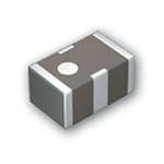
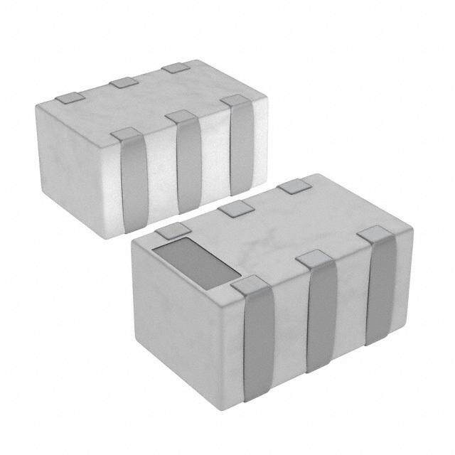
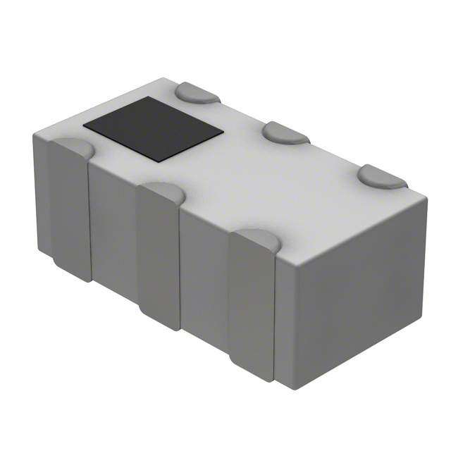
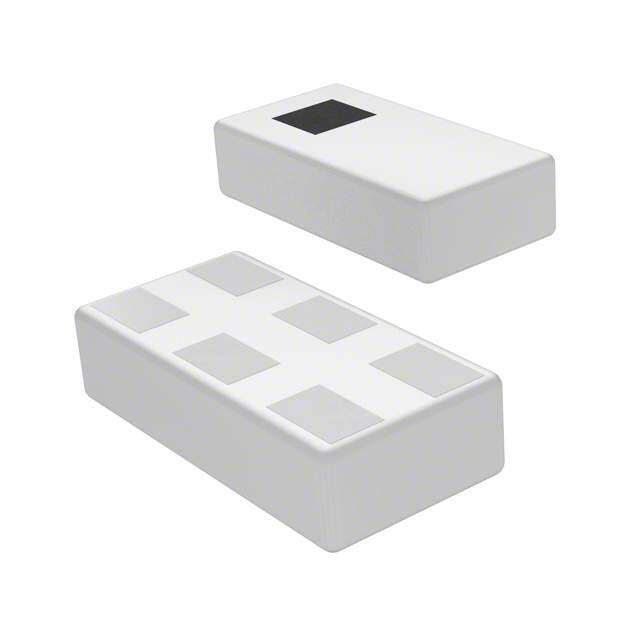
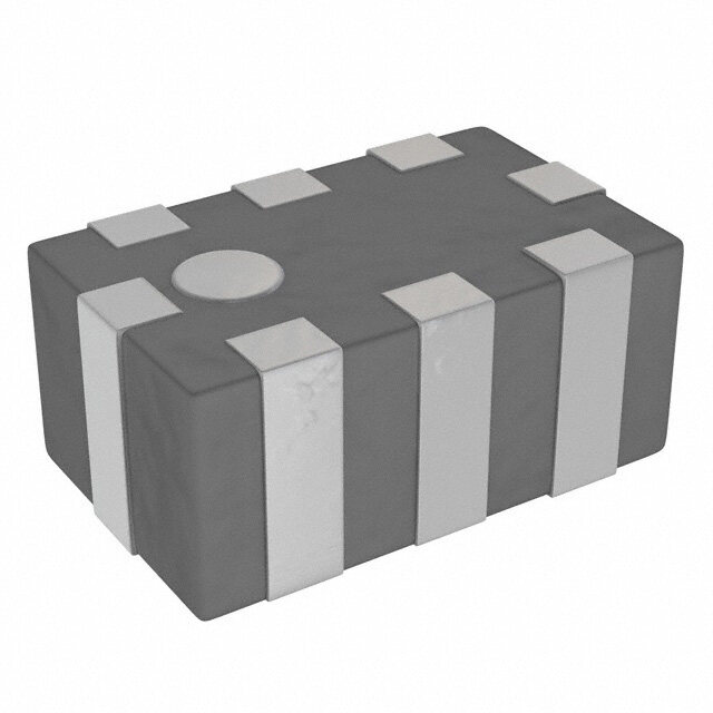
ICGOO电子元器件商城为您提供FI168P245010-T由TAIYO YUDEN-XENTEK设计生产,在icgoo商城现货销售,并且可以通过原厂、代理商等渠道进行代购。 FI168P245010-T价格参考。TAIYO YUDEN-XENTEKFI168P245010-T封装/规格:RF 双工器, RF Diplexor Diplexer 2.4GHz ~ 2.5GHz / 4.9GHz ~ 5.85GHz 0603 (1608 Metric)。您可以下载FI168P245010-T参考资料、Datasheet数据手册功能说明书,资料中有FI168P245010-T 详细功能的应用电路图电压和使用方法及教程。
Taiyo Yuden(太阳诱电)的FI168P245010-T是一款RF双工器,主要用于无线通信系统中实现信号的发送与接收分离。该器件广泛应用于以下场景:

1. 无线基站设备:在蜂窝通信基站(如4G LTE、5G)中,双工器用于隔离发射与接收通道,确保信号互不干扰,FI168P245010-T适用于频分双工(FDD)系统,支持高频段通信。

2. 工业通信设备:用于工业级无线通信模块,如远程监控、工业自动化控制中的无线数据传输系统,提升通信稳定性和抗干扰能力。

3. 物联网(IoT)设备:在需要双向通信的物联网终端中,如智能电表、远程传感器等,实现高效收发信号分离。

4. 车载通信系统:应用于车载无线通信模块,如车载Wi-Fi、车联网(V2X)设备,保障车辆与外界稳定连接。

5. 测试与测量仪器:作为射频测试系统中的关键组件,用于信号路径切换与隔离,提高测试精度。

该双工器具有高隔离度、低插入损耗和良好温度稳定性,适合高频、高性能要求的通信场景。
| 参数 | 数值 |
| 产品目录 | |
| 描述 | DIPLEXER WLAN 2.4GHZ / 4.9GHZ信号调节 DIPLEXER FILTER HI FREQ MULTILAYER |
| 产品分类 | |
| 品牌 | Taiyo Yuden |
| 产品手册 | |
| 产品图片 |
|
| rohs | 符合RoHS无铅 / 符合限制有害物质指令(RoHS)规范要求 |
| 产品系列 | Taiyo Yuden FI168P245010-T- |
| 数据手册 | |
| 产品型号 | FI168P245010-T |
| 产品 | Diplexers |
| 产品种类 | 信号调节 |
| 低频带衰减(最小/最大dB) | 15.00dB / - |
| 其它名称 | 587-3255-1 |
| 包装 | 剪切带 (CT) |
| 商标 | Taiyo Yuden |
| 回波损耗(低频带/高频带) | 9.5dB / 9.5dB |
| 安装类型 | 表面贴装 |
| 封装 | Reel |
| 封装/外壳 | 0603(1608 公制) |
| 封装/箱体 | 1.6 mm x 0.8 mm |
| 工作温度范围 | - 30 C to + 85 C |
| 工厂包装数量 | 4000 |
| 标准包装 | 1 |
| 端接类型 | SMD/SMT |
| 系列 | FI |
| 零件号别名 | 168P245010-T FI PG |
| 频带(低/高) | 2.4GHz ~ 2.5GHz / 4.9GHz ~ 5.85GHz |
| 频率 | 2450 MHz |
| 高频带衰减(最小/最大dB) | 20.00dB / - |


- 商务部:美国ITC正式对集成电路等产品启动337调查
- 曝三星4nm工艺存在良率问题 高通将骁龙8 Gen1或转产台积电
- 太阳诱电将投资9.5亿元在常州建新厂生产MLCC 预计2023年完工
- 英特尔发布欧洲新工厂建设计划 深化IDM 2.0 战略
- 台积电先进制程称霸业界 有大客户加持明年业绩稳了
- 达到5530亿美元!SIA预计今年全球半导体销售额将创下新高
- 英特尔拟将自动驾驶子公司Mobileye上市 估值或超500亿美元
- 三星加码芯片和SET,合并消费电子和移动部门,撤换高东真等 CEO
- 三星电子宣布重大人事变动 还合并消费电子和移动部门
- 海关总署:前11个月进口集成电路产品价值2.52万亿元 增长14.8%


PDF Datasheet 数据手册内容提取
[ For the TAIYO YUDEN Products excluding Notice for TAIYO YUDEN Products Ceramic Capacitors and Inductors ] Please read this notice before using the TAIYO YUDEN products. REMINDERS ■ Product information in this catalog is as of October 2018. All of the contents specified herein are subject to change without notice due to technical improvements, etc. Therefore, please check for the latest information carefully before practical application or use of our products. Please note that TAIYO YUDEN shall not be in any way responsible for any damages and defects in products or equipment incorporating our products, which are caused under the conditions other than those specified in this catalog or individual product specification sheets. ■ Please contact TAIYO YUDEN for further details of product specifications as the individual product specification sheets are available. ■ Please conduct validation and verification of our products in actual condition of mounting and operating environment before using our products. ■ The products listed in this catalog are intended for use in general electronic equipment (e.g., AV equipment, OA equipment, home electric appliances, office equipment, information and communication equipment including, without limitation, mobile phone, and PC). Please be sure to contact TAIYO YUDEN for further information before using the products for any equipment which may directly cause loss of human life or bodily injury (e.g., transportation equipment including, without limitation, automotive powertrain control system, train control system, and ship control system, traffic signal equipment, disaster prevention equipment, medical equipment classified as Class I, II or III by IMDRF, highly public information network equipment including, without limitation, telephone exchange, and base station). Please do not incorporate our products into any equipment requiring high levels of safety and/or reliability (e.g., aerospace equipment, aviation equipment, medical equipment classified as Class IV by IMDRF, nuclear control equipment, undersea equipment, military equipment). When our products are used even for high safety and/or reliability-required devices or circuits of general electronic equipment, it is strongly recommended to perform a thorough safety evaluation prior to use of our products and to install a protection circuit as necessary. Please note that unless you obtain prior written consent of TAIYO YUDEN, TAIYO YUDEN shall not be in any way responsible for any damages incurred by you or third parties arising from use of the products listed in this catalog for any equipment requiring inquiry to TAIYO YUDEN or prohibited for use by TAIYO YUDEN as described above. ■ Information contained in this catalog is intended to convey examples of typical performances and/or applications of our products and is not intended to make any warranty with respect to the intellectual property rights or any other related rights of TAIYO YUDEN or any third parties nor grant any license under such rights. ■ Please note that the scope of warranty for our products is limited to the delivered our products themselves and TAIYO YUDEN shall not be in any way responsible for any damages resulting from a fault or defect in our products. Notwithstanding the foregoing, if there is a written agreement (e.g., supply and purchase agreement, quality assurance agreement) signed by TAIYO YUDEN and your company, TAIYO YUDEN will warrant our products in accordance with such agreement. ■ The contents of this catalog are applicable to our products which are purchased from our sales offices or authorized distributors (hereinafter“ TAIYO YUDEN’s official sales channel”). Please note that the contents of this catalog are not applicable to our products purchased from any seller other than TAIYO YUDEN’s official sales channel. ■ Caution for Export Some of our products listed in this catalog may require specific procedures for export according to“ U.S. Export Administration Regulations”,“ Foreign Exchange and Foreign Trade Control Law” of Japan, and other applicable regulations. Should you have any questions on this matter, please contact our sales staff. 19
MULTILAYER CERAMIC DEVICES / DIPLEXERS / COUPLER / 2 BRANCH COUPLER MULTILAYER CERAMIC DEVICES / DIPLEXERS / COUPLER / 2 BRANCH COUPLER REFLOW REFLOW ■PARTS NUMBER F I △ 2 1 2 B 2 4 5 0 2 6 - T △=Blank space ① ② ③ ④ ⑤ ⑥ ⑦ ① Series name ⑤Frequency Code Series name Code Frequency[MHz] FI High frequency devices (example) 2450 2400~2500 ② Electrode code 0620 470~770 Code Electrode code △ With plating ⑥Spec code Code Spec code ③ Dimensions 01~ Individual spec Code Dimensions[mm] 212 2.0×1.25 ⑦Packaging H 168 1.6×0.8 Code Packaging IG 105 1.0×0.5 -T Taping H F ④ Special code R Code Special code E Q B Band pass type U L Low pass type E H High pass type N C Balance type C Y P Diplexer P W 2 Branch coupler R D Dual type O D K Coupler U C ■EXTERNAL DIMENSIONS / STANDARD QUANTITY T S FI 212B type FI 168B/L type FI 105B/L type FI 168L0628M4 2.0±0.15 0.9±0.10 1.6±0.10 0.5max. 1.00±0.05 0.4max. 1.6±0.10 0.65max. IN GGNNDD OUT1.25±0.15 0.30±0.20 IN GGNNDD OUT0.80±0.10 0.30±0.10 IN GGNNDD OUT0.50±0.05 0.30±0.10 ((16)) ((25)) ((34)) 0.80±0.10 ±0.05 0.50±0.15 0.10 0.10±0.05 1.6±0.20 0.7±0.10 0.30±0.10 0.2±0.10 FI 168L****G* type FI 168H type FI 168D type FI 212C245033 1.6±0.10 0.65max. 1.6±0.10 0.65max. 1.6±0.10 0.45max. 2.0±0.15 0.9±0.10 0.80±0.10 0.80±0.10 ((61)) ((52)) ((43)) 0.80±0.10 (8) ((71)) ((62)) ((53)) (4) 1.25±0.15 0.30±0.20 (1) (2) (3) (1) (2) (3) 0.60±0.10 0.60±0.10 0.60±0.10 0.60±0.10 0.50±0.15 0.65±0.20 (1) (2) (3) ±0.10 (1) (2) (3) ±0.10 0.70 0.70 0.30±0.10 0.30±0.10 0.30±0.10 0.30±0.10 0.40±0.10 0.40±0.10 0.2±0.15 0.3±0.20 FI 212C type FI 212C245075 FI 168P type FI 212P type 2.0±0.15 0.9±0.10 2.0±0.15 0.7max. 1.6±0.10 0.65max. 2.0±0.15 0.9±0.10 (7) (6) (5) (7) (6) (5) (6) (5) (4) (6) (5) (4) (8) (4) ±0.15 ±0.20 (8) (4) ±0.15 ±0.20 ±0.10 ±0.15 (1) (2) (3) 1.25 0.30 (1) (2) (3) 1.25 0.30 (1) (2) (3) 0.80 (1) (2) (3) 1.25 0.65±0.20 0.65±0.20 0.65±0.20 0.2±0.1 0.50±0.15 0.3±0.20 0.3±0.20 0.3±0.20 Unit::mm chipfilter_e-E07R01 ▶ This catalog contains the typical specification only due to the limitation of space. When you consider the purchase of our products, please check our product specification sheets. For details of each product (characteristics graph, reliability information, precautions for use, and so on), see our website (http://www.ty-top.com/) . 148 19
FI 212P****G* type FI 168W type FI168K type 2.0±0.15 0.9±0.10 1.6±0.10 0.5max. 1.6±0.10 0.65max. (1) (2) (3) (6) (5) (4) 1.25±0.15 (8) ((71)) ((62)) ((53)) (4) 0.80±0.10 0.20±0.15 ((61)) ((52)) ((43)) 0.80±0.10 0.65±0.10 0.50±0.15 (6) (5) (4) 0.30±0.10 0.20±0.15 0.50±0.15 (1) (2) (3) 0.05typ 0.2±0.15 0.3±0.10 Unit:mm FI 168L0628M4 FI 168L****G* type FI 168H type FI 168D087018 FI 212C2450** FI 168P245030 (1) I/O Port RF IN/OUT RF IN/OUT High Band IN Balanced GND (2) GND GND GND GND GND Common (3) I/O Port RF IN/OUT RF IN/OUT Low Band IN Balanced GND (4) GND - - Low Band OUT GND Low Band (5) GND - - GND Unbalance GND (6) GND - - High Band OUT DC High Band (7) - - - - NC - H (8) - - - - GND - IG H F FI 212P****G* type FI 212P089208 FI 212P089213 FI 168P157519 FI 168W type FI 168K type R FI 212P085912 FI 212P085909 E Q (1) Low Band GND GND GND RF1 IN/OUT COUPLING U (2) GND Common Port Common Port High Band CPL2 RF1 GND E (3) High Band GND GND Common CPL2 RF2 ISOLATION N (4) GND High Band Low Band Low Band GND RF OUT C Y (5) Common GND GND - RF2 OUT/IN GND P (6) GND Low Band High Band - CPL1 RF2 RF IN R O (7) - - - - CPL1 RF1 - D (8) - - - - GND - U C T S Type Standard quantity[pcs] 212 3000~6000 168 4000~8000 105 10000 chipfilter_e-E07R01 ▶ This catalog contains the typical specification only due to the limitation of space. When you consider the purchase of our products, please check our product specification sheets. For details of each product (characteristics graph, reliability information, precautions for use, and so on), see our website (http://www.ty-top.com/) . 19 149
■PARTS NUMBER ●Multilayer device band pass type Applications External dimensions [mm] Part number 2.0×1.25×1.0max. FI 212B245026 2.0×1.25×1.0max. FI 212B245027 2.4GHz W-LAN / Bluetooth® 1.6×0.8×0.5max. FI 168B245001 1.0×0.5×0.4max. FI 105B245024 ●Multilayer device low pass type Applications External dimensions [mm] Part number Digtal TV 1.6×0.8×0.45max. FI 168L062005 2.4GHz W-LAN / Bluetooth® 1.0×0.5×0.4max. FI 105L250014 1.0×0.5×0.4max. FI 105L186822 1.0×0.5×0.4max. FI 105L087038 Cellular 1.6×0.8×0.65max. FI 168L0628M4 1.6×0.8×0.65max. FI 168L2200G9 1.6×0.8×0.65max. FI 168L1681G6 ●Multilayer device high pass type Applications External dimensions [mm] Part number Cellular 1.6×0.8×0.65max. FI 168H2593GG Applications External dimensions [mm] Part number Notes Other 1.6×0.8×0.45max. FI 168D087018 Dual band LPF ●Multilayer device balance type Applications External dimensions [mm] Part number Notes H Bluetooth® 2.0×1.25×1.0max. FI 212C245033 Conjugated match to CSR BC3 IG 2.0×1.25×1.0max. FI 212C245036 Conjugated match to CSR BC5 H 2.0×1.25×0.7max. FI 212C245075 Conjugated match to CSR BC5FM, BC6ROM F ●Multilayer diplexer R E Applications External dimensions [mm] Part number Q W-LAN 1.6×0.8×0.65max. FI 168P245030 U 2.0×1.25×1.0max. FI 212P082931 E 2.0×1.25×1.0max. FI 212P0829G2 N 2.0×1.25×1.0max. FI 212P082934 C 2.0×1.25×1.0max. FI 212P082935 Y Cellular 2.0×1.25×1.0max. FI 212P089208 P 2.0×1.25×1.0max. FI 212P089213 R 2.0×1.25×1.0max. FI 212P085909 O 2.0×1.25×1.0max. FI 212P085912 D 1.6×0.8×0.65max. FI 168P157519 U GPS / 2.4GHz W-LAN 1.6×0.8×0.65max. FI 168P157525 C T ●Multilayer coupler S Applications External dimensions [mm] Part number 1.6×0.8×0.5max. FI 168W1697B1 Cellular 1.6×0.8×0.5max. FI 168K1687AA chipfilter_e-E07R01 ▶ This catalog contains the typical specification only due to the limitation of space. When you consider the purchase of our products, please check our product specification sheets. For details of each product (characteristics graph, reliability information, precautions for use, and so on), see our website (http://www.ty-top.com/) . 150 19
■ELECTRICAL CHARACTERISTICS / TYPICAL CHARACTERISTICS FI 212B245026 Pass band frequency 2400 - 2500 MHz Insertion loss at pass band 2.6 dB max. (+25℃) 2.9 dB max. (-40~+85℃) Ripple at pass band 1.0 dB max. V.S.W.R. at pass band 2.0 max. Attenuation 40 dB min. (800 - 960 MHz) 30 dB min. (1710 - 1990 MHz) 25 dB min. (2110 - 2170 MHz) 30 dB min. (4800 - 5000 MHz) 30 dB min. (7200 - 7500 MHz) Impedance 50 Ω FI 212B245027 Pass band frequency 2400 - 2500 MHz Insertion loss at pass band 1.4 dB max. (+25℃) 1.7 dB max. (-40~+85℃) Ripple at pass band 1.0 dB max. V.S.W.R. at pass band 2.0 max. Attenuation 30 dB min. (800 - 915 MHz) 30 dB min. (1710 - 1910 MHz) 6 dB min. (2110 - 2170 MHz) 20 dB min. (4800 - 5000 MHz) H FI 168B245001 IG Pass band frequency 2400 - 2500 MHz H Insertion loss at pass band 2.2 dB max. (+25℃) 2.5 dB max. (-30~+85℃) F R Ripple at pass band 1.0 dB max. E V.S.W.R. at pass band 2.1 max. Q Attenuation 25 dB min. (800 - 960 MHz) U 25 dB min. (1710 - 1910 MHz) E 20 dB min. (4800 - 5000 MHz) N 20 dB min. (7200 - 7500 MHz) C Impedance 50 Ω Y P R FI 105B245024 O D Pass band frequency 2400 - 2500 MHz U Insertion loss at pass band 3.0 dB max. (+25℃) 3.3 dB max. (-40~+85℃) C T Ripple at pass band 1.0 dB max. S V.S.W.R. at pass band 2.2 max. Attenuation 25 dB min. (800 - 960 MHz) 22 dB min. (1710 - 1910 MHz) 20 dB min. (4800 - 5000 MHz) 20 dB min. (7200 - 7500 MHz) FI 168L062005 Pass band frequency 470 - 770 MHz Insertion loss at 470 - 600 MHz 1.2 dB max. (+25℃) 1.3 dB max. (-30~+85℃) Insertion loss at 600 - 710 MHz 2.2 dB max. (+25℃) 2.4 dB max. (-30~+85℃) Insertion loss at 710 - 770 MHz 4.0 dB max. (+25℃) 4.4 dB max. (-30~+85℃) Ripple at 470 - 710 MHz 1.4 dB max. V.S.W.R. 2.0 max. (470 - 710 MHz) 2.5 max. (710 - 770 MHz) Attenuation 25 dB min. (888 - 925 MHz) (+25℃) 21 dB min. (888 - 925 MHz) (-30~+85℃) 25 dB min. (940 - 960 MHz) 27 dB min. (1429 - 1453 MHz) 26 dB min. (1920 - 1980 MHz) 26 dB min. (2400 - 2500 MHz) Impedance 50 Ω FI 105L250014 Pass band frequency 2400 - 2500 MHz Insertion loss at 2400 - 2500 MHz 0.45 dB max. (+25℃) 0.55 dB max. (-40~+85℃) V.S.W.R. at 2400 - 2500 MHz 1.7 max. Attenuation 21 dB min. (4800 - 5000 MHz) 21 dB min. (7200 - 7500 MHz) Impedance 50 Ω chipfilter_e-E07R01 ▶ This catalog contains the typical specification only due to the limitation of space. When you consider the purchase of our products, please check our product specification sheets. For details of each product (characteristics graph, reliability information, precautions for use, and so on), see our website (http://www.ty-top.com/) . 19 151
■ELECTRICAL CHARACTERISTICS / TYPICAL CHARACTERISTICS FI 105L186822 Pass band frequency 824 - 915 MHz Insertion loss at 824 - 915 MHz 0.75 dB max. (-30~+85℃) 0 V.S.W.R. at 2400 - 2500 MHz 1.5 max. -10 S11 AImttpeenduaantcioen 252303 ddΩBB mmiinn.. ((21467428 -- 21784350 MMHHzz)) Attenuation[dB]----54320000 S21 -60 1.0 2.0 3.0 4.0 5.0 6.0 7.0 Frequency[GHz] FI 105L087038 Pass band frequency 824 - 915 MHz Insertion loss at 824 - 915 MHz 0.75 dB max. (-30~+85℃) V.S.W.R. at 2400 - 2500 MHz 1.5 max. Attenuation 23 dB min. (1648 - 1830 MHz) 23 dB min. (2472 - 2745 MHz) Impedance 50 Ω H IG FI 168L0628M4 H F PInassesr tbioann dlo fsrse qaut epnacsys band 407.50 d-B 7m87ax M. (H+z25℃) 0 REQUEN RVAi.tSptep.Wlneu. Raa.tt i aoptna psass bsa bnadnd 20-326.0.60 dddmBBBa xmmm.iiannx.. .(( 11(-54462059~ -- +11965000℃71 )MMHHzz)) Attenuation [dB]‐‐‐‐43210000 SS1211 C 35 dB min. (1570 - 1580 MHz) ‐50 Y 18 dB min. (1920 - 1980 MHz) ‐60 P 0.4 0.8 1.2 1.6 2.0 2.4 2.8 R Impedance 50 Ω Frequency [GHz] O D FI 168L2200G9 U Pass band frequency 1700 - 2170 MHz C 2170 - 2500 MHz T 2500 - 2700 MHz S Insertion loss at 1700 - 2170 MHz 0.5 dB max. (+25℃) 0.55 dB max. (-30~+85℃) Insertion loss at 2170 - 2500 MHz 0.65 dB max. (+25℃) 0.75 dB max. (-30~+85℃) Insertion loss at 2500 - 2700 MHz 0.9 dB max. (+25℃) 1.0 dB max. (-30~+85℃) Return loss. at 1700 - 2700 MHz 10 dB min. Attenuation 25 dB min. (3400 MHz) 22 dB min. (3400 - 5400 MHz) 20 dB min. (5400 - 8100 MHz) Impedance 50 Ω FI 168L1681G6 Pass band frequency 617 - 2690 MHz 0 0.5 dB max. (-40~+90℃) Return loss. at 617 - 2690 MHz 10 dB min. -10 S11 S21 Attenuation 33335555 ddddBBBB mmmmiiiinnnn.... ((((6748059100500000 ---- 7861510000050000 0MMM MHHHHzzz)))z) Attenuation[dB] ----54320000 27 dB min. (10500 - 12500 MHz) Impedance 50 Ω -600.51.52.53.54.55.56.57.58.59.510.511.512.5 Frequency[GHz] FI 168H2593GG Pass band frequency 2496 - 2690 MHz Insertion loss at 2500 - 2700 MHz 0.9 dB max. (-40~+90℃) 0 Return loss. at 1700 - 2700 MHz 15 dB min. -10 AImtpteenduaantcioen 2550 dΩB min. (1710 - 1995 MHz) Attenuation[dB] ---432000 S11 S21 -50 0.5 1.5 2.5 3.5 4.5 5.5 6.5 Frequency[GHz] chipfilter_e-E07R01 ▶ This catalog contains the typical specification only due to the limitation of space. When you consider the purchase of our products, please check our product specification sheets. For details of each product (characteristics graph, reliability information, precautions for use, and so on), see our website (http://www.ty-top.com/) . 152 19
■ELECTRICAL CHARACTERISTICS / TYPICAL CHARACTERISTICS FI 168D087018 Low band Pass band frequency 824 - 915 MHz Insertion loss at 824 - 915 MHz 0.6 dB max. (-30~+85℃) V.S.W.R. at 824 - 915 MHz 1.5 max. Attenuation 25 dB min. (1648 - 1830 MHz) 25 dB min. (2472 - 2745 MHz) Impedance 50 Ω High band Pass band frequency 1710 - 1910 MHz Insertion loss at 1710 - 1910 MHz 0.6 dB max. (-30~+85℃) V.S.W.R. at 824 - 915 MHz 1.5 max. Attenuation 25 dB min. (3420 - 3820 MHz) 25 dB min. (5130 - 5730 MHz) Impedance 50 Ω Isolation In to In/Out to Out 27 dB min. (824 - 915 MHz) 30 dB min. (1710 - 1910 MHz) In to Out 30 dB min. (824 - 915 MHz) 30 dB min. (1710 - 1910 MHz) FI 212C245033 Pass band frequency 2400 - 2500 MHz Insertion loss at pass band 2.7 dB (+25℃) 3.0 dB (-30~+85℃) H Ripple at pass band 1.0 dB max. Unbalanced port V.S.W.R. at pass band 2.0 max. IG Balanced port V.S.W.R. at pass band 2.0 max. H Amplitude Imbalance at pass band 2.0 dB max. F Phase Imbalance at pass band 180 ±10℃ R Attenuation 25 dB min. (880 - 960 MHz) E Q 15 dB min. (1710 - 1990 MHz) 15 dB min. (1990 - 2170 MHz) U 15 dB min. (4800 - 5000 MHz) E N Unbalanced port Impedance 50 Ω Balanced port Impedance Conjugated match to CSR BC3 C Y FI 212C245036 P R Pass band frequency 2400 - 2500 MHz O Insertion loss at pass band 3.7 dB (+25℃) D 4.0 dB (-30~+85℃) U Ripple at pass band 1.0 dB max. C Unbalanced port V.S.W.R. at pass band 2.0 max. T Balanced port V.S.W.R. at pass band 2.0 max. S Amplitude Imbalance at pass band 2.0 dB max. Phase Imbalance at pass band 180 ±10℃ Attenuation 35 dB min. (880 - 960 MHz) 20 dB min. (1710 - 1990 MHz) 15 dB min. (1990 - 2170 MHz) 20 dB min. (4800 - 5000 MHz) Unbalanced port Impedance 50 Ω Balanced port Impedance Conjugated match to CSR BC5 FI 212C245075 Pass band frequency 2400 - 2500 MHz Insertion loss at pass band 3.7 dB (+25℃) 4.0 dB (-30~+85℃) Ripple at pass band 1.0 dB max. Unbalanced port V.S.W.R. at pass band 2.2 max. Balanced port V.S.W.R. at pass band 2.2 max. Amplitude Imbalance at pass band 2.0 dB max. Phase Imbalance at pass band 180 ±10℃ Attenuation 40 dB min. (880 - 960 MHz) 18 dB min. (1710 - 1990 MHz) 12 dB min. (1990 - 2170 MHz) 30 dB min. (4800 - 5000 MHz) Unbalanced port Impedance 50 Ω Balanced port Impedance Conjugated match to CSR BC5FM, BC6ROM chipfilter_e-E07R01 ▶ This catalog contains the typical specification only due to the limitation of space. When you consider the purchase of our products, please check our product specification sheets. For details of each product (characteristics graph, reliability information, precautions for use, and so on), see our website (http://www.ty-top.com/) . 19 153
■ELECTRICAL CHARACTERISTICS / TYPICAL CHARACTERISTICS FI 168P245030 Low band Pass band frequency 1 1558 - 1610 MHz Pass band frequency 2 2400 - 2500 MHz 0 IIVAInnm.tssStpeee.eWrrndttu.iiaRooannn.t c iaolleootn ssPssa aastts PPbaaanssssd bbaanndd 12 22520046.0..056 Ω 00ddd BBBdd BB mmm mmiiannxaa.. .xx((44..980000 -- 64090000 MMHHzz)) Attenuation/Return Loss [dB]-----5432100000 CHoigmhm Baonnd Rlo Low Band High band -600 2 4 6 8 10 12 14 16 18 Pass band frequency 4900 - 5950 MHz Frequency. [GHz] Insertion loss at Pass band 0.80 dB max. V.S.W.R. at Pass band 2.0 dB max. Attenuation 32 dB min. (30 - 2700 MHz) Impedance 50Ω FI 212P082931 Low band Pass band frequency 1 698 - 894 MHz Pass band frequency 2 880 - 960 MHz Insertion loss at 698 - 894 MHz 0.50 dB max. (+25℃) 0.60 dB max. (-40~+85℃) Insertion loss at 880 - 960 MHz 0.70 dB max. (+25℃) 0.80 dB max. (-40~+85℃) H V.S.W.R. at 698 - 894 MHz 2.0 max. IG V.S.W.R. at 880 - 960 MHz 2.0 max. H Attenuation 13 dB min. (1420 - 2690 MHz) F Impedance 50Ω R E High band Q Pass band frequency 1 1420 - 1520 MHz U Pass band frequency 2 1560 - 1610 MHz E Pass band frequency 3 1710 - 2170 MHz N Pass band frequency 4 2300 - 2690 MHz C Insertion loss at 1420 - 1520 MHz 0.70 dB max. (+25℃) Y 0.80 dB max. (-40~+85℃) P Insertion loss at 1560 - 1610 MHz 0.50 dB max. (+25℃) R 0.60 dB max. (-40~+85℃) O Insertion loss at 1710 - 2170 MHz 0.50 dB max. (+25℃) D 0.60 dB max. (-40~+85℃) U Insertion loss at 2300 - 2690 MHz 0.50 dB max. (+25℃) C 0.60 dB max. (-40~+85℃) T V.S.W.R. at 1420 - 2690 MHz 2.0 max. S Attenuation 13 dB min. (698 - 960 MHz) Impedance 50Ω FI 212P0829G2 Low band Pass band frequency 698 - 960 MHz Insertion loss at 698 - 960 MHz 0.27 dB max. (+25℃) 0.32 dB max. (-40~+85℃) V.S.W.R. at 698 - 960 MHz 2.0 max. Attenuation 13 dB min. (1710 - 2690 MHz) Impedance 50Ω High band Pass band frequency 1710 - 2690 MHz Insertion loss at 1710 - 2690 MHz 0.45 dB max. (+25℃) 0.55 dB max. (-40~+85℃) V.S.W.R. at 698 - 960 MHz 2.0 max. Attenuation 19 dB min. (698 - 960 MHz) Impedance 50Ω chipfilter_e-E07R01 ▶ This catalog contains the typical specification only due to the limitation of space. When you consider the purchase of our products, please check our product specification sheets. For details of each product (characteristics graph, reliability information, precautions for use, and so on), see our website (http://www.ty-top.com/) . 154 19
■ELECTRICAL CHARACTERISTICS / TYPICAL CHARACTERISTICS FI 212P082934 Low band Pass band frequency 698 - 960 MHz Insertion loss at 698 - 960 MHz 0.50 dB max. (-40~+85℃) V.S.W.R. at 698 - 960 MHz 1.4 max. Attenuation 15 dB min. (1554 - 1580 MHz) 25 dB min. (1710 - 2110 MHz) 25 dB min. (2110 - 2155 MHz) 25 dB min. (2155 - 2690 MHz) 12 dB min. (2155 - 7830 MHz) Impedance 50Ω High band Pass band frequency 1 1710 - 2170 MHz Pass band frequency 2 2500 - 2690 MHz Insertion loss at 1710 - 2170 MHz 0.50 dB max. (-40~+85℃) Insertion loss at 2500 - 2690 MHz 0.55 dB max. (-40~+85℃) V.S.W.R. at 1710 - 2170 MHz 1.4 max. V.S.W.R. at 2500 - 2690 MHz 1.8 max. Attenuation 17 dB min. (0.3 - 960 MHz) Impedance 50Ω FI 212P082935 Low band Pass band frequency 698 - 960 MHz Insertion loss at 698 - 960 MHz 0.50 dB max. (-40~+85℃) H V.S.W.R. at 698 - 960 MHz 1.4 max. Attenuation 15 dB min. (1554 - 1580 MHz) IG 25 dB min. (1710 - 2110 MHz) H 25 dB min. (2110 - 2155 MHz) F 25 dB min. (2155 - 2690 MHz) R 12 dB min. (2155 - 7830 MHz) E Q Impedance 50Ω U High band E N Pass band frequency 1 1710 - 2170 MHz Pass band frequency 2 2500 - 2690 MHz C Y Insertion loss at 1710 - 2170 MHz 0.50 dB max. (-40~+85℃) Insertion loss at 2500 - 2690 MHz 0.55 dB max. (-40~+85℃) P R V.S.W.R. at 1710 - 2170 MHz 1.4 max. O V.S.W.R. at 2500 - 2690 MHz 1.8 max. D Attenuation 17 dB min. (0.3 - 960 MHz) U Impedance 50Ω C T FI 212P089208 S Low band Pass band frequency 698 - 960 MHz Insertion loss at 698 - 960 MHz 0.27 dB max. (+25℃) 0.32 dB max. (-40~+85℃) V.S.W.R. at 698 - 960 MHz 2.0 max. Attenuation 13 dB min. (1710 - 2170 MHz) Impedance 50Ω High band Pass band frequency 1710 - 2170 MHz Insertion loss at 1710 - 2170 MHz 0.45 dB max. (+25℃) 0.55 dB max. (-40~+85℃) V.S.W.R. at 698 - 960 MHz 2.0 max. Attenuation 19 dB min. (698 - 960 MHz) Impedance 50Ω FI 212P089213 Low band Pass band frequency 698 - 960 MHz Insertion loss at 698 - 960 MHz 0.27 dB max. (+25℃) 0.32 dB max. (-40~+85℃) V.S.W.R. at 698 - 960 MHz 2.0 max. Attenuation 13 dB min. (1710 - 2170 MHz) Impedance 50Ω High band Pass band frequency 1710 - 2170 MHz Insertion loss at 1710 - 2170 MHz 0.45 dB max. (+25℃) 0.55 dB max. (-40~+85℃) V.S.W.R. at 698 - 960 MHz 2.0 max. Attenuation 19 dB min. (698 - 960 MHz) Impedance 50Ω chipfilter_e-E07R01 ▶ This catalog contains the typical specification only due to the limitation of space. When you consider the purchase of our products, please check our product specification sheets. For details of each product (characteristics graph, reliability information, precautions for use, and so on), see our website (http://www.ty-top.com/) . 19 155
■ELECTRICAL CHARACTERISTICS / TYPICAL CHARACTERISTICS FI 212P085909 Low band Pass band frequency 698 - 960 MHz Insertion loss at 698 - 960 MHz 0.70 dB max. (+25℃) 0.75 dB max. (-30~+85℃) V.S.W.R. at 698 - 960 MHz 1.6 max. Attenuation 19 dB min. (1558 - 1570 MHz) 20 dB min. (1570 - 1580 MHz) 19 dB min. (1580 - 1610 MHz) Impedance 50Ω High band Pass band frequency 1 1558 - 1570 MHz Pass band frequency 2 1570 - 1580 MHz Pass band frequency 3 1580 - 1610 MHz Insertion loss at 1558 - 1570 MHz 0.75 dB max. (+25℃) 0.85 dB max. (-30~+85℃) Insertion loss at 1570 - 1580 MHz 0.70 dB max. (+25℃) 0.80 dB max. (-30~+85℃) Insertion loss at 1580 - 1610 MHz 0.70 dB max. (+25℃) 0.80 dB max. (-30~+85℃) V.S.W.R. at 1558 - 1570 MHz 1.6 max. V.S.W.R. at 1570 - 1580 MHz 1.6 max. V.S.W.R. at 1580 - 1610 MHz 1.6 max. Attenuation 35 dB min. (698 - 824 MHz) 42 dB min. (824 - 894 MHz) H 25 dB min. (894 - 960 MHz) IG Impedance 50Ω H FI 212P085912 F R Low band E Pass band frequency 698 - 960 MHz Q Insertion loss at 698 - 960 MHz 0.70 dB max. (+25℃) U 0.75 dB max. (-30~+85℃) E V.S.W.R. at 698 - 960 MHz 1.6 max. N Attenuation 19 dB min. (1558 - 1570 MHz) C 20 dB min. (1570 - 1580 MHz) Y 19 dB min. (1580 - 1610 MHz) P Impedance 50Ω R O High band D Pass band frequency 1 1558 - 1570 MHz U Pass band frequency 2 1570 - 1580 MHz C Pass band frequency 3 1580 - 1610 MHz T Insertion loss at 1558 - 1570 MHz 0.75 dB max. (+25℃) S 0.85 dB max. (-30~+85℃) Insertion loss at 1570 - 1580 MHz 0.70 dB max. (+25℃) 0.80 dB max. (-30~+85℃) Insertion loss at 1580 - 1610 MHz 0.70 dB max. (+25℃) 0.80 dB max. (-30~+85℃) V.S.W.R. at 1558 - 1570 MHz 1.6 max. V.S.W.R. at 1570 - 1580 MHz 1.6 max. V.S.W.R. at 1580 - 1610 MHz 1.6 max. Attenuation 35 dB min. (698 - 824 MHz) 42 dB min. (824 - 894 MHz) 25 dB min. (894 - 960 MHz) Impedance 50Ω FI 168P157519 Low band Pass band frequency 0 824 - 960 MHz Pass band frequency 1 1558 - 1585 MHz Pass band frequency 2 1585 - 1610 MHz Insertion loss at 824 - 960 MHz 0.50 dB max. (+25℃) 0.60 dB max. (-40~+85℃) Insertion loss at 1558 - 1585 MHz 0.40 dB max. (+25℃) 0.50 dB max. (-40~+85℃) Insertion loss at 1585 - 1610 MHz 0.45 dB max. (+25℃) 0.55 dB max. (-40~+85℃) V.S.W.R. at 824 - 960 MHz 2.0 max. V.S.W.R. at 1558 - 1585 MHz 2.0 max. V.S.W.R. at 1585 - 1610 MHz 2.0 max. Attenuation 13 dB min. (2400 - 2500 MHz) Impedance 50Ω High band Pass band frequency 2400 - 2500 MHz Insertion loss at 2400 - 2500 MHz 0.60 dB max. (+25℃) 0.70 dB max. (-40~+85℃) V.S.W.R. at 2400 - 2500 MHz 2.0 max. Attenuation 12 dB min. (824 - 960 MHz) 23 dB min. (1558 - 1585 MHz) 20 dB min. (1585 - 1610 MHz) Impedance 50Ω chipfilter_e-E07R01 ▶ This catalog contains the typical specification only due to the limitation of space. When you consider the purchase of our products, please check our product specification sheets. For details of each product (characteristics graph, reliability information, precautions for use, and so on), see our website (http://www.ty-top.com/) . 156 19
■ELECTRICAL CHARACTERISTICS / TYPICAL CHARACTERISTICS FI 168P157525 Low band Pass band frequency 0 824 - 960 MHz Pass band frequency 1 1558 - 1585 MHz Pass band frequency 2 1585 - 1610 MHz Insertion loss at 824 - 960 MHz 0.50 dB max. (+25℃) 0.60 dB max. (-40~+85℃) Insertion loss at 1558 - 1585 MHz 0.40 dB max. (+25℃) 0.50 dB max. (-40~+85℃) Insertion loss at 1585 - 1610 MHz 0.45 dB max. (+25℃) 0.55 dB max. (-40~+85℃) V.S.W.R. at 824 - 960 MHz 2.0 max. V.S.W.R. at 1558 - 1585 MHz 2.0 max. V.S.W.R. at 1585 - 1610 MHz 2.0 max. Attenuation 13 dB min. (2400 - 2500 MHz) Impedance 50Ω High band Pass band frequency 2400 - 2500 MHz Insertion loss at 2400 - 2500 MHz 0.60 dB max. (+25℃) 0.70 dB max. (-40~+85℃) V.S.W.R. at 2400 - 2500 MHz 2.0 max. Attenuation 12 dB min. (824 - 960 MHz) 23 dB min. (1558 - 1585 MHz) 12 dB min. (1585 - 1610 MHz) Impedance 50Ω H FI 168W1697B1 IG Pass band frequency 699 - 2690 MHz H Insertion loss at 699 - 960 MHz 0.15 dB max. (+35~+85℃) F 0.1 dB max. (+15~+35℃) R 0.1 dB max. (-20~+15℃) E Q Insertion loss at 1000 - 2025 MHz 0.25 dB max. (+35~+85℃) 0.2 dB max. (+15~+35℃) U 0.2 dB max. (-20~+15℃) E N Insertion loss at 2110 - 2690 MHz 0.38 dB max. (+35~+85℃) 0.28 dB max. (+15~+35℃) C Y 0.28 dB max. (-20~+15℃) Ripple 0.1 dB max. (699 - 746 MHz) P 0.1 dB max. (791 - 862 MHz) R O 0.1 dB max. (824 - 960 MHz) D 0.1 dB max. (1710 - 2170 MHz) U 0.1 dB max. (2500 - 2690 MHz) RF Coupling 28.1~29.5 dB (699MHz) C T 25.8~27.2 dB (915MHz) S 20.7~22.1 dB (1710MHz) 19.9~21.3 dB (1880MHz) 19.3~20.7 dB (2025MHz) 18.3~19.7 dB (2300MHz) 17.1~18.5 dB (2690MHz) Coupling ration missmatch between Coupler -1~1 dB (699 - 2690 MHz) branch 1 and Coupler branch 2 Directivity 18 dB min. (699 - 2690 MHz) Impedance 50 Ω FI 168K1687AA Pass band frequency 698 - 2690 MHz 0 Insertion loss at 699 - 2690 MHz 0.25 dB max. (+25℃) CPL 0.30 dB max. (-40~+85℃) -10 ISO SR1F1 C Coouupplinlegd port at 698 - 2690 MHz 022222.411162.....505555 ~~~~~dB22222 44479m.....55500a xddddd.BBBBB ( +(((((212296570319℃12085M050M)MMMHHHHHzz))zzz))) Couple/Isolation[dB]----54320000 0.5 1.0 1.5 2.0 2.5 3.0 21.5~25.5 dB (2690MHz) Frequency[GHz] Isolation 35 dB min. (698 - 2690 MHz) Impedance 50 Ω chipfilter_e-E07R01 ▶ This catalog contains the typical specification only due to the limitation of space. When you consider the purchase of our products, please check our product specification sheets. For details of each product (characteristics graph, reliability information, precautions for use, and so on), see our website (http://www.ty-top.com/) . 19 157
MULTILAYER CERAMIC DEVICES / DIPLEXERS / COUPLER / 2 BRANCH COUPLER ■PACKAGING ①Minimum Quantity Type Embossed tape / Paper tape [pcs] 212B 212C 3000 212P 168B 168L 4000 168D 168P 168L-G 5000 168H 168W 8000 168K 105B 10000 105L ②Tape Material ●Embossed Tape ●Card Board Cattier Tape Top tape Top tape Base tape Sprocket hole Sprocket hole Base tape Chip cavity Bottom tape Chip cavity Chip Filled Chip ●Taped package Thickness Type Standard Quantity [pcs] mm (inch) 212B 0.90 typ.(0.035) 212C 0.90 typ.(0.035) 3000 212P 0.90 typ.(0.035) 212C-0.7 0.60 typ.(0.024) 168B 0.45 typ.(0.018) 168L-0.5 0.45 typ.(0.018) 168L-0.65 0.60 typ.(0.024) 4000 168D 0.45 typ.(0.018) 168P 0.60 typ.(0.024) 168L-G 0.60 typ.(0.024) 5000 168H 0.60 typ.(0.024) 168W 0.45 typ.(0.018) 8000 168K 0.60 typ.(0.024) 105B 0.30 typ.(0.0118) 10000 105L 0.30 typ.(0.0118) ▶ This catalog contains the typical specification only due to the limitation of space. When you consider the purchase of our products, please check our specification. For details of each product (characteristics graph, reliability information, precautions for use, and so on), see our Web site (http://www.ty-top.com/) . chipfilter_pack_e-E07R01
③Taping Dimensions ●Embossed tape 0.315 inches wide φ1.5+0.1/-0 1.75±0.1 Sprockethole (φ0.059+0.004/-0) (0.069±0.004) A B 3.5±0.05(0.138±0.002) 8.0±0.30.315±0.012) ( F 4.0±0.1 (0.157±0.004) 2.0±0.05 (0.079±0.002) Unit:mm(inch) Chip cavity Insertion Pitch Tape Thickness max. Type A B F K T 1.55±0.2 2.3±0.2 4.0±0.1 1.6 0.3 212B (0.061±0.008) (0.091±0.008) (0.157±0.004) (0.063) (0.012) 1.55±0.2 2.3±0.2 4.0±0.1 1.6 0.3 212C (0.061±0.008) (0.091±0.008) (0.157±0.004) (0.063) (0.012) 1.55±0.2 2.3±0.2 4.0±0.1 1.3 0.3 212C-0.7 (0.061±0.008) (0.091±0.008) (0.157±0.004) (0.051) (0.012) 1.55±0.2 2.3±0.2 4.0±0.1 1.6 0.3 212P (0.061±0.008) (0.091±0.008) (0.157±0.004) (0.063) (0.012) Unit:mm(inch) ●Paper tape 0.315 inches wide φ1.5+0.1/-0 1.75±0.1 Sprockethole (φ0.059+0.004/-0) (0.069±0.004) T A B 3.5±0.05(0.138±0.002) 8.0±0.30.315±0.012) ( F 4.0±0.1 (0.157±0.004) 2.0±0.05 (0.079±0.002) Unit:mm(inch) Chip cavity Insertion Pitch Tape Thickness max. Type A B F T 1.00±0.05 1.80±0.05 4.0±0.1 0.55 168B (0.039±0.002) (0.071±0.002) (0.157±0.004) (0.022) 1.00±0.05 1.80±0.05 4.0±0.1 0.55 168L (0.039±0.002) (0.071±0.002) (0.157±0.004) (0.022) 1.00±0.05 1.80±0.05 4.0±0.1 0.55 168W (0.039±0.002) (0.071±0.002) (0.157±0.004) (0.022) 1.00±0.05 1.80±0.05 4.0±0.1 0.80 168K (0.039±0.002) (0.071±0.002) (0.157±0.004) (0.031) 1.00±0.05 1.80±0.05 4.0±0.1 0.55 168D (0.039±0.002) (0.071±0.002) (0.157±0.004) (0.022) 0.95±0.05 1.80±0.05 4.0±0.1 0.80 168P (0.037±0.002) (0.071±0.002) (0.157±0.004) (0.031) 0.95±0.05 1.80±0.05 4.0±0.1 0.80 168L-G (0.037±0.002) (0.071±0.002) (0.157±0.004) (0.031) 0.95±0.05 1.80±0.05 4.0±0.1 0.80 168H (0.037±0.002) (0.071±0.002) (0.157±0.004) (0.031) 0.62±0.03 1.12±0.03 2.0±0.05 0.45 105B (0.024±0.001) (0.044±0.001) (0.079±0.002) (0.018) 0.62±0.03 1.12±0.03 2.0±0.05 0.45 105L (0.024±0.001) (0.044±0.001) (0.079±0.002) (0.018) Unit:mm(inch) ▶ This catalog contains the typical specification only due to the limitation of space. When you consider the purchase of our products, please check our specification. For details of each product (characteristics graph, reliability information, precautions for use, and so on), see our Web site (http://www.ty-top.com/) . chipfilter_pack_e-E07R01
④Leader and Blank Portion ⑤Reel size t E C B A R D W A B C D E R φ178±2.0 φ50min. φ13.0±0.2 φ21.0±0.8 2.0±0.5 1.0 (φ7.01±0.079) (φ1.97 min.) (φ0.512±0.008) (φ0.827±0.031) (0.079±0.020) t W 8mm width tape 2.5max. 10±1.5 (0.315 inches width) (0.098max.) (0.394±0.059) 12mm width tape 2.5max. 14±1.5 (0.472 inches width) (0.098max.) (0.551±0.059) Unit:mm(inch) ⑥Top Tape Strength The top tape requires a peel-off force of 0.1~0.7N in the direction of the arrow as illustrated below. ▶ This catalog contains the typical specification only due to the limitation of space. When you consider the purchase of our products, please check our specification. For details of each product (characteristics graph, reliability information, precautions for use, and so on), see our Web site (http://www.ty-top.com/) . chipfilter_pack_e-E07R01
MULTILAYER CERAMIC DEVICES / DIPLEXERS / COUPLER / 2 BRANCH COUPLER ■RELIABILITY DATA 1. Operating Temperature Range Specified Value -30~+85℃ 2. Storage Temperature Range Specified Value -30~+85℃ Test Methods and ※Note : -20 to +40℃ in taped packaging Remarks 3. Resistance to Flexure of Substrate Specified Value No mechanical damage. Warp : 2mm Testing board : Glass epoxy-resin substrate Thickness : 0.8mm Test Methods and Remarks 4. Adhesion of Electrode Characteristics : shall satisfy the electrical characteristics. Specified Value Appearance : No significant abnormality. Applied force : 5N Duration : 10 sec. Test Methods and Remarks 5. Solderability Specified Value 75% or more of immersed surface of terminal electrode shall be covered with fresh solder. Solder temperature : 230±5℃ Test Methods and Duration : 4±1 sec Remarks Preconditioning : Immersion into flux. Immersion and Removal speed : 25mm/sec. 6. Resistance to Solder Heat Characteristics : shall satisfy the electrical characteristics. Specified Value Appearance : No significant abnormality. Preheating : 150℃ for 2 min. Solder temperature : 260±5℃ Test Methods and Duration : 5±0.5 sec. Remarks Preconditioning : Immersion into flux. Immersion and Removal speed : 25mm/sec. Recovery : 2 to 3hrs of recovery under the standard condition after the removal from test chamber. ▶ This catalog contains the typical specification only due to the limitation of space. When you consider the purchase of our products, please check our specification. For details of each product (characteristics graph, reliability information, precautions for use, and so on), see our Web site (http://www.ty-top.com/) . chipfilter_reli_e-E07R01
7. Thermal Shock Characteristics : shall satisfy the electrical characteristics. Specified Value Appearance : No significant abnormality. According to JIS C60068-2-14. Conditions for 1 cycle Step Temperature (℃) Duration (min) 1 -40±3 30±3 2 Room Temperature Within 3 Test Methods and 3 85±2 30±3 Remarks 4 Room Temperature Within 3 Number of cycles : 100 Mounting method : Soldering onto PC board. Recovery : 2 to 3hrs of recovery under the standard condition after the removal from test chamber. 8. Humidity (steady state) Characteristics : shall satisfy the electrical characteristics. Specified Value Appearance : No significant abnormality. Temperature : +40±2℃ Test Methods and Humidity : 90~95%RH Remarks Duration : 96hrs Recovery : 2 to 3hrs of recovery under the standard condition after the removal from test chamber. 9. High temperature life test Characteristics : shall satisfy the electrical characteristics. Specified Value Appearance : No significant abnormality. Temperature : +85±2℃ Test Methods and Duration : 96hrs Remarks Recovery : 2 to 3hrs of recovery under the standard condition after the removal from test chamber. 10. Low temperature life test Characteristics : shall satisfy the electrical characteristics. Specified Value Appearance : No significant abnormality. Temperature : -40±2℃ Test Methods and Duration : 96hrs Remarks Recovery : 2 to 3hrs of recovery under the standard condition after the removal from test chamber. Note on standard condition: "standard condition" referred to herein is defined as follows : 5 to 35℃ of temperature, 45 to 85% relative humidity and 86 to 106kPa of air pressure. When there are questions concerning measurement result : In order to provide correlation data, the test shall be conducted under condition of 20±2℃ of temperature, 60 to 70% relative humidity and 86 to 106kPa of air pressure. Unless otherwise specified, all the tests are conducted under the "standard condition". ▶ This catalog contains the typical specification only due to the limitation of space. When you consider the purchase of our products, please check our specification. For details of each product (characteristics graph, reliability information, precautions for use, and so on), see our Web site (http://www.ty-top.com/) . chipfilter_reli_e-E07R01
MULTILAYER CERAMIC DEVICES / DIPLEXERS / COUPLER / 2 BRANCH COUPLER ■PRECAUTIONS 1. PCB Design ◆Land pattern design Land pattern dimension examples FI212B Type FI168B/L Type FI105B/L Type FI168L/H LGA Type 0.60 0.25 0.25 0.40 0.25 0.25 Unit:mm Unit:mm Unit:mm Unit:mm FI168D/FI168K Type FI212C Type FI168P Type FI212P Type Technical considerations Unit:mm Unit:mm Unit:mm Unit:mm FI212P****G* Type FI168W Type 0.6500 0.3500 0.3500 0.5000 Unit:mm Unit:mm 2. Soldering ◆Conditions for Reflow soldering (for reference) 【Reflow Profile】 300 300 Preheating 230℃ Peak Within 10sec. 260℃ Max. ℃) 200 60Msine.c . 6M0sine.c ℃) 200 Within 10sec. conTseicdhenraictaiol ns Temperature( 100 Slow cooling Temperature( 100 cSoololiwn g ※※ No tAetCo so: s1mTu3hpr0eeo℃d na e btnofotr vsobe mes ph rsreooofullfoldidlwee rsb is enao grpl edtr eeetrmhhineepga em trfeaoadtxr u it2mro eut .wi mmi tehsi.n 100 Preheating150℃ Heating above allowable soldering condition, therefore 60sec. Min. 230℃ these profiles are not always 0 0 40sec. Max. recommended. ▶ This catalog contains the typical specification only due to the limitation of space. When you consider the purchase of our products, please check our specification. For details of each product (characteristics graph, reliability information, precautions for use, and so on), see our Web site (http://www.ty-top.com/) . chipfilter_prec_e-E07R01
3. Storage conditions ◆Storage 1. To maintain the solderability of terminal electrodes and to keep the packaging material in good condition, care must be taken to control temperature and humidity in the storage area. Humidity should especially be kept as low as possible. ・ Recommended conditions Ambient temperature : -20~+40℃ Precautions Humidity : Below 70%RH The ambient temperature must be kept below 30℃. Even under ideal storage conditions, the solderbility of electrodes decreases gradually, so filters should be mounted within 6 months from the time of delivery. ・ The packaging material should be kept where no chlorine or sulfur exists in the air. ◆Storage Technical 1. If the parts are stocked in a high temperature and humidity environment, problems such as reduced solderability caused by oxidation of considerations terminal electrodes and deterioration of taping/ packaging materials may take place. For this reason, components should be used within 6 months from the time of delivery. If exceeding the above period, please check the solderability before using the filter. ■ Please contact of our offices for further details of specifications. All of the standard values listed here are subject to change without notice. Therefore, please check the specifications carefully before use. ▶ This catalog contains the typical specification only due to the limitation of space. When you consider the purchase of our products, please check our specification. For details of each product (characteristics graph, reliability information, precautions for use, and so on), see our Web site (http://www.ty-top.com/) . chipfilter_prec_e-E07R01