ICGOO在线商城 > F1778368K2FCB0

 Datasheet下载
- 型号: F1778368K2FCB0
- 制造商: Vishay
- 库位|库存: xxxx|xxxx
- 要求:
| 数量阶梯 | 香港交货 | 国内含税 |
| +xxxx | $xxxx | ¥xxxx |
查看当月历史价格
查看今年历史价格
F1778368K2FCB0产品简介:
ICGOO电子元器件商城为您提供F1778368K2FCB0由Vishay设计生产,在icgoo商城现货销售,并且可以通过原厂、代理商等渠道进行代购。 提供F1778368K2FCB0价格参考以及VishayF1778368K2FCB0封装/规格参数等产品信息。 你可以下载F1778368K2FCB0参考资料、Datasheet数据手册功能说明书, 资料中有F1778368K2FCB0详细功能的应用电路图电压和使用方法及教程。
Vishay BC Components 的薄膜电容器型号 F1778368K2FCB0 主要应用于高可靠性、高性能的电子系统中。该电容器采用聚丙烯薄膜介质,具备低介电损耗、高绝缘电阻和优异的长期稳定性,适用于需要精确信号处理和稳定电容值的场合。典型应用场景包括工业电源滤波、电机驱动电路中的EMI抑制、不间断电源(UPS)、风能与太阳能逆变器等新能源设备中的直流链路支撑与滤波。此外,该器件也常用于医疗电子设备、测试测量仪器以及铁路牵引系统等对安全性和耐久性要求较高的领域。F1778368K2FCB0 具备良好的自愈特性,可在高脉冲电流和高温环境下稳定工作,增强了系统可靠性。其符合RoHS标准,适合无铅焊接工艺,广泛用于自动化生产设备中。总之,该型号适用于对电气性能和可靠性有严苛要求的工业与能源类应用。
| 参数 | 数值 |
| 品牌 | Vishay / Roederstein |
| 产品目录 | 无源元件 |
| 描述 | 薄膜电容器 .068UF 275VAC 10% |
| 产品分类 | |
| 产品手册 | |
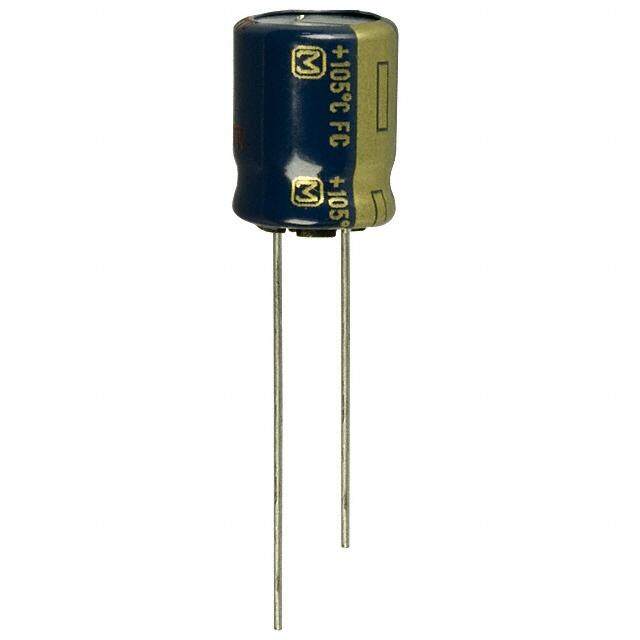
| 产品图片 |
|
| rohs | 符合RoHS |
| 产品系列 | 薄膜电容器,Vishay / Roederstein F1778368K2FCB0 |
| 产品型号 | F1778368K2FCB0 |
| 产品 | Suppression Film Capacitors |
| 产品种类 | |
| 商标 | Vishay / Roederstein |
| 外壳宽度 | 5.3 mm |
| 外壳长度 | 17.8 mm |
| 外壳高度 | 10.3 mm |
| 容差 | 10 % |
| 封装/箱体 | 1778 |
| 引线间隔 | 15 mm |
| 电介质 | Polypropylene (PP) |
| 电压额定值AC | 210 V |
| 电压额定值DC | 630 V |
| 电容 | 0.068 uF |
| 端接类型 | Radial |
| 类型 | Film Capacitors |
| 系列 | F1778X2 |


- 商务部:美国ITC正式对集成电路等产品启动337调查
- 曝三星4nm工艺存在良率问题 高通将骁龙8 Gen1或转产台积电
- 太阳诱电将投资9.5亿元在常州建新厂生产MLCC 预计2023年完工
- 英特尔发布欧洲新工厂建设计划 深化IDM 2.0 战略
- 台积电先进制程称霸业界 有大客户加持明年业绩稳了
- 达到5530亿美元!SIA预计今年全球半导体销售额将创下新高
- 英特尔拟将自动驾驶子公司Mobileye上市 估值或超500亿美元
- 三星加码芯片和SET,合并消费电子和移动部门,撤换高东真等 CEO
- 三星电子宣布重大人事变动 还合并消费电子和移动部门
- 海关总署:前11个月进口集成电路产品价值2.52万亿元 增长14.8%

-20DS-0.5V(57).jpg)

PDF Datasheet 数据手册内容提取
F1778X2 www.vishay.com Vishay Roederstein Interference Suppression Film Capacitor - Class X2 Radial MKP 310 V - Standard Across the Line AC FEATURES • 7.5 mm to 27.5 mm lead pitch • Self-healing properties • For temperature up to 110 °C • Material categorization: for definitions of compliance please see www.vishay.com/doc?99912 APPLICATIONS For standard across the line X2 applications. See also application note: www.vishay.com/doc?28153 QUICK REFERENCE DATA 0.001 μF to 4.7 μF Capacitance range (E12 series) (preferred values acc. to E6) Capacitance tolerance ± 20 %; ± 10 %; (± 5 % on request) Rated AC voltage 310 V ; 50 Hz to 60 Hz AC 800 V at 85 °C Permissible DC voltage DC 630 V at 110 °C DC 55 / 110 / 56 / B for volumes > 1750 mm3 Climatic testing class according to IEC 60068-1 55 / 110 / 56 / C for volumes 1750 mm3 C 470 nF: 110 °C (125 °C for less than 1000 h) Maximum application temperature C > 470 nF: 110 °C IEC 60384-14 ed-4 (2013) and EN 60384-14 IEC 60065, pass. flamm. class B for volumes > 1750 mm3 Reference standards CSA-E384-14; CQC UL 60384-14 Dielectric Polypropylene film Electrodes Metallized film Mono construction Construction Encapsulation Plastic case, epoxy resin sealed, flame retardant class UL 94 V-0 Leads Tinned wire C-value; tolerance; rated voltage; sub-class; manufacturer’s type; Marking code for dielectric material; manufacturer location, year and week; manufacturer’s logo or name; safety approvals Notes • For more detailed data and test requirements, contact rfi@vishay.com DIMENSIONS in millimeters l w h l t P Ø dt Revision: 17-Jan-17 1 Document Number: 27610 For technical questions, contact: rfi@vishay.com THIS DOCUMENT IS SUBJECT TO CHANGE WITHOUT NOTICE. THE PRODUCTS DESCRIBED HEREIN AND THIS DOCUMENT ARE SUBJECT TO SPECIFIC DISCLAIMERS, SET FORTH AT www.vishay.com/doc?91000
F1778X2 www.vishay.com Vishay Roederstein COMPOSITION OF CATALOG NUMBER The new RFI Film Capacitor Code is made up 14 digit code (example) CAPACITANCE CAPACITANCE PITCH SERIES TOLERANCE MULTIPLIER AND DESIGN LEAD VOLTAGES CAPACITANCE CONFIGURATION (NUMERICALLY) POSITION 12, 13, 14 1 2 3 4 5 6 7 8 9 10 11 12 13 14 F 1 7 7 8 4 1 0 M 2 F C B 0 1 2 3 4 5 6 7 8 9 10 11 12 13 14 (POS.) F 1 7 7 8 4 1 0 M 2 F C B 0 Rated Capacitance Capacitance Capacitance Voltage or Design (lead configuration) Value Pitch Series Tolerance special Pos. 12/13/14 expressed in pF versions Pos. 1 to 5 Pos. 6/7/8 Pos. 9 Pos. 10 Pos. 11 Pos. 12 Pos. 13 Pos. 14 represent e.g. 0 (zero) = e.g. 0 (zero) = e.g. 0 (zero) = e.g. 0 (zero) = Packaging of specialities Special internal significant spaceholder spaceholder spaceholder spaceholder 0 (zero) = spaceholder code figures C = 7.5 mm S = 3.5 - 0.5 mm B = bulk/loose 0 (zero) = M = ± 20 % 2 = 310 V D = 10.0 mm P = 3.5 ± 0.3 mm T = tray/pallet (2) spaceholder AC Pos. 6 specifies K = ± 10 % 3 = 310 V F = 15.0 mm B = 4 - 1 mm U = tape and reel (1) other = special AC multiplier (in 10) J = ± 5 % I = 22.5 mm M = 5 - 1 mm (H: 16.5 mm, Ø 350 mm) version K = 27.5 mm C = 6 - 1 mm R = tape and reel (1) e.g.: Specials: E = 10 - 1 mm (H: 16.5 mm, Ø 500 mm) 0.01 µF = 310 A = + 10 %/- 0 % T = 11 - 1 mm V = tape and reel (1) 0.1 µF = 410 B = + 5 %/+ 15 % D = 15 - 1 mm (H: 18.5 mm, Ø 350 mm) 1.0 µF = 510 P = + 0 %/- 15 % F = 19 - 1 mm W = tape and reel (1) R = + 10 %/- 5 % H = 20 + 5 mm (H: 18.5 mm, Ø 500 mm) U = + 10 %/+ 20 % L = 30 + 5 mm G = Ammopack (1) K = 40 + 5 mm (H: 18.5 mm) N = 45 - 2 mm Z = leaded wound other = special element version (unencapsulated) other = special version Notes (1) For detailed tape specification refer to packaging information: www.vishay.com/doc?28139 (2) Packaging will be bulk for all capacitors with pitch 15 mm and such with long leads (> 5 mm). Capacitors with short leads up to 5 mm and pitch > 15 mm will be in tray and asking code will be “T”. Revision: 17-Jan-17 2 Document Number: 27610 For technical questions, contact: rfi@vishay.com THIS DOCUMENT IS SUBJECT TO CHANGE WITHOUT NOTICE. THE PRODUCTS DESCRIBED HEREIN AND THIS DOCUMENT ARE SUBJECT TO SPECIFIC DISCLAIMERS, SET FORTH AT www.vishay.com/doc?91000
F1778X2 www.vishay.com Vishay Roederstein SPECIFIC REFERENCE DATA DESCRIPTION VALUE Rated AC voltage (U ) 310 V RAC Permissible DC voltage (U ) 630 V RDC Tangent of loss angle: at 1 kHz at 10 kHz C 470 nF 10 x 10-4 20 x 10-4 470 nF C 1 μF 20 x 10-4 70 x 10-4 C > 1 μF 30 x 10-4 - Rated voltage pulse slope (dU/dt) at 435 V R DC Pitch = 7.5 mm 600 V/μs Pitch = 10 mm 600 V/μs Pitch = 15 mm 400 V/μs Pitch = 22.5 mm 150 V/μs Pitch = 27.5 mm 100 V/μs R between leads, for C 0.33 μF at 100 V; 1 min 15 000 M RC between leads, for C > 0.33 μF at 100 V; 1 min > 5000 s R between leads and case; 100 V; 1 min 30 000 M Withstanding (DC) voltage (cut off current 10 mA) (1); rise time 1000 V/s: C 1 μF 2200 V; 1 min C > 1 μF 1800 V; 1 min Withstanding (AC) voltage between leads and case 2120 V; 1 min Max. application temperature for 0.001 μF C 0.47 μF 110 °C (125 °C less than 1000 h) Max. application temperature for C > 0.47 μF 110 °C Note (1) See “Voltage Proof Test for Metallized Film Capacitors”: www.vishay.com/doc?28169 ELECTRICAL DATA AND ORDERING CODE TOLERANCE ORDERING CODE (2) CODE DIMENSIONS SPQ (4) CAP. LEAD U POS. 9 MAX. MASS SHORT RAC μF TYPE C-VALUE TOL. VOLTAGE PITCH LENGTH (V) J = ± 5 % w x h x l (g) (3) LEADS POS. 6 TO 8 DESIGN K = ± 10 % (mm) (PIECES) M = ± 20 % 1 TO 5 6 TO 8 9 10 11 12 TO 14 (1) PITCH 7.5 mm ± 0.4 mm; d = 0.50 mm ± 0.05 mm t 0.0010 K / M 4.0 x 9.0 x 10.0 0.45 1500 F1778 210 . . C . . 0 0.0012 K 4.0 x 9.0 x 10.0 0.45 1500 F1778 212 K . C . . 0 0.0015 K / M 4.0 x 9.0 x 10.0 0.45 1500 F1778 215 . . C . . 0 0.0018 K 4.0 x 9.0 x 10.0 0.45 1500 F1778 218 K . C . . 0 0.0022 K / M 4.0 x 9.0 x 10.0 0.45 1500 F1778 222 . . C . . 0 0.0027 K 4.0 x 9.0 x 10.0 0.45 1500 F1778 227 K . C . . 0 0.0033 K / M 4.0 x 9.0 x 10.0 0.45 1500 F1778 233 . . C . . 0 0.0039 K 4.0 x 9.0 x 10.0 0.45 1500 F1778 239 K . C . . 0 0.0047 K / M 4.0 x 9.0 x 10.0 0.45 1500 F1778 247 . . C . . 0 0.0056 K 4.0 x 9.0 x 10.0 0.45 1500 F1778 256 K . C . . 0 0.0068 K / M 4.0 x 9.0 x 10.0 0.45 1500 F1778 268 . . C . . 0 0.0082 K 4.0 x 9.0 x 10.0 0.45 1500 F1778 282 K . C . . 0 310 0.010 K / M 4.0 x 9.0 x 10.0 0.45 1500 F1778 310 . . C . . 0 0.012 K 4.0 x 9.0 x 10.0 0.45 1500 F1778 312 K . C . . 0 0.015 K / M 4.0 x 9.0 x 10.0 0.45 1500 F1778 315 . . C . . 0 0.018 K 4.0 x 9.0 x 10.0 0.45 1500 F1778 318 K . C . . 0 0.022 K / M 4.0 x 9.0 x 10.0 0.45 1500 F1778 322 . . C . . 0 0.027 K 4.0 x 9.0 x 10.0 0.45 1500 F1778 327 K . C . . 0 0.033 K 5.0 x 10.5 x 10.0 0.6 1000 F1778 333 K . C . . 0 0.033 M 4.0 x 9.0 x 10.0 0.45 1500 F1778 333 M . C . . 0 0.039 K 5.0 x 10.5 x 10.0 0.6 1000 F1778 339 K . C . . 0 0.047 K 5.0 x 10.5 x 10.0 0.6 1000 F1778 347 K . C . . 0 0.047 M 5.0 x 10.5 x 10.0 0.4 1000 F1778 347 M . C . . 0 0.056 K 6.0 x 11.5 x 10.0 0.8 750 F1778 356 K . C . . 0 0.068 M 6.0 x 11.5 x 10.0 0.8 750 F1778 368 M . C . . 0 Revision: 17-Jan-17 3 Document Number: 27610 For technical questions, contact: rfi@vishay.com THIS DOCUMENT IS SUBJECT TO CHANGE WITHOUT NOTICE. THE PRODUCTS DESCRIBED HEREIN AND THIS DOCUMENT ARE SUBJECT TO SPECIFIC DISCLAIMERS, SET FORTH AT www.vishay.com/doc?91000
F1778X2 www.vishay.com Vishay Roederstein ELECTRICAL DATA AND ORDERING CODE TOLERANCE ORDERING CODE (2) CODE DIMENSIONS SPQ (4) CAP. LEAD U POS. 9 MAX. MASS SHORT RAC μF TYPE C-VALUE TOL. VOLTAGE PITCH LENGTH (V) J = ± 5 % w x h x l (g) (3) LEADS POS. 6 TO 8 DESIGN K = ± 10 % (mm) (PIECES) M = ± 20 % 1 TO 5 6 TO 8 9 10 11 12 TO 14 (1) PITCH 10 mm ± 0.4 mm; d = 0.60 mm ± 0.06 mm t 0.0010 K / M 4.0 x 10.0 x 12.5 0.6 1500 F1778 210 . . D . . 0 0.0012 K 4.0 x 10.0 x 12.5 0.6 1500 F1778 212 K . D . . 0 0.0015 K / M 4.0 x 10.0 x 12.5 0.6 1500 F1778 215 . . D . . 0 0.0018 K 4.0 x 10.0 x 12.5 0.6 1500 F1778 218 K . D . . 0 0.0022 K / M 4.0 x 10.0 x 12.5 0.6 1500 F1778 222 . . D . . 0 0.0027 K 4.0 x 10.0 x 12.5 0.6 1500 F1778 227 K . D . . 0 0.0033 K / M 4.0 x 10.0 x 12.5 0.6 1500 F1778 233 . . D . . 0 0.0039 K 4.0 x 10.0 x 12.5 0.6 1500 F1778 239 K . D . . 0 0.0047 K / M 4.0 x 10.0 x 12.5 0.6 1500 F1778 247 . . D . . 0 0.0056 K 4.0 x 10.0 x 12.5 0.6 1500 F1778 256 K . D . . 0 0.0068 K / M 4.0 x 10.0 x 12.5 0.6 1500 F1778 268 . . D . . 0 0.0082 K 4.0 x 10.0 x 12.5 0.6 1500 F1778 282 K . D . . 0 0.010 K / M 4.0 x 10.0 x 12.5 0.6 1500 F1778 310 . . D . . 0 0.012 K 4.0 x 10.0 x 12.5 0.6 1500 F1778 312 K . D . . 0 0.015 K / M 4.0 x 10.0 x 12.5 0.6 1500 F1778 315 . . D . . 0 0.018 K 4.0 x 10.0 x 12.5 0.6 1250 F1778 318 K . D . . 0 0.022 K / M 4.0 x 10.0 x 12.5 0.6 1250 F1778 322 . . D . . 0 0.027 K 4.0 x 10.0 x 12.5 0.6 1250 F1778 327 K . D . . 0 0.033 K / M 4.0 x 10.0 x 12.5 0.6 1000 F1778 333 . . D . . 0 0.039 K 4.0 x 10.0 x 12.5 0.6 1000 F1778 339 K . D . . 0 0.047 K 4.0 x 10.0 x 12.5 0.6 750 F1778 347 K . D . . 0 0.047 M 4.0 x 10.0 x 12.5 0.6 1000 F1778 347 M . D . . 0 0.056 K 5.0 x 11.0 x 12.5 0.82 1000 F1778 356 K . D . . 0 0.068 K / M 5.0 x 11.0 x 12.5 0.82 750 F1778 368 . . D . . 0 0.082 K 6.0 x 12.0 x 12.5 1.10 750 F1778 382 K . D . . 0 0.100 K / M 6.0 x 12.0 x 12.5 1.10 750 F1778 410 . . D . . 0 310 PITCH 15 mm ± 0.4 mm; d = 0.60 mm ± 0.06 mm t 0.010 K / M 5.0 x 11.0 x 17.5 1.0 750 F1778 310 . . F . . 0 0.012 K 5.0 x 11.0 x 17.5 1.0 750 F1778 312 K . F . . 0 0.015 K / M 5.0 x 11.0 x 17.5 1.0 750 F1778 315 . . F . . 0 0.018 K 5.0 x 11.0 x 17.5 1.0 750 F1778 318 K . F . . 0 0.022 K / M 5.0 x 11.0 x 17.5 1.0 750 F1778 322 . . F . . 0 0.027 K 5.0 x 11.0 x 17.5 1.0 750 F1778 327 K . F . . 0 0.033 K / M 5.0 x 11.0 x 17.5 1.0 750 F1778 333 . . F . . 0 0.039 K 5.0 x 11.0 x 17.5 1.0 750 F1778 339 K . F . . 0 0.047 K / M 5.0 x 11.0 x 17.5 1.0 750 F1778 347 . . F . . 0 0.056 K 5.0 x 11.0 x 17.5 1.0 750 F1778 356 K . F . . 0 0.068 K / M 5.0 x 11.0 x 17.5 1.0 750 F1778 368 . . F . . 0 0.082 K 5.0 x 11.0 x 17.5 1.0 750 F1778 382 K . F . . 0 0.10 K 5.0 x 11.0 x 17.5 1.0 600 F1778 410 K . F . . 0 0.10 M 5.0 x 11.0 x 17.5 1.0 750 F1778 410 M . F . . 0 0.12 K 6.0 x 12.0 x 17.5 1.4 600 F1778 412 K . F . . 0 0.15 K 6.0 x 12.0 x 17.5 1.4 450 F1778 415 K . F . . 0 0.15 M 6.0 x 12.0 x 17.5 1.4 600 F1778 415 M . F . . 0 PITCH 15 mm ± 0.4 mm; d = 0.80 mm ± 0.08 mm t 0.18 K 7.0 x 13.5 x 17.5 1.8 450 F1778 418 K . F . . 0 0.22 K / M 7.0 x 13.5 x 17.5 1.8 300 F1778 422 . . F . . 0 0.27 K 8.5 x 15.0 x 17.5 2.4 240 F1778 427 K . F . . 0 0.33 K / M 8.5 x 15.0 x 17.5 2.4 240 F1778 433 . . F . . 0 0.39 K 10.0 x 16.5 x 17.5 3 225 F1778 439 K . F . . 0 0.47 K / M 10.0 x 16.5 x 17.5 3 225 F1778 447 . . F . . 0 0.56 K / M 10.0 x 18.5 x 18.0 4.3 225 F1778 456 . . F . . 0 0.68 M 11.0 x 18.5 x 18.0 5.5 225 F1778 468 M . F . . 0 Revision: 17-Jan-17 4 Document Number: 27610 For technical questions, contact: rfi@vishay.com THIS DOCUMENT IS SUBJECT TO CHANGE WITHOUT NOTICE. THE PRODUCTS DESCRIBED HEREIN AND THIS DOCUMENT ARE SUBJECT TO SPECIFIC DISCLAIMERS, SET FORTH AT www.vishay.com/doc?91000
F1778X2 www.vishay.com Vishay Roederstein ELECTRICAL DATA AND ORDERING CODE TOLERANCE ORDERING CODE (2) CODE DIMENSIONS SPQ (4) CAP. LEAD U POS. 9 MAX. MASS SHORT RAC μF TYPE C-VALUE TOL. VOLTAGE PITCH LENGTH (V) J = ± 5 % w x h x l (g) (3) LEADS POS. 6 TO 8 DESIGN K = ± 10 % (mm) (PIECES) M = ± 20 % 1 TO 5 6 TO 8 9 10 11 12 TO 14 (1) PITCH 22.5 mm ± 0.4 mm; d = 0.80 mm ± 0.08 mm t 0.12 K 6.0 x 15.5 x 26.0 2.4 260 F1778 412 K . I . . 0 0.15 K / M 6.0 x 15.5 x 26.0 2.4 260 F1778 415 . . I . . 0 0.18 K 6.0 x 15.5 x 26.0 2.4 260 F1778 418 K . I . . 0 0.22 K / M 6.0 x 15.5 x 26.0 2.4 260 F1778 422 . . I . . 0 0.27 K 6.0 x 15.5 x 26.0 2.4 200 F1778 427 K . I . . 0 0.33 K 6.0 x 15.5 x 26.0 2.4 190 F1778 433 K . I . . 0 0.33 M 6.0 x 15.5 x 26.0 2.4 235 F1778 433 M . I . . 0 0.39 K 7.0 x 16.5 x 26.0 2.9 200 F1778 439 K . I . . 0 0.47 K 7.0 x 16.5 x 26.0 2.9 190 F1778 447 K . I . . 0 0.47 M 7.0 x 16.5 x 26.0 2.9 200 F1778 447 M . I . . 0 0.56 K 8.5 x 18.0 x 26.0 3.8 150 F1778 456 K . I . . 0 0.68 K 10.0 x 19.5 x 26.0 6.8 150 F1778 468 K . I . . 0 0.68 M 8.5 x 18.0 x 26.0 3.8 170 F1778 468 M . I . . 0 0.82 K 10.0 x 19.5 x 26.0 6.8 200 F1778 482 K . I . . 0 1.0 K 12.0 x 22.0 x 26.0 7.8 150 F1778 510 K . I . . 0 310 1.0 M 10.0 x 19.5 x 26.0 6.8 135 F1778 510 M . I . . 0 1.5 M 12.5 x 22.5 x 26.5 10 140 F1778 515 M . I . . 0 PITCH 27.5 mm ± 0.4 mm; d = 0.80 mm ± 0.08 mm t 0.47 K / M 9.0 x 19.0 x 31.5 5.5 160 F1778 447 . . K . . 0 0.56 K 9.0 x 19.0 x 31.5 5.5 160 F1778 456 K . K . . 0 0.68 K / M 9.0 x 19.0 x 31.5 5.5 160 F1778 468 . . K . . 0 0.82 K 11.0 x 21.0 x 31.0 7.4 125 F1778 482 K . K . . 0 1.0 K / M 11.0 x 21.0 x 31.0 7.4 125 F1778 510 . . K . . 0 1.2 K 11.0 x 21.0 x 31.0 7.4 110 F1778 512 K . K . . 0 1.5 K / M 13.0 x 23.0 x 31.0 9.2 110 F1778 515 . . K . . 0 1.8 K 15.0 x 25.0 x 31.5 12.3 85 F1778 518 K . K . . 0 2.2 K / M 15.0 x 25.0 x 31.5 12.3 85 F1778 522 . . K . . 0 2.7 K 18.0 x 28.0 x 31.5 16.1 100 F1778 527 K . K . . 0 3.3 K 21.0 x 31.0 x 31.0 20.3 70 F1778 533 K . K . . 0 3.3 M 18.0 x 28.0 x 31.5 16.1 80 F1778 533 M . K . . 0 3.9 K 21.0 x 31.0 x 31.0 20.3 50 F1778 539 K . K . . 0 4.7 M 21.0 x 31.0 x 31.0 20.3 50 F1778 547 M . K . . 0 Notes • SPQ = Standard Packing Quantity • For detailed tape specifications refer to packaging information: www.vishay.com/doc?28139 (1) For further packaging see table “Composition of Catalog Number” (2) Further information about packaging quantities with different lead length and / or taped versions, see document “Packing Quantities” www.vishay.com/doc?27608 (3) Weight for short lead product only Revision: 17-Jan-17 5 Document Number: 27610 For technical questions, contact: rfi@vishay.com THIS DOCUMENT IS SUBJECT TO CHANGE WITHOUT NOTICE. THE PRODUCTS DESCRIBED HEREIN AND THIS DOCUMENT ARE SUBJECT TO SPECIFIC DISCLAIMERS, SET FORTH AT www.vishay.com/doc?91000
F1778X2 www.vishay.com Vishay Roederstein APPROVALS SAFETY APPROVALS X2 VOLTAGE VALUE FILE NUMBERS LINKS EN 60384-14 (ENEC) 310 V 1 nF to 4.7 μF FI 2016052 www.vishay.com/doc?28179 (= IEC 60384-14 ed-4 (2013)) AC UL 60384-14 310 V 1 nF to 4.7 μF E354331 AC www.vishay.com/doc?28184 CSA-E384-14 310 V 1 nF to 4.7 μF E354331 AC CQC08001026060 (F) CQC 310 V 1 nF to 4.7 μF AC CQC08001026061 (L) CB test certificate 310 V 1 nF to 4.7 μF FI 9369 www.vishay.com/doc?28175 AC The ENEC-approval together with the CB-certificate replace all national marks of the following countries (they have already signed the ENEC-agreement): Austria; Belgium; Czech Republic; Denmark; Finland; France; Germany; Greece; Hungary; Ireland; Italy; Luxembourg; Netherlands; Norway; Portugal; Slovenian; Spain; Sweden; Switzerland and United Kingdom. MOUNTING Normal Use The capacitors are designed for mounting on printed-circuit boards. The capacitors packed in bandoliers are designed for mounting in printed circuit boards by means of automatic insertion machines. For detailed tape specifications refer to Packaging Information: www.vishay.com/doc?28139 Specific Method of Mounting to Withstand Vibration and Shock In order to withstand vibration and shock tests, it must be ensured that the stand-off pips are in good contact with the printed-circuit board: • For pitches 15 mm capacitors shall be mechanically fixed by the leads • For larger pitches the capacitors shall be mounted in the same way and the body clamped in addition Space Requirements on Printed Circuit-Board The maximum space for length (I ), width (w ), and height (h ) of film capacitors to take in account on the printed circuit max. max. max. board is shown in the drawings: • For products with pitch 15 mm, w x l = 0.3 mm and h = 0.1 mm • For products with 15 mm < pitch 27.5 mm, w x l = 0.5 mm and h = 0.1 mm • For products with pitch = 37.5 mm, w x l = 0.7 mm and h = 0.5 mm Eccentricity defined as in drawing. The maximum eccentricity is smaller than or equal to the lead diameter of the product concerned. w = w + Δ max. Eccentricity Imax. = I + Δ CBA116 h = h + Δ max. Seating plane Revision: 17-Jan-17 6 Document Number: 27610 For technical questions, contact: rfi@vishay.com THIS DOCUMENT IS SUBJECT TO CHANGE WITHOUT NOTICE. THE PRODUCTS DESCRIBED HEREIN AND THIS DOCUMENT ARE SUBJECT TO SPECIFIC DISCLAIMERS, SET FORTH AT www.vishay.com/doc?91000
F1778X2 www.vishay.com Vishay Roederstein SOLDERING CONDITIONS For general soldering conditions and wave soldering profile, we refer to the application note: “Soldering Guideline for Film Capacitors”: www.vishay.com/doc?28171 Storage Temperature T = -25 °C to +35 °C with RH maximum 75 % without condensation stg Ratings and Characteristics Reference Conditions Unless otherwise specified, all electrical values apply to an ambient free air temperature of 23 °C ± 1 °C, an atmospheric pressure of 86 kPa to 106 kPa and a relative humidity of 50 % ± 2 %. For reference testing, a conditioning period shall be applied over 96 h ± 4 h by heating the products in a circulating air oven at the rated temperature and a relative humidity not exceeding 20 %. CHARACTERISTICS 4 103 ΔC/C (%) 1 nF 2 typical nce102 4.7 nF 0 max. ImpedaΩ1()01 10407 n nFF10 nF - 2 100 4170040070 n0 nF nFF - 4 10-1 min. - 6 - 50 0 50 Tamb (°C) 100 10-2104 105 106 107 f (Hz) 108 Capacitance as a function of ambient temperature Impedance as a function of frequency (typical curve) (typical curve) 103 102 Dissipation 1-4factor (x 10)02 C > 1≤ µ1 Fµ F f (MHz)101 101 4172 02n 0n F Fn< F <C< C C≤C ≤ ≤2 124007 nnnFFF 100 X2 100 10-1 101 102 103 104 f (Hz) 105 1 10 100 1000 C (nF) 10 000 Tangent of loss angle as a function of frequency Resonant frequency as a function of capacitance (typical curve) (typical curve) Revision: 17-Jan-17 7 Document Number: 27610 For technical questions, contact: rfi@vishay.com THIS DOCUMENT IS SUBJECT TO CHANGE WITHOUT NOTICE. THE PRODUCTS DESCRIBED HEREIN AND THIS DOCUMENT ARE SUBJECT TO SPECIFIC DISCLAIMERS, SET FORTH AT www.vishay.com/doc?91000
F1778X2 www.vishay.com Vishay Roederstein 103 104 e 4700 nF g a AC volt (V) currentmA)103 1407000 n nFF C ( A102 100 nF 102 47 nF 101 10 nF 4.7 nF 100 1 nF 101 Tamb ≤ 110 °C 10-1 Tamb ≤ 110 °C 101 102 103 104 f (Hz) 105 101 102 103 104 f (Hz) 105 Max. RMS voltage as a function of frequency Max. RMS current as a function of frequency (typical curve) (typical curve) 106 s) C ( R 105 104 0 20 40 60 80 100 Tamb (°C) Insulation resistance as a function of ambient temperature (typical curve) APPLICATION NOTES • For X2 electromagnetic interference suppression in standard across the line applications (50 Hz / 60 Hz) with a maximum mains voltage of 310 V . AC • For series impedance applications we refer to application note www.vishay.com/doc?28153 • For capacitors connected in parallel, normally the proof voltage and possibly the rated voltage must be reduced. For information depending of the capacitance value and the number of parallel connections contact: rfi@vishay.com • These capacitors are not intended for continuous pulse applications. For these situations, capacitors of the AC and pulse programs must be used. • The maximum ambient temperature must not exceed 110 °C (125 °C for less than 1000 h) for C 470 nF and 110 °C for C > 470 nF. • Rated voltage pulse slope: if the pulse voltage is lower than the rated voltage, the values of the specific reference data can be multiplied by 435 V and DC divided by the applied voltage. Revision: 17-Jan-17 8 Document Number: 27610 For technical questions, contact: rfi@vishay.com THIS DOCUMENT IS SUBJECT TO CHANGE WITHOUT NOTICE. THE PRODUCTS DESCRIBED HEREIN AND THIS DOCUMENT ARE SUBJECT TO SPECIFIC DISCLAIMERS, SET FORTH AT www.vishay.com/doc?91000
F1778X2 www.vishay.com Vishay Roederstein INSPECTION REQUIREMENTS General Notes Sub-clause numbers of tests and performance requirements refer to the “Sectional Specification, IEC Publication IEC 60384-14 ed-4 (2013) and Specific Reference Data”. GROUP C INSPECTION REQUIREMENTS SUB-CLAUSE NUMBER AND TEST CONDITIONS PERFORMANCE REQUIREMENTS SUB-GROUP C1A PART OF SAMPLE OF SUB-GROUP C1 4.1 Dimensions (detail) As specified in section “General Data” of this specification Initial measurements Capacitance Tangent of loss angle: for C 1 μF at 10 kHz for C > 1 μF at 1 kHz 4.3 Robustness of terminations Tensile: load 10 N; 10 s No visible damage Bending: load 5 N; 4 x 90° 4.4 Resistance to soldering heat No pre-drying Method: 1A Solder bath: 280 °C ± 5 °C Duration: 10 s 4.19 Component solvent resistance Isopropylalcohol at room temperature Method: 2 Immersion time: 5 min ± 0.5 min Recovery time: min. 1 h, max. 2 h 4.4.2 Final measurements Visual examination No visible damage Legible marking Capacitance |C/C| 5 % of the value measured initially. Tangent of loss angle Increase of tan : 0.008 for: C 1 μF or 0.005 for: C > 1 μF Compared to values measured initially. Insulation resistance As specified in section “Insulation Resistance” of this specification SUB-GROUP C1B PART OF SAMPLE OF SUB-GROUP C1 Initial measurements Capacitance Tangent of loss angle: for C 1 μF at 10 kHz for C > 1 μF at 1 kHz 4.20 Solvent resistance of the marking Isopropylalcohol at room temperature No visible damage Method: 1 Legible marking Rubbing material: cotton wool Immersion time: 5 min ± 0.5 min 4.6 Rapid change of temperature A = -55 °C B = +110 °C 5 cycles Duration t = 30 min 4.6.1 Inspection Visual examination No visible damage 4.7 Vibration Mounting: see section “Mounting” of this specification Procedure B4 Frequency range: 10 Hz to 55 Hz Amplitude: 0.75 mm or Acceleration 98 m/s2 (whichever is less severe) Total duration 6 h Revision: 17-Jan-17 9 Document Number: 27610 For technical questions, contact: rfi@vishay.com THIS DOCUMENT IS SUBJECT TO CHANGE WITHOUT NOTICE. THE PRODUCTS DESCRIBED HEREIN AND THIS DOCUMENT ARE SUBJECT TO SPECIFIC DISCLAIMERS, SET FORTH AT www.vishay.com/doc?91000
F1778X2 www.vishay.com Vishay Roederstein GROUP C INSPECTION REQUIREMENTS SUB-CLAUSE NUMBER AND TEST CONDITIONS PERFORMANCE REQUIREMENTS SUB-GROUP C1B PART OF SAMPLE OF SUB-GROUP C1 4.7.2 Final inspection Visual examination No visible damage 4.9 Shock Mounting: see section “Mounting” for more information Pulse shape: half sine Acceleration: 490 m/s2 Duration of pulse: 11 ms 4.9.2 Final measurements Visual examination No visible damage Capacitance |C/C| 5 % of the value measured initially. Tangent of loss angle Increase of tan : 0.008 for: C 1 μF or 0.005 for: C > 1 μF Compared to values measured initially. Insulation resistance As specified in section “Insulation Resistance” of this specification SUB-GROUP C1 COMBINED SAMPLE OF SPECIMENS OF SUB-GROUPS C1A AND C1B 4.11 Climatic sequence 4.11.1 Initial measurements Capacitance measured in 4.4.2 and 4.9.2 Tangent of loss angle: measured initially in C1A and C1B 4.11.2 Dry heat Temperature: 110 °C 4.11.3 Damp heat cyclic Duration: 16 h Test Db First cycle 4.11.4 Cold Temperature: -55 °C 4.11.5 Damp heat cyclic Duration: 2 h Test Db Remaining cycles 4.11.6 Final measurements Visual examination No visible damage Legible marking Capacitance |C/C| 5 % of the value measured in 4.11.1. Tangent of loss angle Increase of tan : 0.008 for: C 1 μF or 0.005 for: C > 1 μF Compared to values measured in 4.11.1. Voltage proof No permanent breakdown or flash-over 1350 VDC; 1 min between terminations Insulation resistance 50 % of values specified in section “Insulation Resistance” of this specification SUB GROUP C2 4.12 Damp heat steady state 56 days; 40 °C; 90 % to 95 % RH no load 4.12.1 Initial measurements Capacitance Tangent of loss angle: at 1 kHz 4.12.3 Final measurements Visual examination No visible damage Legible marking Capacitance |C/C| 5 % of the value measured in 4.12.1. Revision: 17-Jan-17 10 Document Number: 27610 For technical questions, contact: rfi@vishay.com THIS DOCUMENT IS SUBJECT TO CHANGE WITHOUT NOTICE. THE PRODUCTS DESCRIBED HEREIN AND THIS DOCUMENT ARE SUBJECT TO SPECIFIC DISCLAIMERS, SET FORTH AT www.vishay.com/doc?91000
F1778X2 www.vishay.com Vishay Roederstein GROUP C INSPECTION REQUIREMENTS SUB-CLAUSE NUMBER AND TEST CONDITIONS PERFORMANCE REQUIREMENTS SUB GROUP C2 4.12.3 Final measurements Tangent of loss angle Increase of tan : 0.008 for: C 1 μF or 0.005 for: C > 1 μF Compared to values measured in 4.12.1. Voltage proof No permanent breakdown or flash-over 1350 VDC; 1 min between terminations Insulation resistance 50 % of values specified in section “Insulation Resistance” of this specification SUB-GROUP C3 4.13.1 Initial measurements Capacitance Tangent of loss angle: for C 1 μF at 10 kHz for C > 1 μF at 1 kHz 4.13 Impulse voltage 3 successive impulses, full wave, peak No self healing, breakdowns or flash-over voltage: X2: 2.5 kV for C 1 μF X2: 2.5 kV/C for C > 1 μF Max. 24 pulses 4.14 Endurance Duration: 1000 h 1.25 x U at 110 °C RAC Once in every hour the voltage is increased to 1000 VRMS for 0.1 s via resistor of 47 ± 5 % 4.14.7 Final measurements Visual examination No visible damage Legible marking Capacitance |C/C| 10 % compared to values measured in 4.13.1. Tangent of loss angle Increase of tan : 0.008 for: C 1 μF or 0.005 for: C > 1 μF Compared to values measured in 4.13.1. Voltage proof No permanent breakdown or flash-over 1350 VDC; 1 min between terminations 2120 VAC; 1 min between terminations and case Insulation resistance 50 % of values specified in section “Insulation Resistance” of this specification SUB-GROUP C4 4.15 Charge and discharge 10 000 cycles Charged to 435 VDC Discharge resistance: 435 V R = -----------------------------D---C--------------- 1.25 x C dU/dt 4.15.1 Initial measurements Capacitance Tangent of loss angle: for C 1 μF at 10 kHz for C > 1 μF at 1 kHz 4.15.3 Final measurements Capacitance |C/C| 10 % compared to values measured in 4.15.1. Tangent of loss angle Increase of tan : 0.008 for: C 1 μF or 0.005 for: C > 1 μF Compared to values measured in 4.15.1. Insulation resistance 50 % of values specified in section “Insulation Resistance” of this specification Revision: 17-Jan-17 11 Document Number: 27610 For technical questions, contact: rfi@vishay.com THIS DOCUMENT IS SUBJECT TO CHANGE WITHOUT NOTICE. THE PRODUCTS DESCRIBED HEREIN AND THIS DOCUMENT ARE SUBJECT TO SPECIFIC DISCLAIMERS, SET FORTH AT www.vishay.com/doc?91000
F1778X2 www.vishay.com Vishay Roederstein GROUP C INSPECTION REQUIREMENTS SUB-CLAUSE NUMBER AND TEST CONDITIONS PERFORMANCE REQUIREMENTS SUB-GROUP C5 4.16Radio frequency characteristic Resonance frequency 0.9 times the value as specified in section “Resonant Frequency” of this specification. SUB-GROUP C6 4.17Passive flammability Bore of gas jet: Ø 0.5 mm After removing test flame from capacitor, the Class B Fuel: butane capacitor must not continue to burn for more Test duration for actual volume V in mm3: than 10 s. No burning particle must drop from the sample. V 250: 10 s 250 < V 500: 20 s 500 < V 1750: 30 s V > 1750: 60 s One flame application 12 mm ~ 8 mm 45.0° SUB-GROUP C7 4.18Active flammability 20 cycles of 2.5 kV discharges on the test The cheese cloth around the capacitors shall capacitor connected to U . not burn with a flame. RAC No electrical measurements are required. Revision: 17-Jan-17 12 Document Number: 27610 For technical questions, contact: rfi@vishay.com THIS DOCUMENT IS SUBJECT TO CHANGE WITHOUT NOTICE. THE PRODUCTS DESCRIBED HEREIN AND THIS DOCUMENT ARE SUBJECT TO SPECIFIC DISCLAIMERS, SET FORTH AT www.vishay.com/doc?91000
Legal Disclaimer Notice www.vishay.com Vishay Disclaimer ALL PRODUCT, PRODUCT SPECIFICATIONS AND DATA ARE SUBJECT TO CHANGE WITHOUT NOTICE TO IMPROV E RELIABILITY, FUNCTION OR DESIGN OR OTHERWISE. Vishay Intertechnology, Inc., its affiliates, agents, and employees, and all persons acting on its or their behalf (collectively, “Vishay”), disclaim any and all liability for any errors, inaccuracies or incompleteness contained in any datasheet or in any other disclosure relating to any product. Vishay makes no warranty, representation or guarantee regarding the suitability of the products for any particular purpose o r the continuing production of any product. To the maximum extent permitted by applicable law, Vishay disclaims (i) any and all liability arising out of the application or use of any product, (ii) any and all liability, including without limitation special, consequential or incidental damages, and (iii) any and all implied warranties, including warranties of fitness for particular purpose, non-infringement and merchantability. Statements regarding the suitability of products for certain types of applications are based on Vishay’s knowledge of typical requirements that are often placed on Vishay products in generic applications. Such statements are not binding statements about the suitability of products for a particular application. It is the customer’s responsibility to validate that a particular product with the properties described in the product specification is suitable for use in a particular application. Parameters provided in datasheets and / or specifications may vary in different applications and performance may vary over time. All operating parameters, including typical parameters, must be validated for each customer application by the customer’s technical experts. Product specifications do not expand or otherwise modify Vishay’s terms and conditions of purchase, including but not limited to the warranty expressed therein. Except as expressly indicated in writing, Vishay products are not designed for use in medical, life-saving, or life-sustainin g applications or for any other application in which the failure of the Vishay product could result in personal injury or death. Customers using or selling Vishay products not expressly indicated for use in such applications do so at their own risk . Please contact authorized Vishay personnel to obtain written terms and conditions regarding products designed for such applications. No license, express or implied, by estoppel or otherwise, to any intellectual property rights is granted by this documen t or by any conduct of Vishay. Product names and markings noted herein may be trademarks of their respective owners. © 2019 VISHAY INTERTECHNOLOGY, INC. ALL RIGHTS RESERVED Revision: 01-Jan-2019 1 Document Number: 91000
Mouser Electronics Authorized Distributor Click to View Pricing, Inventory, Delivery & Lifecycle Information: V ishay: 1778510K2KLB0 1778410K2FLB0 1778333K2DCB0 F1778447K2 F1778410M3F0W0 F1778447M3ICT0 F1778410M2DCB0 F1778422M3FCB0 F1778410K2FBB0 F1778522M2KBT0