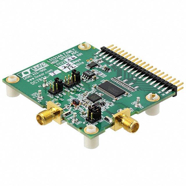
ICGOO在线商城 > 开发板,套件,编程器 > 评估板 - 模数转换器(ADC) > EVAL-AD7686SDZ

 Datasheet下载
- 型号: EVAL-AD7686SDZ
- 制造商: Analog
- 库位|库存: xxxx|xxxx
- 要求:
| 数量阶梯 | 香港交货 | 国内含税 |
| +xxxx | $xxxx | ¥xxxx |
查看当月历史价格
查看今年历史价格
EVAL-AD7686SDZ产品简介:
ICGOO电子元器件商城为您提供EVAL-AD7686SDZ由Analog设计生产,在icgoo商城现货销售,并且可以通过原厂、代理商等渠道进行代购。 EVAL-AD7686SDZ价格参考。AnalogEVAL-AD7686SDZ封装/规格:评估板 - 模数转换器(ADC), AD7686 PulSAR® 16 Bit 500k Samples per Second Analog to Digital Converter (ADC) Evaluation Board。您可以下载EVAL-AD7686SDZ参考资料、Datasheet数据手册功能说明书,资料中有EVAL-AD7686SDZ 详细功能的应用电路图电压和使用方法及教程。
EVAL-AD7686SDZ是Analog Devices Inc.推出的一款评估板,专为测试和开发AD7686模数转换器(ADC)而设计。该评估板主要应用于工业自动化、仪器仪表、医疗设备、通信系统以及数据采集系统等领域。

在工业自动化中,EVAL-AD7686SDZ可用于高精度传感器信号采集与处理,提升控制系统的稳定性与准确性;在精密测量仪器中,如示波器、频谱分析仪等,它可帮助工程师快速验证ADC性能,确保测量精度。

此外,该评估板也适用于研发阶段的原型设计与功能验证,便于开发人员评估AD7686的功耗、分辨率(18位)、采样速率(最高可达250kSPS)及其接口兼容性(SPI接口),从而加快产品开发进程。

综上所述,EVAL-AD7686SDZ广泛适用于需要高精度、中高速模数转换的各种高性能电子系统的设计与评估。
| 参数 | 数值 |
| ADC数 | 1 |
| 产品目录 | 编程器,开发系统 |
| 描述 | BOARD EVAL CTRL AD7686 |
| 产品分类 | 评估板 - 模数转换器 (ADC) |
| 品牌 | Analog Devices Inc |
| 数据手册 | |
| 产品图片 |
|
| 产品型号 | EVAL-AD7686SDZ |
| rohs | 无铅 / 符合限制有害物质指令(RoHS)规范要求 |
| 产品系列 | PulSAR® |
| 不同条件下的功率(典型值) | 15mW @ 500kSPS,5 V |
| 位数 | 16 |
| 使用的IC/零件 | AD7686 |
| 其它名称 | EVALAD7686SDZ |
| 工作温度 | -40°C ~ 85°C |
| 所含物品 | 板,电源 |
| 数据接口 | DSP,MICROWIRE™,QSPI™,串行,SPI™ |
| 标准包装 | 1 |
| 特色产品 | http://www.digikey.cn/product-highlights/cn/zh/analog-devices-solutions-for-xilinx-fpgas/3178 |
| 输入范围 | ±VREF |
| 配用 | /product-detail/zh/SDP-FMC-IB1Z/SDP-FMC-IB1Z-ND/3712519/product-detail/zh/EVAL-SDP-CB1Z/EVAL-SDP-CB1Z-ND/2606896 |
| 采样率(每秒) | 500k |


- 商务部:美国ITC正式对集成电路等产品启动337调查
- 曝三星4nm工艺存在良率问题 高通将骁龙8 Gen1或转产台积电
- 太阳诱电将投资9.5亿元在常州建新厂生产MLCC 预计2023年完工
- 英特尔发布欧洲新工厂建设计划 深化IDM 2.0 战略
- 台积电先进制程称霸业界 有大客户加持明年业绩稳了
- 达到5530亿美元!SIA预计今年全球半导体销售额将创下新高
- 英特尔拟将自动驾驶子公司Mobileye上市 估值或超500亿美元
- 三星加码芯片和SET,合并消费电子和移动部门,撤换高东真等 CEO
- 三星电子宣布重大人事变动 还合并消费电子和移动部门
- 海关总署:前11个月进口集成电路产品价值2.52万亿元 增长14.8%


PDF Datasheet 数据手册内容提取
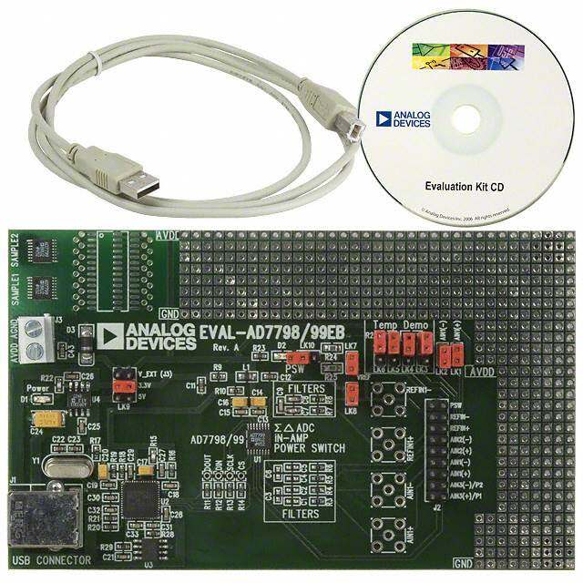
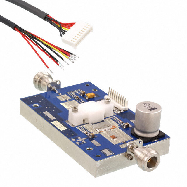
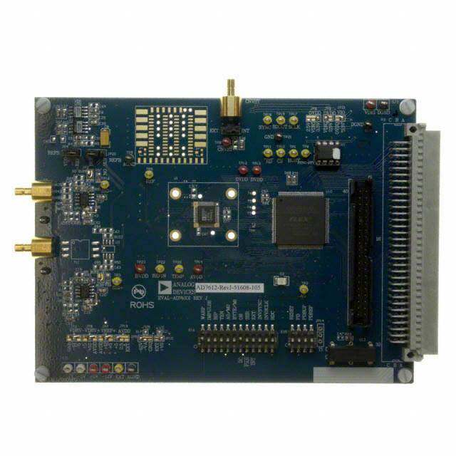
8-/10-Lead PulSAR User Guide UG-340 One Technology Way • P.O. Box 9106 • Norwood, MA 02062-9106, U.S.A. • Tel: 781.329.4700 • Fax: 781.461.3113 • www.analog.com Evaluation Board for the 8-/10-Lead Family of 14-/16-/18-Bit PulSAR ADCs FEATURES The 8-lead PulSAR evaluation board covers the following 8-lead PulSAR ADCs: AD7683 (16-bit), AD7684 (16-bit), and AD7694 Full featured evaluation board for 8-/10-lead PulSAR ADCs (16-bit). Versatile analog signal conditioning circuitry On-board reference, reference buffers, and ADC drivers These low power ADCs offer very high performance of up to PC software for control and data analysis of time and 18 bits with throughputs ranging from 100 kSPS to 1.33 MSPS. frequency domain The evaluation board is designed to demonstrate the performance System demonstration platform compatible (EVAL-SDP-CB1Z) of the ADCs and to provide an easy to understand interface for a variety of system applications. A full description of these EQUIPMENT NEEDED products is available in their respective data sheets, which Evaluation board (see Table 5) should be consulted when using this evaluation board. Wall adapter power supply The evaluation board is ideal for use with Analog Devices, Inc., Additional equipment needed system demonstration platform (SDP). This evaluation board SDP board (EVAL-SDP-CB1Z) (optional) interfaces to the SDP board via a 120-pin connector. SMA Precision source connectors, J6 and J10, are provided for the low noise analog Cable (SMA input to evaluation board) signal source. GENERAL DESCRIPTION On-board components include a high precision buffered band gap The 10-lead PulSAR® evaluation board covers the following 5.0 V reference (ADR435), a signal conditioning circuit with two 10-lead PulSAR analog-to-digital converters (ADCs): AD7685 op amps (ADA4841-1), and a power supply to derive the necessary (16-bit), AD7686 (16-bit), AD7687 (16-bit), AD7688 (16-bit), voltage levels to supply all voltage needs. The 8-lead board also AD7690 (18-bit), AD7691 (18-bit), AD7693 (16-bit), AD7942 includes a level shifter (ADG3304) to interface the ADC with (14-bit), AD7946 (14-bit), AD7980 (16-bit), AD7982 (18-bit), the EVAL-SDP-CB1Z. AD7983 (16-bit), AD7984 (18-bit), AD7988-5 (16-bit), AD7989-5 (18-bit), AD7915 (16-bit) and AD7916 (16-bit). SIMPLIFIED EVALUATION BOARD BLOCK DIAGRAM VIN = 9V WALL ADAPTER (OPTIONAL) –VS POWER SUPPLY CIRCUITRY GND ADP7102, ADP7104, ADP2301 +VS +7.5V/-2.5V 2.5V/5V +7.5V3.3V +5V (OPTIONAL) VDD ADR435 5V 5V GND VCM VSDP AD8031 ADSP-BF527 DSP ADA4841-1 +7.5V VDD REFOVDD VIN+ –2.5V IN+ADC SSCDKI ADA4841-1 +7.5V IN– SDO SPORT GND CNV VIN– A B GLUE LOGIC –2.5V 10-LEAD PulSAR EVALUATION BOARD SDP BOARD 10322-001 Figure 1. PLEASE SEE THE LAST PAGE FOR AN IMPORTANT WARNING AND LEGAL TERMS AND CONDITIONS. Rev. C | Page 1 of 31
UG-340 8-/10-Lead PulSAR User Guide TABLE OF CONTENTS Features .............................................................................................. 1 Running the Software with the Hardware Connected .............7 Equipment Needed ........................................................................... 1 Running the Software Without Hardware .................................8 General Description ......................................................................... 1 Software Operation ...........................................................................9 Simplified Evaluation Board Block Diagram ................................ 1 Description of User Panel ......................................................... 10 Revision History ............................................................................... 2 Waveform Capture ..................................................................... 11 Evaluation Board Kit Contents ....................................................... 3 AC Testing—Histogram ............................................................ 12 Hardware Requirements .................................................................. 3 DC Testing—Histogram ............................................................ 13 Evaluation Board Hardware ............................................................ 4 AC Testing—FFT Capture ........................................................ 13 Setting Up the Evaluation Board ................................................ 4 Summary Tab .............................................................................. 14 Power Supplies .............................................................................. 4 Save File ....................................................................................... 15 Reference ....................................................................................... 4 Load File ...................................................................................... 15 Serial Interface .............................................................................. 4 Evaluation Board Schematics........................................................ 16 Solder Links ................................................................................... 4 Troubleshooting .............................................................................. 29 Analog Inputs ................................................................................ 4 Software ....................................................................................... 29 Evaluation Board Software .............................................................. 5 Hardware ..................................................................................... 29 Installing the Software ................................................................. 5 Products on this Evaluation Board .............................................. 30 Installation Steps ........................................................................... 5 Related Links ............................................................................... 30 Board Operation/Connection Sequence ................................... 7 REVISION HISTORY 3/15—Rev. B to Rev. C 10/12—Rev. 0 to Rev. A Changes to General Description Section ...................................... 1 Added 8-Lead PulSAR Evaluation Board ....................... Universal Changes to Table 3 ............................................................................ 4 Changes to Description of User Panel Section ........................... 10 Changes to Table 5 .......................................................................... 30 Changes to Figure 27 Caption ...................................................... 16 Added Figure 28; Renumbered Sequentially .............................. 17 2/14—Rev. A to Rev. B Changes to Figure 36 Caption and Figure 37 Caption .............. 23 Changes to Equipment Needed Section and General Changes to Figure 38 Caption and Figure 39 Caption .............. 24 Description Section .......................................................................... 1 Changes to Figure 40 Caption ...................................................... 25 Changes to Evaluation Kits Contents Section .............................. 3 Added Figure 41 and Figure 42 .................................................... 26 Change to Table 3 ............................................................................. 4 Added Figure 43 and Figure 44 .................................................... 27 Changes to Table 5 .......................................................................... 30 Added Figure 45 ............................................................................. 28 Changes to Software Section ......................................................... 29 Changes to Table 5 and Related Links Section ........................... 30 5/12—Revision 0: Initial Version Rev. C | Page 2 of 31
8-/10-Lead PulSAR User Guide UG-340 EVALUATION BOARD KIT CONTENTS HARDWARE REQUIREMENTS Evaluation board for ADC of your choice 9 V wall wart (supplied) (U1 device is specific to the evaluation board ordered) Standard USB A to Mini-B USB cable Business card with Analog Devices website address for Signal source, ac source with low distortion, and dc source software and documentation with low noise 9 V wall wart Band-pass filter suitable for 16- and 18-bit testing (value based on signal frequency) SDP board for data transfer to PC Signal source and cables Rev. C | Page 3 of 31
UG-340 8-/10-Lead PulSAR User Guide EVALUATION BOARD HARDWARE SETTING UP THE EVALUATION BOARD Figure 27 shows the evaluation board schematic. The board Table 2. Table of Jumper Detail with Factory Default Setting consists of the ADC, U1, with a reference, U6 (ADR435), and Link Setting Function Comment ADC drivers, U12 and U14 (ADA4841-1). The 8-lead board SL2 A −V Change to B if using bench supplies S also has a level shifter, U16 (ADG3304). SL1 A +V Change to B if using bench supplies S The evaluation board is a flexible design that enables the user to SL3 A V_SDP Change to B if using bench supplies adjust compensation components in addition to operating from SL7 A VDD for Change to B if using bench supplies an adjustable bench top power supply. ADC SL4 A VREF Change to B if using bench supplies POWER SUPPLIES The evaluation board requires power from a wall adapter. The Table 3. Table of Jumpers Specific to Different ADCs on-board power supply design is designed to operate from 9 V. Link Setting Configuration Generic SL10 A Differential AD7684, AD7687, AD7688, Table 1. Power Supplies Provided on the Board input AD7690, AD7691, AD7693, Power Supply (V) Function Components Used AD7982, AD7984, AD7989-5, +5 SDP power ADP2301 AD7915, AD7916 +7.5 Positive rail ADP7102 SL10 B Single-ended AD7683, AD7685, AD7686, −2.5 Negative rail ADP2301 AD7694, AD7942, AD7946, AD7980, AD7983, AD7988-5 +2.5/+5 ADC ADP7104 +3.3 V (digital power) ADP7104 DRIVE ANALOG INPUTS Each supply is decoupled where it enters the board and again at The analog inputs to the evaluation board are SMA connectors, each device. A single ground plane is used on this board to J6 and J10. These inputs are buffered with dedicated amplifier minimize the effect of high frequency noise interference. circuitry (U12 and U14), as shown in Figure 27. The circuit allows In addition to this, there is also the ability to power the board different configurations, input range scaling, filtering, addition of a from a bench top power supply. The screw terminals, J2 and J3, are dc component, and use of different op amp and supplies. The provided for this function. When bench power is used, the wall analog input amplifiers are set as unity-gain buffers at the factory. wart and on-board power supply are no longer required. Solder The amplifier positive rail is driven from 7.5 V (from U13, links also must be changed: SL1 = B, SL2 = B, SL7 = B, SL4 = B, ADP7102). The negative amplifier rail is driven from –VS and SL3 = B. (generated by U3, ADP2301). REFERENCE The default configuration sets both U12 and U14 at midscale, generated from a buffered reference voltage divider (VCM). An external 5 V reference (U6, ADR435) is used to supply the ADCs directly. The evaluation board is factory configured for providing either a single-ended path or a fully differential path as shown in Table 3. SERIAL INTERFACE For dynamic performance, a fast Fourier transform (FFT) test The evaluation board uses the SPORT interface from the ADSP- can be done by applying a very low distortion ac source. BF527 DSP. For low frequency testing, the audio precision source can be used A number of AND gates are used to clock and gate the SPORT directly because the outputs on these are isolated. Set the outputs transfer to the ADC device. See U9, U10, and U11. The 8-lead for balanced and floating ground. Different sources can be used; board also has a level shifter, U16 (ADG3304), which interfaces however, most are single-ended sources that use a fixed output the ADC logic levels (5 V) to the EVAL-SDP-CB1Z (3.3 V). resistance. SOLDER LINKS Because the evaluation board uses the amplifiers in unity-gain, There is one three solder link option on the board. It is configured the noninverting input has a common-mode input with a series depending on which generic of the ADC is on the specific 590 Ω resistor, and it needs to be taken into account when directly evaluation board as described in Table 3. connecting a source (voltage divider). Rev. C | Page 4 of 31
8-/10-Lead PulSAR User Guide UG-340 EVALUATION BOARD SOFTWARE INSTALLING THE SOFTWARE The evaluation board software can be downloaded from the relevant product page on the Analog Devices website. Install the software prior to connecting the SDP board to the USB port of the PC. This ensures that the SDP board is recognized when it connects to the PC. 1. Start the Windows® operating system and download the software from the relevant product page on the Analog Devices website. 2. Unzip the downloaded file. Run the setup.exe file. 3. After installation is completed, power up the evaluation 4. bPoluagr dth aes edveaslcuraibtieodn ibno tahred P inowtoe trh Seu SpDplPie bs osaercdti oannd. the SDP 10322-003 Figure 3. Choose Folder Location, Default Folder Shown board into the PC using a USB cable. 5. When the software detects the evaluation board, proceed through any dialog boxes that appear to finalize the installation. The default location for the software is the following: C:\Program Files\Analog Devices\8 & 10 Lead PulSAR ADCs. This location contains the executable software and example files. INSTALLATION STEPS Proceed through the installation, allowing the software and drivers to be placed in the appropriate locations. Connect the SDP board to the PC only after the software and drivers have been installed. There are two parts to the software installation. First, install the 10322-004 software related to the evaluation board, as shown in Figure 2 to Figure 4. Accept National Instruments Software License Agreement Figure 7. 10322-002 Figure 5. Click Next >> to Install Software 10322-005 Figure 2. Evaluation Board Software Installation Launches Rev. C | Page 5 of 31
UG-340 8-/10-Lead PulSAR User Guide 10322-006 10322-009 Figure 6. Bar Showing Installation Progress Figure 9. Click Next > to Install the ADI SDP Drivers 10322-007 10322-010 Figure 7. Installation Complete, Click Next >> to Complete and Finish Figure 10. Choose Install Location, Default Folder Shown The second part of the software installation is the drivers related to the SDP board. These drivers must be installed for the evaluation board to function correctly. See Figure 8 to Figure 12. 10322-008 Figure 8. Installation for SDP Starting 10322-011 Figure 11. Installation in Progress Rev. C | Page 6 of 31
8-/10-Lead PulSAR User Guide UG-340 RUNNING THE SOFTWARE WITH THE HARDWARE CONNECTED To run the program, take the following steps: 1. Click Start > All Programs > Analog Devices > 8 & 10 Lead PulSAR ADCs. To uninstall the program, click Start > Control Panel > Add or Remove Programs > Analog Devices 8 & 10 Lead PulSAR ADCs. 2. If the SDP board is not connected to the USB port when the software is launched, a connectivity error displays (see Figure 14). Connect the evaluation board to the USB port of the PC, wait a few seconds, click Rescan, and follow the 10322-013 instructions. Figure 12. Click Finish to Complete Installation When you first plug in the SDP board via the USB cable provided, allow the new Found Hardware Wizard to run. You can check that the drivers and the board are connected correctly by looking at the Device Manager of the PC. The Analog Devices System Development Platform (32MB) should appear under ADI Development Tools. 10322-015 Figure 14. SDP Board Not Connected to the USB Port Pop-Up Window Error 3. When evaluation board is detected, Figure 15 displays. Click OK to continue. 10322-014 Figure 13. Device Manager BOARD OPERATION/CONNECTION SEQUENCE The following is the board operation/connection sequence: 1. Connect the SDP controller board to the evaluation board 10322-016 with the J5 connector (screw into place as required). The Figure 15. Software Detects Evaluation Board software is configured to find the evaluation board on either 4. The software then connects to the board and displays what connector of the SDP board. is shown in Figure 16. 2. Power the board with the appropriate supply as described in the Power Supplies section. 3. Connect to the PC with the USB cable. 4. Launch the software. Click Start > All Programs > Analog Devices > 8 & 10 Lead PulSAR ADCs. 5. Apply signal source and capture data. 10322-017 Figure 16. Software Connects to SDP Board 5. When the board is correctly detected, the software panel opens. Rev. C | Page 7 of 31
UG-340 8-/10-Lead PulSAR User Guide RUNNING THE SOFTWARE WITHOUT HARDWARE 3. The software alerts you that no hardware is connected, and that the software will continue in standalone mode. The software can run in standalone mode when no evaluation board hardware is connected to the USB port. 1. Click Start > All Programs > Analog Devices > 8 & 10 Lead PulSAR ADCs. 2. The software automatically seeks to find the hardware connected; therefore, when no hardware is connected, it dwiistphloauyts ha acrodnwnaercet iivni tsyt aenrdroarlo (nseee m Foigduer,e c 1li7ck). CToa nccoenlt. inue 10322-019 Figure 18. Software Indicates Operating in Standalone Mode 4. Within standalone/offline mode, you can load example files or previously saved files and analyze these files. 5. If you decide to connect hardware at this point, close the software and relaunch it to allow the software to search for the board again. 10322-018 Figure 17. No Hardware Connected Pop-Up Window Error Rev. C | Page 8 of 31
8-/10-Lead PulSAR User Guide UG-340 SOFTWARE OPERATION When the software launches, the panel opens and the software looks for the hardware connected to the PC. The software detects the generic attached to the PC (see Figure 19). The product panel then launches. 10322-020 Figure 19. Software Detects AD7691 2 1 10 6 7 8 9 3 4 5 10322-021 Figure 20. Setup Screen Rev. C | Page 9 of 31
UG-340 8-/10-Lead PulSAR User Guide DESCRIPTION OF USER PANEL The following is the description of the user panel: 1. File menu with choice of a. Load Data: load previously captured data b. Sseapvaer Dataedta v aasl u.tessv): fsoarvme acta fpotru rfuedtu drea taan ianl ytssivs (tab 10322-022 Figure 21. Software Overwritten User Settings to a Sample Rate/SCLK Rate c. Save Picture: use to save the current screen capture Suitable for SDP Data Transfer d. Print e. Exit 5. External Reference Voltage. By default, this reference is 5 V (ADR435 on-board reference). The minimum/maximum 2. When hardware is connected to the USB port, the software voltage calculations are based on this reference voltage. If automatically detects which generic is connected and displays the user changes the reference voltage, this input must be it here. Without hardware, the software can be operated in changed accordingly. standalone mode for data analysis, and the device information 6. Click Read to perform a single capture. notes the device number pulled from the saved data file. 3. Sampling Frequency: The default sampling frequency 7. Click Start Stream to perform a continuous capture from the ADC. matches the maximum sample rate of the ADC connected 8. Click Stop Stream to stop streaming data. to the board. The user can adjust the sampling frequency; 9. Select the number of samples (Num Samples) to analyze. however, there are limitations around the sample frequency 10. There are four tabs available that display the data in related to the SCLK frequency applied. The sample frequency different formats: must be an integer divider of the SCLK frequency. In addition, a. Waveform where unusable sample frequencies are input, the software b. Histogram automatically adjusts the sample frequency accordingly. c. FFT Units can be entered, such as 10k for 10,000 Hz. Because d. Summary the maximum sample frequency possible is device dependent, with some of the ADCs capable of operating up to 250 kSPS, To exit the software, go to File > Exit or use the EXIT button in while others can go to 1.3 MSPS, the software matches the the bottom left corner. particular ADC ability. If the user enters a value larger than Within any of the chart panels, the tools shown in Table 4 allow the ability of the existing device, the software indicates this user control of the different chart displays. and reverts to the maximum sample frequency. 4. sCLK Frequency: The default SCLK frequency is set to Table 4. 60 MHz, which is the maximum allowable from the SDP. Symbol Description The SCLK is applied to the ADC SCK pin. The SDP board This tool is used to control the cursor, if present. limits the SCLK frequency; nominal values for correct This tool is used to zoom in and out. operation are 60 MHz, 30 MHz, and 20 MHz. Where the user adjusts the SCLK/sample rate to values that are not This tool is used for panning. supported by the SDP clock or the ADC sample rate, the software overrides by adjusting values accordingly and To save the plot, click Save Plot. identify this to the user (see Figure 21). The SCLK frequency is rounded down. Rev. C | Page 10 of 31
8-/10-Lead PulSAR User Guide UG-340 WAVEFORM CAPTURE Figure 22 illustrates the waveform capture. The input signal is a 1 kHz sine wave. The waveform analysis reports the amplitudes recorded from the captured signal in addition to the frequency of the signal tone. 1 10322-023 Figure 22. Waveform Tab Rev. C | Page 11 of 31
UG-340 8-/10-Lead PulSAR User Guide AC TESTING—HISTOGRAM Note that an ac histogram needs a quality signal source applied to the input J6/J10 connectors. Figure 23 shows the histogram The ac testing histogram tests the ADC for the code distribution for a 1 kHz sine wave applied to the ADC input. for the ac input, computes the mean and standard deviation, or transition noise, of the converter, and displays the results. Raw data Figure 23 shows the histogram results for the signal applied. It is captured and passed to the PC for statistical computations. To also illustrates the different measured values for the data captured perform a histogram test, select Histogram and click Start Stream. (see Number 1 within Figure 23). 1 10322-024 Figure 23. Histogram Tab, Histogram Captured for Sine Wave Rev. C | Page 12 of 31
8-/10-Lead PulSAR User Guide UG-340 DC TESTING—HISTOGRAM and spurious-free dynamic range (SFDR). The data can also be displayed in the time domain. To perform an ac test, apply More commonly, the histogram is used for dc testing where the a sinusoidal signal to the evaluation board at the SMA inputs, user tests the ADC for the code distribution for dc input, computes J6/J10. Low distortion, better than 100 dB, is required to allow the mean and standard deviation, or transition noise, of the true evaluation of the device. One possibility is to filter the input converter, and displays the results. Raw data is captured and signal from the ac source. A band-pass filter can be used, and passed to the PC for statistical computations. To perform a its center frequency must match the test frequency of interest. histogram test, select Histogram and click Start Stream. Note Furthermore, if using a low frequency band-pass filter when that a histogram test can be performed without an external the full-scale input range is more than a few V p-p, use the on- source because the evaluation board has a buffered V /2 REF board amplifiers to amplify the signal, thus preventing the filter source at the ADC input. To test other dc values, apply a source from distorting the input signal. to the J6/J10 inputs. It may be required to filter the signal to make the dc source noise compatible with that of the ADC. Figure 24 displays the histogram of the captured data that includes the following: AC TESTING—FFT CAPTURE The spectrum information This tests the traditional ac characteristics of the converter and displays an FFT of the result. As in the histogram test, raw data The fundamental frequency and amplitude in addition to the second-to-fifth harmonics is captured and passed to the PC where the FFT is performed displaying signal-to-noise ratio (SNR), signal-to-noise-and- The performance data (SNR, dynamic range, THD, distortion ratio (SINAD), total harmonic distortion (THD), SINAD, and noise performance) 2 3 1 10322-025 Figure 24. FFT Tab Rev. C | Page 13 of 31
UG-340 8-/10-Lead PulSAR User Guide SUMMARY TAB The Summary tab captures all the display information and provides them in one panel with a synopsis of the information including key performance parameters, such as SNR and THD. 10322-026 Figure 25. Summary Tab, Shows All Captured Windows Rev. C | Page 14 of 31
8-/10-Lead PulSAR User Guide UG-340 SAVE FILE LOAD FILE The software can save the current captured data for later analysis, The user is prompted with a Load File box. The user may have to and the file format is .tsv (tab separated values). navigate to find these example files. The default location for the example files is C:\Program Files\Analog Devices\8 & 10 Lead The user is prompted with a Choose or Enter Path of File box PulSAR ADCs\Example files. (see Figure 26); save to an appropriate folder location. 10322-027 Figure 26. Save Dialog Box Rev. C | Page 15 of 31
UG-340 8-/10-Lead PulSAR User Guide EVALUATION BOARD SCHEMATICS 821-22301 Figure 27. 10-Lead Evaluation Board, ADC and Driver Rev. C | Page 16 of 31
8-/10-Lead PulSAR User Guide UG-340 822-22301 Figure 28. 8-Lead Evaluation Board, ADC and Driver Rev. C | Page 17 of 31
UG-340 8-/10-Lead PulSAR User Guide 10322-129 Figure 29. Voltage Reference and Common-Mode Buffer 10322-130 Figure 30. Secondary Power Connector for Bench Supply Purposes Rev. C | Page 18 of 31
8-/10-Lead PulSAR User Guide UG-340 131-22301 Figure 31. On-Board Amplifier Power Supply, +7.5/−2.5 V Rev. C | Page 19 of 31
UG-340 8-/10-Lead PulSAR User Guide 10322-132 Figure 32. SDP Power Supply 10322-133 Figure 33. ADC/VDRIVE Power Supply Rev. C | Page 20 of 31
8-/10-Lead PulSAR User Guide UG-340 431-22301 Figure 34. SDP Connector and Glue Logic Rev. C | Page 21 of 31
UG-340 8-/10-Lead PulSAR User Guide 10322-135 Figure 35. Header Connectors, Optional Connectors for Possible Add-On Boards Rev. C | Page 22 of 31
8-/10-Lead PulSAR User Guide UG-340 10322-136 Figure 36. 10-Lead Evaluation Board Silkscreen, Top Layer 10322-137 Figure 37. 10-Lead Evaluation Board, Layer 1 Rev. C | Page 23 of 31
UG-340 8-/10-Lead PulSAR User Guide 10322-138 Figure 38. 10-Lead Evaluation Board, Layer 2 10322-139 Figure 39. 10-Lead Evaluation Board, Layer 3 Rev. C | Page 24 of 31
8-/10-Lead PulSAR User Guide UG-340 10322-140 Figure 40. 10-Lead Evaluation Board, Layer 4 Rev. C | Page 25 of 31
UG-340 8-/10-Lead PulSAR User Guide 10322-141 Figure 41. 8-Lead Evaluation Board Silkscreen, Top Layer 10322-142 Figure 42. 8-Lead Evaluation Board, Layer 1 Rev. C | Page 26 of 31
8-/10-Lead PulSAR User Guide UG-340 10322-143 Figure 43. 8-Lead Evaluation Board, Layer 2 10322-144 Figure 44. 8-Lead Evaluation Board, Layer 3 Rev. C | Page 27 of 31
UG-340 8-/10-Lead PulSAR User Guide 10322-145 Figure 45. 8-Lead Evaluation Board, Layer 4 Rev. C | Page 28 of 31
8-/10-Lead PulSAR User Guide UG-340 TROUBLESHOOTING SOFTWARE HARDWARE To troubleshoot the software, take the following steps: To troubleshoot the hardware, take the following steps: 1. Always install the software prior to connecting the hardware 1. If the software does not read any data back, do the to the PC. following: 2. Always allow the install to fully complete (the software is a a. Check that the power is applied within the power 2-part install, the ADC software and the SDP drivers). This ranges described in the Power Supplies section. may require a restart. b. Using a voltmeter, measure the voltage present at the 3. When the user first plugs in the SDP board via the USB cable positive terminal of C3 (it should be 7.5 V) and C14 provided, allow the new Found Hardware Wizard to run. (it should be −2.5 V) and measure the voltage at the This may take a little time but allow this to happen prior to positive terminal of C11 (it should be 5 V). The SDP starting the software. board, LED1, should be lit. 4. Where the board does not appear to be functioning, ensure c. Launch the software and read the data. If nothing that the ADC evaluation board is connected to the SDP board happens, exit the software. and that the board is being recognized in the Device d. Power down the board and relaunch the software. Manager, as shown in Figure 13. e. If no data is read back, confirm that the ADC evaluation 5. If connected to a slower USB port where the SDP cannot read board is connected to the SDP board and that the board as quickly as it needs to, a timeout error may result. In this is being recognized in the Device Manager, as shown case, it is advised not to read continuously, or alternatively, in Figure 13. to lower the number of samples taken. 2. When the user is working with the software in standalone/ offline mode (no hardware connected) and later chooses to connect hardware, they must close and relaunch the software. Rev. C | Page 29 of 31
UG-340 8-/10-Lead PulSAR User Guide PRODUCTS ON THIS EVALUATION BOARD Table 5. Product Ordering Model Sample Rate Resolution (Bit) Package Used on Evaluation Board AD7683BRMZ EVAL-AD7683SDZ 100 kSPS 16 8-Lead MSOP AD7684BRMZ EVAL-AD7684SDZ 100 kSPS 16 8-Lead MSOP AD7685BRMZ EVAL-AD7685SDZ 250 kSPS 16 10-Lead MSOP AD7686BRMZ EVAL-AD7686SDZ 500 kSPS 16 10-Lead MSOP AD7687BRMZ EVAL-AD7687SDZ 250 kSPS 16 10-Lead MSOP AD7688BRMZ EVAL-AD7688SDZ 500 kSPS 16 10-Lead MSOP AD7690BRMZ EVAL-AD7690SDZ 400 kSPS 18 10-Lead MSOP AD7691BRMZ EVAL-AD7691SDZ 250 kSPS 18 10-Lead MSOP AD7693BRMZ EVAL-AD7693SDZ 500 kSPS 16 10-Lead MSOP AD7694BRMZ EVAL-AD7694SDZ 250 kSPS 16 8-Lead MSOP AD7942BRMZ EVAL-AD7942SDZ 250 kSPS 14 10-Lead MSOP AD7946BRMZ EVAL-AD7946SDZ 500 kSPS 14 10-Lead MSOP AD7980BRMZ EVAL-AD7980SDZ 1 MSPS 16 10-Lead MSOP AD7982BRMZ EVAL-AD7982SDZ 1 MSPS 18 10-Lead MSOP AD7983BRMZ EVAL-AD7983SDZ 1.33 MSPS 16 10-Lead MSOP AD7984BRMZ EVAL-AD7984SDZ 1.33 MSPS 18 10-Lead MSOP AD7988-5BRMZ EVAL-AD7988-5SDZ 500 kSPS 16 10-Lead MSOP AD7915BRMZ EVAL-AD7915SDZ 1 MSPS 16 10-Lead MSOP AD7916BRMZ EVAL-AD7916SDZ 500 kSPS 16 10-Lead MSOP RELATED LINKS Resource Description AD8031 Product Page, AD8031, 2.7 V, 800 µA, 80 MHz Rail-to-Rail I/O Single Amplifier ADA4841-1 Product Page, ADA4841-1, Low Power, Low Noise and Distortion, Rail-to-Rail Output Amplifier ADR435 Product Page, ADR435, Ultralow Noise XFET® Voltage References with Current Sink and Source Capability ADP7102 Product Page, ADP7102, 20 V, 300 mA, Low Noise, CMOS LDO ADP7104 Product Page, ADP7104, 20 V, 500 mA, Low Noise, CMOS LDO ADP2301 Product Page, ADP2301, 1.2 A, 20 V, 1.4 MHz Nonsynchronous Step-Down Switching Regulator ADG3304 Product Page, ADG3304, Low Voltage 1.15 V to 5.5 V, 4 Channel, Bidirectional, Logic Level Translator EVAL-SDP-CB1Z Product Page, System Demonstration Platform (SDP) AN-931 AN-931 Application Note, Understanding PulSAR ADC Support Circuitry Rev. C | Page 30 of 31
8-/10-Lead PulSAR User Guide UG-340 NOTES ESD Caution ESD (electrostatic discharge) sensitive device. Charged devices and circuit boards can discharge without detection. Although this product features patented or proprietary protection circuitry, damage may occur on devices subjected to high energy ESD. Therefore, proper ESD precautions should be taken to avoid performance degradation or loss of functionality. Legal Terms and Conditions By using the evaluation board discussed herein (together with any tools, components documentation or support materials, the “Evaluation Board”), you are agreeing to be bound by the terms and conditions set forth below (“Agreement”) unless you have purchased the Evaluation Board, in which case the Analog Devices Standard Terms and Conditions of Sale shall govern. Do not use the Evaluation Board until you have read and agreed to the Agreement. Your use of the Evaluation Board shall signify your acceptance of the Agreement. This Agreement is made by and between you (“Customer”) and Analog Devices, Inc. (“ADI”), with its principal place of business at One Technology Way, Norwood, MA 02062, USA. Subject to the terms and conditions of the Agreement, ADI hereby grants to Customer a free, limited, personal, temporary, non-exclusive, non-sublicensable, non-transferable license to use the Evaluation Board FOR EVALUATION PURPOSES ONLY. Customer understands and agrees that the Evaluation Board is provided for the sole and exclusive purpose referenced above, and agrees not to use the Evaluation Board for any other purpose. Furthermore, the license granted is expressly made subject to the following additional limitations: Customer shall not (i) rent, lease, display, sell, transfer, assign, sublicense, or distribute the Evaluation Board; and (ii) permit any Third Party to access the Evaluation Board. As used herein, the term “Third Party” includes any entity other than ADI, Customer, their employees, affiliates and in-house consultants. The Evaluation Board is NOT sold to Customer; all rights not expressly granted herein, including ownership of the Evaluation Board, are reserved by ADI. CONFIDENTIALITY. This Agreement and the Evaluation Board shall all be considered the confidential and proprietary information of ADI. Customer may not disclose or transfer any portion of the Evaluation Board to any other party for any reason. Upon discontinuation of use of the Evaluation Board or termination of this Agreement, Customer agrees to promptly return the Evaluation Board to ADI. ADDITIONAL RESTRICTIONS. Customer may not disassemble, decompile or reverse engineer chips on the Evaluation Board. Customer shall inform ADI of any occurred damages or any modifications or alterations it makes to the Evaluation Board, including but not limited to soldering or any other activity that affects the material content of the Evaluation Board. Modifications to the Evaluation Board must comply with applicable law, including but not limited to the RoHS Directive. TERMINATION. ADI may terminate this Agreement at any time upon giving written notice to Customer. Customer agrees to return to ADI the Evaluation Board at that time. LIMITATION OF LIABILITY. THE EVALUATION BOARD PROVIDED HEREUNDER IS PROVIDED “AS IS” AND ADI MAKES NO WARRANTIES OR REPRESENTATIONS OF ANY KIND WITH RESPECT TO IT. ADI SPECIFICALLY DISCLAIMS ANY REPRESENTATIONS, ENDORSEMENTS, GUARANTEES, OR WARRANTIES, EXPRESS OR IMPLIED, RELATED TO THE EVALUATION BOARD INCLUDING, BUT NOT LIMITED TO, THE IMPLIED WARRANTY OF MERCHANTABILITY, TITLE, FITNESS FOR A PARTICULAR PURPOSE OR NONINFRINGEMENT OF INTELLECTUAL PROPERTY RIGHTS. IN NO EVENT WILL ADI AND ITS LICENSORS BE LIABLE FOR ANY INCIDENTAL, SPECIAL, INDIRECT, OR CONSEQUENTIAL DAMAGES RESULTING FROM CUSTOMER’S POSSESSION OR USE OF THE EVALUATION BOARD, INCLUDING BUT NOT LIMITED TO LOST PROFITS, DELAY COSTS, LABOR COSTS OR LOSS OF GOODWILL. ADI’S TOTAL LIABILITY FROM ANY AND ALL CAUSES SHALL BE LIMITED TO THE AMOUNT OF ONE HUNDRED US DOLLARS ($100.00). EXPORT. Customer agrees that it will not directly or indirectly export the Evaluation Board to another country, and that it will comply with all applicable United States federal laws and regulations relating to exports. GOVERNING LAW. This Agreement shall be governed by and construed in accordance with the substantive laws of the Commonwealth of Massachusetts (excluding conflict of law rules). Any legal action regarding this Agreement will be heard in the state or federal courts having jurisdiction in Suffolk County, Massachusetts, and Customer hereby submits to the personal jurisdiction and venue of such courts. The United Nations Convention on Contracts for the International Sale of Goods shall not apply to this Agreement and is expressly disclaimed. ©2012–2015 Analog Devices, Inc. All rights reserved. Trademarks and registered trademarks are the property of their respective owners. UG10322-0-3/15(C) Rev. C | Page 31 of 31