
 Datasheet下载
- 型号: EMS22P50-B28-LS6
- 制造商: Bourns
- 库位|库存: xxxx|xxxx
- 要求:
| 数量阶梯 | 香港交货 | 国内含税 |
| +xxxx | $xxxx | ¥xxxx |
查看当月历史价格
查看今年历史价格
EMS22P50-B28-LS6产品简介:
ICGOO电子元器件商城为您提供EMS22P50-B28-LS6由Bourns设计生产,在icgoo商城现货销售,并且可以通过原厂、代理商等渠道进行代购。 EMS22P50-B28-LS6价格参考¥301.78-¥351.19。BournsEMS22P50-B28-LS6封装/规格:编码器, 。您可以下载EMS22P50-B28-LS6参考资料、Datasheet数据手册功能说明书,资料中有EMS22P50-B28-LS6 详细功能的应用电路图电压和使用方法及教程。
Bourns Inc.的EMS22P50-B28-LS6是一款多圈绝对值编码器,主要应用于需要高精度位置检测和可靠反馈的工业自动化和控制系统中。该编码器具备非接触式磁感应技术,具有较高的耐用性和抗污染能力,适合在恶劣工业环境中使用。

其典型应用场景包括:

1. 工业机器人:用于关节或轴的位置反馈,确保精确的运动控制和定位。

2. 伺服电机控制系统:提供精确的转子位置信息,提升电机控制性能。

3. 包装与印刷机械:实现对传送带、滚筒等部件的精准位置控制。

4. 纺织机械:用于纺纱、编织设备中,确保高精度运动控制。

5. 升降设备与起重机:用于监测吊臂或升降平台的位置,提升操作安全性和精度。

6. 测试与测量设备:用于实验室仪器或检测设备中,提供稳定可靠的角度反馈。

该编码器采用紧凑设计,支持多种输出协议(如SSI、BiSS),便于集成到不同控制系统中,适用于需要高可靠性与稳定性的工业场合。
| 参数 | 数值 |
| 产品目录 | |
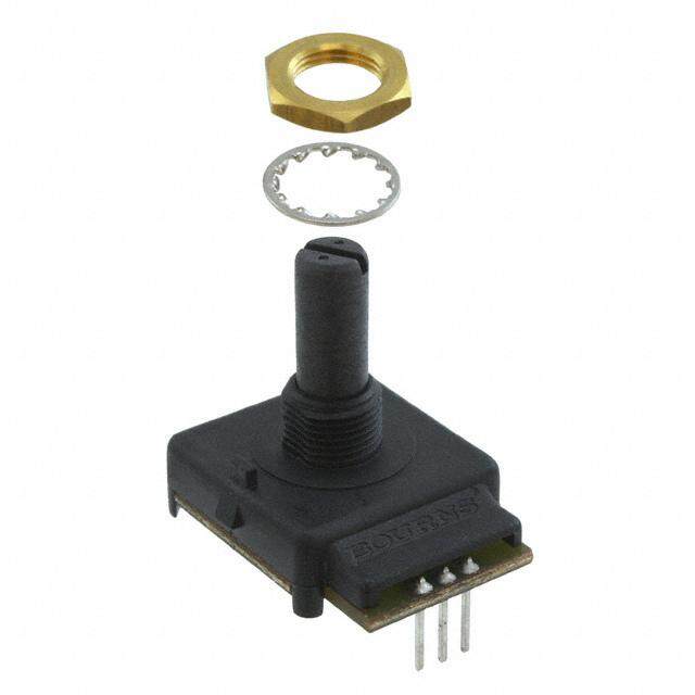
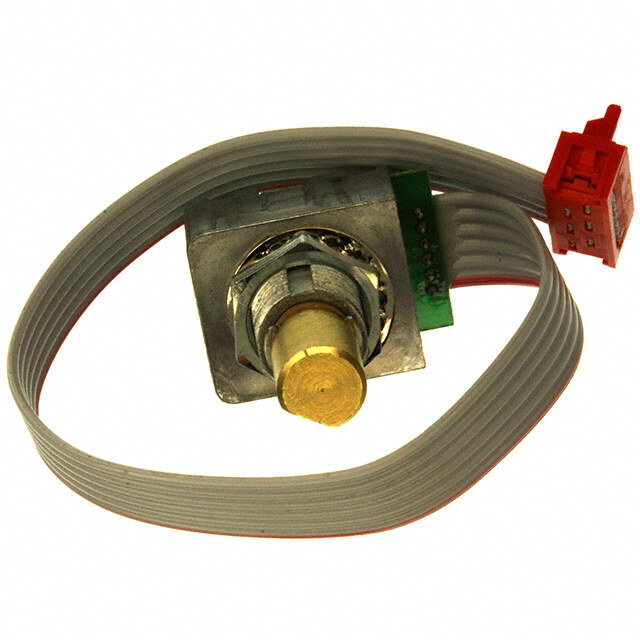
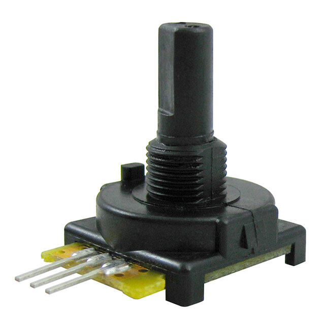
| 描述 | IC ENCODER ABS MAGNETIC编码器 PWM Encoder |
| 产品分类 | |
| 品牌 | Bourns |
| 产品手册 | |
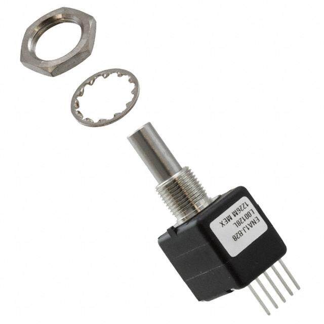
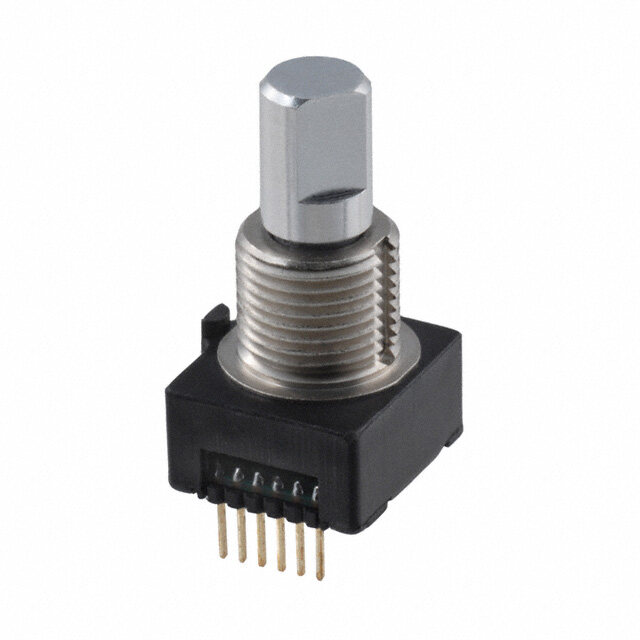
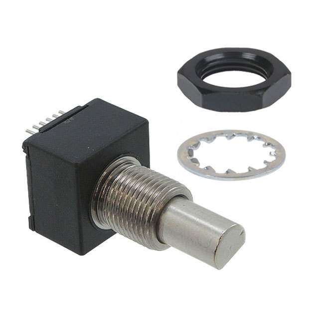
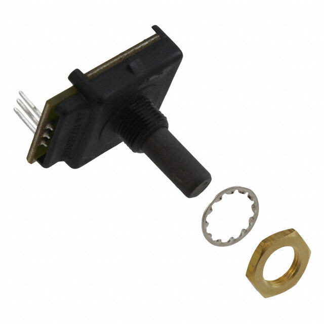
| 产品图片 |
|
| rohs | 符合RoHS无铅 / 符合限制有害物质指令(RoHS)规范要求 |
| 产品系列 | Bourns EMS22P50-B28-LS6- |
| mouser_ship_limit | 该产品可能需要其他文件才能进口到中国。 |
| 数据手册 | |
| 产品型号 | EMS22P50-B28-LS6 |
| RoHS指令信息 | |
| 产品 | Magnetic Encoders |
| 产品培训模块 | http://www.digikey.cn/PTM/IndividualPTM.page?site=cn&lang=zhs&ptm=26280 |
| 产品种类 | |
| 内置开关 | - |
| 分辨率 | 1024 States |
| 制动器数量 | No Detent |
| 单位重量 | 11 g |
| 商标 | Bourns |
| 大小/尺寸 | 21 mm x 16 mm |
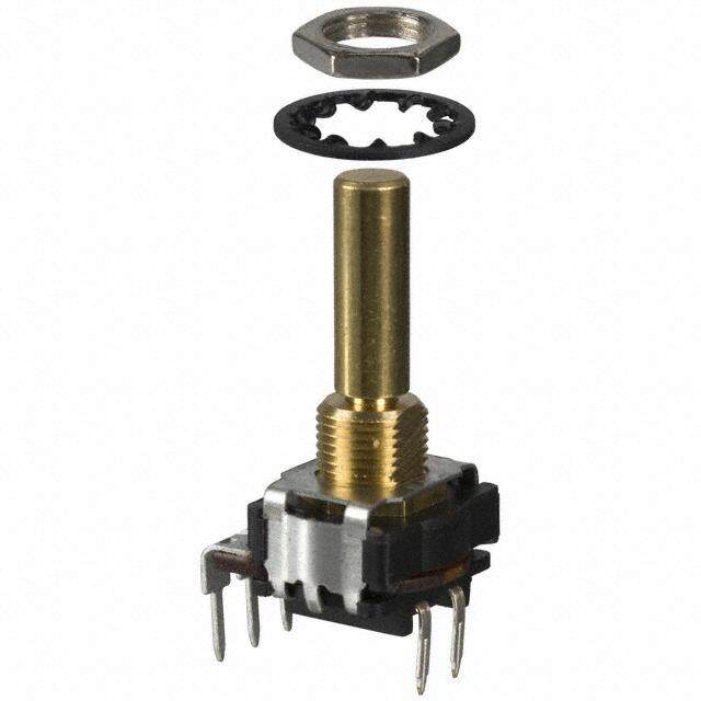
| 套管材料 | Metal |
| 套管螺纹 | 3/8-32 UNEF-2A |
| 安装类型 | 面板安装 |
| 安装风格 | Panel |
| 工作温度范围 | - 40 C to + 125 C |
| 工厂包装数量 | 42 |
| 带开关 | No Switch |
| 技术 | Rotary |
| 旋转寿命(最少次数) | 100M |
| 朝向 | 垂直 |
| 标准包装 | 42 |
| 棘爪 | 无 |
| 每转脉冲数 | 1024 |
| 电压-电源 | 5V |
| 电源电压 | 5 V |
| 端子类型 | PC 引脚 |
| 端接类型 | Through Hole |
| 类型 | Incremental |
| 系列 | EMS22P |
| 编码器类型 | 磁性 |
| 致动器类型 | 1/4" 直径圆形端头 |
| 衬套大小 | 3/8 in x 3/8 in |
| 轴直径 | 1/4 in |
| 轴类型 | Round / Plain |
| 轴长度 | 7/8 in |
| 输出 | Pulse Width Modulated |
| 输出类型 | PWM |
| 通道数量 | 1 Channel |


- 商务部:美国ITC正式对集成电路等产品启动337调查
- 曝三星4nm工艺存在良率问题 高通将骁龙8 Gen1或转产台积电
- 太阳诱电将投资9.5亿元在常州建新厂生产MLCC 预计2023年完工
- 英特尔发布欧洲新工厂建设计划 深化IDM 2.0 战略
- 台积电先进制程称霸业界 有大客户加持明年业绩稳了
- 达到5530亿美元!SIA预计今年全球半导体销售额将创下新高
- 英特尔拟将自动驾驶子公司Mobileye上市 估值或超500亿美元
- 三星加码芯片和SET,合并消费电子和移动部门,撤换高东真等 CEO
- 三星电子宣布重大人事变动 还合并消费电子和移动部门
- 海关总署:前11个月进口集成电路产品价值2.52万亿元 增长14.8%


PDF Datasheet 数据手册内容提取
Features n Resolution: 1024 states n 3.3 and 5 VDC voltage supply option n Long life n PWM Absolute Position n High operating speed n Bushing or servo mount n Highly repeatable n Non-contacting magnetic technology n Sealed option n Small size n Magnetic technology n CMOS and TTL compatible EMS22P - Non-Contacting PWM Encoder Electrical Characteristics Resolution ................................................................................................................................................................................................................1024 states Insulation Resistance (500 VDC) ......................................................................................................................................................................1,000 megohms Electrical Travel ........................................................................................................................................................................................................Continuous Supply Voltage ........................................................................................................................................................................5.0 VDC ±10 %, 3.3 VDC ±10 % Supply Current .................................................................................................................................................................................................20 mA maximum Output Voltage Low Output Level .................................................................................................................................................................................Vss+0.4 V maximum High Output Level...................................................................................................................................................................................Vdd-0.5 V minimum Output Current With 4.5 VDC Supply Voltage .......................................................................................................................................................................4 mA maximum With 3.0 VDC Supply Voltage .......................................................................................................................................................................2 mA maximum Rise/Fall Time (Incremental Output) ...............................................................................................................................................................500 ns maximum Shaft RPM (Ball Bearing) .........................................................................................................................................................................10,000 rpm maximum Linearity ..............................................................................................................................................................................................................................0.5 % Accuracy Nominal ..........................................................................................................................................................................................................±0.7 ° or better Worst Case ...................................................................................................................................................................................................................±1.4 ° Output Transition Noise ...................................................................................................................................................................................0.12 ° RMS max. Environmental Characteristics Operating Temperature Range ........................................................................................................................................-40 ºC to +125 ºC (-40 °F to +257 °F) Storage Temperature Range ...........................................................................................................................................-55 °C to +125 °C (-67 °F to +257 °F) Humidity ....................................................................................................................................................................MIL-STD-202, Method 103B, Condition B Vibration ..............................................................................................................................................................................................................................15 G Shock ..................................................................................................................................................................................................................................50 G Rotational Life S Bushing (@1,000 rpm) .................................................................................................................................................................100,000,000 revolutions T & W Bushings (@1,000 rpm with 250 g side load) ........................................................................................................................50,000,000 revolutions IP Rating .............................................................................................................................................................................................................................IP 65 Mechanical Characteristics Mechanical Angle ............................................................................................................................................................................................360 ° Continuous Torque Starting ....................................................................................................................................................................................43 ±21 g-cm (0.6 ±0.3 oz-in.) Running ...................................................................................................................................................................................29 ±14 g-cm (0.4 ±0.2 oz-in.) Mounting Torque .........................................................................................................................................................................................203 N-cm (18 lb.-in.) Shaft End Play ......................................................................................................................................................................0.30 mm (0.012 ”) T.I.R. maximum Shaft Radial Play ..................................................................................................................................................................0.12 mm (0.005 ”) T.I.R. maximum Weight ..............................................................................................................................................................................................................11 gms. (0.4 oz.) Terminals .........................................................................................................................................................................................Axial, radial or ribbon cable Soldering Condition Manual Soldering ....................................................................................................................96.5Sn/3.0Ag/0.5Cu solid wire or no-clean rosin cored wire 370 °C (700 °F) max. for 3 seconds Wave Soldering .............................................................................................................................................96.5Sn/3.0Ag/0.5Cu solder with no-clean flux 260 °C (500 °F) max. for 10 seconds Wash processes .......................................................................................................................................................................................Not recommended Marking ....................................................................................................................................Manufacturer’s trademark, name, part number, and date code. Hardware ....................................................................One lockwasher and one mounting nut supplied with each encoder, except on servo mount versions. Pin Configuration Output Type Pin 1 Pin 2 Pin 3 Pin 4 Pin 5 Pin 6 PWM PWM Signal GND GND GND VCC* CS** * Can be 5 or 3.3 VDC depending on the version. ** Active low chip select pin; if not used connect pin 6 to GND. WARNING Cancer and Reproductive Harm - www.P65Warnings.ca.gov *RoHS Directive 2015/863, Mar 31, 2015 and Annex. Specifications are subject to change without notice. Users should verify actual device performance in their specific applications. The products described herein and this document are subject to specific legal disclaimers as set forth on the last page o f this document, and at www.bourns.com/docs/legal/disclaimer.pdf.
QQuuaaddrraattuurree OOuuttppuutt 336600 °°== 11 CCyyccllee PPPPRR 33..33 VVcccc 55..00 VVcccc IInnddeexx 11 IInnddeexx 33 PPPPRR 225566 XX XX EEddggee SSeeppaarraattiioonn 225566 XX XX 225566 XX XX 225566 XX XX 112288 XX XX AA 112288 XX XX 112288 XX XX 112288 XX XX 6644 XX XX BB 6644 XX XX IInnddeexx 11 == 11 LLSSBB 6644 XX XX 6644 XX XX 3322 XX XX ZZ 3322 XX XX 3322 XX XX IInnddeexx 33 == 33 LLSSBB 3322 XX XX AAbbssoolluuttee OOuuttppuutt CCSSnn tt CCSSnn tt CCLLKKFFEE TT CCLLKK//22 Applications 00 n Medical (lo77w/medium risk)* 1155 00 n Material handling equipment CCLLKK n Office equipment n Brushless DC motor commutation n Audio and broadcast equipment n Robotics n Automotive n Industrial automatioDDn00 DD99 DD88 DD77 DD66 DD55 DD44 DD33 DD22 DD11 DD00 SS11 SS22 SS33 SS44 SS55 PP11 DD99 n Petroleum refinery EMS22P - Non-Contacting PWM Encoder tt DD00 TTrriissttaattee tt DD00 aaccttiivvee tt DD00 vvaalliidd AAnngguullaarr PPoossiittiioonn DDaattaa SSttaattuuss BBiittss PPaarriittyy BBiitt Output Type Waveform and Variant Table AAnnggllee PPWW MMIINN PPWWMM OOuuttppuutt PPaarraammeetteerr SSyymmbbooll TTyyppee UUnniitt NNoottee 00 ddeegg ((PPooss 00)) PPWWMM ffrreeqquueennccyy ffPPWWMM 00..99775566 KKHHzz SSiiggnnaall ppeerriioodd:: 11002255 μμss MMIINN ppuullssee wwiitthh PPWWMMIINN 11 μμss PPoossiittiioonn 00 AAnnggllee 00 °° MMAAXX ppuullssee wwiitthh PPWWMMAAXX 11002244 μμss PPoossiittiioonn 11002233 AAnnggllee 335599..6655 °° 11 11002255 PPWW MMAAXX AAnnaalloogg oouuttppuutt uussiinngg aann eexxtteerrnnaall llooww ppaassss ffiilltteerr VVcccc tt oonn tt ooffff 00 551122 11002255 335599..6655 ddeegg 00 VV ((PPooss 11002233)) 00 °° 336600 °° RR 11//ff PPWWMM VViinn VVoouutt PPoossiittiioonn == tt oonn ** 11002255//((tt oonn ++ tt ooffff)) -- 11 RecommendedCC Filter R1 R2 analog out DDiirreeccttiioonn//SStteepp OOuuttppuutt PWM PPPPRR 33..33 VVccccC551..00 VVcccc IInnddeexx 11 IInnCdd2eexx 33 551122 XX XX IInnddeexx 11 == 11 LLSSBB 551122 XX XX 551122 XX XX 551122 XX XX ZZ 225566 XX XX VSS 225566 XX XX IInnddeexx 33 == 33 LLSSBB 225566 XX XX Simple Passive 2nd Order Low Pass Filter 225566 XX XX 112288 XX XX LLSSBB R1, R11222 ≥88 4.7KXX Ohms C1, C2XX ≥ 1 μF / 6 V 112288 XX XX R1 should be ≥11 422.887K ohms to aXXvoid loading of tXXhe PWM output. Larger values of66 R44x andXX Cx will provideXX better filtering and less ripple, but will a66ls44o slowXX down the response timXXe. CCWW CCCCWW 6644 XX XX DDiirreeccttiioonn * Bourns® products have not been designed for and are not intended for use in “lifesaving,” “life-critical” or “life-sustaining” applications nor any other applications where failure or malfunction of the Bourns®66 44product may resulXXt in personal injury oXXr death. See Legal Disclaimer Notice www.bourns.com/docs/legal/disclaimer.pdf. tt DDiirr vvaalliidd 550000 nnss Specifications are subject to change without notice. Users should verify actual device performance in their specific applications. The products described herein and this document are subject to specific legal disclaimers as set forth on the last page of this document, and at www.bourns.com/docs/legal/disclaimer.pdf.
Consult factory for options not shown, including: • Wire lead or cable options • Special shaft/bushing sizes and features • Connectors • Special performance characteristics • Non-standard resolutions • PCB mounting bracket EMS22P - Non-Contacting PWM Encoder Product Dimensions Shaft Style D (Bushing T) 13.89 ± .38 15.88 ± .25 (.547 ± .015) 7.94 ± .12 (.625 ± .010) 1.57 ± .12 (.313 ± .005) (.062 ± .005) 10.29 ± .05 (.405 ± .002) 3/8-32 UNEF-2A THD DIA. 3.17 +.00/-.01 DIA. (.1247 +.0000/-.0003) 21.21 ± .25 (.835 ± .010) .51 ± .03 (.020 ± .001) 6 PLCS. AR LUG 9.53 ± .12 1.18 ± .12 (.375 ± .005) R (.047 ± .005) (.21.1709 ±± ..01025) (.0.5210 ±± ..00301) (.41.5070 ±± ..05210 ) L ±(.07381) X(H.00IG.266H6 ±(± F .M.0102S5)) (.73.1935 ±± ..01025) 2.01 ± .12 6 PLCS. (.079 ± .005) DIMENSION L 10.67 ± .12 5 PLCS. (.420 ± .005) 12.7 15.88 22.23 DIA. (.500) (.625) (.875) 3.18 ± .12 (.125 ± .005) DIA. PANEL LAYOUT Shaft Style B (Bushing S) 15.88 ± .25 13.89 ± .38 (.625 ± .010) (.547 ± .015) 7.94 ± .12 1.57 ± .12 (.313 ± .005) (.062 ± .005) DIA. 6.342 ± .008 3/8-32 UNEF-2A THD (0.2497 ± .0003) 21.21 ± .25 10.29 ± .05 (.835 ± .010) (.405 ± .002) DIA. .51 ± .03 (.020 ± .001) 6 PLCS. AR LUG 1.18 ± 0.12 R 9.53 ± .12 (.047 ± .005) (.375 ± .005) X0.66 ± 0.12 (.026 ± .005) 78 2.79 ± .12 (.41.5070 ±± ..05210 ) L ±(.031) HIGH (FMS) (.73.1935 ±± ..01025) (.110 ± .005) (.205.70 9P1 L ±±C ..0S10.25) (.0.52610 P ±±L C..00S30.1) DIMENSION L (1.402.60D7 ±I A± .. 0.1025) 12.7 15.88 22.23 (.500) (.625) (.875) MM 3.18 ± .12 DIMENSIONS: (.125 ± .005) (INCHES) DIA. PANEL LAYOUT 13.89 ± .38 9.53 ± .12 Specifications are subject to change without notice. (.547 ± .015) (.375 ± .005) Users should verify actual devic1e5 p.8e8r ±fo .r2m5ance in their specific applications. 1.57 ± .12 The products described herein a(.n6d2 5t h±i s.0 1d0o)cument are subject to specific legal disclaimers as set forth on the last page of this doc(u.0m62e ±n t.,0 0a5n)d at www.bourns.com/docs/legal/disclaimer.pdf. 3.17 +0/-.01 DIA. (.1247 +0/-.0003) 22.23 ± .12 (.875 ± .005) DIA. 19.81 ± .12 21.21 ± .25 (.780 ± .005) (.835 ± .010) DIA. 19.05 ± .01 (.7500 ± .0005) .51 ± .03 DIA. (.020 ± .001) 6 PLCS. .51 ± .03 1.57 ± .12 (2.1.71904 ± ± . 0.1025) 2.01 ± .12 (.0260 P ±L C.0S0.1) 4.00 ± .51( .062 ± .005) (.10.6527 ±± ..01025) (.079 ± .005) (.157 ± .020) 5 PLCS. L ± 78 (.031)
13.89 ± .38 15.88 ± .25 (.547 ± .015) 7.94 ± .12 (.625 ± .010) 1.57 ± .12 (.313 ± .005) (.062 ± .005) 10.29 ± .05 (.405 ± .002) 3/8-32 UNEF-2A THD DIA. 3.17 +.00/-.01 DIA. (.1247 +.0000/-.0003) 21.21 ± .25 (.835 ± .010) .51 ± .03 (.020 ± .001) 6 PLCS. AR LUG 9.53 ± .12 1.18 ± .12 (.375 ± .005) R (.047 ± .005) (.21.1709 ±± ..01025) (.0.5210 ±± ..00301) (.41.5070 ±± ..05210 ) L ±(.07381) X(H.00IG.266H6 ±(± F .M.0102S5)) (.73.1935 ±± ..01025) 2.01 ± .12 6 PLCS. (.079 ± .005) 10.67 ± .12 5 PLCS. (.420 ± .005) DIA. 3.18 ± .12 (.125 ± .005) DIA. PANEL LAYOUT 15.88 ± .25 13.89 ± .38 (.625 ± .010) (.547 ± .015) 7.94 ± .12 1.57 ± .12 (.313 ± .005) (.062 ± .005) DIA. 6.342 ± .008 3/8-32 UNEF-2A THD (0.2497 ± .0003) 21.21 ± .25 10.29 ± .05 (.835 ± .010) (.405 ± .002) DIA. .51 ± .03 (.020 ± .001) 6 PLCS. AR LUG 1.18 ± 0.12 R 9.53 ± .12 (.047 ± .005) (.375 ± .005) X0.66 ± 0.12 (.026 ± .005) 78 2.79 ± .12 (.41.5070 ±± ..05210 ) L ±(.031) HIGH (FMS) (.73.1935 ±± ..01025) (.110 ± .005) (.205.70 9P1 L ±±C ..0S10.25) (.0.52610 P ±±L C..00S30.1) (1.402.60D7 ±I A± .. 0.1025) EMS22P - Non-Contacting PWM Encoder 3.18 ± .12 (.125 ± .005) DIA. Product Dimensions (Continued) PANEL LAYOUT Shaft Style D (Bushing W) 13.89 ± .38 9.53 ± .12 (.547 ± .015) (.375 ± .005) 15.88 ± .25 1.57 ± .12 (.625 ± .010) (.062 ± .005) 3.17 +0/-.01 DIA. (.1247 +0/-.0003) (1.652.858 ± ± . 0.2150) (1.534.879 ± ± . 0.3185) 1.57 ± .12 10.29 ± .05 (.73.1934 ±± ..01025) .78 (2.827.25D3 ±I A± . 0..1025) L ± (.062 ± .005) (.405 ± .002) (.031) 19.81 ± .12 DIA. 21.21 ± .25 (.780 ± .005) 3/8-32 UNEF-2A THD (.835 ± .010) 3/8-32 UNEF-2A THD DIA. DIA. 3.17 +.00/-.01 19.05 ± .01 (.1247 +.0000/-.0003) (.7500 ± .0005) .51 ± .03 DIA. 21.21 ± .25 (.020 ± .001) (.835 ± .010) 6 PLCS. .51 ± .03 (.020 ± .001) .25 6 PLCS. AR LUG .51 ± .03 1.57 ± .12 F ±(.010) (.93.7553 ±± ..01025) (2.1RX.71((90..4 0010± .2.4± 61.67 068. 10 ± ±±±25 . .).0.011002255)) (.205.70 9P1 L ±±C ..0S10.25) (.0260 P ±L C.0S0.1) (.41.5070 ±± ..05210( .)062 ± .005) L ± (.7108.6527 ±± ..01025) (.2(51.1.558204 .+70 +.0 ).D0000IM//--..(E120.51N560.2S8)5I8O)N L(2.28.7253) 4.00 ± .51 L ± 78 HIGH (FMS) (.031) 2.79 ± .12 .51 ± .03 (.157 ± .020) (.031) (.110 ± .005) (.020 ± .001) 7.95 ± .12 15.88 ± .25 13.89 ± .38 2.01 ± .12 6 PLCS. 7.94 ± .12 Shaft Style C (Bushing S) (.313 ± .005) Shaft Style M (Bushing D) (.625 ± .010) (.547 ± .015) (.10.6527 ±± ..01025) (1.400.259 ±( ± ..0 05.700 9P52 )L±C .0S0.5) (.313 ± .005) (1.402.60L7 ± ±± . 0.(10..02573)81) 24.99 ± .78 DIA. DIA. (.984 ± .031) 3/8-32 UNEF-2A THD 3/8-32 UNEF-2A THD M9 x 0.75 - 6g 3.17 +.00/-.01 DIA. (.1247 +.0000/-.0003) 3.18 ± 0.12 (.125 ± .005) 21.21 ± .25 DIA. (.835 ± .010) PANEL LAYOUT .51 ± .03 (.0260 P ±L C.0S0.1) AR LUG F ±(..02150) (1.417.929 ± ± . 0.2150) 1.18 ± .12 (.93.7553 ±± ..01025) RX(.00.4676 ±± ..01025) (.251.584 + +.0.0000//--..20510) (.73.1935 ±± ..01025) (.147.57 ++00//--..20510) (.21.1709 ±± ..01025) (.0.5210 ±± ..00301) (.41.5070 ±± ..05210 ) L ±(.07381) (1.652.858 ± ± . 0.2150) (H.0IG26H ±( F.M00S5)) (1.534.879 ± ± 7. 0..931585 )± .12 (.10.6527 ±± ..01025) L(.73.19341 ±±2 ...07D102 I5M)EN1S5I.O88N 22.23 (.263.602 D+ +0I0A//-.-.2.0510) 2.01 ± .12 6 PLCS. (.313 ± .005) 6.342D +I0A/.-.008 (.500) (.625) (.875) (.079 ± .005) 10.67 ± .12 3/8-32 UNEF-2A THD (0.2497 +0/-.003) 1.78 4.32 9.65 5 PLCS. (.420 ± .005) F (.070) 24.(9.91 7± 0.7)8 (.380) DIA. (.984 ± .031) 10.29 ± .05 (2.813.251 ± ± . 0.2150) .513 .±1 8.0 ±3 0.12 CAas(bs.4el0e5mD ±I A b..0l0y2) 2.00 MMC OPNITNCEHC, T6O CRIRMCU9 IxT S0.75 - 6g (.020 ± .001) 2 PLCS. 254.0 ± 6.35 (.125 ± .005) 6 PLCS. (10.00 ± 0.25) DIA. AR LUG PANEL LAYOUT 9.53 ± .12 R 1.18 ± .12 (.375 ± .005) (.0.4676 ±± ..01025) 11.99 ± .25 13.21 (1.652.858 ± ± . 0.2150) (1.534.879 ± ± . 0.3185) 1.57 (±. 21.1.17209 ±± ..01025) (.20.7091 ±± ..01025)(.0.52610 P ±±L C..00S30.1) (.41.5070 ±± .(.05.7321.10 93)4 ±± ..01025) L ±(.07381) X(H.0IG26H ±( FC.M0IR0SC5))UIT #1 (.73.1935 ±± ..0110205(.).6737.19 3±52( ±0. ±11P . .872.0L1.00C0295S)).(.472 ((±..2 1.46307..6157020 ++D2+ )+00.0I00A///-- /-.M..-.202.051M510 0)P)ITCFHLA RTO CUANBDL ECONDUCTOR PIN 1 IDENTIFICATION STRIPE CIRCUIT #12( 0P.L5C2S). (.062 ± .005) 6.3425D + IP0AL/.-C.0S0.8 (.420D ±IA ..005) 24 A6W CGIR (C7UXI3T2S), SPT.VR.ACN. IDNESDU,L TAOTPIO CNOAT D IMENSIONS: (INMCHMES) 3/8-32 UNEF-2A THD (0.2497 +0/-.003) Specifications are subject to change without notice. Users should verify actual device performance in their specific applications. The products described herein and this document are subject to specific legal disclaimers as set forth on the last page of this document, and at www.bourns.com/docs/legal/disclaimer.pdf. 3.18 ± .12 10.29 ± .05 (.125 ± .005) 21.21 ± .25 (.405 ± .002) DIA. (.835 ± .010) .51 ± .03 DIA. PANEL LAYOUT (.020 ± .001) 6 PLCS. AR LUG 9.53 ± .12 R 1.18 ± .12 13.89 ± .38 9.53 ± .12 (.375 ± .005) (.0.4676 ±± ..01025) (.547 ± .015) (.375 ± .005) 22.23 ± .12 2.79 ± .12 .51 ± .03 (.41.5070 ±± ..05210 ) L ±(.07381) (1.652.858 ± ± . 0.2150) X(H.0IG26H ±( F.M00S5)) (.10.6527 ±± ..01025) (.875D ±IA .0.05) (.110 ± .005) (.020 ± .001) 7.95 ± .12 2.01 ± .12 6 PLCS. (.313 ± .005) (.1234.71 7+ .+0.00000//--.0.01003) (.079 ± .005) 10.67 ± .12 DIA. 19.81 ± .12 5 PLCS. (.420 ± .005) (.780 ± .005) DIA. DIA. 21.21 ± .25 (.835 ± .010) 3.18 ± .12 19.05 ± .01 (.125 ± .005) (.7500 ± .0005) .51 ± D.0I3A. DIA. (.020 ± .001) PANEL LAYOUT 6 PLCS. .51 ± .03 1.57 ± .12 13.89 ± .38 2.799 .±5 3.1 ±2 .12 (.020 ± .001) (.062 ± .005) 1.57 ± .12 (.547 ± .015) (.11(0.3 ±7 5.0 ±0 5.0)05) 2.01 ± .12 6 PLCS.22.23 ± .12 4.00 ± .51 (.062 ± .005) (1.652.858 ± ± . 0.2150) (.10.6527 ±± ..01025)(.057 9P L±C .0S0.5) (.875D ±IA .0.05) (.157 ± .020) L ±(..07381) 3.17 +.00/-.01 (.1247 +.0000/-.0003) DIA. 19.81 ± .12 (.780 ± .005) DIA. 21.21 ± .25 (.835 ± .010) 19.05 ± .01 (.7500 ± .0005) .51 ± .03 DIA. (.020 ± .001) 6 PLCS. .51 ± .03 1.57 ± .12 2.79 ± .12 (.020 ± .001) (.062 ± .005) 1.57 ± .12 (.110 ± .005) 2.01 ± .12 6 PLCS. 4.00 ± .51 (.062 ± .005) (.079 ± .005) (.157 ± .020) .78 5 PLCS. L ±(.031)
3EM31S22 2-P 2 - mNomn- CSoMnDta cTtriinmg mPWinMg EPnoctoednetriometer How To Order BOURNS EMS22 22 MM NON-CONTACTING PWM ENCODER E M S 2 2 P 5 0 - B 2 8 - L S6 SHAFT LENGTH RESOLUTION DESIGNATOR* Code States INDEX CHANNEL Code Description 6 1024 Code Description 16 1/2 " Long 0 No Index 20 5/8 " Long 28 7/8 " Long BUSHING DESIGNATOR 25 25 mm Long Code Description VOLTAGE (Available with S 3/8 " D X 3/8 " L Threaded SUPPLY D Bushing Only) (Single Ball Bearing) Code Description T 3/8 " D X 3/8 " L Threaded 3 3.3 VDC (Dual Ball Bearing) 5 5 VDC TERMINAL W Servo Mount 7/8 " D CONFIGURATION** (Dual Ball Bearing) Code Description D 9 mm D X 7.94 mm L Threaded SHAFT STYLE L Axial, Multi- (Single Ball Bearing) Available With Purpose Pin Code Description Bushings (Code) M Rear Ribbons B 1/4 " Dia., Plain End S Cable with C 1/4 " Dia., Flatted End S Connector D 1/8 " Dia., Plain End T, W W Rear Ribbons M 6 mm Dia., Flatted End D Cable - No Connector OUTPUT TYPE * Shaft length measured from mounting surface. Code Description Notes ** Standard ribbon cable is 10 inches long. Consult factory for other lengths. P CW PWM See Note 1 Note 1: (P) t on increases from 1 to 1025 with CW rotation of the shaft. R CCW PWM See Note 2 Note 2: (R) t on increases from 1 to 1025 with CCW rotation of the shaft. REV. 06/20 Specifications are subject to change without notice. Users should verify actual device performance in their specific applications. The products described herein and this document are subject to specific legal disclaimers as set forth on the last page of this document, and at www.bourns.com/docs/legal/disclaimer.pdf.
Legal Disclaimer Notice This legal disclaimer applies to purchasers and users of Bourns® products manufactured by or on behalf of Bourns, Inc. and its affiliates (collectively, “Bourns”). Unless otherwise expressly indicated in writing, Bourns® products and data sheets relating thereto are subject to change without notice. Users should check for and obtain the latest relevant information and verify that such information is current and complete before placing orders for Bourns® products. The characteristics and parameters of a Bourns® product set forth in its data sheet are based on laboratory conditions, and statements regarding the suitability of products for certain types of applications are based on Bourns’ knowledge of typical requirements in generic applications. The characteristics and parameters of a Bourns® product in a user application may vary from the data sheet characteristics and parameters due to (i) the combination of the Bourns® product with other components in the user’s application, or (ii) the environment of the user application itself. The characteristics and parameters of a Bourns® product also can and do vary in different applications and actual performance may vary over time. Users should always verify the actual performance of the Bourns® product in their specific devices and applications, and make their own independent judgments regarding the amount of additional test margin to design into their device or application to compensate for differences between laboratory and real world conditions. Unless Bourns has explicitly designated an individual Bourns® product as meeting the requirements of a particular industry standard (e.g., ISO/TS 16949) or a particular qualification (e.g., UL listed or recognized), Bourns is not responsible for any failure of an individual Bourns® product to meet the requirements of such industry standard or particular qualification. Users of Bourns® products are responsible for ensuring compliance with safety-related requirements and standards applicable to their devices or applications. Bourns® products are not recommended, authorized or intended for use in nuclear, lifesaving, life-critical or life-sustaining ap- plications, nor in any other applications where failure or malfunction may result in personal injury, death, or severe property or environmental damage. Unless expressly and specifically approved in writing by two authorized Bourns representatives on a case-by-case basis, use of any Bourns® products in such unauthorized applications might not be safe and thus is at the user’s sole risk. Life-critical applications include devices identified by the U.S. Food and Drug Administration as Class III devices and generally equivalent classifications outside of the United States. Bourns expressly identifies those Bourns® standard products that are suitable for use in automotive applications on such products’ data sheets in the section entitled “Applications.” Unless expressly and specifically approved in writing by two authorized Bourns representatives on a case-by-case basis, use of any other Bourns® standard products in an automotive application might not be safe and thus is not recommended, authorized or intended and is at the user’s sole risk. If Bourns expressly identifies a sub-category of automotive application in the data sheet for its standard products (such as infotainment or lighting), such identification means that Bourns has reviewed its standard product and has determined that if such Bourns® standard product is considered for potential use in automotive applications, it should only be used in such sub-category of automotive applications. Any reference to Bourns® standard product in the data sheet as compliant with the AEC-Q standard or “automotive grade” does not by itself mean that Bourns has approved such product for use in an automotive application. Bourns® standard products are not tested to comply with United States Federal Aviation Administration standards generally or any other generally equivalent governmental organization standard applicable to products designed or manufactured for use in aircraft or space applications. Bourns expressly identifies Bourns® standard products that are suitable for use in aircraft or space applications on such products’ data sheets in the section entitled “Applications.” Unless expressly and specifically approved in writing by two authorized Bourns representatives on a case-by-case basis, use of any other Bourns® standard product in an aircraft or space application might not be safe and thus is not recommended, authorized or intended and is at the user’s sole risk. The use and level of testing applicable to Bourns® custom products shall be negotiated on a case-by-case basis by Bourns and the user for which such Bourns® custom products are specially designed. Absent a written agreement between Bourns and the user regarding the use and level of such testing, the above provisions applicable to Bourns® standard products shall also apply to such Bourns® custom products. Users shall not sell, transfer, export or re-export any Bourns® products or technology for use in activities which involve the design, development, production, use or stockpiling of nuclear, chemical or biological weapons or missiles, nor shall they use Bourns® products or technology in any facility which engages in activities relating to such devices. The foregoing restrictions apply to all uses and applications that violate national or international prohibitions, including embargos or international regulations. Further, Bourns® products and Bourns technology and technical data may not under any circumstance be exported or re-exported to countries subject to international sanctions or embargoes. Bourns® products may not, without prior authorization from Bourns and/or the U.S. Government, be resold, transferred, or re-exported to any party not eligible to receive U.S. commodities, software, and technical data. To the maximum extent permitted by applicable law, Bourns disclaims (i) any and all liability for special, punitive, consequential, incidental or indirect damages or lost revenues or lost profits, and (ii) any and all implied warranties, including implied warranties of fitness for particular purpose, non-infringement and merchantability. For your convenience, copies of this Legal Disclaimer Notice with German, Spanish, Japanese, Traditional Chinese and Simplified Chinese bilingual versions are available at: Web Page: http://www.bourns.com/legal/disclaimers-terms-and-policies PDF: http://www.bourns.com/docs/Legal/disclaimer.pdf C1753 05/17/18R