ICGOO在线商城 > DMS-20LCD-2-5B-C
 Datasheet下载
- 型号: DMS-20LCD-2-5B-C
- 制造商: Murata
- 库位|库存: xxxx|xxxx
- 要求:
| 数量阶梯 | 香港交货 | 国内含税 |
| +xxxx | $xxxx | ¥xxxx |
查看当月历史价格
查看今年历史价格
DMS-20LCD-2-5B-C产品简介:
ICGOO电子元器件商城为您提供DMS-20LCD-2-5B-C由Murata设计生产,在icgoo商城现货销售,并且可以通过原厂、代理商等渠道进行代购。 提供DMS-20LCD-2-5B-C价格参考以及MurataDMS-20LCD-2-5B-C封装/规格参数等产品信息。 你可以下载DMS-20LCD-2-5B-C参考资料、Datasheet数据手册功能说明书, 资料中有DMS-20LCD-2-5B-C详细功能的应用电路图电压和使用方法及教程。
| 参数 | 数值 |
| 3D型号 | 点击此处下载产品Datasheethttp://www.murata-ps.com/3d/meters/mps_dpm_dms20.sldprthttp://www.murata-ps.com/3d/meters/mps_dpm_dms20.step.ziphttp://www.murata-ps.com/3d/meters/mps_dpm_dms20.igs |
| 产品目录 | |
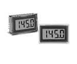
| 描述 | DPM +-20V LCD BACKLITE 5V-PWR数字面板表 +-20V / +5V Backlit Model |
| 产品分类 | |
| 品牌 | Murata Power Solutions |
| 产品手册 | |
| 产品图片 |
|
| rohs | RoHS 合规性豁免无铅 / 符合限制有害物质指令(RoHS)规范要求 |
| 产品系列 | 数字面板表,Murata Power Solutions DMS-20LCD-2-5B-CDMS-20LCD |
| 数据手册 | |
| 产品型号 | DMS-20LCD-2-5B-C |
| 产品种类 | 数字面板表 |
| 侵入防护 | - |
| 其它名称 | 811-2666 |
| 商标 | Murata Power Solutions |
| 外壳宽度 | 35 mm |
| 外壳长度 | 11 mm |
| 外壳高度 | 22 mm |
| 安装类型 | 面板安装 |
| 安装风格 | Panel, Board |
| 封装 | Bulk |
| 尺寸 | 11 mm L x 35 mm W x 22 mm H |
| 工作温度 | 0°C ~ 60°C |
| 工作电源电压 | 4.75 V to 5.25 V |
| 工作电源电流 | 35 mA |
| 工厂包装数量 | 12 |
| 描述/功能 | Low power |
| 显示器类型 | LCD, 3.5 Digit |
| 显示字符- 高度 | 0.370"(9.40mm) |
| 显示数字 | 3.5 |
| 显示样式 | 黑色字符,灰色背景 |
| 显示类型 | LCD - 黑色字符,浅绿背光 |
| 显示表面尺寸 | 1.83" 宽 x 1.28" 高 (46.4mm x 32.5mm) |
| 标准包装 | 12 |
| 校准 | 自校准 |
| 每行字符数 | 3.5 |
| 测量范围 | ±20VDC |
| 温度系数 | - |
| 特性 | - |
| 电压-电源 | 5VDC |
| 相关产品 | /product-detail/zh/DMS-EB2-C/811-1124-ND/1926167 |
| 端子类型 | PC 引脚 |
| 端接 | PC 引脚 |
| 类型 | 电压(电压表) |
| 精度 | - |
| 系列 | DMS-20LCD |
| 设备类型 | Voltmeters |
| 输入电压 | +/- 20 V |
| 输出类型 | - |
| 重量 | 0.025 磅(11.34g) |
| 零件号别名 | DMS-20LCD-2-5B-C |
| 面板开口尺寸 | 矩形 - 33.93mm x 21.29mm |


PDF Datasheet 数据手册内容提取
DMS-20LCD Series www.murata-ps.com 3½ Digit, LCD Display Digital Panel Voltmeters FEATURES DMS-20LCD Series, 3½ Digit, LCD Display, Digital Voltmeters represent the ultimate combination of low price, low power, small size and high performance in digital meters. Lowest cost Epoxy encapsulated in a subminiature (1.38” x 0.88” x 0.43”), 12-pin DIP package, these Lowest power, 2mW completely self-contained, fully operational meters offer a combination of ruggedness, Subminiature size: long-term reliability and component-like ease-of-use simply not available in any other 1.38" x 0.88" x 0.43" meters. 35mm x 22mm x 11mm Incorporating a precision reference and a factory-calibrated, autozeroing A/D converter, Large (0.37"/9.4mm), enhanced-contrast LCD display DMS-20LCD meters are extremely accurate (±1 count) and are only slightly larger than their 0.37"/9.4mm, enhanced-contrast, LCD displays. All models incorporate a built-in Epoxy-encapsulated, 12-pin DIP bezel and are easily mounted in either panels or pc boards. Both backlit and non-backlit Panel or pc-board mountable versions are available. 4 differential input voltage ranges DMS-20LCD meters have 4 differential input voltage ranges (±200mV, ±2V, ±20V and High accuracy, ±1 count (±0.05%) ±200V) and a user-friendly input structure. Input impedance is a minimum 800k. CMRR is typically 86dB with a CMV of ±2V. Non-inverting inputs are overvoltage protected to Single +5V supply or 9V battery ±100V (±250V for the ±200V input model). Low-battery annunciator All DMS-20LCD meters operate from a single +5V supply (drawing 400µA) or a single User-selectable decimal point placement +9V supply/battery (drawing 230µA). All models have a low-battery ("B") annunciator and 0 to +60°C temperature range feature autopolarity changeover and overrange indication. Also available is an application/evaluation board (DMS-EB2) that plugs directly onto the back of any DMS-20LCD allowing direct inputs for common applications such as 4-20mA inputs, zero/gain adjust, decimal point location, and input voltage dividing. SIMPLIFIED SCHEMATIC DIAGRAM +5V +5V SUPPLY/ 1 V+ 12 (–) INPUT LO +BATTERY 1 2 R2 –5V 0.01μF 2 DC/DC 3 R1 11 N.C. (+) INPUT HI CONVERTER V– 909k ≈+2.0V 5V RETURN/ 3 J1 A/D 10 ANALOG –BATTERY 0 Vdc CONVERTER COMMON DATA 4 9 DP 3 N.C./BACKLIGHT 4 5 8 DP 2 REFERENCE OUT +5V 6 7 DP 1 REFERENCE IN 1 R2 is not used on ±200mV (-0) models or ±2V (-1) models. 3 DC/DC converter is not used on 9V-powered models, R2 = 100k on ±20V (-2) models and 9.1k on ±200V (-3) models. J1 is connected. 2 Only used on ±200mV (-0) and ±2V (-1) models. 4 Used on backlit models only. N.C. for non-backlit models. For full details go to www.murata-ps.com/rohs www.murata-ps.com/support MPM_DMS20LCD.C01 Page 1 of 6
DMS-20LCD Series 3½ Digit, LCD Display Digital Panel Voltmeters Performance/Functional Specifi cations Typical at TA = +25°C and supply voltage = +5V (using the single-ended input circuit) or +9V (using the differential input circuit), unless otherwise noted. Analog Inputs Min. Typ. Max. Units Physical/Environmental Full Scale Input Range: Operating Temperature 0 – +60 °C DMS-20LCD-0 – ±200 – mV Storage Temperature –20 – +75 °C DMS-20LCD-1 – ±2 – Volts Humidity (non-condensing) 0 – 95 % DMS-20LCD-2 – ±20 – Volts Case Material Polycarbonate DMS-20LCD-3 – ±200 – Volts Weight 0.4 ounces (11 grams) Input Impedence: – ➀ Applies for transient or continuous overvoltages applied to (+) INPUT HI DMS-20LCD-0, -1 100 1000 – M (pin 11) with (–) INPUT LO (pin 12) properly connected. Pin 12 is not overvoltage DMS-20LCD-2, -3 0.8 1 – M protected (see Figure 1). Voltages applied to pin 12 should not exceed the Overvoltage Protection ➀ supply voltage. ➁ Listed spec applies to 5V-powered models only. For 9V-powered models, both DMS-20LCD-0, -1, -2 – – ±100 Volts (–) INPUT LO (pin 12) and (+) INPUT HIGH (pin 11) must always be at least DMS-20LCD-3 – – ±250 Volts 1.5V above –BATTERY (pin 3) and at least 1.5V below +BATTERY (pin 1). Common Mode Voltage Range – – ±2 Volts ➂See Technical Notes. CMRR (dc to 60Hz) – 86 – dB Ordering Information Control Inputs ➁ DMS-20LCD -1- 5 - C Decimal Pt. Placement (Pins 4-6) Tie to pin 3 to activate Functionality Tie to pin 3 to activate Add -C for RoHS Logic Compatibility TTL (on 5V-powered models) Input Range: Leave blank for standard Backlight (Pin 9) Tie to pin 3 to turn on backlight 0 = ±200mV models. 1 = ±2V Add B for backlit models. Performance 2 = ±20V Sampling Rate 2.5 reading per second 3 = ±200V Power Source: 5 = +5V Accuracy (1 minute warm-up): 9 = +9V Accessories: DMS-20PC-0 (Vin = +0.19V) – ±1 ±2 Counts DMS-20-CP Panel cutout punch DMS-20PC-1 (Vin = +1.9V) – ±1 ±2 Counts DMS-BZL3-C DMS-20 bezel assembly DMS-BZL4-C DMS-20 bezel assembly with sealing gasket DMS-20PC-2 (Vin = +19V) – ±2 ±3 Counts DMS-EB2-C Application/evaluation board with standard DMS-20PC-3 (Vin = +190V) – ±2 ±3 Counts MOLEX connector, decimal point solder pads Zero Reading (Vin = 0 Volts) “–001” “000” “001” and attenuation resistor pads. A panel-mount retaining clip is supplied with each model. Temperature Drift (0 = +60°C) – ±0.2 ±0.4 Cnts/°C Power Supply Requirements (5V Models) See www.murata-ps.com/dpm-availability for model-specifi c availability. Supply Voltage +4.75 +5.00 +5.25 Volts TECHNICAL NOTES Supply Current: Standard Models – +400 +650 µA 1. REFERENCE OUTPUT (Pin 8) and INPUT (Pin 7): Pin 8 is a precision Backlit Models – +35 +50 mA reference actively trimmed at the factory. In normal operation, pin 8 must be tied to pin 7 to achieve all listed accuracy and drift specifi ca- Power Supply Requirements (9V Models) tions. Supply Voltage +7.5 +9.0 +14.0 Volts 2. ANALOG COMMON (Pin 10): This pin is connected to an internal, Supply Current: low-noise, “relative” ground. It is used in certain differential and “fl oat- Standard Models – +230 +350 µA ing” measurements as described in the Applications section of this data Backlit Models – +35 +50 mA sheet and Ap Note DMS-AN3 at Display http://www.murata-ps.com/data/meters/dms-an3.pdf. Pin 10 should not be connected to pin 3 (5V RETURN/–BATTERY) or to your Display Type and Size 3½ digit, 0.37"/9.4mm high LCD system’s analog ground. Polarity Indication Autopolarity ("–" for negative Vin) 3. Decimal Point Placement: The location of the decimal point is user- Overrange Indication "–1___" for negative Vin selectable, and the decimal point control pins (DP1-DP3) are active low "1___" for positive Vin functions. Select the appropriate decimal point by tying the appropriate www.murata-ps.com/support MPM_DMS20LCD.C01 Page 2 of 6
DMS-20LCD Series 3½ Digit, LCD Display Digital Panel Voltmeters pin (pin 4, 5 or 6) to pin 3 (5V RETURN/–BATTERY). Unused decimal 8. Suggested Mating Connectors: point location pins should be left open. For 5V-powered models, the decimal location pins are TTL compatible and may be hard wired as Panel mounted: described above or driven with 5V TTL logic gates. Connector housing Murata Power Solutions P/N 4320-01069-0 4. BACKLIGHT (Pin 9) Function: Grounding pin 9 (i.e. connecting it to Terminal type Murata Power Solutions P/N 4400-01032-0 pin 3) turns on the backlighting LED’s. For non-backlit models, pin 9 Crimping tool Murata Power Solutions P/N 39-2099000 has no internal connection. All backlit models include internal current- Wire size 22 to 26 AWG limiting resistors. With nominal +5V or 9V supplies, backlit devices Insulation diameter 0.062” (1.57mm) maximum typically draw 35mA of supply current. The current drawn by the back- Stripping length 0.100 to 0.125” (2.54 to 3.17mm) light (and therefore the current drawn by the meter) can be reduced by installing a 1/4 Watt resistor between pins 3 and 9. The brightness of Board mounted: the meter will be reduced proportionately. Socket Murata Power Solutions P/N 4320-01074-0 9V-powered backlit models function with supply voltages up to +14V, APPLICATIONS however, activating the backlight with voltages greater than 9.2V can damage the meter. Therefore, a 1/4 Watt series resistor must be DMS-20LCD meters are available in either 5V-powered or 9V-powered installed between pins 3 and 9 in these situations. The value of the models. 9V devices operate directly from 7.5V to 14V supplies (usually series resistor is determined using the following formula: batteries) without the need for external voltage regulators. 9V devices, however, can not be used to measure voltages referenced to the negative +BATTERY – 9.2V battery terminal (pin 3) because the minus input to the meter (pin 12, (–) R = Ohms Series 0.035 INPUT LO) must always be at least 1.5V above pin 3. 9V-powered meters can only be used to make differential and not single-ended measurements. Example: If +BATTERY (pin 1 with respect to pin 3) is +12.6V, 5V-powered devices operate from any well-regulated +5V supply and will R = + 1 2 . 6 – 9 . 2 V Ohms accurately measure voltages both above and below pin 3 (5V RETURN) in Series 0.035 either single-ended or differential confi gurations. R = 97 Ohms Series 1. Single-Ended Input Confi gurations: True single-ended measure- ments can only be made with 5V-powered meters. The circuit of Figure 5. Low Battery Annunciator: The “B” annunciator in the upper left-hand 2 avoids problems normally associated with ground-loop currents. corner of the display turns on when the supply voltage for 5V-powered Separate ground runs should be used for 5V RETURN (pin 3) and (–) models falls below approximately +3.7V, or when the supply voltage for INPUT LO (pin 12). 9V-powered models falls below approximately 7.2V. However, the low- battery annunciator’s turn-on threshold can vary signifi cantly from unit- to-unit: as low as 2.7V for 5V-powered meters, and as low as 5.4V for DMS-20LCD-1-5 9V-powered models. Applications that use the LOW BAT annunciator 11 8 must be fully tested by the user, using a combination of low supply volt- + (+) IN HI REF OUT ages and the input signal’s minimum and maximum levels, to ensure VIN that all display readings are valid as long as the LOW BAT annunciator – 12 7 remains off. (–) IN LO REF IN 6. Gain Adjust: There is a gain-adjust potentiometer on the back of each 1 6 3 +5V SUP DP1 5V RET meter. It has approximately ±50 counts (±2.5%) range of adjustment. Since these devices essentially have no zero/offset errors, a gain adjustment is effectively an overall accuracy adjustment. Though they 120 VAC may be performed at any point (except zero), accuracy adjustments are most effective when performed with higher level input signals. The AC to DC Converter circuit shown in Figure 9 provides ±10% range of adjustment. Figure 2. Single-Ended Input Confi guration (5V-Powered Models) 7. Soldering Methods: All models in the DMS-20LCD Series easily withstand most common wave soldering operations. We recom- mend, however, that you evaluate the effects your particular soldering techniques may have on the meter’s plastic case and high-precision electrical performance. We recommend the use of no-clean solders. www.murata-ps.com/support MPM_DMS20LCD.C01 Page 3 of 6
DMS-20LCD Series 3½ Digit, LCD Display Digital Panel Voltmeters APPLICATIONS 2. Differential Input Confi gurations: Differential measurements can be 4. Floating Signal Source Measurements: Floating signals can be made with either 5V-powered or 9V-powered meters. Figure 3, though measured using the circuits shown in Figures 5 and 6. Figure 5 uses not a practical real-world application, uses a voltage divider to demon- a 5V-powered meter. Figure 6 uses a 9V-powered meter. Connecting strate the concept of a differential input signal. Be careful not to exceed pin 10 (ANALOG COMMON) to (–) INPUT LO (pin 12) provides the the ±2V common mode voltage limitation for 5V powered meters. reference point for the meter’s input. A “fl oating” input is a signal that has no galvanic connection to the meter’s power supply. In the fi gures below, the 1.5V battery illustrates a R1 DMS-20LCD-1-5 11 1k true fl oating input. REF OUT 8 (+) IN HI R2 REF IN 7 12 1k 11 DMS-20LCD-1-5 DP1 6 (–) IN LO (+) IN HI 8REF OUT + 1 3 R1k3 C1E.5LVL +5V SUP 5V RET – 12 7 (–) IN LO REF IN 120 VAC 1 3 6 +5V SUP 5V RET DP1 AC to DC Converter Figure 3. Differential Input Confi guration 120 VAC (5V-Powered Models) AC to DC Converter 3. Engineering Scaling: For measuring voltages greater than the full Figure 5. Floating Input Measurements scale input range of a given meter, the input signal must be attenuated. (5V-Powered Models) A simple voltage divider (similar to that shown in Figure 4) will scale the input to within the range of the selected meter. R1 and R2 should be precision, ±1%, metal-fi lm resistors with absolute TCR’s less than 50ppm/°C. See Ap Note 4 for more information on engineering scaling. DMS-20LCD-1-9 11 (+) IN HI 8 REF OUT 50k < R1 + R2 < 10M + 10 1.5V ANA COMM CELL R2 – x VIN = Reading 12 7 R1 + R2 (–) IN LO REF IN 1 3 6 + BAT –BAT DP1 + + 9V BATTERY R1 11 DMS-20LCD-1-5 – (+) IN HI 8 VIN REF OUT Figure 6. Floating Input Measurements (9V-Powered Models) R2 12 (–) IN LO – 7 5. Process Control (4-to-20mA) Measurements: In many common REF IN 1 3 process-control applications, a 4-to-20mA current loop is used to +5V SUP 5V RET transmit information. Because DMS-20LCD meters have such high input impedance, a simple shunt resistor across the meter’s input can 120 VAC be used to convert the loop current to a voltage. See Figure 7. The value of the shunt resistor is a function of the scaling requirements of AC to DC Converter the particular application and can be calculated using the following equation: Figure 4. Input Attenuation Circuit www.murata-ps.com/support MPM_DMS20LCD.C01 Page 4 of 6
DMS-20LCD Series 3½ Digit, LCD Display Digital Panel Voltmeters APPLICATIONS R = R1 = V /I Therefore, the 9V battery voltage appears to the meter inputs as 0.9V. Shunt Fsr Fsr With the decimal point moved to its DP2 position Where: V = Full scale reading (in Volts) (pin 5 tied to pin 3), the meter reads 9.00 Volts. Fsr I = Relative full scale current (in Amps) The circuit can be calibrated by fi rst measuring the actual battery volt- Fsr age with another meter and then adjusting the gain-adjust potentiom- Example: For a meter with a 2V full scale input (1.999 full eter on the back of the DMS-20LCD until a similar reading is obtained. scale reading) and a desired full scale display reading of If possible, the resistors in the divider should be ±1% metal-fi lm types 1000 (with an input of 20mA), V = 1.000 Volts with TCR’s less than 50ppm/°C. Fsr R = 1.000V/(0.020 – 0.004)A Shunt RShunt = 1.000V/0.016A = 62.5 Ohms DMS-20LCD-1-9 11 R1 To calibrate the circuit of Figure 7, perform the following: REF OUT 8 (+) IN HI 45.3k R2 1. With 4mA applied, adjust the 50k potentiometer (R2) to 12 10.1k (–) IN LO display a reading of "000" (assuming that is the desired REF IN 7 reading). 1 3 5 4R53.3k +BAT –BAT DP2 2. With 20mA applied, adjust the gain-adjust potentiometer on + 9V the back of the meter to display a reading of "1999". For different full BATTERY – scale readings, alter the value of R accordingly. Shunt Figure 8. Power Supply Monitor (9V-Powered Models) DMS-20LCD-1-5 11 + (+) IN 1H0I 8REF OUT 7. External Gain Adjustment: Connect REFERENCE OUT ANA COMM (pin 8) to REFERENCE IN (pin 7) for normal, factory calibrated, 12 operation. Use the circuit shown in Figure 9 for applications needing 4-20mA R1 7 (–) IN LO REF IN external gain adjustment. Calibration is performed with a precise, 1 3 near-full-scale, input voltage. R2 +5V SUP 5V RET – 50k 11 DMS-20LCD (+) IN HI 120 VAC OUT 3 VOLTAGE 5V RET/ 1 AC to DC Converter 12CALIBRATOR –BAT IN +5V IN/ Figure 7. 4-to-20mA Current Loop Operation 12 +BAT IN (5V-Powered Models) COM (–) IN LO Connections for ±2V, ±20V 10 8 7 and ±200V models ANA NC REF COMM IN 6. Power Supply Monitoring: A popular application for Murata Power 8.06k, 1% 2k 17.4k, 1% Solutions’ low-power LCD meters is monitoring the supply voltage in battery-operated portable equipment. Figure 8 demonstrates how a 9V-powered DMS-20LCD can be used to monitor its own supply. The For +5V models, tie (–) IN LO to pin 3. Connections For +9V models, tie (–) IN LO to pin 10 for ±200mV meter used is the DMS-20LCD-1-9. A three-resistor voltage divider is models 732, 1% 200 24.3k, 1% used to attenuate the battery voltage and also to satisfy the require- = 10 to 20 Turns ment that the input voltages applied to pins 12 and 11 be at least 1.5 Volts above and below the battery voltage applied to pins 1 (+BAT- Figure 9. External Gain Adjustment TERY) and 3 (–BATTERY). The divider should be designed so that 1/10th the battery voltage falls across the inputs to the meter: R2 = 0.1 (R1 + R2 + R3) www.murata-ps.com/support MPM_DMS20LCD.C01 Page 5 of 6
DMS-20LCD Series 3½ Digit, LCD Display Digital Panel Voltmeters MECHANICAL SPECIFICATIONS MECHANICAL DIMENSIONS: Inches (mm) TOLERANCES: 2 PL DEC ±0.02 (±0.51) 3 PL DEC ±0.010 (±0.254) IDENTPIIFNIE #R1 XX-X-DCL02-SMD LEAD DIMENSIONS: 0.025 (0.635) x 0.025 (0.635) NOMINAL RECOMMENDED PC BOARD FINISHED HOLE DIAMETER: 0.042 ±0.003 (1.067 ±0.076) CALIBRATION POTENTIOMETER HOLE LOCATION FRONT VIEW PIN 1 0.160 +5V SUPPLY/ +BATTERY 1 12 (–) INPUT LO (4.06) N.C. 2 11 (+) INPUT HI 5V RETURN/ –BATTERY 3 10 ANALOG COMMON DP3 4 9 N.C./BACKLIGHT DP2 5 8 REFERENCE OUT DP1 6 7 REFERENCE IN 0.160 DP1 DP2 DP3 (4.06) 0.88 1.38 (22.3) (35.1) 0.125 (3.175) DIAMETER (USE ONLY WHEN PC 0.80 1.30 BOARD MOUNTING) (20.3) (33.0) 0.425 (10.80) 0.040 (1.02) 0.25 (6.4) TYP. 0.040 (1.02) 0.10 1.10 0.10 (03.1.85) T(2Y.5P). 0.040 (27.9) T(2Y.5P). TYP. (1.02) 0.50 (12.7) BEZEL INSTALLATION AND RECOMMENDED DRILL AND PANEL CUTOUT OPTIONAL BEZEL (DMSBZL3 and DMSBZL4) #2-56 INSERT 0.187 BEZEL INSTALLATION 0.156 (3.96) DEEP (4.75) FRONT VIEW PANEL 1.280 (32.51) 1.826 (46.38) BEZEL RECOMMENDED DRILL AND PANEL CUTOUT DIMENSIONS INTERNAL CORNER RADII: 0.032 (0.81) MAX. RETAINING CLIP INSTALLATION 1.07 0.838 (27.18) (21.29) 1.336 (33.93) (03.1.6485) PANEL 1.626 (41.30) 0.116 0.093 (2.362) DIAMETER (4 REQUIRED) (2.95) ONLY WHEN USING OPTIONAL BEZEL ASSEMBLY This product is subject to the following operating requirements Murata Power Solutions, Inc. and the Life and Safety Critical Application Sales Policy: 11 Cabot Boulevard, Mansfi eld, MA 02048-1151 U.S.A. Refer to: http://www.murata-ps.com/requirements/ ISO 9001 and 14001 REGISTERED Murata Power Solutions, Inc. makes no representation that the use of its products in the circuits described herein, or the use of other technical information contained herein, will not infringe upon existing or future patent rights. The descriptions contained herein do not imply the granting of licenses to make, use, or sell equipment constructed in accordance therewith. Specifi cations are subject to change without notice. © 2015 Murata Power Solutions, Inc. www.murata-ps.com/support MPM_DMS20LCD.C01 Page 6 of 6
Mouser Electronics Authorized Distributor Click to View Pricing, Inventory, Delivery & Lifecycle Information: M urata: DMS-20LCD-3-5B DMS-20LCD-3-9B DMS-20LCD-2-5B DMS-20LCD-2-9B DMS-20LCD-0-5B-C DMS-20LCD-0-5- C DMS-20LCD-0-9B-C DMS-20LCD-0-9-C DMS-20LCD-1-5B-C DMS-20LCD-1-5-C DMS-20LCD-1-9B-C DMS- 20LCD-1-9-C DMS-20LCD-2-5B-C DMS-20LCD-2-5-C DMS-20LCD-2-9B-C DMS-20LCD-2-9-C DMS-20LCD-3-5B-C DMS-20LCD-3-5-C DMS-20LCD-3-9B-C DMS-20LCD-3-9-C DMS-20LCD-3-5 DMS-20LCD-3-9 DMS-20LCD-1-9B DMS-20LCD-1-5B DMS-20LCD-2-5 DMS-20LCD-2-9 DMS-20LCD-0-9 DMS-20LCD-0-5 DMS-20LCD-1-9 DMS- 20LCD-1-5 DMS-20LCD-0-9B DMS-20LCD-0-5B