 Datasheet下载
- 型号: DLP11TB800UL2L
- 制造商: Murata
- 库位|库存: xxxx|xxxx
- 要求:
| 数量阶梯 | 香港交货 | 国内含税 |
| +xxxx | $xxxx | ¥xxxx |
查看当月历史价格
查看今年历史价格
DLP11TB800UL2L产品简介:
ICGOO电子元器件商城为您提供DLP11TB800UL2L由Murata设计生产,在icgoo商城现货销售,并且可以通过原厂、代理商等渠道进行代购。 DLP11TB800UL2L价格参考¥1.18-¥1.56。MurataDLP11TB800UL2L封装/规格:共模扼流圈, 2 线 共模扼流圈 表面贴装 80 Ohms @ 100MHz 100mA DCR 1.88 欧姆。您可以下载DLP11TB800UL2L参考资料、Datasheet数据手册功能说明书,资料中有DLP11TB800UL2L 详细功能的应用电路图电压和使用方法及教程。
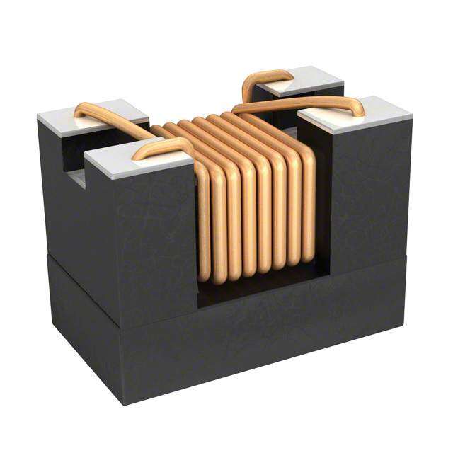
Murata Electronics North America 生产的型号为 DLP11TB800UL2L 的共模扼流圈(Common Mode Choke),主要用于抑制差分信号线上的共模噪声,同时保持信号完整性。以下是其典型应用场景:

 1. 高速数据传输接口
   - 适用于高速差分信号接口,例如 USB 3.0/3.1、HDMI、DisplayPort 和 SATA 等。
   - 在这些接口中,DLP11TB800UL2L 能有效滤除高频共模噪声,确保数据传输的稳定性和可靠性。

 2. 汽车电子系统
   - 用于车载信息娱乐系统(如导航、音响等)和 CAN 总线通信。
   - 抑制汽车电子设备中的电磁干扰(EMI),保护敏感电路免受外界干扰。

 3. 工业自动化设备
   - 应用于工业控制中的 RS-485、RS-232 和 Ethernet 接口。
   - 减少工业环境中强电磁场对通信线路的影响,提高系统的抗干扰能力。

 4. 消费类电子产品
   - 用于笔记本电脑、平板电脑和智能手机的外部接口(如 USB-C、Thunderbolt)。
   - 防止外部设备连接时引入的噪声干扰内部电路。

 5. 网络通信设备
   - 在路由器、交换机和网卡中使用,用于保护以太网接口。
   - 消除因长距离传输或复杂电磁环境引起的共模噪声。

 6. 医疗设备
   - 用于医疗监测设备(如心电图仪、超声波设备)的信号传输部分。
   - 确保高精度信号不受外界电磁干扰的影响。

 特性优势:
- 高共模抑制比:有效滤除共模噪声,同时对差模信号影响较小。
- 低插入损耗:在高频段保持信号完整性,减少能量损失。
- 小型化设计:适合现代电子设备对紧凑空间的需求。
- 宽频率范围:适用于多种高频应用场合。

综上所述,DLP11TB800UL2L 是一款高性能共模扼流圈,广泛应用于需要高速数据传输和抗干扰能力的场景中,能够显著提升系统的稳定性和可靠性。
| 参数 | 数值 |
| 产品目录 | |
| DC电阻(DCR) | 1.5 欧姆 |
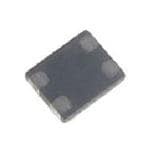
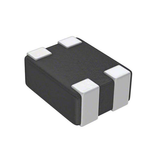
| 描述 | CHOKE COIL COMMON MODE 100MA SMD共模滤波器/扼流器 0504 80ohm EMI Suppression Fltr |
| 产品分类 | |
| 品牌 | Murata Electronics North America |
| 产品手册 | |
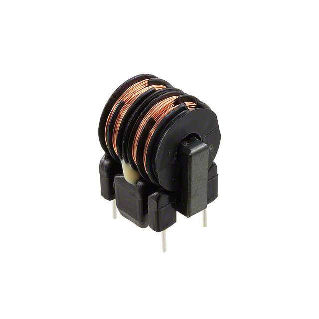
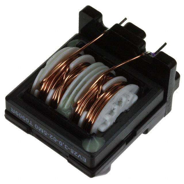
| 产品图片 |
|
| rohs | 符合RoHS无铅 / 符合限制有害物质指令(RoHS)规范要求 |
| 产品系列 | 共模滤波器/扼流器,Murata Electronics DLP11TB800UL2LEMIFIL®, DLP11T |
| mouser_ship_limit | 该产品可能需要其他文件才能进口到中国。 |
| 数据手册 | |
| 产品型号 | DLP11TB800UL2L |
| 产品 | Common Mode Filters |
| 产品种类 | 共模滤波器/扼流器 |
| 其它名称 | 490-5574-6 |
| 包装 | Digi-Reel® |
| 商标 | Murata Electronics |
| 外壳宽度 | 1 mm |
| 外壳长度 | 1.25 mm |
| 外壳高度 | 0.3 mm |
| 大小/尺寸 | 0.049" 长 x 0.039" 宽(1.25mm x 1.00mm) |
| 安装类型 | 表面贴装 |
| 容差 | 25 % |
| 封装 | Reel |
| 封装/外壳 | 0504(1210 公制),4 引线 |
| 封装/箱体 | 0504 (1210 metric) |
| 尺寸 | 1 mm W x 1.25 mm L x 0.3 mm H |
| 工作温度 | -40°C ~ 85°C |
| 工作温度范围 | - 40 C to + 85 C |
| 工厂包装数量 | 5000 |
| 最大直流电流 | 100 mA |
| 标准包装 | 1 |
| 滤波器类型 | 数据,信号线 |
| 电感 | - |
| 电流 | 100mA |
| 端接类型 | SMD/SMT |
| 线路数 | 2 |
| 阻抗 | 80 欧姆 |
| 高度(最大值) | 0.014"(0.35mm) |


- 商务部:美国ITC正式对集成电路等产品启动337调查
- 曝三星4nm工艺存在良率问题 高通将骁龙8 Gen1或转产台积电
- 太阳诱电将投资9.5亿元在常州建新厂生产MLCC 预计2023年完工
- 英特尔发布欧洲新工厂建设计划 深化IDM 2.0 战略
- 台积电先进制程称霸业界 有大客户加持明年业绩稳了
- 达到5530亿美元!SIA预计今年全球半导体销售额将创下新高
- 英特尔拟将自动驾驶子公司Mobileye上市 估值或超500亿美元
- 三星加码芯片和SET,合并消费电子和移动部门,撤换高东真等 CEO
- 三星电子宣布重大人事变动 还合并消费电子和移动部门
- 海关总署:前11个月进口集成电路产品价值2.52万亿元 增长14.8%
PDF Datasheet 数据手册内容提取
Noise Suppression Products/EMI Suppression Filters > Common Mode Choke Coil > Film Type Data Sheet 11 Common Mode Choke Coil Film Type DLP11S/DLP11R/DLP11T Series (0504 Size) c Dimensions c Equivalent Circuit 0.3±0.1 T (1) (2) Part Number T (1) (2) DLP11S 0.82±0.1 0.55±0.1 (3) 1.0±0.1 DDLLPP1111RT 00..35±±00..015 (4) (3) (4) 0.25+–00..015 No polarity. : Electrode 1.25±0.1 (in mm) c Impedance-Frequency Characteristics (Main Items) c Impedance-Frequency Characteristics (Main Items) DLP11SN Series DLP11SA Series 10000 1000 Common mode DLP11SN331HL2 1000 DLP11SN281HL2 Common mode DLP11SN241HL2 100 Ω) DLP11SN201HL2 Ω) Impedance ( 100 DLDPL1P1DS1LD1NPSL61PN71019SS10NS0L1H2N2L1126S1LS2L2 DLDPL1DP11SL1PNS12N14S21N8H13LH321LH2L2 Impedance ( 10 DDLPLDP1L11PS11SA1A3S56A079H00HL02LH2L2 10 DLP11SN201HL2 DLP11SN161SL2 DLP11SA900HL2 DLP11SN121SL2 DLP11SA670HL2 DLP11SN900HL2 DLP11SA350HL2 DLP11SN670SL2 Differential mode Differential mode 1 1 1 10 100 1000 10000 1 10 100 1000 10000 Frequency (MHz) Frequency (MHz) c Impedance-Frequency Characteristics (Main Items) c Impedance-Frequency Characteristics (Main Items) DLP11RN Series DLP11RB Series 1000 1000 Common mode Common mode DLP11RB150UL2 100 100 DLP11RB400UL2 Ω) Ω) mpedance ( DLP11RN450UL2 mpedance ( I 10 DLP11RN450UL2 I 10 DLP11RB150UL2 Differential mode DLP11RB400UL2 Differential mode 1 1 1 10 100 1000 10000 1 10 100 1000 10000 Frequency (MHz) Frequency (MHz) Continued on the following page. oThis data sheet is applied for CHIP COMMON MODE CHOKE COIL used for General Electronics equipment for your design. !Note: 1. This datasheet is downloaded from the website of Murata Manufacturing co., ltd. Therefore, it’s specifi cations are subject to change or our products in it may be discontinued without advance notice. Please check with our sales representatives or product engineers before ordering. 2. This datasheet has only typical specifi cations because there is no space for detailed specifi cations. Therefore, please approve our product specifi cations or transact the approval sheet for product specifi cations before ordering. 2011.9.8 http://www.murata.com/
Noise Suppression Products/EMI Suppression Filters > Common Mode Choke Coil > Film Type Data Sheet 22 Continued from the preceding page. c Impedance-Frequency Characteristics (Main Items) DLP11TB Series 1000 Common mode 100 Ω) DLP11TB800UL2 mpedance ( I 10 DLP11TB800UL2 Differential mode 1 1 10 100 1000 10000 Frequency (MHz) c Differential Mode Transmission Characteristics (Typ.) c Differential Mode Transmission Characteristics (Typ.) DLP11SN Series DLP11SA Series 0 0 DLP11SA900HL2 2 2 DLP11SN900HL2 B) B) Insertion Loss (d 46 Insertion Loss (d 46 8 8 10 10 1 10 100 1000 10000 1 10 100 1000 10000 Frequency (MHz) Frequency (MHz) c Differential Mode Transmission Characteristics (Typ.) c Differential Mode Transmission Characteristics (Typ.) DLP11RN Series DLP11RB Series 0 0 2 2 DLP11RN450UL2 DLP11RB400UL2 B) B) Insertion Loss (d 64 Insertion Loss (d 64 8 8 10 10 1 10 100 1000 10000 1 10 100 1000 10000 Frequency (MHz) Frequency (MHz) Continued on the following page. oThis data sheet is applied for CHIP COMMON MODE CHOKE COIL used for General Electronics equipment for your design. !Note: 1. This datasheet is downloaded from the website of Murata Manufacturing co., ltd. Therefore, it’s specifi cations are subject to change or our products in it may be discontinued without advance notice. Please check with our sales representatives or product engineers before ordering. 2. This datasheet has only typical specifi cations because there is no space for detailed specifi cations. Therefore, please approve our product specifi cations or transact the approval sheet for product specifi cations before ordering. 2011.9.8 http://www.murata.com/
Noise Suppression Products/EMI Suppression Filters > Common Mode Choke Coil > Film Type Data Sheet 33 Continued from the preceding page. c Differential Mode Transmission Characteristics (Typ.) c Packaging DLP11TB Series Code Packaging Minimum Quantity 3000 (DLP11S) 0 L 180mm Embossed Tape 4000 (DLP11RN/RB) DLP11TB800UL2 2 5000 (DLP11T) B Bulk(Bag) 500 B) Insertion Loss (d 64 8 10 1 10 100 1000 10000 Frequency (MHz) c Rated Value (p: packaging code) Common Mode Impedance Operating Part Number Rated Current Rated Voltage Insulation Resistance (min.) Withstand Voltage DC Resistance (at 100MHz/20°C) Temperature Range DLP11SN670SL2p 67ohm ±20% 180mA 5Vdc 100M ohm 12.5Vdc 1.3ohm±25% -40 to +85°C DLP11SN121SL2p 120ohm ±20% 140mA 5Vdc 100M ohm 12.5Vdc 2.0ohm±25% -40 to +85°C DLP11SN161SL2p 160ohm ±20% 120mA 5Vdc 100M ohm 12.5Vdc 2.7ohm±25% -40 to +85°C DLP11SN900HL2p 90ohm ±20% 150mA 5Vdc 100M ohm 12.5Vdc 1.5ohm±25% -40 to +85°C DLP11SN201HL2p 200ohm ±20% 110mA 5Vdc 100M ohm 12.5Vdc 3.1ohm±25% -40 to +85°C DLP11SN241HL2p 240ohm ±20% 100mA 5Vdc 100M ohm 12.5Vdc 3.5ohm±25% -40 to +85°C DLP11SN281HL2p 280ohm ±20% 90mA 5Vdc 100M ohm 12.5Vdc 4.2ohm±25% -40 to +85°C DLP11SN331HL2p 330ohm ±20% 80mA 5Vdc 100M ohm 12.5Vdc 4.9ohm±25% -40 to +85°C DLP11SA350HL2p 35ohm ±20% 170mA 5Vdc 100M ohm 12.5Vdc 0.9ohm±25% -40 to +85°C DLP11SA670HL2p 67ohm ±20% 150mA 5Vdc 100M ohm 12.5Vdc 1.2ohm±25% -40 to +85°C DLP11SA900HL2p 90ohm ±20% 150mA 5Vdc 100M ohm 12.5Vdc 1.4ohm±25% -40 to +85°C DLP11RN450UL2p 45ohm ±25% 100mA 5Vdc 100M ohm 12.5Vdc 0.8ohm±25% -40 to +85°C DLP11RB150UL2p 15ohm ±5ohm 100mA 5Vdc 100M ohm 12.5Vdc 0.8ohm±25% -40 to +85°C DLP11RB400UL2p 40ohm ±10ohm 100mA 5Vdc 100M ohm 12.5Vdc 1.3ohm±25% -40 to +85°C DLP11TB800UL2p 80ohm ±25% 100mA 5Vdc 100M ohm 12.5Vdc 1.5ohm±25% -40 to +85°C Number of Circuit: 1 Differential mode to common mode conversion characteristic (Scd21) at 2.5GHz DLP11RB/TB: -40dB Impedance Characteristics between signal lines Z0 (TDR at 50ps) DLP11RB/TB: 90ohm±15ohm c !Caution/Notice !Caution (Rating) Notice Do not use products beyond the rated current and Solderability of Tin plating termination chip might be rated voltage as this may create excessive heat deteriorated when low temperature soldering profi le and deteriorate the insulation resistance. where peak solder temperature is below the Tin melting point is used. Please confi rm the solderability of Tin plating termination chip before use. oThis data sheet is applied for CHIP COMMON MODE CHOKE COIL used for General Electronics equipment for your design. !Note: 1. This datasheet is downloaded from the website of Murata Manufacturing co., ltd. Therefore, it’s specifi cations are subject to change or our products in it may be discontinued without advance notice. Please check with our sales representatives or product engineers before ordering. 2. This datasheet has only typical specifi cations because there is no space for detailed specifi cations. Therefore, please approve our product specifi cations or transact the approval sheet for product specifi cations before ordering. 2011.9.8 http://www.murata.com/