 Datasheet下载
- 型号: DLW21SN261SQ2L
- 制造商: Murata
- 库位|库存: xxxx|xxxx
- 要求:
| 数量阶梯 | 香港交货 | 国内含税 |
| +xxxx | $xxxx | ¥xxxx |
查看当月历史价格
查看今年历史价格
DLW21SN261SQ2L产品简介:
ICGOO电子元器件商城为您提供DLW21SN261SQ2L由Murata设计生产,在icgoo商城现货销售,并且可以通过原厂、代理商等渠道进行代购。 DLW21SN261SQ2L价格参考。MurataDLW21SN261SQ2L封装/规格:共模扼流圈, 2 线 共模扼流圈 表面贴装 260 Ohms @ 100MHz 300mA DCR 400 毫欧。您可以下载DLW21SN261SQ2L参考资料、Datasheet数据手册功能说明书,资料中有DLW21SN261SQ2L 详细功能的应用电路图电压和使用方法及教程。
Murata Electronics North America生产的DLW21SN261SQ2L是一款共模扼流圈(Common Mode Choke),主要用于抑制和过滤电子设备中的共模噪声。以下是其典型的应用场景:

 1. 电源线噪声抑制
   - 该型号适用于电源线路中,用于抑制从电源线传导的共模噪声。它能够有效减少电磁干扰(EMI),确保设备符合EMC标准。
   - 常见应用:电脑、服务器、工业设备、家用电器等的电源输入端。

 2. 通信接口保护
   - 在通信接口(如USB、以太网、HDMI等)中,DLW21SN261SQ2L可以滤除信号线上的共模噪声,同时保持差模信号的完整性。
   - 常见应用:网络设备、数据传输设备、消费类电子产品。

 3. 汽车电子系统
   - 该共模扼流圈可用于汽车电子系统中,例如车载信息娱乐系统、CAN总线、LIN总线等,以减少电磁干扰对敏感电子组件的影响。
   - 特点:能够在较高温度和振动环境下稳定工作。

 4. 工业自动化设备
   - 在工业环境中,共模扼流圈被广泛应用于变频器、伺服驱动器、PLC控制器等设备中,用以降低共模噪声对系统稳定性的影响。
   - 常见应用:工厂自动化、机器人控制、传感器接口。

 5. 消费类电子产品
   - DLW21SN261SQ2L适合用于智能手机、平板电脑、笔记本电脑等便携式设备的充电接口或信号传输接口中,以提高抗干扰能力。
   - 特点:小型化设计,适合紧凑型电路板布局。

 6. 医疗设备
   - 在高精度医疗设备中,该型号可帮助减少噪声干扰,确保信号采集和传输的准确性。
   - 常见应用:监护仪、超声设备、心电图机等。

 技术特点:
- 高共模噪声抑制能力:能有效滤除高频噪声。
- 低差模插入损耗:对正常信号的影响较小。
- 小型化设计:适合现代电子产品的紧凑设计需求。
- 高可靠性:能在严苛环境下长期稳定工作。

总结来说,DLW21SN261SQ2L适用于需要高性能噪声抑制的各种电子设备,特别是在对EMI敏感或要求高可靠性的应用场景中表现优异。
| 参数 | 数值 |
| 产品目录 | |
| DC电阻(DCR) | 400 毫欧最大 |
| 描述 | CHOKE COIL COMMON MODE 300MA SMD共模滤波器/扼流器 0805 260ohm 50volt DCR 0.40ohm |
| 产品分类 | |
| 品牌 | Murata Electronics North America |
| 产品手册 | |
| 产品图片 |
|
| rohs | 符合RoHS无铅 / 符合限制有害物质指令(RoHS)规范要求 |
| 产品系列 | 共模滤波器/扼流器,Murata Electronics DLW21SN261SQ2LEMIFIL®, DLW21S |
| 数据手册 | |
| 产品型号 | DLW21SN261SQ2L |
| 产品 | Common Mode Chokes |
| 产品培训模块 | http://www.digikey.cn/PTM/IndividualPTM.page?site=cn&lang=zhs&ptm=19298 |
| 产品目录绘图 |
|
| 产品目录页面 | |
| 产品种类 | 共模滤波器/扼流器 |
| 其它名称 | 490-5140-1 |
| 包装 | 剪切带 (CT) |
| 单位重量 | 11 mg |
| 商标 | Murata Electronics |
| 外壳宽度 | 1.2 mm |
| 外壳长度 | 2 mm |
| 外壳高度 | 0.9 mm |
| 大小/尺寸 | 0.079" 长 x 0.047" 宽(2.00mm x 1.20mm) |
| 安装类型 | 表面贴装 |
| 容差 | 25 % |
| 封装 | Reel |
| 封装/外壳 | 水平式,4 PC 板 |
| 封装/箱体 | 0805 (2012 metric) |
| 尺寸 | 1.2 mm W x 2 mm L x 0.9 mm H |
| 屏蔽 | Unshielded |
| 工作温度 | -40°C ~ 85°C |
| 工作温度范围 | - 40 C to + 85 C |
| 工厂包装数量 | 2000 |
| 最大直流电流 | 300 mA |
| 最大直流电阻 | 400 mOhms |
| 标准包装 | 1 |
| 测试频率 | 100 MHz |
| 滤波器类型 | 数据,信号线 |
| 特色产品 | http://www.digikey.com/cn/zh/ph/Murata/ChokeCoils.html |
| 电感 | - |
| 电流 | 300mA |
| 端接类型 | SMD/SMT |
| 类型 | Wirewound |
| 系列 | DLW21H |
| 线路数 | 2 |
| 阻抗 | 260 欧姆 |
| 高度(最大值) | 0.055"(1.40mm) |


- 商务部:美国ITC正式对集成电路等产品启动337调查
- 曝三星4nm工艺存在良率问题 高通将骁龙8 Gen1或转产台积电
- 太阳诱电将投资9.5亿元在常州建新厂生产MLCC 预计2023年完工
- 英特尔发布欧洲新工厂建设计划 深化IDM 2.0 战略
- 台积电先进制程称霸业界 有大客户加持明年业绩稳了
- 达到5530亿美元!SIA预计今年全球半导体销售额将创下新高
- 英特尔拟将自动驾驶子公司Mobileye上市 估值或超500亿美元
- 三星加码芯片和SET,合并消费电子和移动部门,撤换高东真等 CEO
- 三星电子宣布重大人事变动 还合并消费电子和移动部门
- 海关总署:前11个月进口集成电路产品价值2.52万亿元 增长14.8%
PDF Datasheet 数据手册内容提取
SMD/BLOCK Type EMI Suppression Filters EMIFIL
Introduction Murata Manufacturing Co., Ltd. has been developing the EMI suppression device market since the invention of 3 terminal capacitor DS310 series in 1979. Also, we have been striving to develop and popularize new noise countermeasure technologies as well as new products in the concept of "Develop unique products," to become our customer’s best solution partner. We hope you can find the key solution to your noise problem. Explanation of symbols in this catalog Features of each series Features of each item All Products New product Flow soldering available FlowOK Exist in design kit Rated current 1A or more Reflow Reflow soldering available OK Rated current 3A or more Rated current 10A or more Meets large current lines Chip Ferrite Bead Meets high frequency noise up to 1-2GHz Meets ultra high frequency noise up to 10GHz Low cut-off frequency type for UHF band LC Combined Type Filter noise, which affects digital TV tuner For high speed differential signal lines Chip Common Mode Choke Coil (USB2.0/LVDS/IEEE1394 etc.) For ultra high speed differential signal lines (HDMI/DVI/Display Port/USB3.0 etc.) Line impedance has been matched to transmission lines EU RoHS Compliant (cid:115) All the products in this catalog comply with EU RoHS. (cid:115) EU RoHS is "the European Directive 2011/65/EU on the Restriction of the Use of Certain Hazardous Substances in Electrical and Electronic Equipment." (cid:115) For more details, please refer to our website 'Murata's Approach for EU RoHS' (http://www.murata.com/info/rohs.html). !Note(cid:129) Please read rating and !CAUTION (for storage, operating, rating, soldering, mounting and handling) in this catalog to prevent smoking and/or burning, etc. (cid:129) This catalog has only typical specifi cations. Therefore, please approve our product specifi cations or transact the approval sheet for product specifi cations before ordering. 2
CONTENTS Selection Guide for Noise Suppression Filters············ 2 EMI Filter Selection by Application ···························· 4 aDigital Still Camera······4 aSmartphone·········5 aBlu-ray/DVD···············6 aLCD-TV···············7 EMI Filter Selection by Circuits and Noise Frequency··· 8 Product Guide ························································· 10 BL p Chip Ferrite Bead Series Introduction·················································· 14 Part Numbering······················································· 16 ad Series Line Up························································· 18 Be P!rCodauuctito Dn/eNtaoitlic··e············································································································ 2949 errite F Soldering and Mounting··········································· 100 hip Packaging ······························································ 104 C Design Kits····························································· 105 NF p Chip EMIFILr Series Introduction·················································· 112 Part Numbering······················································· 114 r Series Line Up························································· 117 L FI Product Detail························································· 121 MI !Caution/Notice····················································· 154 p E Soldering and Mounting··········································· 156 Chi Packaging ······························································ 163 Design Kits····························································· 165 DL p/PLp Chip Common Mode Choke Coil oil C Series Introduction·················································· 170 e k Part Numbering······················································· 172 ho C Series Line Up························································· 174 e d Product Detail························································· 177 o M !Caution/Notice····················································· 203 n o Soldering and Mounting··········································· 205 m m Packaging ······························································ 212 o C Design Kits····························································· 214 p hi C BNX Block Type EMIFILr Series Line Up························································· 218 r Function Example ··················································· 218 L FI Product Detail························································· 221 MI !Caution/Notice····················································· 225 e E p Soldering and Mounting··········································· 227 y T Packaging ······························································ 231 k c o Design Kits····························································· 232 Bl EA Microwave Absorber Part Numbering······················································· 234 er Product Detail························································· 235 b or Notice ···································································· 238 s b A Product Guide by Size ············································· 239 ve Part Number Quick Reference ································· 240 wa Alphabetic Product Name Index ······························ 240 cro Mi Introduction of Related Catalogs ······························ 241 Introduction of EMI/MLCC/Inductor special web site "EMICON-FUN!"··········· 242 !Note(cid:129) Please read rating and !CAUTION (for storage, operating, rating, soldering, mounting and handling) in this catalog to prevent smoking and/or burning, etc. (cid:129) This catalog has only typical specifi cations. Therefore, please approve our product specifi cations or transact the approval sheet for product specifi cations before ordering. 1
SSeelleeccttiioonn GGuuiiddee ffoorr NNooiissee SSuupppprreessssiioonn FFiilltteerrss oFeatures & Suitable Circuits Type Features Suitable Circuits Ferrite Bead BLM/BLA Series · Miniaturized · Application set with less · GND connection unnecessary noise radiation · Effective at low impedance line · Low impedance line Capacitor Type · Application set with higher NFM/NFA/NFE/NFR/ · Great noise suppression effect noise radiation NFL/NFW Series · With effect as By-Pass capacitor (Lineup for Power) · High impedance line · Good noise separation from signal (LC filter for Signal) · Circuit with By-Pass capacitor · Effective at high impedance line · Circuit driven by high frequency Common Mode · Possible to suppress noise with less affect of ultra · High speed differential Choke Coil high speed signal signal line · Great effect for common mode noise · I/F cable driver · Less magnetic saturation by current · Power line oExample Common Mode Choke Coil Ferrite Bead Inductor Suppresses common mode noise. Suppresses differential mode noise. Common Mode Choke Coil Suppresses common mode noise. Vcc DC power supply USB/IEEE1394 input section GND Three-terminal Capacitor Suppresses differential mode noise. !Note(cid:129) Please read rating and !CAUTION (for storage, operating, rating, soldering, mounting and handling) in this catalog to prevent smoking and/or burning, etc. (cid:129) This catalog has only typical specifi cations. Therefore, please approve our product specifi cations or transact the approval sheet for product specifi cations before ordering. 2
SSeelleeccttiioonn GGuuiiddee ffoorr NNooiissee SSuupppprreessssiioonn FFiilltteerrss oAdvantages to Using Common Mode Choke Coils 1. Great Effect for Common Mode Noise Differential mode inductors work as a half Ex) 2pcs of differential mode inductor impedance for common mode noise. Common Mode Choke Coils are effective for Z common mode noise. Noise source ~ d a o L Z N Stray capacitance Stray capacitance Reference ground surface 2. Possible to Suppress Noise with Less Affect of Ultra High Speed Signal Common Mode Choke Coils can suppress Noise with less affect of Signal, even if the frequency range of Signal and Noise are the same, because they separate each conductive mode of current. Usingdifferential mode Signal is attenuated Signal spectrum Noise spectrum inductor with Noise suppression (Differential mode) (Common mode) Frequency Noise is suppressed Frequency Using Common Mode with less effect on Choke Coil Signal Frequency 3. Less Magnetic Saturation by Current Common Mode Choke Coils are effective for noise suppression of DC power lines, due to their less magnetic saturation at high power current, that comes from their construction of cancelling magnetic flux of differential mode current at each coil. !Note(cid:129) Please read rating and !CAUTION (for storage, operating, rating, soldering, mounting and handling) in this catalog to prevent smoking and/or burning, etc. (cid:129) This catalog has only typical specifi cations. Therefore, please approve our product specifi cations or transact the approval sheet for product specifi cations before ordering. 3
EEMMII FFiilltteerr SSeelleeccttiioonn bbyy AApppplliiccaattiioonn Digital Still Camera Application Sample Data Line IC Power Line Data Line BLM**B/BLA**B BLM**P/BLM**AX BLM**B/BLA**B p26 p24 p26 p80 p27 p80 DLP0NS p187 NFM**P* p123 Flash Memory Lens Image Sensor Image LCD LCD Controller Sensor Controler Panel A/D Converter CPU (DSP,JPEG) Speaker Lens Motor Audio Motor Driver Processer MCU USB I/F Card Microphone Slot AC Adapter Power Unit USB Differential Data Line DLM11S p185 Battery Storage Media DLP0QS/DLP0NS/11S Power Line p186 AC Adapter Input p187 BLM**P/BLM**AX p189 DLW5 p179 p24 p181 p27 NFM**P* p123 !Note(cid:129) Please read rating and !CAUTION (for storage, operating, rating, soldering, mounting and handling) in this catalog to prevent smoking and/or burning, etc. (cid:129) This catalog has only typical specifi cations. Therefore, please approve our product specifi cations or transact the approval sheet for product specifi cations before ordering. 4
EEMMII FFiilltteerr SSeelleeccttiioonn bbyy AApppplliiccaattiioonn Smartphone Application Sample RF Module LCD/Camera BLM03/BLM15 p27 NFA18SL p145 p36 DLP0QS p186 DLP0NS/DLP1ND/DLP11S p187 WiFi p189 Touch p193 Panel LCD BT SIM Slot Monitor Micro SD Slot GPS LCD Driver Camera Module ACPU Cellular RF Cellular BB Audio IC Speaker D/D Mic Converter Flash Memory Power NFC Management IC DRAM USB Battery IC Power Line Audio Line USB NFM15PC/NFM18PC BLM02/03 DLP0QS p186 p123 p24 p126 p27 DLP0NS p187 BLM15P/BLM18KG DLM11G p36 p184 DLP11S/11R/11Tp189 p52 p190 p191 !Note(cid:129) Please read rating and !CAUTION (for storage, operating, rating, soldering, mounting and handling) in this catalog to prevent smoking and/or burning, etc. (cid:129) This catalog has only typical specifi cations. Therefore, please approve our product specifi cations or transact the approval sheet for product specifi cations before ordering. 5
EEMMII FFiilltteerr SSeelleeccttiioonn bbyy AApppplliiccaattiioonn Blu-ray/DVD Application Sample IC Power Line BLM18P/18K/18EG/21P p50 Data Line p52 p66 BLM15B/15H/15G p96 p44 NFM18PS/18PC p88 p91 pp112256 Control Panel BLA p80 Optical Drive Clock Line Digital Board BLM**B p26 Panel Controller System NFL18ST/18SP/NFL21SP Memory Control p141 p144 CLK System Processor Imaging Processor to Power Supply Power Line CLK Audio Line Video Line Audio Demodulatio Data Line Video AD/DAC IC Power Line Encoder Decoder Power Line BLM18P/18K/18EG p50 1394 HDMI Analog Board p52 p96 Transceiver Transmitter NFM**P* p123 DLW5 p179 TV Tuner p181 Head Phone IEEE1394 HDMI Video Audio DLM11S p185 DLP11S/DLP2AD BLM**B/BLA**B DLM11G p184 p189 p26 p194 p80 DLP11S/DLP2AD p189 DLW21 p197 NFL18ST/18SP/NFL21SP p194 p141 DLW21 p197 p144 !Note(cid:129) Please read rating and !CAUTION (for storage, operating, rating, soldering, mounting and handling) in this catalog to prevent smoking and/or burning, etc. (cid:129) This catalog has only typical specifi cations. Therefore, please approve our product specifi cations or transact the approval sheet for product specifi cations before ordering. 6
EEMMII FFiilltteerr SSeelleeccttiioonn bbyy AApppplliiccaattiioonn LCD-TV Application Sample RSDS Line DLM11S p185 DLP11S/DLP2AD LVDS p189 RSDS p194 Display Signal Processing LVDS Line Resalution Convert DLM11S p185 Gray-Scale Timing Frame Voltage Scaler IP Convert Generater Controller Memory DLP11S/DLP2AD p189 p194 Source Driver G Audio a Audio IN/OUT Display te Driv PicturEe nPgroinceessing Processor e r Audio Power Amp Back A/D Video Light Convert Decoder Backlight Up Convert Panel Audio Line Picture Processing AC Environment IC Tuner Analog I/O Digital I/O DLW5 pp117891 Converter (BS/CS/UHF) (RGB Composite) (DVI, iLink/HDMI) Power Line IC Power Line Digital I/O NFM18PS/18PC DLM11S p185 p125 p126 DLP11S/DLP2AD AC IN BLM18P/18K/18EG p189 p194 p50 p52 DLW21S p197 p96 !Note(cid:129) Please read rating and !CAUTION (for storage, operating, rating, soldering, mounting and handling) in this catalog to prevent smoking and/or burning, etc. (cid:129) This catalog has only typical specifi cations. Therefore, please approve our product specifi cations or transact the approval sheet for product specifi cations before ordering. 7
EEMMII FFiilltteerr SSeelleeccttiioonn bbyy CCiirrccuuiittss aanndd NNooiissee FFrreeqquueennccyy oChip Ferrite Bead / Chip EMIFILr Circuit Type? General Signal Line High Speed Signal Line Power Line Under 10MHz Over 10MHz BLM02AX p24 BLM02BX p26 01005(0402)/Imp.10-120Ω 01005(0402)/Imp.150Ω BLM03AX p30 BLM03B p34 0201(0603)/0.2-1A/Imp.10-1000Ω 0201(0603)/Imp.10-600Ω BLM03PG p27 BLM03AG p32 BLM15BX p44 0201(0603)/0.75-0.9A/Imp.22-33Ω 0201(0603)/Imp.10-1000Ω 0402(1005)/0.25-0.6A/Imp.75-1800Ω Low DC Resistance / High Current Type BLM15AG p42 BLM15B p46 BLM03PX p28 0402(1005)/Imp.10-1000Ω 0402(1005)/Imp.5-1800Ω al) 0201(0603)/1-1.8A/Imp.22-80Ω B06L0M3(11680A8)/Imp.120-1000Ω p56 B06L0M3(11680B8)/Imp.5-2500Ω p58 m Nor 0B4L0M2(11050A5)X/0.35-1.74A/Imp.10-100p04Ω0 B08L0M5(22011B2)/Imp.5-2700Ω p70 ypect: B04L0M2(11050P5X)/0.9-3A/Imp.33-600Ωp36 B06L0M3(11680T8)/Imp.120-1000Ω p62 BLA2AABrray Type p80 or TEffe B04L0M2(11050P5G)/1/-P2.D2A/Imp.10-120Ωp38 B06L0M3(11680R8 )/Imp.120-1000Ω p63 B08L0A4(3210B10)/Imp.10-1000Ω p83 ctn BLM18P p50 BLM21A p68 1206(3216)/Imp.120-1000Ω dusio 0603(1608)/0.5-3A/Imp.30-470Ω 0805(2012)/Imp.120-1000Ω z Inpres B08L0M5(22011P2)/1.5-6A/Imp.22-330Ωp66 B08L0M5(22011R2)/Imp.120-1000Ω p73 H p BLM31P p75 Array Type der 1G (Su B1128L00M66((34425111P66 ))//11..55--66AA//IImmpp..3630--610000Ω0Ωp77 BB08LL0AA4(232A10A1A0)/Imp.120-1000Ω pp8803 n BLE32P p79 1206(3216)/Imp.30-1000Ω y: U L12o1w0 D(3C2 2R5e)/s1i0stAa/nImcep .T3y0pΩe c n BLM18K p52 ue 0603(1608)/1.3-6A/Imp.26-600Ω q BLM18S p54 Fre 0603(1608)/1.5-6A/Imp.26-330Ω e NFM15PC p123 NFM15CC p134 LC Combined ? ois 0402(1005)/Cap.0.047-4.3μF 0402(1005)/Cap.2200-22000pF NFL15ST p140 y N NFM18PC p126 NFM18CC p135 0402(1005)/Cut off 150-500MHz c 0603(1608)/2-4A/Cap.0.1-2.2μF 0603(1608)/Cap.22-22000pF NFL18ST p141 uen gh) N08F0M5(22011P2C)/2-6A/Cap.0.1-4.7μFp129 N08F0M5(22011C2)C/Cap.22-22000pF p136 N06F0L3(1186S08P)/Cut off 50-500MHzp143 Noise Freq apacitor Typeession Effect: Hi NNNN11112228FFFF0000MMMM5666((((333433342225D1111111PKPP2666CC))))CC////2662AA--16//0ACCA/aaC/ppCa..02ap.7p.00μ.20.F22.0-μ11F.-50μ.1FμppppF111133330123 T CircNNN111u282FFFi000tMMA 566F(((3i34334lt1A252eD1111CrrCrC 266aFC)))CyeC///CCC eTaaadyppp pT...222eh222ro---222u222g000h000 000TpppyFFFpe ppp111333789 NNN00106828FFF0000LWR3565((((2R21232311C60201S0111G SC8262PDP))))o////CCC2m2uuub-ttt1i nooo0efff0fffd Ω111500/C0--55a-500p000.10MM0MHH-1Hzz0z0ppp111p455F402 Cpr T Circuit Filter Feed Through Type NFE31PT p121 Array Type (RC/LC Combined) p NFE31PT p121 1206(3216)/Cap.22-2200pF NFA31GD p153 Su 1206(3216)/6A/Cap.22-2200pF NFE61PT p122 1206(3216)/6.8-100Ω/Cap.10-100pF ( NFE61PT p122 2706(6816)/Cap.33-4700pF NFA18SL/NFA18SD p145 2706(6816)/2A/Cap.33-4700pF 0603(1608)/Cut off 50-480MHzp147 Block Type NFA21SL p148 BNX022/023 p221 0805(2012)/Cut off 50-330MHz 10-15A BLM03HG p85 BLM03HD p85 z) 0201(0603)/Imp.600-1200Ω 0201(0603)/Imp.330-1000Ω 5GH mal) B04L0M2(11050H5)G/Imp.600-1000Ω p88 B02L0M1(00630H3)B/Imp.190Ω p85 2. or BLM18HG p92 BLM15HD p88 Hz to Typeect: N B0066L00M33((11166800H88))K//IImmpp..437300--11000000ΩΩ p92 B0044L00M22((11100500H55))B//IImmpp..610200--128200Ω0Ω p88 00M ctor n Eff B06L0M3(11680H8)D/Imp.470-1000Ω p92 Band (8 Indupressio B06L0M3(11680H8)E/0.5-0.8A/Imp.6B0020L0-1M15(000p6039Ω0E23)/0.4-0.6A/Imp.25-50Ωp87 BB0066LL00MM33((1111668800HH88))BE//IImmpp..162000--313500Ω0Ω pp9922 GHz (Sup B04L0M2(11050E5)/0.7-1.5A/Imp.120-220pΩ90 cy: B06L0M3(11680E8)/0.5-2A/Imp.100-600Ωp96 n Noise Freque Capacitor TypeSuppression Effect: High) NN0068FF00MM35((1221601801PP82SS))//24AA//CCaapp..01.04μ7F-1.0μF pp112258 ANNN000rr668FFFa000yLAA335 (((T112L112y8C81660pS001SS eC882TLL o)))(L////mCCCNCuuub FCttti nAooooefffm1fffd 5558b000Sin---543De083d000)MMMHHHzzzpppp111144441578 ( Noise Frequency:High-GHz Band(1GHz to 10GHz) InductorType BB0046LL00MM23((1111065800GG58))G//IImmpp..242700Ω-470Ω pp9918 B04L0M2(11050G5)A/Imp.75Ω p91 !Note(cid:129) Please read rating and !CAUTION (for storage, operating, rating, soldering, mounting and handling) in this catalog to prevent smoking and/or burning, etc. (cid:129) This catalog has only typical specifi cations. Therefore, please approve our product specifi cations or transact the approval sheet for product specifi cations before ordering. 8
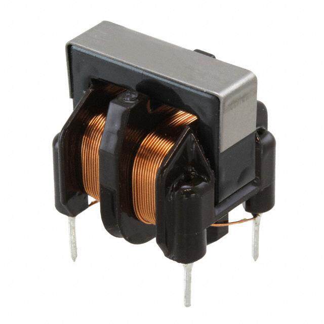
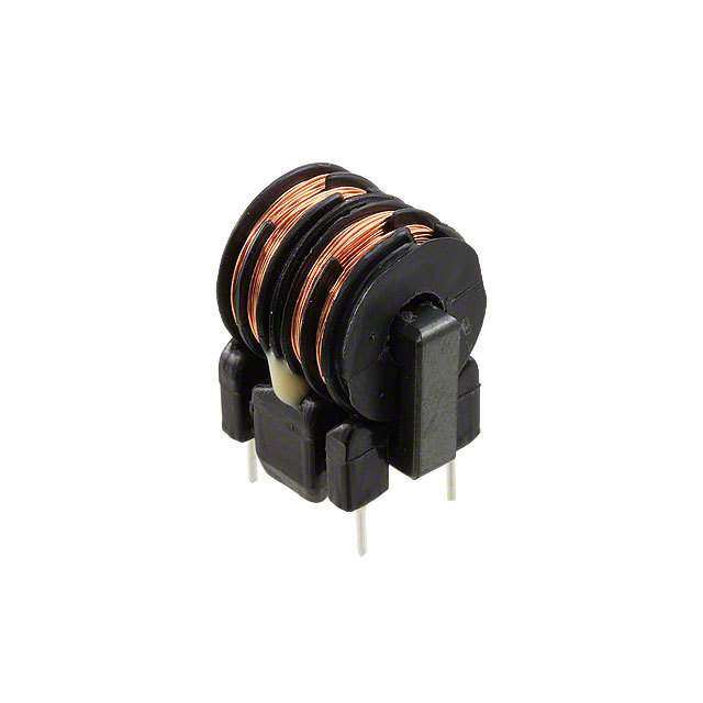
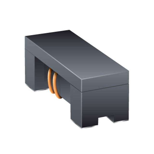
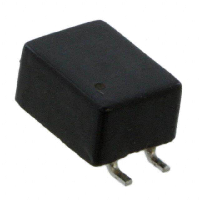
EEMMII FFiilltteerr SSeelleeccttiioonn bbyy CCiirrccuuiittss aanndd NNooiissee FFrreeqquueennccyy oChip Common Mode Choke Coil Circuit Type? High Speed Differential Signal Line DC Power Line Audio Line High Speed Signal Line Ultra High Speed Signal Line (USB/LVDS/IEEE1394/mipi etc.) (HDMI/DVI/Display Port etc.) DLW5AH p177 DLM11S p185 DLP0QSA p186 DLM11G p184 2014(5036)/0.2A/Imp.4000Ω 0504(1210)/Imp.45-90Ω 025020(0605)/Imp.7-35Ω 0504(1210)/Imp.600Ω DLW5AT p179 DLP0QSN p186 DLP0NSA p187 DLW5AT p179 2014(5036)/1-6A/Imp.50-2700Ω 025020(0605)/Imp.60Ω 03025(0806)/Imp.7-15Ω 2014(5036)/1-6A/Imp.50-2700Ω DLW5BS p177 DLP0NSC/SN p187 DLP11SA p189 DLW5BT p179 2020(5050)/0.5-5A/Imp.190-3000Ω 03025(0806)/Imp.28-120Ω 0504(1210)/Imp.35-90Ω 2020(5050)/1.5-6A/Imp.100-1400Ω DLW5BT p179 DLP11SN p189 DLP11RB p189 2020(5050)/1.5-6A/Imp.100-1400Ω 0504(1210)/Imp.67-330Ω 0504(1210)/Imp.15-40Ω High Current Type Automotive Available DLP11RN p189 DLP11TB p189 PLT10HH p202 0504(1210)/Imp.45Ω 0504(1210)/Imp.80Ω 12.9mmx6.6mm DLW21H p199 DLW21S_HQ p197 /6-18A/Imp.45-1000Ω 0805(2012)/Imp.67-180Ω 0805(2012)/Imp.67-120Ω DLW21S_S/X p197 Array Type 0805(2012)/Imp.67-500Ω DLP2ADA p194 DLP31S p192 0804(2010)/Imp.35-90Ω 1206(3216)/Imp.120-550Ω DLW31S p200 1206(3216)/Imp.90-2200Ω Automotive Available DLW43S p201 1812(4532) Array Type DLP1ND p193 05025(1506)/Imp.35-90Ω DLP2ADN p194 0804(2010)/Imp.67-280Ω DLP31D p196 1206(3216)/Imp.90-440Ω Guide of Digits in this Chart: ofor BLM03P ofor NFA18S 0201(0603)/0.75-0.9A/Imp.22-33Ω 0603(1608)/Cut off 50-480MHz Size Size Rated Current Impedance Size Size Cut-off Frequency (inch) (mm) (inch) (mm) ofor BNX022/023 ofor DLW5BS 10-15A/Range1MHz-2GHz 2020(5050)/0.5-5A/Imp.190-3000Ω Rated Current Effective Frequency Range Size Size Rated Current Impedance (inch) (mm) ofor NFR21GD 0805(2012)/22-100Ω/Cap.10-100pF Size Size Resistance Capacitance (inch) (mm) !Note(cid:129) Please read rating and !CAUTION (for storage, operating, rating, soldering, mounting and handling) in this catalog to prevent smoking and/or burning, etc. (cid:129) This catalog has only typical specifi cations. Therefore, please approve our product specifi cations or transact the approval sheet for product specifi cations before ordering. 9
PPrroodduucctt GGuuiiddee BL p Size Code Impedance (Ω) at 100MHz Effective Frequency Range Inductor Type Series (Applicable Frequency Ranges are only for reference.) in inch (in mm) 10 100 1000 10kHz100kHz 1MHz10MHz100MHz1GHz 10GHz p24 UniversalType[ PowerLines /SignalLines ] BBBLLLMMM010253AAAXXX pp3400 0001420000215 (((100064000532))) 111000 30 770080111222000 222040 660000 11000000 BLM03AG p32 0201 (0603) 80 10 70 120 240 600 1000 s ne BLM15AG p42 0402 (1005) 10 70 120 220 600 1000 Li nal BLM18A p56 0603 (1608) 120150220330 476000 1000 g al Si BLM21A p68 0805 (2012) 120150220330 476000 1000 ner BLM18T p62 0603 (1608) 120 220 600 1000 e or G B(4 LcAirc2uAitsA array) p80 0804 (2010) 120 220 600 1000 ype F B(4 LcAirc3u1itAs array) p83 1206 (3216) 30 60 120 220 600 1000 T es es BLM02BX p26 01005 (0402) 150 n n e al Li al Li BLM03B p34 0201 (0603) 10 22 3347567580120 240 476000 Nois Sign Sign BLM15B p44 0402 (1005) 510 22 3347 75 120 222040 476000 10001800 and eed BLM18B p58 0603 (1608) 510 22 476075 121041050220330424076000 10010501080202002500 or General B For High Sp BBB((44 LLLccMAAiirrcc322uu1Aii1ttBssBB aarrrraayy)) ppp788003 010828000564 (((232020111260))) 510 22 47607755 11122200012500220222002033042444077766600000000075011100000010005010802020202520700 F For DigitalInterfaceLines BBLLMM1281RR pp6733 00680035 ((12600182)) 112200 222200 447766000000 11000000 BLM03PX* p28 0201 (0603) 33 (1.5A) 22 (1.8A) 80 (1A) BLM03PG p27 0201 (0603) 33 (0.75A) 22 (0.9A) BLM15P* p36 0402 (1005) 33 (3A)80 (1.5A/2.3A)180 (1.5A)220 (1.4A)470 (1A) 10 (1A) 30 (2.2A)60 (1.7A/2.5A)120 (1.3A/2A)330 (1.2A)600 (0.9A) Type BLM18P* p50 0603 (1608) 30 (313A ()36A0) (0.5A1)2108 (02 A(1).52A2)0 3(13.04 A(1).24A7)0 (1A) nes BLM21P* p66 0805 (2012) 22 (63A0) (4A6)0 (3.5A)120 (3A2)20 (323A0) (1.5A) er Li BLM31P* p75 1206 (3216) 33 5(60A (3).5A) 120 (3.5A) 390 (2A6)00 (1.5A) Pow BLM41P* p77 1806 (4516) 607 5(6 (A3.)51A8)0 (3.5A) 470 (2A)1000 (1.5A) BLM18K* p52 0603 (1608) 30 (5A) 70 (3.5A) 220 (2.2A)470 (1.5A) (Low DC Resistance Type) 26 (6A) 100 (3A)120 (3A)330 (1.7A) 600 (1.3A) B(LoLwM DC1 R8esSis*tance Typpe5)4 0603 (1608) 26 (6A) 70 (4A)120 (3A22)0 (323.50A ()1.5A) p79 BLE32P 1210 (3225) 30 Universal Type[ Power Lines /Signal Lines ] BBBBLLLLMMMM11018538EEEHG**E** pppp89997062 0000642600003213 ((((1101606600008538)))) 25 (0.6A)50 (0.4A10)01 (1222A00) ((122.A252)0A 2()203A 3(/001 A.(70)A.536)A90)00 4( 70(00.5 .(A80)A.15)A6010)0050 0( (000. 5.(6A0A).5)A) BLM03HG p85 0201 (0603) 1000 e 600 1200 s oi BLM03HD p85 0201 (0603) 600 N 330 470 1000 d p85 n BLM03HB 0201 (0603) 190 a For GHz B al Lines Type BBBLLLMMM111555HHHDGB ppp888888 000444000222 (((111000000555))) 120 220 660000 110000001800 gn BLM18HG p92 0603 (1608) 600 Si 470 1000 BLM18HD p92 0603 (1608) 600 470 1000 p92 BLM18HB 0603 (1608) 120 220330 BLM18HK p92 0603 (1608) 600 330 470 1000 For High-GHzBand Noise Signal LinesType BBBLLLMMM111855GGGGA ppp999118 000644000322 (((111600000855))) 75 220 447700 * The derating of rated current is required for some items according to the operating temperature on each product page. !Note(cid:129) Please read rating and !CAUTION (for storage, operating, rating, soldering, mounting and handling) in this catalog to prevent smoking and/or burning, etc. (cid:129) This catalog has only typical specifi cations. Therefore, please approve our product specifi cations or transact the approval sheet for product specifi cations before ordering. 10
PPrroodduucctt GGuuiiddee NF p Size Code Capacitance (F) Effective Frequency Range Capacitor Type Series (Applicable Frequency Ranges are only for reference.) in inch (in mm) 10p 100p 1000p 10000p 0.1μ 1μ 10μ 10kHz100kHz 1MHz10MHz100MHz1GHz 10GHz NFM15CC p134 0402 (1005) 2200 22000 pe NFM18CC p135 0603 (1608) 470 2200 y 2247100220 1000 22000 T es NFM21CC p136 0805 (2012) 224710022047010002200 22000 n al Li NFM3DCC p137 1205 (3212) 224710022047010002200 22000 Sign NFM41CC p138 1806 (4516) 224710022047010002200 22000 NFA31CC p139 470 2200 (4 circuits array) 1206 (3216) 2247100220 1000 22000 NFM15PC p123 0402 (1005) 47000 0.22 1.0 0.1 0.47 4.3 NFM18PS p125 0603 (1608) 1.0 0.47 NFM18PC p126 0603 (1608) 0.22 1.0 e 0.1 0.47 2.2 p Ty NFM21PS p128 0805 (2012) 10 s ne NFM21PC p129 0805 (2012) 0.22 1.0 4.7 Li 0.1 0.47 2.2 er NFM3DPC* p130 1205 (3212) 22000 w Po NFM31PC p131 1206 (3216) 27 NFM31KC* p132 1206 (3216) 1000022000 15000 0.1 NFM41PC p133 1806 (4516) 0.2 1.5 UniversalType[ PowerLines /SignalLines ] NNFFEE3611PPTT pp112212 12270066 ((36281166)) 223347611800001820230640760810010502020040700 NF p Size Code Cut-off Frequency (MHz) Effective Frequency Range LC(RC) Combined Type Series (Applicable Frequency Ranges are only for reference.) in inch (in mm) 10 100 500 10kHz100kHz 1MHz10MHz100MHz1GHz 10GHz NFL15ST p140 0402 (1005) 150 200 300 500 NFL18ST p141 0603 (1608) 50 70 100 200 300 500 NFL18SP p143 0603 (1608) 150 200 300 500 ype NFL21SP p144 0805 (2012) 10 20 50 70 100 150 200 300 400500 es T N(4 FcAirc1u8itSs Larray)p145 0603 (1608) 50 130 180202020 300345000480 n Li NFA18SD p147 0603 (1608) 200 al (4 circuits array) 180 n NFA21SL p148 280310 Sig (4 circuits array) 0805 (2012) 50 80 200 300330 NFW31SP p150 1206 (3216) 400 10 20 50 100 150 200 300 500 NFR21GD p152 0805 (2012) NFA31GD p153 (4 circuits array) 1206 (3216) * The derating of rated current is required for some items according to the operating temperature on each product page. !Note(cid:129) Please read rating and !CAUTION (for storage, operating, rating, soldering, mounting and handling) in this catalog to prevent smoking and/or burning, etc. (cid:129) This catalog has only typical specifi cations. Therefore, please approve our product specifi cations or transact the approval sheet for product specifi cations before ordering. 11
PPrroodduucctt GGuuiiddee DL p Size Code Common Mode Impedance (Ω) at 100MHz Effective Frequency Range Common Mode Choke Coils Series (Applicable Frequency Ranges are only for reference.) in inch (in mm) 100 500 1000 100kHz 1MHz 10MHz 100MHz 1GHz 10GHz o p184 Audines DLM11G 0504 (1210) 600 or Li F DLM11S p185 0504 (1210) 45 90 DLP0QSN p186 025020 (0605) 60 DLP0QSA p186 025020 (0605) 15 7 35 DLP0NSC p187 03025 (0806) 28 DLP0NSN p187 03025 (0806) 35 90 67 120 DLP0NSA p187 03025 (0806) 15 7 es DLP11SN p189 0504 (1210) 6790 120160 200240280330 n Signal Lines Type h Speed Signal Li DDDDLLLLPPPP11111111SRRTBANB pppp111189999001 0000555500004444 ((((1111222211110000)))) 15344505687090 g Hi DLP31S p192 1206 (3216) 120 220 550 a Ultr D(2 LcPirc1uNitsD aNrray)p193 05025 (1506) 356790 or DLP2ADA p194 35 90 F (2 circuits array) 0804 (2010) 67 DLP2ADN p194 90 240 (2 circuits array) 0804 (2010) 67 120160 200 280 DLP31DN p196 (2 circuits array) 1206 (3216) 90 130 200 320 440 DLW21S p197 0805 (2012) 90 490 67 120 180 260 370 500 DLW21H p199 0805 (2012) 90 67 120 180 p200 DLW31SN 1206 (3216) 90 160 260 600 1000 2200 p201 DLW43SH 1812 (4532) UniversalType[ PowerLines /SignalLines ] DDLLWW55AAHT* / /DDLLWW55BBppS11T77**79 ((2525000013134646)) ((2525000025250000)) 50 101010150 190 232050 333500400550000600 88050011001001000011450000237400000000 PL p Large Current Common Mode Choke Coil Series Size Code Common Mode Impedance (Ω) at 10MHz (ApplicaEbflef eFcretqiuveen cFy rReaqnguees narce yo nRly afonr greeference.) for Automotive Available in inch (in mm) 100 500 1000 100kHz 1MHz 10MHz 100MHz 1GHz 10GHz LargeCurrentTypefor Auto-motiveAvailable PLT10HH* p202 – 45 100 400500 9010000 BNX Effective Frequency Range Block EMIFILr Series Height Rated Voltage Rated Current (Applicable Frequency Ranges are only for reference.) (mm) (Vdc) (A) 10kHz100kHz 1MHz10MHz100MHz1GHz 10GHz BNX022* p221 3.1 50 10 ype BNX023* p221 3.1 100 15 T e MD BNX024* p221 3.5 50 15 p S Ty BNX025* p221 3.5 25 15 s ne BNX002 p223 13 max. 50 10 Li wer pe BNX003 p223 13 max. 150 10 Po d Ty BNX005 p223 13.5 max. 50 15 a Le BNX012* p224 8.5 max. 50 15 BNX016* p224 8.5 max. 25 15 * The derating of rated current is required for some items according to the operating temperature on each product page. !Note(cid:129) Please read rating and !CAUTION (for storage, operating, rating, soldering, mounting and handling) in this catalog to prevent smoking and/or burning, etc. (cid:129) This catalog has only typical specifi cations. Therefore, please approve our product specifi cations or transact the approval sheet for product specifi cations before ordering. 12
BL dd aa p BeBe e e rritrrit ee FF p p hihi CC Chip Ferrite Bead Series Introduction 14 Part Numbering 16 r Series Line Up 18 FIL MI Product Detail 24 E p !Caution/Notice 99 Chi Soldering and Mounting 100 Packaging 104 Design Kits 105 oil C e k o h C e d o M n o m m o C p hi C r L FI MI E e p y T k c o Bl r e b r o s b A e v a w o r c Mi !Note(cid:129) Please read rating and !CAUTION (for storage, operating, rating, soldering, mounting and handling) in this catalog to prevent smoking and/or burning, etc. (cid:129) This catalog has only typical specifi cations. Therefore, please approve our product specifi cations or transact the approval sheet for product specifi cations before ordering.
BL p Series Introduction (cid:115) Example of Chip Ferrite Bead BLM Series Structure Inner Electrode Outer Electrode dd aa BeBe Ferrite Sheet e e rritrrit Through Hole ee FF p p hihi CC Cross Section r L FI MI E p (cid:115) hi Line Up Classification of C Chip Ferrite Bead Meets High-GHz 1600 Band Noise 1400 1200 Ω) Coil nce (1000 ke eda 800 o p Ch High-GHz Band BLM_G Series Im 600 e d High 400 o M (cid:115)(cid:39)(cid:33)(cid:0)(cid:8)(cid:70)(cid:79)(cid:82)(cid:0)(cid:72)(cid:73)(cid:71)(cid:72)(cid:0)(cid:83)(cid:80)(cid:69)(cid:69)(cid:68)(cid:0)(cid:83)(cid:73)(cid:71)(cid:78)(cid:65)(cid:76)(cid:0)(cid:76)(cid:73)(cid:78)(cid:69)(cid:83)(cid:9) n (cid:115)(cid:39)(cid:39)(cid:0)(cid:8)(cid:70)(cid:79)(cid:82)(cid:0)(cid:71)(cid:69)(cid:78)(cid:69)(cid:82)(cid:65)(cid:76)(cid:0)(cid:83)(cid:73)(cid:71)(cid:78)(cid:65)(cid:76)(cid:0)(cid:76)(cid:73)(cid:78)(cid:69)(cid:83)(cid:9) 200 o m 0 m 1 10 100 1000 10000 Co Frequency (MHz) p hi C BLM_H Series BLM_E Series GHz Band (cid:115)(cid:40)(cid:34)(cid:15)(cid:40)(cid:36)(cid:15)(cid:40)(cid:37)(cid:0)(cid:8)(cid:70)(cid:79)(cid:82)(cid:0)(cid:72)(cid:73)(cid:71)(cid:72)(cid:0)(cid:83)(cid:80)(cid:69)(cid:69)(cid:68)(cid:0)(cid:83)(cid:73)(cid:71)(cid:78)(cid:65)(cid:76)(cid:0)(cid:76)(cid:73)(cid:78)(cid:69)(cid:83)(cid:9) (cid:115)(cid:37)(cid:39)(cid:0)(cid:8)(cid:70)(cid:79)(cid:82)(cid:0)(cid:71)(cid:69)(cid:78)(cid:69)(cid:82)(cid:65)(cid:76)(cid:0)(cid:83)(cid:73)(cid:71)(cid:78)(cid:65)(cid:76)(cid:0)(cid:76)(cid:73)(cid:78)(cid:69)(cid:83)(cid:9) r Noise (cid:115)(cid:40)(cid:39)(cid:15)(cid:40)(cid:43)(cid:0)(cid:8)(cid:70)(cid:79)(cid:82)(cid:0)(cid:71)(cid:69)(cid:78)(cid:69)(cid:82)(cid:65)(cid:76)(cid:0)(cid:83)(cid:73)(cid:71)(cid:78)(cid:65)(cid:76)(cid:0)(cid:76)(cid:73)(cid:78)(cid:69)(cid:83)(cid:9) (cid:115)(cid:37)(cid:34)(cid:0)(cid:8)(cid:70)(cid:79)(cid:82)(cid:0)(cid:71)(cid:69)(cid:78)(cid:69)(cid:82)(cid:65)(cid:76)(cid:0)(cid:83)(cid:73)(cid:71)(cid:78)(cid:65)(cid:76)(cid:0)(cid:76)(cid:73)(cid:78)(cid:69)(cid:83)(cid:0)(cid:15)(cid:0)(cid:70)(cid:79)(cid:82)(cid:0)(cid:80)(cid:79)(cid:87)(cid:69)(cid:82)(cid:0)(cid:76)(cid:73)(cid:78)(cid:69)(cid:83)(cid:9) L FI Frequency Band MI E e p y T k c o Bl BLM standard line up BLE/BLM_P/BLM_K Series (for Power Lines) (cid:115)(cid:50)(cid:43)(cid:0)(cid:8)(cid:70)(cid:79)(cid:82)(cid:0)(cid:68)(cid:73)(cid:71)(cid:73)(cid:84)(cid:65)(cid:76)(cid:0)(cid:73)(cid:78)(cid:84)(cid:69)(cid:82)(cid:70)(cid:65)(cid:67)(cid:69)(cid:83)(cid:9) (cid:115)(cid:33)(cid:39)(cid:0)(cid:8)(cid:70)(cid:79)(cid:82)(cid:0)(cid:71)(cid:69)(cid:78)(cid:69)(cid:82)(cid:65)(cid:76)(cid:0)(cid:83)(cid:73)(cid:71)(cid:78)(cid:65)(cid:76)(cid:0)(cid:76)(cid:73)(cid:78)(cid:69)(cid:83)(cid:9) (cid:115)(cid:34)(cid:44)(cid:45)(cid:63)(cid:48)(cid:15)(cid:43)(cid:0)(cid:8)(cid:44)(cid:65)(cid:82)(cid:71)(cid:69)(cid:0)(cid:67)(cid:85)(cid:82)(cid:82)(cid:69)(cid:78)(cid:84)(cid:0)(cid:65)(cid:86)(cid:65)(cid:73)(cid:76)(cid:65)(cid:66)(cid:76)(cid:69)(cid:0)(cid:85)(cid:80)(cid:0)(cid:84)(cid:79)(cid:0)(cid:22)(cid:33)(cid:9) (cid:115)(cid:34)p(cid:0)(cid:8)(cid:70)(cid:79)(cid:82)(cid:0)(cid:72)(cid:73)(cid:71)(cid:72)(cid:0)(cid:83)(cid:80)(cid:69)(cid:69)(cid:68)(cid:0)(cid:83)(cid:73)(cid:71)(cid:78)(cid:65)(cid:76)(cid:0)(cid:76)(cid:73)(cid:78)(cid:69)(cid:83)(cid:9) (cid:115)(cid:34)(cid:44)(cid:37)(cid:0)(cid:8)(cid:44)(cid:65)(cid:82)(cid:71)(cid:69)(cid:0)(cid:67)(cid:85)(cid:82)(cid:82)(cid:69)(cid:78)(cid:84)(cid:0)(cid:65)(cid:86)(cid:65)(cid:73)(cid:76)(cid:65)(cid:66)(cid:76)(cid:69)(cid:0)(cid:85)(cid:80)(cid:0)(cid:84)(cid:79)(cid:0)(cid:17)(cid:16)(cid:33)(cid:9) Low (cid:115)(cid:33)(cid:56) (cid:8)(cid:70)(cid:79)(cid:82)(cid:0)(cid:71)(cid:69)(cid:78)(cid:69)(cid:82)(cid:65)(cid:76)(cid:0)(cid:83)(cid:73)(cid:71)(cid:78)(cid:65)(cid:76)(cid:0)(cid:76)(cid:73)(cid:78)(cid:69)(cid:83)(cid:0)(cid:15)(cid:0)(cid:80)(cid:79)(cid:87)(cid:69)(cid:82)(cid:0)(cid:76)(cid:73)(cid:78)(cid:69)(cid:83)(cid:9) r e b r o bs Small Rated Current Large A e (Less than 1A) (1A and more) v a w o r c Mi !Note(cid:129) Please read rating and !CAUTION (for storage, operating, rating, soldering, mounting and handling) in this catalog to prevent smoking and/or burning, etc. (cid:129) This catalog has only typical specifi cations. Therefore, please approve our product specifi cations or transact the approval sheet for product specifi cations before ordering. 14
BLp Series Introduction (cid:115) Difference between BLM A type and B type (HG type vs HD/HB/HE type) A type: Impedance curve rises from low frequency range. Suppresses noise in a wide frequency range. B type: Impedance curve rises sharply. Less damage to signal waveforms. dd aa ee BB e e rritrrit cComparison of Impedance Curve cComparison of Resistance Element FeFe p p hihi CC 1200 1200 BLM18BD601SN1 BLM18BD601SN1 900 900 Ω) Ω) Z ( 600 BLM18AG601SN1 R ( 600 BLM18AG601SN1 300 300 0 0 1 10 100 1000 1 10 100 1000 r L Frequency (MHz) Frequency (MHz) MIFI E p hi C cComparison of Test Effect (25MHz) Test Circuit Waveform test point 29.7cm oil C 25MHz 1cm ke OSC Ferrite Bead ho m C 7c Pattern width 0.15cm de 74HC04 74HC04 Line impedance 127Ω 74HC00 Mo Both side glass epoxy PCB(ε4.7) n o All of back side is GND PCB thickness=0.6mm m m o C p hi C BLM_B Series has less damage to high speed signal waveform. Small Distortion No filter BLM18AG601SN1 BLM18BD601SN1 r L Waveform FI MI E e p y T k c o Bl Spectrum r e b r o s b A e v a Spectrum has been reduced from low Noise frequency has been reduced without w frequency range. reducing signals of low frequency. o r c Mi !Note(cid:129) Please read rating and !CAUTION (for storage, operating, rating, soldering, mounting and handling) in this catalog to prevent smoking and/or burning, etc. (cid:129) This catalog has only typical specifi cations. Therefore, please approve our product specifi cations or transact the approval sheet for product specifi cations before ordering. 15
BL p Part Numbering Chip Ferrite Bead (Part Number) BL M 18 AG 102 S N 1 D q w e r t y u i o qProduct ID tImpedance Product ID Expressed by three figures. The unit is in ohm (Ω) at 100MHz. The first and second figures are significant digits, and the third figure dd BL Chip Ferrite Beads aa expresses the number of zeros that follow the two figures. ee BB rrite rrite wType yElectrode FeFe Code Type Expressed by a letter. p p hihi A Array Type Ex.) Code Electrode CC E DC Bias Characteristics Improved Type S/T Sn Plating M Ferrite Bead Single Type A Au Plating eDimensions (LgW) uCategory Code Dimensions (LgW) EIA Code Category 02 0.4g0.2mm 01005 N Standard Type r 03 0.6g0.3mm 0201 L FI 15 1.0g0.5mm 0402 iNumber of Circuits MI E 18 1.6g0.8mm 0603 Code Number of Circuits p hi 2A 2.0g1.0mm 0804 1 1 Circuit C 21 2.0g1.25mm 0805 4 4 Circuits 31 3.2g1.6mm 1206 32 3.2g2.5mm 1210 41 4.5g1.6mm 1806 oil e C rCharacteristics/Applications k ho Code *1 Characteristics/Applications Series C e AG BLM03/15/18/21, BLA2A/31 d Mo AX For General Use BLM02/03/15 on TG BLM18 m m BA BLM15/18 o C BB BLM03/15/18/21, BLA2A p hi BC For High-speed Signal Lines BLM03/15 C BD BLM03/15/18/21, BLA2A/31 BX BLM02/15 PD BLM15 PG BLM03/15/18/21/31/41 rL For Power Lines FI PN BLE32 MI E PX BLM03/15 e yp KG T For Power Lines (Low DC Resistance Type) BLM18 k SG c o Bl RK For Digital Interface BLM18/21 HG For GHz Band General Use BLM03/15/18 EB For GHz Band High-speed Signal Lines (Low Direct Current Type) BLM03 EG For GHz Band General Use (Low DC Resistance Type) BLM15/18 HB BLM03/15/18 HD For GHz Band High-speed Signal Lines BLM03/15/18 r e b HE BLM18 r o s HK For GHz Band Digital Interface BLM18 b A e GA For High-GHz Band High-speed Signal Lines BLM15 v wa GG For High-GHz Band General Use BLM15/18 ro *1 Frequency characteristics vary with each code. c Mi Continued on the following page. !Note(cid:129) Please read rating and !CAUTION (for storage, operating, rating, soldering, mounting and handling) in this catalog to prevent smoking and/or burning, etc. (cid:129) This catalog has only typical specifi cations. Therefore, please approve our product specifi cations or transact the approval sheet for product specifi cations before ordering. 16
BLp Chip Ferrite Bead Part Numbering oPackaging Code Packaging Series K Embossed Taping (ø330mm Reel) BLE, BLM21 *1/31/41 L Embossed Taping (ø180mm Reel) B Bulk All Series J Paper Taping (ø330mm Reel) BLM03/15/18 *3/21 *2, BLA2A/31 dd aa ee D Paper Taping (ø180mm Reel) BLM02/03/15/18/21 *2, BLA2A/31 BB e e *1 BLM21BD222SN1/BLM21BD272SN1 only. rritrrit *2 Except for BLM21BD222SN1/BLM21BD272SN1 FeFe *3 Except for BLM18T p p hihi CC r L FI MI E p hi C oil C e k o h C e d o M n o m m o C p hi C r L FI MI E e p y T k c o Bl r e b r o s b A e v a w o r c Mi !Note(cid:129) Please read rating and !CAUTION (for storage, operating, rating, soldering, mounting and handling) in this catalog to prevent smoking and/or burning, etc. (cid:129) This catalog has only typical specifi cations. Therefore, please approve our product specifi cations or transact the approval sheet for product specifi cations before ordering. 17
BL p Chip Ferrite Bead Series Line Up (iinCnS oiimnzdcemeh)T(hmickmnes)s Type Part Number at 100MHz/2Im0°pCedanact e1GHz/20°C CRuartreednt 0.2 p24 BLM02AX100SN1 10ohm±5ohm - 750mA Universal Type 01005 0.2 BLM02AX700SN1 70ohm±25% - 300mA [Power lines/Signal lines] (0402) 0.2 BLM02AX121SN1 120ohm±25% - 250mA 0.2 For High Speed Signal Lines p26 BLM02BX151SN1 150ohm±25% - 200mA 0.3 p32 BLM03AG100SN1 10ohm(Typ.) - 500mA dd aa 0.3 BLM03AG700SN1 70ohm(Typ.) - 200mA ee e Be B 0.3 BLM03AG800SN1 80ohm±25% - 200mA rritrrit 0.3 For General Signal Lines BLM03AG121SN1 120ohm±25% - 200mA ee FF 0.3 BLM03AG241SN1 240ohm±25% - 200mA p p hihi 0.3 BLM03AG601SN1 600ohm±25% - 100mA CC 0.3 BLM03AG102SN1 1000ohm±25% - 100mA 0.3 p30 BLM03AX100SN1 10ohm(Typ.) - 1000mA 0.3 BLM03AX800SN1 80ohm±25% - 500mA 0.3 Universal Type BLM03AX121SN1 120ohm±25% - 450mA 0.3 [Power lines/Signal lines] BLM03AX241SN1 240ohm±25% - 350mA 0.3 BLM03AX601SN1 600ohm±25% - 250mA 0.3 BLM03AX102SN1 1000ohm±25% - 200mA 0.3 p34 BLM03BD750SN1 75ohm±25% - 300mA r L 0.3 BLM03BD121SN1 120ohm±25% - 250mA FI MI 0.3 BLM03BD241SN1 240ohm±25% - 200mA p E 0.3 BLM03BD471SN1 470ohm±25% - 215mA hi 0.3 BLM03BD601SN1 600ohm±25% - 200mA C 0.3 BLM03BB100SN1 10ohm±25% - 300mA For High Speed Signal Lines 0.3 BLM03BB220SN1 22ohm±25% - 200mA 0201 (Sharp Impedance Curve) 0.3 BLM03BB470SN1 47ohm±25% - 200mA (0603) 0.3 BLM03BB750SN1 75ohm±25% - 200mA 0.3 BLM03BB121SN1 120ohm±25% - 100mA oil 0.3 BLM03BC330SN1 33ohm±25% - 150mA e C 0.3 BLM03BC560SN1 56ohm±25% - 100mA ok 0.3 BLM03BC800SN1 80ohm±25% - 100mA h C 0.3 p27 BLM03PG220SN1 22ohm±25% - 900mA e d 0.3 BLM03PG330SN1 33ohm±25% - 750mA o M 0.3 For Power Lines p28 BLM03PX220SN1 22ohm±25% - 1800mA on 0.3 BLM03PX330SN1 33ohm±25% - 1500mA m m 0.3 BLM03PX800SN1 80ohm±25% - 1000mA Co 0.3 p85 BLM03HG601SN1 600ohm±25% 1000ohm±40% 150mA hip 0.3 SFoigrn Gale Lnienreasl BLM03HG102SN1 1000ohm±25% 1800ohm±40% 125mA C 0.3 BLM03HG122SN1 1200ohm±25% 2000ohm±40% 100mA 0.3 Universal Type p87 BLM03EB250SN1 25ohm±25% 105ohm±40% 600mA 0.3 For GHz [Power lines/Signal lines] BLM03EB500SN1 50ohm±25% 255ohm±40% 400mA 0.3 Band Noise p85 BLM03HD331SN1 330ohm±25% 750ohm±40% 200mA 0.3 BLM03HD471SN1 470ohm±25% 1000ohm±40% 175mA r For High Speed FIL 0.3 Signal Lines BLM03HD601SN1 600ohm±25% 1500ohm±40% 150mA MI 0.3 BLM03HD102SN1 1000ohm±25% 2300ohm±40% 120mA E e 0.3 BLM03HB191SN1 190ohm±25% 1150ohm±40% 150mA p y 0.5 p42 BLM15AG100SN1 10ohm(Typ.) -- 1000mA T k 0.5 BLM15AG700SN1 70ohm(Typ.) - 600mA c o Bl 0.5 For General Signal Lines BLM15AG121SN1 120ohm±25% - 550mA 0.5 BLM15AG221SN1 220ohm±25% - 450mA 0.5 BLM15AG601SN1 600ohm±25% - 300mA 0.5 BLM15AG102SN1 1000ohm±25% - 300mA 0402 0.5 p40 BLM15AX100SN1 10ohm±5ohm - 1740mA (1005) 0.5 BLM15AX300SN1 30ohm±25% - 1100mA 0.5 BLM15AX700SN1 70ohm±25% - 780mA r Universal Type rbe 0.5 [Power lines/Signal lines] BLM15AX121SN1 120ohm±25% - 700mA o 0.5 BLM15AX221SN1 220ohm±25% - 600mA s b A 0.5 BLM15AX601SN1 600ohm±25% - 500mA ve 0.5 BLM15AX102SN1 1000ohm±25% - 350mA a w Continued on the following page. o r c Mi !Note(cid:129) Please read rating and !CAUTION (for storage, operating, rating, soldering, mounting and handling) in this catalog to prevent smoking and/or burning, etc. (cid:129) This catalog has only typical specifi cations. Therefore, please approve our product specifi cations or transact the approval sheet for product specifi cations before ordering. 18
BLp Chip Ferrite Bead Series Line Up (iinCnS oiimnzdcemeh)T(hmickmnes)s Type Part Number at 100MHz/2Im0°pCedanact e1GHz/20°C CRuartreednt 0.5 p44 BLM15BX750SN1 75ohm±25% - 600mA 0.5 BLM15BX121SN1 120ohm±25% - 600mA 0.5 BLM15BX221SN1 220ohm±25% - 450mA 0.5 BLM15BX471SN1 470ohm±25% - 350mA 0.5 BLM15BX601SN1 600ohm±25% - 350mA dd 0.5 BLM15BX102SN1 1000ohm±25% - 300mA aa ee 0.5 BLM15BX182SN1 1800ohm±25% - 250mA e Be B 0.5 p46 BLM15BD750SN1 75ohm±25% - 300mA rritrrit ee 0.5 BLM15BD121SN1 120ohm±25% - 300mA FF p p 0.5 BLM15BD221SN1 220ohm±25% - 300mA hihi CC 0.5 BLM15BD471SN1 470ohm±25% - 200mA 0.5 BLM15BD601SN1 600ohm±25% - 200mA 0.5 BLM15BD102SN1 1000ohm±25% - 200mA 0.5 BLM15BD182SN1 1800ohm±25% - 100mA For High Speed Signal Lines 0.5 BLM15BB050SN1 5ohm±25% - 500mA (Sharp Impedance Curve) 0.5 BLM15BB100SN1 10ohm±25% - 300mA 0.5 BLM15BB220SN1 22ohm±25% - 300mA 0.5 BLM15BB470SN1 47ohm±25% - 300mA r 0.5 BLM15BB750SN1 75ohm±25% - 300mA L FI 0.5 BLM15BB121SN1 120ohm±25% - 300mA MI 0.5 BLM15BB221SN1 220ohm±25% - 200mA p E 0.5 BLM15BC121SN1 120ohm±25% - 350mA hi C 0.5 BLM15BC241SN1 240ohm±25% - 250mA 0.5 BLM15BA050SN1 5ohm±25% - 300mA 0.5 BLM15BA100SN1 10ohm±25% - 300mA 0.5 BLM15BA220SN1 22ohm±25% - 300mA 0.5 BLM15BA330SN1 33ohm±25% - 300mA 0402 (1005) 0.5 BLM15BA470SN1 47ohm±25% - 200mA oil 0.5 BLM15BA750SN1 75ohm±25% - 200mA e C 0.5 p36 BLM15PX330SN1 33ohm±25% - 3000mA ok h 0.5 BLM15PX600SN1 60ohm±25% - 2500mA C e 0.5 BLM15PX800SN1 80ohm±25% - 2300mA d o 0.5 BLM15PX121SN1 120ohm±25% - 2000mA M 0.5 BLM15PX181SN1 180ohm±25% - 1500mA on m 0.5 BLM15PX221SN1 220ohm±25% - 1400mA m 0.5 BLM15PX331SN1 330ohm±25% - 1200mA Co 0.5 For Power Lines BLM15PX471SN1 470ohm±25% - 1000mA hip 0.5 BLM15PX601SN1 600ohm±25% - 900mA C 0.5 p38 BLM15PG100SN1 10ohm(Typ.) - 1000mA 0.5 BLM15PD300SN1 30ohm±25% - 2200mA 0.5 BLM15PD600SN1 60ohm±25% - 1700mA 0.5 BLM15PD800SN1 80ohm±25% - 1500mA r 0.5 BLM15PD121SN1 120ohm±25% - 1300mA FIL 0.5 p88 BLM15HG601SN1 600ohm±25% 1000ohm±40% 300mA MI 0.5 For General Signal Lines BLM15HG102SN1 1000ohm±25% 1400ohm±40% 250mA e E p 0.5 p88 BLM15HD601SN1 600ohm±25% 1400ohm±40% 300mA y T 0.5 For High Speed BLM15HD102SN1 1000ohm±25% 2000ohm±40% 250mA ck o 0.5 For GHz Signal Lines BLM15HD182SN1 1800ohm±25% 2700ohm±40% 200mA Bl 0.5 Band Noise (Sharp Impedance Curve) BLM15HB121SN1 120ohm±25% 500ohm±40% 300mA 0.5 BLM15HB221SN1 220ohm±25% 900ohm±40% 250mA 0.5 Universal Type p90 BLM15EG121SN1 120ohm±25% 145ohm(Typ.) 1500mA 0.5 [Power Lines/Signal Lines] BLM15EG221SN1 220ohm±25% 270ohm(Typ.) 700mA 0.5 p91 BLM15GG221SN1 220ohm±25% 600ohm±40% 300mA 0.5 For High-GHz For General Signal Lines BLM15GG471SN1 470ohm±25% 1200ohm±40% 200mA Band Noise r 0.5 For High Speed Signal Linesp91 BLM15GA750SN1 75ohm±25% 1000ohm±40% 200mA e b r Continued on the following page. o s b A e v a w o r c Mi !Note(cid:129) Please read rating and !CAUTION (for storage, operating, rating, soldering, mounting and handling) in this catalog to prevent smoking and/or burning, etc. (cid:129) This catalog has only typical specifi cations. Therefore, please approve our product specifi cations or transact the approval sheet for product specifi cations before ordering. 19
BLp Chip Ferrite Bead Series Line Up (iinCnS oiimnzdcemeh)T(hmickmnes)s Type Part Number at 100MHz/2Im0°pCedanact e1GHz/20°C CRuartreednt 0.8 p56 BLM18AG121SN1 120ohm±25% - 500mA 0.8 BLM18AG151SN1 150ohm±25% - 500mA 0.8 BLM18AG221SN1 220ohm±25% - 500mA 0.8 BLM18AG331SN1 330ohm±25% - 500mA 0.8 BLM18AG471SN1 470ohm±25% - 500mA dd aa 0.8 For General Signal Lines BLM18AG601SN1 600ohm±25% - 500mA ee e Be B 0.8 BLM18AG102SN1 1000ohm±25% - 400mA rritrrit 0.6 p62 BLM18TG121TN1 120ohm±25% - 200mA ee FF 0.6 BLM18TG221TN1 220ohm±25% - 200mA p p hihi 0.6 BLM18TG601TN1 600ohm±25% - 200mA CC 0.6 BLM18TG102TN1 1000ohm±25% - 100mA 0.8 p58 BLM18BD470SN1 47ohm±25% - 500mA 0.8 BLM18BD121SN1 120ohm±25% - 200mA 0.8 BLM18BD151SN1 150ohm±25% - 200mA 0.8 BLM18BD221SN1 220ohm±25% - 200mA 0.8 BLM18BD331SN1 330ohm±25% - 200mA 0.8 BLM18BD421SN1 420ohm±25% - 200mA 0.8 BLM18BD471SN1 470ohm±25% - 200mA r L 0.8 BLM18BD601SN1 600ohm±25% - 200mA FI MI 0.8 BLM18BD102SN1 1000ohm±25% - 100mA p E 0.8 BLM18BD152SN1 1500ohm±25% - 50mA hi 0.8 BLM18BD182SN1 1800ohm±25% - 50mA C 0.8 BLM18BD222SN1 2200ohm±25% - 50mA 0603 0.8 BLM18BD252SN1 2500ohm±25% - 50mA (1608) 0.8 BLM18BB050SN1 5ohm±25% - 700mA 0.8 BLM18BB100SN1 10ohm±25% - 700mA For High Speed Signal Lines 0.8 BLM18BB220SN1 22ohm±25% - 600mA (Sharp Impedance Curve) oil 0.8 BLM18BB470SN1 47ohm±25% - 550mA e C 0.8 BLM18BB600SN1 60ohm±25% - 550mA ok 0.8 BLM18BB750SN1 75ohm±25% - 500mA h C 0.8 BLM18BB121SN1 120ohm±25% - 500mA e d 0.8 BLM18BB141SN1 140ohm±25% - 450mA o M 0.8 BLM18BB151SN1 150ohm±25% - 450mA on 0.8 BLM18BB221SN1 220ohm±25% - 450mA m m 0.8 BLM18BB331SN1 330ohm±25% - 400mA Co 0.8 BLM18BB471SN1 470ohm±25% - 300mA hip 0.8 BLM18BA050SN1 5ohm±25% - 500mA C 0.8 BLM18BA100SN1 10ohm±25% - 500mA 0.8 BLM18BA220SN1 22ohm±25% - 500mA 0.8 BLM18BA470SN1 47ohm±25% - 300mA 0.8 BLM18BA750SN1 75ohm±25% - 300mA 0.8 BLM18BA121SN1 120ohm±25% - 200mA r FIL 0.8 p63 BLM18RK121SN1 120ohm±25% - 200mA MI 0.8 BLM18RK221SN1 220ohm±25% - 200mA E e 0.8 For Digital Interface Lines BLM18RK471SN1 470ohm±25% - 200mA p y 0.8 BLM18RK601SN1 600ohm±25% - 200mA T k 0.8 BLM18RK102SN1 1000ohm±25% - 200mA c o Bl Continued on the following page. r e b r o s b A e v a w o r c Mi !Note(cid:129) Please read rating and !CAUTION (for storage, operating, rating, soldering, mounting and handling) in this catalog to prevent smoking and/or burning, etc. (cid:129) This catalog has only typical specifi cations. Therefore, please approve our product specifi cations or transact the approval sheet for product specifi cations before ordering. 20
BLp Chip Ferrite Bead Series Line Up (iinCnS oiimnzdcemeh)T(hmickmnes)s Type Part Number at 100MHz/2Im0°pCedanact e1GHz/20°C CRuartreednt 0.8 p50 BLM18PG300SN1 30ohm(Typ.) - 1000mA 0.8 BLM18PG330SN1 33ohm±25% - 3000mA 0.8 BLM18PG600SN1 60ohm(Typ.) - 500mA 0.8 BLM18PG121SN1 120ohm±25% - 2000mA Standard Type 0.8 BLM18PG181SN1 180ohm±25% - 1500mA dd 0.8 BLM18PG221SN1 220ohm±25% - 1400mA aa ee 0.8 BLM18PG331SN1 330ohm±25% - 1200mA e Be B 0.8 BLM18PG471SN1 470ohm±25% - 1000mA rritrrit ee 0.6 p52 BLM18KG260TN1 26ohm±25% - 6000mA FF p p 0.6 BLM18KG300TN1 30ohm±25% - 5000mA hihi CC 0.6 For Power BLM18KG700TN1 70ohm±25% - 3500mA 0.6 Lines BLM18KG101TN1 100ohm±25% - 3000mA 0.6 BLM18KG121TN1 120ohm±25% - 3000mA 0.8 BLM18KG221SN1 220ohm±25% - 2200mA 0.8 Low DC Resistance BLM18KG331SN1 330ohm±25% - 1700mA 0.8 Type BLM18KG471SN1 470ohm±25% - 1500mA 0.8 BLM18KG601SN1 600ohm±25% - 1300mA 0.5 p54 BLM18SG260TN1 26ohm±25% - 6000mA r 0.5 BLM18SG700TN1 70ohm±25% - 4000mA L FI 0.5 BLM18SG121TN1 120ohm±25% - 3000mA MI 0.5 BLM18SG221TN1 220ohm±25% - 2500mA p E 0.5 BLM18SG331TN1 330ohm±25% - 1500mA hi C 0.8 p92 BLM18HG471SN1 470ohm±25% 600ohm(Typ.) 200mA 0603 For General Signal 0.8 BLM18HG601SN1 600ohm±25% 700ohm(Typ.) 200mA (1608) Lines 0.8 BLM18HG102SN1 1000ohm±25% 1000ohm(Typ.) 100mA 0.8 p92 BLM18HE601SN1 600ohm±25% 600ohm(Typ.) 800mA 0.8 BLM18HE102SN1 1000ohm±25% 1000ohm(Typ.) 600mA 000...888 (SFhoSari rgHpn iIgamhl p LSeinpdeeasendce BBBLLLMMM111888HHHDDE146570211SSSNNN111 1465700000ooohhhmmm±±±222555%%% 111025000000ooohhhmmm(((TTTyyyppp...))) 115000000mmmAAA hoke Coil 0.8 BLM18HD102SN1 1000ohm±25% 1700ohm(Typ.) 50mA C Curve) e 0.8 BLM18HB121SN1 120ohm±25% 500ohm±40% 200mA d o 0.8 BLM18HB221SN1 220ohm±25% 1100ohm±40% 100mA M 0.8 For GHz BLM18HB331SN1 330ohm±25% 1600ohm±40% 50mA on m 0.8 Band Noise p92 BLM18HK331SN1 330ohm±25% 400ohm±40% 200mA m 0.8 For Digital Interface BLM18HK471SN1 470ohm±25% 600ohm±40% 200mA Co 0.8 Lines BLM18HK601SN1 600ohm±25% 700ohm±40% 100mA hip 0.8 BLM18HK102SN1 1000ohm±25% 1200ohm±40% 50mA C 0.5 p96 BLM18EG101TN1 100ohm±25% 140ohm(Typ.) 2000mA 0.8 BLM18EG121SN1 120ohm±25% 145ohm(Typ.) 2000mA 0.8 BLM18EG221SN1 220ohm±25% 260ohm(Typ.) 2000mA Universal Type 0.5 BLM18EG221TN1 220ohm±25% 300ohm(Typ.) 1000mA [Power lines/ r 0.5 Signal lines] BLM18EG331TN1 330ohm±25% 450ohm(Typ.) 500mA FIL 0.5 BLM18EG391TN1 390ohm±25% 520ohm(Typ.) 500mA MI E 0.8 BLM18EG471SN1 470ohm±25% 550ohm(Typ.) 500mA e p 0.8 BLM18EG601SN1 600ohm±25% 700ohm(Typ.) 500mA y T 0.8 For High-GHz Band Noise p98 BLM18GG471SN1 470ohm±25% 1800ohm±30% 200mA k c o 0.85 p68 BLM21AG121SN1 120ohm±25% - 800mA Bl 0.85 BLM21AG151SN1 150ohm±25% - 800mA 0.85 BLM21AG221SN1 220ohm±25% - 800mA 0805 0.85 For General Signal Lines BLM21AG331SN1 330ohm±25% - 700mA (2012) 0.85 BLM21AG471SN1 470ohm±25% - 700mA 0.85 BLM21AG601SN1 600ohm±25% - 600mA 0.85 BLM21AG102SN1 1000ohm±25% - 500mA r Continued on the following page. be r o s b A e v a w o r c Mi !Note(cid:129) Please read rating and !CAUTION (for storage, operating, rating, soldering, mounting and handling) in this catalog to prevent smoking and/or burning, etc. (cid:129) This catalog has only typical specifi cations. Therefore, please approve our product specifi cations or transact the approval sheet for product specifi cations before ordering. 21
BLp Chip Ferrite Bead Series Line Up (iinCnS oiimnzdcemeh)T(hmickmnes)s Type Part Number at 100MHz/2Im0°pCedanact e1GHz/20°C CRuartreednt 0.85 p70 BLM21BD121SN1 120ohm±25% - 200mA 0.85 BLM21BD151SN1 150ohm±25% - 200mA 0.85 BLM21BD221SN1 220ohm±25% - 200mA 0.85 BLM21BD331SN1 330ohm±25% - 200mA 0.85 BLM21BD421SN1 420ohm±25% - 200mA dd aa 0.85 BLM21BD471SN1 470ohm±25% - 200mA ee e Be B 0.85 BLM21BD601SN1 600ohm±25% - 200mA rritrrit 0.85 BLM21BD751SN1 750ohm±25% - 200mA ee FF 0.85 BLM21BD102SN1 1000ohm±25% - 200mA p p hihi 0.85 BLM21BD152SN1 1500ohm±25% - 200mA CC 0.85 BLM21BD182SN1 1800ohm±25% - 200mA For High Speed Signal Lines 0.85 BLM21BD222TN1 2200ohm±25% - 200mA (Sharp Impedance Curve) 1.25 BLM21BD222SN1 2250ohm(Typ.) - 200mA 1.25 BLM21BD272SN1 2700ohm±25% - 200mA 0.85 BLM21BB050SN1 5ohm±25% - 1000mA 0.85 BLM21BB600SN1 60ohm±25% - 800mA 0805 0.85 BLM21BB750SN1 75ohm±25% - 700mA (2012) 0.85 BLM21BB121SN1 120ohm±25% - 600mA r L 0.85 BLM21BB151SN1 150ohm±25% - 600mA FI MI 0.85 BLM21BB201SN1 200ohm±25% - 500mA p E 0.85 BLM21BB221SN1 220ohm±25% - 500mA hi 0.85 BLM21BB331SN1 330ohm±25% - 400mA C 0.85 BLM21BB471SN1 470ohm±25% - 400mA 0.85 p73 BLM21RK121SN1 120ohm±25% - 200mA 0.85 BLM21RK221SN1 220ohm±25% - 200mA 0.85 For Digital Interface Lines BLM21RK471SN1 470ohm±25% - 200mA 0.85 BLM21RK601SN1 600ohm±25% - 200mA oil 0.85 BLM21RK102SN1 1000ohm±25% - 200mA e C 0.85 p66 BLM21PG220SN1 22ohm±25% - 6000mA ok 0.85 BLM21PG300SN1 30ohm(Typ.) - 4000mA h C 0.85 BLM21PG600SN1 60ohm±25% - 3500mA e For Power Lines d 0.85 BLM21PG121SN1 120ohm±25% - 3000mA o M 0.85 BLM21PG221SN1 220ohm±25% - 2000mA on 0.85 BLM21PG331SN1 330ohm±25% - 1500mA m m 1.1 p75 BLM31PG330SN1 33ohm±25% - 6000mA Co 1.1 BLM31PG500SN1 50ohm(Typ.) - 3500mA hip (13220166) 1.1 For Power Lines BLM31PG121SN1 120ohm±25% - 3500mA C 1.1 BLM31PG391SN1 390ohm±25% - 2000mA 1.1 BLM31PG601SN1 600ohm±25% - 1500mA 1.6 p77 BLM41PG600SN1 60ohm(Typ.) - 6000mA 1.6 BLM41PG750SN1 75ohm(Typ.) - 3500mA 1806 1.6 For Power Lines BLM41PG181SN1 180ohm±25% - 3500mA r (4516) FIL 1.6 BLM41PG471SN1 470ohm±25% - 2000mA MI 1.6 BLM41PG102SN1 1000ohm±25% - 1500mA e E (13221205) 0.2 For Power Lines p79 BLE32PN300SN1 30ohm±10ohm - 10000mA p y 0.5 p80 BLA2AAG121SN4 120ohm±25% - 100mA T k 0.5 BLA2AAG221SN4 220ohm±25% - 50mA oc For General Signal Lines Bl 0.5 BLA2AAG601SN4 600ohm±25% - 50mA 0.5 BLA2AAG102SN4 1000ohm±25% - 50mA 0.5 p80 BLA2ABD750SN4 75ohm±25% - 200mA 0.5 BLA2ABD121SN4 120ohm±25% - 200mA 0.5 BLA2ABD221SN4 220ohm±25% - 100mA 0804 0.5 BLA2ABD471SN4 470ohm±25% - 100mA (2010) 0.5 BLA2ABD601SN4 600ohm±25% - 100mA r be 0.5 For High Speed Signal Lines BLA2ABD102SN4 1000ohm±25% - 50mA r o 0.5 BLA2ABB100SN4 10ohm±25% - 200mA s b A 0.5 BLA2ABB220SN4 22ohm±25% - 200mA ve 0.5 BLA2ABB470SN4 47ohm±25% - 200mA a w 0.5 BLA2ABB121SN4 120ohm±25% - 50mA o r 0.5 BLA2ABB221SN4 220ohm±25% - 50mA c Mi Continued on the following page. !Note(cid:129) Please read rating and !CAUTION (for storage, operating, rating, soldering, mounting and handling) in this catalog to prevent smoking and/or burning, etc. (cid:129) This catalog has only typical specifi cations. Therefore, please approve our product specifi cations or transact the approval sheet for product specifi cations before ordering. 22
BLp Chip Ferrite Bead Series Line Up (iinCnS oiimnzdcemeh)T(hmickmnes)s Type Part Number at 100MHz/2Im0°pCedanact e1GHz/20°C CRuartreednt 0.8 p83 BLA31AG300SN4 30ohm±25% - 200mA 0.8 BLA31AG600SN4 60ohm±25% - 200mA 0.8 BLA31AG121SN4 120ohm±25% - 150mA For General Signal Lines 0.8 BLA31AG221SN4 220ohm±25% - 150mA 0.8 BLA31AG601SN4 600ohm±25% - 100mA dd 1206 aa 0.8 BLA31AG102SN4 1000ohm±25% - 50mA ee (3216) BB 0.8 p83 BLA31BD121SN4 120ohm±25% - 150mA e e 0.8 BLA31BD221SN4 220ohm±25% - 150mA rritrrit ee 0.8 For High Speed Signal Lines BLA31BD471SN4 470ohm±25% - 100mA p Fp F 0.8 BLA31BD601SN4 600ohm±25% - 100mA hihi CC 0.8 BLA31BD102SN4 1000ohm±25% - 50mA r L FI MI E p hi C oil C e k o h C e d o M n o m m o C p hi C r L FI MI E e p y T k c o Bl r e b r o s b A e v a w o r c Mi !Note(cid:129) Please read rating and !CAUTION (for storage, operating, rating, soldering, mounting and handling) in this catalog to prevent smoking and/or burning, etc. (cid:129) This catalog has only typical specifi cations. Therefore, please approve our product specifi cations or transact the approval sheet for product specifi cations before ordering. 23
BLM Series Universal Type [Power Lines/Signal Lines] Chip Ferrite Bead BLM02AX BLM02AX Series 01005/0402 (inch/mm) High Spec Ferrite Bead ultra low DC resistance. For general signal lines. c Dimensions c Equivalent Circuit m) 0.4±0.02 0.2±0.02 m p Ferrite Beadp Ferrite Bead/0402 (inch/ 0.10+0.04/–0.03 0.2±0.02 (Resistancaet heilgehm fernetq bueecnocmiese.s) dominant ChiChi05 0 01 c Packaging Minimum Code Packaging Quantity : Electrode D 180mm Reel Paper Tape 20000 (in mm) B Bulk(Bag) 1000 Refer to pages from p.100 to p.103 for mounting information. r c Rated Value (p: packaging code) L FI MI Impedance Operating p E Part Number (at 100MHz/20°C) Rated Current DC Resistance Temperature Range hi C BLM02AX100SN1p 10ohm ±5 ohm 750mA 0.07ohm max. -55°C to +125°C BLM02AX700SN1p 70ohm ±25% 300mA 0.4ohm max. -55°C to +125°C BLM02AX121SN1p 120ohm ±25% 250mA 0.5ohm max. -55°C to +125°C Number of Circuits: 1 oil c Impedance-Frequency Characteristics C e 480 k o h C e d 360 o M Common Ωmpedance () 240 BBLLMM0022AAXX172010SSNN11 p I BLM02AX100SN1 Chi 120 0 1 10 100 1000 3000 Frequency (MHz) r L MIFI c Impedance-Frequency Characteristics E e p y BLM02AX100SN1 BLM02AX700SN1 BLM02AX121SN1 T k c 20 160 240 o Bl 200 15 120 Ω) Ω) Ω) 160 mpedance ( 10 RZ mpedance ( 80 RZ mpedance ( 18200 ZR I 5 I 40 I X X X 40 er 0 0 0 b 1 10 100 1000 3000 1 10 100 1000 3000 1 10 100 1000 3000 or Frequency (MHz) Frequency (MHz) Frequency (MHz) s b A e v a w o cr Mi !Note(cid:129) Please read rating and !CAUTION (for storage, operating, rating, soldering, mounting and handling) in this catalog to prevent smoking and/or burning, etc. (cid:129) This catalog has only typical specifi cations. Therefore, please approve our product specifi cations or transact the approval sheet for product specifi cations before ordering. 24
Feature BLMppAX Series Advantage Excellent for Both Signal and Power Lines. Multi Function Chip Ferrite Bead BLMppAX Series dd aa ee BB e e Feature erriterrit FF p p hihi a1/2 the DC resistance than conventional type utilizing the latest technology CC New ferrite material Optimum ferrite firing condition Fine piling technology Advanced coil pattern design technology aImproved stability of performance at heat shock aWide line-up from 10 to 1000ohm(@100MHz) useful for signal line r L FI MI E p hi Advantage C aHigh Rated Current Good for miniaturization of high power equipment aLower Voltage down at Ferrite bead oil C Good for Battery driven equipment by saving running voltage margin e k o aHigher Reliability Ch e d o M n o m m o C p Drastically Reduced DC Resistance hi C DC Resistance Comparison 3.0 New type (BLM03AX) Conventional type (BLM03AG) 2.5 rL FI MI E Ω) 2.0 pe e ( Ty stanc 1.5 Drastically reduced Test Result - Heat Shock Block si Re 30 C D 1.0 %) e ( 20 g Conventional type (BLM15AG) 0.5 n a h e C 10 er c b 0.00 200 400 600 800 1000 1200 pedan 0 Absor Impedance @100MHz (Ω) Im 0 500 1000 ve a New type (BLM15AX) w -10 cro Heat Shock Cycle (cycles) Mi !Note(cid:129) Please read rating and !CAUTION (for storage, operating, rating, soldering, mounting and handling) in this catalog to prevent smoking and/or burning, etc. (cid:129) This catalog has only typical specifi cations. Therefore, please approve our product specifi cations or transact the approval sheet for product specifi cations before ordering. 25
BLM Series Signal Lines Type Chip Ferrite Bead BLM02BX BLM02BX Series 01005/0402 (inch/mm) High Spec Ferrite Bead ultra low DC resistance. For high speed signal lines. c Dimensions c Equivalent Circuit m) 0.4±0.02 0.2±0.02 m p Ferrite Beadp Ferrite Bead/0402 (inch/ 0.10+0.04/–0.03 0.2±0.02 (Resistancaet heilgehm fernetq bueecnocmiese.s) dominant ChiChi05 0 01 c Packaging Minimum Code Packaging Quantity : Electrode D 180mm Reel Paper Tape 20000 (in mm) B Bulk(Bag) 1000 Refer to pages from p.100 to p.103 for mounting information. r c Rated Value (p: packaging code) L FI MI Impedance Operating E Part Number Rated Current DC Resistance p (at 100MHz/20°C) Temperature Range hi C BLM02BX151SN1p 150ohm ±25% 200mA 0.7ohm max. -55°C to +125°C Number of Circuits: 1 c Impedance-Frequency Characteristics 400 oil C e k 300 o h n Mode C Ωmpedance () 200 BLM02BX151SN1 o I m m 100 o C p hi C 0 1 10 100 1000 3000 Frequency (MHz) c Impedance-Frequency Characteristics r L MIFI BLM02BX151SN1 e E 400 p y T k 300 Bloc ΩImpedance () 200 Z R X 100 0 1 10 100 1000 3000 Frequency (MHz) er b or s b A e v a w o cr Mi !Note(cid:129) Please read rating and !CAUTION (for storage, operating, rating, soldering, mounting and handling) in this catalog to prevent smoking and/or burning, etc. (cid:129) This catalog has only typical specifi cations. Therefore, please approve our product specifi cations or transact the approval sheet for product specifi cations before ordering. 26
BLM Series Power Lines Type Chip Ferrite Bead BLM03PG BLM03PG Series 0201/0603 (inch/mm) 0201 size for power lines. *Please refer to the products designed for both power lines and signal lines. c Dimensions c Equivalent Circuit 0.6±0.03 0.3±0.03 m) mdd /aa 0.3±0.03 (Resistancaet heilgehm fernetq bueecnocmiese.s) dominant 03 (incherrite Beerrite Be 6FF 0.15±0.05 c Packaging 01/0Chip Chip 2 Minimum 0 Code Packaging Quantity D 180mm Reel Paper Tape 15000 : Electrode J 330mm Reel Paper Tape 50000 (in mm) B Bulk(Bag) 1000 Refer to pages from p.100 to p.103 for mounting information. c Rated Value (p: packaging code) r L FI Impedance Operating MI Part Number Rated Current DC Resistance E (at 100MHz/20°C) Temperature Range p hi BLM03PG220SN1p 22ohm ±25% 900mA 0.065ohm max. -55°C to +125°C C BLM03PG330SN1p 33ohm ±25% 750mA 0.090ohm max. -55°C to +125°C Number of Circuits: 1 c Impedance-Frequency Characteristics 80 oil C e k o h 60 C BLM03PG330SN1 e d Ω) o Impedance ( 40 BLM03PG220SN1 mmon M o C 20 p hi C 0 1 10 100 1000 3000 Frequency (MHz) c Impedance-Frequency Characteristics r L FI MI BLM03PG220SN1 BLM03PG330SN1 e E p 40 80 y T k c o 30 60 Bl Ω) Z Ω) mpedance ( 20 R mpedance ( 40 RZ I X I 10 20 X 0 0 1 10 100 1000 3000 1 10 100 1000 3000 Frequency (MHz) Frequency (MHz) er b or s b A e v a w o cr Mi !Note(cid:129) Please read rating and !CAUTION (for storage, operating, rating, soldering, mounting and handling) in this catalog to prevent smoking and/or burning, etc. (cid:129) This catalog has only typical specifi cations. Therefore, please approve our product specifi cations or transact the approval sheet for product specifi cations before ordering. 27
BLM Series Power Lines Type Chip Ferrite Bead BLM03PX BLM03PX Series 0201/0603 (inch/mm) Improved DC resistance meets larger current. c Dimensions c Equivalent Circuit m) 0.6±0.03 0.3±0.03 ddm aa/ errite Beerrite Be03 (inch 0.3±0.03 (Resistancaet heilgehm fernetq bueecnocmiese.s) dominant FF6 Chip Chip 01/0 0.15±0.05 c Packaging 2 0 Minimum Code Packaging Quantity D 180mm Reel Paper Tape 15000 : Electrode J 330mm Reel Paper Tape 50000 (in mm) B Bulk(Bag) 1000 Refer to pages from p.100 to p.103 for mounting information. r c Rated Value (p: packaging code) L FI MI Impedance Operating E Part Number Rated Current DC Resistance p (at 100MHz/20°C) Temperature Range hi C BLM03PX220SN1p 22ohm ±25% 1800mA 0.040ohm max. -55°C to +125°C BLM03PX330SN1p 33ohm ±25% 1500mA 0.055ohm max. -55°C to +125°C BLM03PX800SN1p 80ohm ±25% 1000mA 0.130ohm max. -55°C to +125°C Number of Circuits: 1 oil c Impedance-Frequency Characteristics c Notice (Rating) C e 160 In operating temperature exceeding +85°C k o h derating of current is necessary for C e BLM03PX_SN1 series. d 120 o Please apply the derating curve shown in M n Ω) chart according to the operating Commo mpedance ( 80 BBLLMM0033PPXX383000SSNN11 temperature. Chip I 40 BLM03PX220SN1 Der2a.0ti0ng of Rated Current 1.80 BLM03PX220SN1 0 1 10 100 1000 3000 Frequency (MHz) r L e EMIFI nt (A) 1.50 BLM03PX330SN1 1.45 p e Block Ty Rated Curr 1.20 BLM03PX800SN1 1.00 0.80 er 0.60 b 0 85 125 145 or s Operating Temperature (°C) b A e av Continued on the following page. w o cr Mi !Note(cid:129) Please read rating and !CAUTION (for storage, operating, rating, soldering, mounting and handling) in this catalog to prevent smoking and/or burning, etc. (cid:129) This catalog has only typical specifi cations. Therefore, please approve our product specifi cations or transact the approval sheet for product specifi cations before ordering. 28
BLM Series Power Lines Type Chip Ferrite Bead BLM03PX BLM03PX Series 0201/0603 (inch/mm) c Impedance-Frequency Characteristics BLM03PX220SN1 BLM03PX330SN1 BLM03PX800SN1 40 60 160 m) mdd /aa ΩImpedance () 123000 Z XR ΩImpedance () 134505 XZR ΩImpedance () 1482000 ZXR 01/0603 (inchChip Ferrite BeChip Ferrite Be 2 0 0 0 0 1 10 100 1000 3000 1 10 100 1000 3000 1 10 100 1000 3000 Frequency (MHz) Frequency (MHz) Frequency (MHz) r L FI MI E p hi C oil C e k o h C e d o M n o m m o C p hi C r L FI MI E e p y T k c o Bl er b or s b A e v a w o cr Mi !Note(cid:129) Please read rating and !CAUTION (for storage, operating, rating, soldering, mounting and handling) in this catalog to prevent smoking and/or burning, etc. (cid:129) This catalog has only typical specifi cations. Therefore, please approve our product specifi cations or transact the approval sheet for product specifi cations before ordering. 29
BLM Series Universal Type [Power Lines/Signal Lines] Chip Ferrite Bead BLM03AX BLM03AX Series 0201/0603 (inch/mm) High Spec Ferrite Bead Ultra low DC resistance and wide impedance line up. Fit for both power lines and signal lines. c Dimensions c Equivalent Circuit m) 0.6±0.03 0.3±0.03 ddm aa/ errite Beerrite Be03 (inch 0.3±0.03 (Resistancaet heilgehm fernetq bueecnocmiese.s) dominant FF6 Chip Chip 01/0 0.15±0.05 c Packaging 2 0 Minimum Code Packaging Quantity D 180mm Reel Paper Tape 15000 : Electrode J 330mm Reel Paper Tape 50000 (in mm) B Bulk(Bag) 1000 Refer to pages from p.100 to p.103 for mounting information. r c Rated Value (p: packaging code) L FI MI Impedance Operating E Part Number Rated Current DC Resistance p (at 100MHz/20°C) Temperature Range hi C BLM03AX100SN1p 10ohm (Typ.) 1000mA 0.05ohm max. -55°C to +125°C BLM03AX800SN1p 80ohm ±25% 500mA 0.18ohm max. -55°C to +125°C BLM03AX121SN1p 120ohm ±25% 450mA 0.23ohm max. -55°C to +125°C BLM03AX241SN1p 240ohm ±25% 350mA 0.38ohm max. -55°C to +125°C BLM03AX601SN1p 600ohm ±25% 250mA 0.85ohm max. -55°C to +125°C Coil BLM03AX102SN1p 1000ohm ±25% 200mA 1.25ohm max. -55°C to +125°C ke Number of Circuits: 1 o h C de c Impedance-Frequency Characteristics o M 1500 on BLM03AX102SN1 m m 1250 BLM03AX601SN1 o BLM03AX241SN1 C p 1000 Chi Ωmpedance () 750 BLM0B3LAMX0830A0XS1N211SN1 I 500 BLM03AX100SN1 250 r L FI MI 0 1 10 100 1000 3000 E e Frequency (MHz) p y T ck c Impedance-Frequency Characteristics o Bl BLM03AX100SN1 BLM03AX800SN1 BLM03AX121SN1 16 150 240 12 Z Z 180 Ω) Ω) 100 Ω) Z bsorber Impedance ( 48 R X Impedance ( 50 XR Impedance ( 16200 RX A e v a 0 0 0 w 1 10 100 1000 3000 1 10 100 1000 3000 1 10 100 1000 3000 o Frequency (MHz) Frequency (MHz) Frequency (MHz) cr Mi Continued on the following page. !Note(cid:129) Please read rating and !CAUTION (for storage, operating, rating, soldering, mounting and handling) in this catalog to prevent smoking and/or burning, etc. (cid:129) This catalog has only typical specifi cations. Therefore, please approve our product specifi cations or transact the approval sheet for product specifi cations before ordering. 30
BLM Series Universal Type [Power Lines/Signal Lines] Chip Ferrite Bead BLM03AX BLM03AX Series 0201/0603 (inch/mm) c Impedance-Frequency Characteristics BLM03AX241SN1 BLM03AX601SN1 BLM03AX102SN1 400 1200 1500 m) mdd ΩImpedance () 13286240000 ZRX ΩImpedance () 369000000 ZRX ΩImpedance ()1500000 ZRX 01/0603 (inch/Chip Ferrite BeaChip Ferrite Bea 2 0 0 0 0 1 10 100 1000 3000 1 10 100 1000 3000 1 10 100 1000 3000 Frequency (MHz) Frequency (MHz) Frequency (MHz) r L FI MI E p hi C oil C e k o h C e d o M n o m m o C p hi C r L FI MI E e p y T k c o Bl er b or s b A e v a w o cr Mi !Note(cid:129) Please read rating and !CAUTION (for storage, operating, rating, soldering, mounting and handling) in this catalog to prevent smoking and/or burning, etc. (cid:129) This catalog has only typical specifi cations. Therefore, please approve our product specifi cations or transact the approval sheet for product specifi cations before ordering. 31
BLM Series Signal Lines Type Chip Ferrite Bead BLM03AG BLM03AG Series 0201/0603 (inch/mm) 0201 size for general signal lines. c Dimensions c Equivalent Circuit m) 0.6±0.03 0.3±0.03 ddm aa/ errite Beerrite Be03 (inch 0.3±0.03 (Resistancaet heilgehm fernetq bueecnocmiese.s) dominant FF6 Chip Chip 01/0 0.15±0.05 c Packaging 2 0 Minimum Code Packaging Quantity D 180mm Reel Paper Tape 15000 : Electrode J 330mm Reel Paper Tape 50000 (in mm) B Bulk(Bag) 1000 Refer to pages from p.100 to p.103 for mounting information. r c Rated Value (p: packaging code) L FI MI Impedance Operating E Part Number Rated Current DC Resistance p (at 100MHz/20°C) Temperature Range hi C BLM03AG100SN1p 10ohm (Typ.) 500mA 0.1ohm max. -55°C to +125°C BLM03AG700SN1p 70ohm (Typ.) 200mA 0.4ohm max. -55°C to +125°C BLM03AG800SN1p 80ohm ±25% 200mA 0.4ohm max. -55°C to +125°C BLM03AG121SN1p 120ohm ±25% 200mA 0.5ohm max. -55°C to +125°C BLM03AG241SN1p 240ohm ±25% 200mA 0.8ohm max. -55°C to +125°C Coil BLM03AG601SN1p 600ohm ±25% 100mA 1.5ohm max. -55°C to +125°C ke BLM03AG102SN1p 1000ohm ±25% 100mA 2.5ohm max. -55°C to +125°C o h C Number of Circuits: 1 e d o M c Impedance-Frequency Characteristics n o 1500 m m BLM03AG102SN1 Co 1250 BLM03AG601SN1 hip BLM03AG241SN1 C 1000 Ω) BLM03AG121SN1 mpedance ( 750 BBLLMM0033AAGG780000SSNN11 I 500 BLM03AG100SN1 r FIL 250 MI E e 0 p 1 10 100 1000 3000 Ty Frequency (MHz) k c o Bl c Impedance-Frequency Characteristics BLM03AG100SN1 BLM03AG700SN1 BLM03AG800SN1 20 120 160 100 15 120 e Absorber ΩImpedance () 150 RZ ΩImpedance () 468000 XRZ ΩImpedance () 4800 RZ av 20 X w X cro 01 10 100 1000 3000 01 10 100 1000 3000 01 10 100 1000 3000 Mi Frequency (MHz) Frequency (MHz) Frequency (MHz) Continued on the following page. !Note(cid:129) Please read rating and !CAUTION (for storage, operating, rating, soldering, mounting and handling) in this catalog to prevent smoking and/or burning, etc. (cid:129) This catalog has only typical specifi cations. Therefore, please approve our product specifi cations or transact the approval sheet for product specifi cations before ordering. 32
BLM Series Signal Lines Type Chip Ferrite Bead BLM03AG BLM03AG Series 0201/0603 (inch/mm) c Impedance-Frequency Characteristics BLM03AG121SN1 BLM03AG241SN1 BLM03AG601SN1 200 500 1000 m) mdd ΩImpedance () 1148260000 RXZ ΩImpedance () 123400000000 XZR ΩImpedance () 246800000000 ZRX 01/0603 (inch/Chip Ferrite BeaChip Ferrite Bea 2 0 0 0 0 1 10 100 1000 3000 1 10 100 1000 3000 1 10 100 1000 3000 Frequency (MHz) Frequency (MHz) Frequency (MHz) BLM03AG102SN1 1500 Z 1200 r Ω) R L Impedance ( 690000 hip EMIFI 300 X C 0 1 10 100 1000 3000 Frequency (MHz) oil C e k o h C e d o M n o m m o C p hi C r L FI MI E e p y T k c o Bl er b or s b A e v a w o cr Mi !Note(cid:129) Please read rating and !CAUTION (for storage, operating, rating, soldering, mounting and handling) in this catalog to prevent smoking and/or burning, etc. (cid:129) This catalog has only typical specifi cations. Therefore, please approve our product specifi cations or transact the approval sheet for product specifi cations before ordering. 33
BLM Series Signal Lines Type Chip Ferrite Bead BLM03B BLM03B Series 0201/0603 (inch/mm) 0201 size for high speed signal lines. c Dimensions c Equivalent Circuit m) 0.6±0.03 0.3±0.03 ddm aa/ errite Beerrite Be03 (inch 0.3±0.03 (Resistancaet heilgehm fernetq bueecnocmiese.s) dominant FF6 Chip Chip 01/0 0.15±0.05 c Packaging 2 0 Minimum Code Packaging Quantity D 180mm Reel Paper Tape 15000 : Electrode J 330mm Reel Paper Tape 50000 (in mm) B Bulk(Bag) 1000 Refer to pages from p.100 to p.103 for mounting information. r c Rated Value (p: packaging code) L FI MI Impedance Operating E Part Number Rated Current DC Resistance p (at 100MHz/20°C) Temperature Range hi C BLM03BD750SN1p 75ohm ±25% 300mA 0.4ohm max. -55°C to +125°C BLM03BD121SN1p 120ohm ±25% 250mA 0.5ohm max. -55°C to +125°C BLM03BD241SN1p 240ohm ±25% 200mA 0.8ohm max. -55°C to +125°C BLM03BD471SN1p 470ohm ±25% 215mA 1.5ohm max. -55°C to +125°C BLM03BD601SN1p 600ohm ±25% 200mA 1.7ohm max. -55°C to +125°C Coil BLM03BB100SN1p 10ohm ±25% 300mA 0.4ohm max. -55°C to +125°C ke BLM03BB220SN1p 22ohm ±25% 200mA 0.5ohm max. -55°C to +125°C o Ch BLM03BB470SN1p 47ohm ±25% 200mA 0.7ohm max. -55°C to +125°C e d BLM03BB750SN1p 75ohm ±25% 200mA 1.0ohm max. -55°C to +125°C o n M BLM03BB121SN1p 120ohm ±25% 100mA 1.5ohm max. -55°C to +125°C mo BLM03BC330SN1p 33ohm ±25% 150mA 0.85ohm max. -55°C to +125°C m o BLM03BC560SN1p 56ohm ±25% 100mA 1.05ohm max. -55°C to +125°C C p BLM03BC800SN1p 80ohm ±25% 100mA 1.40ohm max. -55°C to +125°C hi C Number of Circuits: 1 c Impedance-Frequency Characteristics BLM03BD Series BLM03BB Series r 1200 800 L FI MI 1000 E e 600 p BLM03BD601SN1 Block Ty Ωmpedance () 680000 BBLLMM0033BBDD244711SSNN11 Ωmpedance () 400 BBBLLLMMM000333BBBBBB741572001SSSNNN111 I 400 BLM03BD121SN1 I BLM03BB220SN1 BLM03BD750SN1 200 200 BLM03BB100SN1 0 0 1 10 100 1000 3000 1 10 100 1000 3000 er Frequency (MHz) Frequency (MHz) b or Continued on the following page. s b A e v a w o cr Mi !Note(cid:129) Please read rating and !CAUTION (for storage, operating, rating, soldering, mounting and handling) in this catalog to prevent smoking and/or burning, etc. (cid:129) This catalog has only typical specifi cations. Therefore, please approve our product specifi cations or transact the approval sheet for product specifi cations before ordering. 34
BLM Series Signal Lines Type Chip Ferrite Bead BLM03B BLM03B Series 0201/0603 (inch/mm) c Impedance-Frequency Characteristics c Impedance-Frequency Characteristics BLM03BC Series 1500 1200 BLM03BD750SN1 ΩImpedance () 3690000000 BBBLMLLMM0300B33BBCCC3358060S00SSNNN111 ΩImpedance () 12155000000 ZRX 01/0603 (inch/mm)Chip Ferrite BeadChip Ferrite Bead 1 10 100 1000 3000 2 0 Frequency (MHz) 0 1 10 100 1000 3000 Frequency (MHz) BLM03BD121SN1 BLM03BD241SN1 BLM03BD471SN1 300 500 800 240 400 ΩImpedance () 11628000 ZXR ΩImpedance () 123000000 ZRX ΩImpedance () 246000000 ZRX rChip EMIFIL 0 0 0 1 10 100 1000 3000 1 10 100 1000 3000 1 10 100 1000 3000 Frequency (MHz) Frequency (MHz) Frequency (MHz) BLM03BD601SN1 BLM03BB100SN1 BLM03BB220SN1 1000 80 200 oil C e 800 Z 60 150 Z ok ΩImpedance () 460000 RX ΩImpedance () 40 ZR ΩImpedance () 100 RX n Mode Ch 20 X 50 o 200 m m 01 10 Frequency1 0(M0Hz) 1000 3000 01 10 Frequency1 0(M0Hz) 1000 3000 01 10 Frequency1 0(M0Hz) 1000 3000 p Co hi C BLM03BB470SN1 BLM03BB750SN1 BLM03BB121SN1 400 600 800 Z 300 Z 450 Z 600 Ωmpedance () 200 XR Ωmpedance () 300 XR Ωmpedance () 400 XR re EMIFIL I I I p 100 150 200 y T k c 01 10 100 1000 3000 01 10 100 1000 3000 01 10 100 1000 3000 Blo Frequency (MHz) Frequency (MHz) Frequency (MHz) BLM03BC330SN1 BLM03BC560SN1 BLM03BC800SN1 600 1000 1500 500 800 1200 Z ΩImpedance () 432100000000 Z RX ΩImpedance () 246000000 Z RX ΩImpedance () 369000000 RX ave Absorber w 01 10 100 1000 3000 01 10 100 1000 3000 01 10 100 1000 3000 cro Frequency (MHz) Frequency (MHz) Frequency (MHz) Mi !Note(cid:129) Please read rating and !CAUTION (for storage, operating, rating, soldering, mounting and handling) in this catalog to prevent smoking and/or burning, etc. (cid:129) This catalog has only typical specifi cations. Therefore, please approve our product specifi cations or transact the approval sheet for product specifi cations before ordering. 35
BLM Series Power Lines Type Chip Ferrite Bead BLM15PX BLM15PX Series 0402/1005 (inch/mm) 3A max., high performance type for power lines up to 600ohm. c Dimensions c Equivalent Circuit m) 0.25±0.1 ddm aa/ errite Beerrite Be05 (inch 0.5±0.05 (Resistancaet heilgehm fernetq bueecnocmiese.s) dominant FF0 Chip Chip 02/1 1.0±0.05 0.5±0.05 c Packaging 4 0 Minimum Code Packaging Quantity D 180mm Reel Paper Tape 10000 : Electrode J 330mm Reel Paper Tape 50000 (in mm) B Bulk(Bag) 1000 Refer to pages from p.100 to p.103 for mounting information. r c Rated Value (p: packaging code) L FI MI Impedance Operating E Part Number Rated Current DC Resistance p (at 100MHz/20°C) Temperature Range hi C BLM15PX330SN1p 33ohm ±25% 3000mA 0.022ohm max. -55°C to +125°C BLM15PX600SN1p 60ohm ±25% 2500mA 0.032ohm max. -55°C to +125°C BLM15PX800SN1p 80ohm ±25% 2300mA 0.038ohm max. -55°C to +125°C BLM15PX121SN1p 120ohm ±25% 2000mA 0.055ohm max. -55°C to +125°C BLM15PX181SN1p 180ohm ±25% 1500mA 0.090ohm max. -55°C to +125°C Coil BLM15PX221SN1p 220ohm ±25% 1400mA 0.10ohm max. -55°C to +125°C ke BLM15PX331SN1p 330ohm ±25% 1200mA 0.15ohm max. -55°C to +125°C o Ch BLM15PX471SN1p 470ohm ±25% 1000mA 0.20ohm max. -55°C to +125°C e d BLM15PX601SN1p 600ohm ±25% 900mA 0.23ohm max. -55°C to +125°C o M Number of Circuits: 1 n o m m c Impedance-Frequency Characteristics c Notice (Rating) o C p 800 In operating temperature exceeding +85°C, Chi derating of current is necessary for BLM15PX601SN1 BLM15PX series. 600 BLM15PX471SN1 BLM15PX331SN1 Please apply the derating curve shown in Ω) BLM15PX221SN1 chart according to the operating rMIFIL Impedance ( 400 BBBBBLLLLLMMMMM1111155555PPPPPXXXXX118638200311000SSSSSNNNNN11111 tDeemraptinegra otfu Rreat.ed Current E 200 e p y T Block 01 10 Frequency (M10H0z) 1000 3000 Current (mA)3222003500000000 ed 1700 Rat111254000000 11430000 1100 1090000 876500000000 er 00 85 125 b or Operating Temperature (°C) s b A Continued on the following page. e v a w o cr Mi !Note(cid:129) Please read rating and !CAUTION (for storage, operating, rating, soldering, mounting and handling) in this catalog to prevent smoking and/or burning, etc. (cid:129) This catalog has only typical specifi cations. Therefore, please approve our product specifi cations or transact the approval sheet for product specifi cations before ordering. 36
BLM Series Power Lines Type Chip Ferrite Bead BLM15PX BLM15PX Series 0402/1005 (inch/mm) c Impedance-Frequency Characteristics BLM15PX330SN1 BLM15PX600SN1 BLM15PX800SN1 60 100 150 m) mdd ΩImpedance () 134505 ZRX ΩImpedance () 24680000 ZRX ΩImpedance () 136920000 XRZ 02/1005 (inch/Chip Ferrite BeaChip Ferrite Bea 4 0 0 0 0 1 10 100 1000 3000 1 10 100 1000 3000 1 10 100 1000 3000 Frequency (MHz) Frequency (MHz) Frequency (MHz) BLM15PX121SN1 BLM15PX181SN1 BLM15PX221SN1 200 300 350 160 240 280 Z Z Z r Ω) Ω) Ω) L Impedance ( 1482000 XR Impedance ( 11628000 XR Impedance ( 12741000 XR Chip EMIFI 0 0 0 1 10 100 1000 3000 1 10 100 1000 3000 1 10 100 1000 3000 Frequency (MHz) Frequency (MHz) Frequency (MHz) BLM15PX331SN1 BLM15PX471SN1 BLM15PX601SN1 500 600 800 oil C 400 Z 500 600 oke ΩImpedance () 230000 RX ΩImpedance () 234000000 ZR X ΩImpedance () 240000 Z R on Mode Ch 100 100 X m m 01 10 Frequency1 0(M0Hz) 1000 3000 01 10 Frequency1 0(M0Hz) 1000 3000 01 10 Frequency1 0(M0Hz) 1000 3000 p Co hi C r L FI MI E e p y T k c o Bl er b or s b A e v a w o cr Mi !Note(cid:129) Please read rating and !CAUTION (for storage, operating, rating, soldering, mounting and handling) in this catalog to prevent smoking and/or burning, etc. (cid:129) This catalog has only typical specifi cations. Therefore, please approve our product specifi cations or transact the approval sheet for product specifi cations before ordering. 37
BLM Series Power Lines Type Chip Ferrite Bead BLM15PG/BLM15PD BLM15PG/BLM15PD Series 0402/1005 (inch/mm) 0402 size for power lines. *Please refer to the products which are designed for both power lines and signal lines. c Dimensions c Equivalent Circuit m) 0.25±0.1 ddm aa/ errite Beerrite Be05 (inch 0.5±0.05 (Resistancaet heilgehm fernetq bueecnocmiese.s) dominant FF0 Chip Chip 02/1 1.0±0.05 0.5±0.05 c Packaging 4 0 Minimum Code Packaging Quantity D 180mm Reel Paper Tape 10000 : Electrode J 330mm Reel Paper Tape 50000 (in mm) B Bulk(Bag) 1000 Refer to pages from p.100 to p.103 for mounting information. r c Rated Value (p: packaging code) L FI MI Impedance Operating E Part Number Rated Current DC Resistance p (at 100MHz/20°C) Temperature Range hi C BLM15PG100SN1p 10ohm (Typ.) 1000mA 0.025ohm max. -55°C to +125°C BLM15PD300SN1p 30ohm ±25% 2200mA 0.035ohm max. -55°C to +125°C BLM15PD600SN1p 60ohm ±25% 1700mA 0.06ohm max. -55°C to +125°C BLM15PD800SN1p 80ohm ±25% 1500mA 0.07ohm max. -55°C to +125°C BLM15PD121SN1p 120ohm ±25% 1300mA 0.09ohm max. -55°C to +125°C oil Number of Circuits: 1 C e k o h c Impedance-Frequency Characteristics c Notice (Rating) C de 200 In operating temperature exceeding +85°C, o BLM15PD121SN1 M derating of current is necessary for on 160 BLM15PD800SN1 BLM15PD series. mm BLM15PD600SN1 Please apply the derating curve shown in Chip Co Ωmpedance () 18200 BLBML1M51P5GP1D0300S0NS1N1 ctehmarpt earcactuorred.ing to the operating I Derating of Rated Current 40 r 0 A) MIFIL 1 10 Frequency (M10H0z) 1000 3000 nt (m22200000 e k Type E Rated Curr1111375000000000 11941000000 c o Bl 0 0 85 125 Operating Temperature (°C) Continued on the following page. er b or s b A e v a w o cr Mi !Note(cid:129) Please read rating and !CAUTION (for storage, operating, rating, soldering, mounting and handling) in this catalog to prevent smoking and/or burning, etc. (cid:129) This catalog has only typical specifi cations. Therefore, please approve our product specifi cations or transact the approval sheet for product specifi cations before ordering. 38
BLM Series Power Lines Type Chip Ferrite Bead BLM15PG/BLM15PD BLM15PG/BLM15PD Series 0402/1005 (inch/mm) c Impedance-Frequency Characteristics BLM15PG100SN1 BLM15PD300SN1 BLM15PD600SN1 18 50 100 m) mdd ΩImpedance () 116925 RZ X ΩImpedance () 234000 ZRX ΩImpedance () 468000 ZRX 2/1005 (inch/hip Ferrite Beahip Ferrite Bea 3 10 20 40CC 0 0 0 0 1 10 100 1000 3000 1 10 100 1000 3000 1 10 100 1000 3000 Frequency (MHz) Frequency (MHz) Frequency (MHz) BLM15PD800SN1 BLM15PD121SN1 150 200 120 160 Ω) Z Ω) Z rL Impedance ( 6900 RX Impedance ( 18200 RX hip EMIFI 30 40 C 0 0 1 10 100 1000 3000 1 10 100 1000 3000 Frequency (MHz) Frequency (MHz) oil C e k o h C e d o M n o m m o C p hi C r L FI MI E e p y T k c o Bl er b or s b A e v a w o cr Mi !Note(cid:129) Please read rating and !CAUTION (for storage, operating, rating, soldering, mounting and handling) in this catalog to prevent smoking and/or burning, etc. (cid:129) This catalog has only typical specifi cations. Therefore, please approve our product specifi cations or transact the approval sheet for product specifi cations before ordering. 39
BLM Series Universal Type [Power Lines/Signal Lines] Chip Ferrite Bead BLM15AX BLM15AX Series 0402/1005 (inch/mm) High Spec Ferrite Bead Ultra low DC resistance and wide impedance line up. Fit for both power lines and signal lines. c Dimensions c Equivalent Circuit m) 0.25±0.1 ddm aa/ errite Beerrite Be05 (inch 0.5±0.05 (Resistancaet heilgehm fernetq bueecnocmiese.s) dominant FF0 Chip Chip 02/1 1.0±0.05 0.5±0.05 c Packaging 4 0 Minimum Code Packaging Quantity D 180mm Reel Paper Tape 10000 : Electrode J 330mm Reel Paper Tape 50000 (in mm) B Bulk(Bag) 1000 Refer to pages from p.100 to p.103 for mounting information. r c Rated Value (p: packaging code) L FI MI Impedance Operating E Part Number Rated Current DC Resistance p (at 100MHz/20°C) Temperature Range hi C BLM15AX100SN1p 10ohm ±5ohm 1740mA 0.015ohm max. -55°C to +125°C BLM15AX300SN1p 30ohm ±25% 1100mA 0.06ohm max. -55°C to +125°C BLM15AX700SN1p 70ohm ±25% 780mA 0.1ohm max. -55°C to +125°C BLM15AX121SN1p 120ohm ±25% 700mA 0.13ohm max. -55°C to +125°C BLM15AX221SN1p 220ohm ±25% 600mA 0.18ohm max. -55°C to +125°C Coil BLM15AX601SN1p 600ohm ±25% 500mA 0.34ohm max. -55°C to +125°C ke BLM15AX102SN1p 1000ohm ±25% 350mA 0.49ohm max. -55°C to +125°C o Ch Number of Circuits: 1 e d o M c Impedance-Frequency Characteristics n o 1500 m m BLM15AX102SN1 o p C 1200 hi C BLM15AX601SN1 Ω) 900 Impedance ( 600 BBLLBMML1M1551AA5XXA71X022012SS1NNS11N1 BLM15AX300SN1 r L 300 BLM15AX100SN1 FI MI E e 0 p 1 10 100 1000 3000 Ty Frequency (MHz) k c o Continued on the following page. Bl er b or s b A e v a w o cr Mi !Note(cid:129) Please read rating and !CAUTION (for storage, operating, rating, soldering, mounting and handling) in this catalog to prevent smoking and/or burning, etc. (cid:129) This catalog has only typical specifi cations. Therefore, please approve our product specifi cations or transact the approval sheet for product specifi cations before ordering. 40
BLM Series Universal Type [Power Lines/Signal Lines] Chip Ferrite Bead BLM15AX BLM15AX Series 0402/1005 (inch/mm) c Impedance-Frequency Characteristics BLM15AX100SN1 BLM15AX300SN1 BLM15AX700SN1 16 60 120 m) mdd ΩImpedance () 1482 ZRX ΩImpedance () 134505 ZRX ΩImpedance () 146800000 ZR X 02/1005 (inch/Chip Ferrite BeaChip Ferrite Bea 20 4 0 0 0 0 1 10 100 1000 3000 1 10 100 1000 3000 1 10 100 1000 3000 Frequency (MHz) Frequency (MHz) Frequency (MHz) BLM15AX121SN1 BLM15AX221SN1 BLM15AX601SN1 200 400 1000 160 800 300 Z r Ω) Z Ω) Z Ω) L Impedance ( 1482000 RX Impedance ( 120000 RX Impedance ( 246000000 XR Chip EMIFI 0 0 0 1 10 100 1000 3000 1 10 100 1000 3000 1 10 100 1000 3000 Frequency (MHz) Frequency (MHz) Frequency (MHz) BLM15AX102SN1 1500 oil C e 1200 k Z o ΩImpedance () 690000 R n Mode Ch 300 X mo m 01 10 Frequency1 0(M0Hz) 1000 3000 p Co hi C r L FI MI E e p y T k c o Bl er b or s b A e v a w o cr Mi !Note(cid:129) Please read rating and !CAUTION (for storage, operating, rating, soldering, mounting and handling) in this catalog to prevent smoking and/or burning, etc. (cid:129) This catalog has only typical specifi cations. Therefore, please approve our product specifi cations or transact the approval sheet for product specifi cations before ordering. 41
BLM Series Signal Lines Type Chip Ferrite Bead BLM15AG BLM15AG Series 0402/1005 (inch/mm) 0402 size for general signal lines. c Dimensions c Equivalent Circuit m) 0.25±0.1 ddm aa/ errite Beerrite Be05 (inch 0.5±0.05 (Resistancaet heilgehm fernetq bueecnocmiese.s) dominant FF0 Chip Chip 02/1 1.0±0.05 0.5±0.05 c Packaging 4 0 Minimum Code Packaging Quantity D 180mm Reel Paper Tape 10000 : Electrode J 330mm Reel Paper Tape 50000 (in mm) B Bulk(Bag) 1000 Refer to pages from p.100 to p.103 for mounting information. r c Rated Value (p: packaging code) L FI MI Impedance Operating E Part Number Rated Current DC Resistance p (at 100MHz/20°C) Temperature Range hi C BLM15AG100SN1p 10ohm (Typ.) 1000mA 0.025ohm max. -55°C to +125°C BLM15AG700SN1p 70ohm (Typ.) 600mA 0.15ohm max. -55°C to +125°C BLM15AG121SN1p 120ohm ±25% 550mA 0.19ohm max. -55°C to +125°C BLM15AG221SN1p 220ohm ±25% 450mA 0.29ohm max. -55°C to +125°C BLM15AG601SN1p 600ohm ±25% 300mA 0.52ohm max. -55°C to +125°C Coil BLM15AG102SN1p 1000ohm ±25% 300mA 0.65ohm max. -55°C to +125°C ke Number of Circuits: 1 o h C de c Impedance-Frequency Characteristics o M 1200 n o m m o 900 C BLM15AG102SN1 p BLM15AG601SN1 Chi Ωmpedance () 600 BBBBLLLLMMMM11115555AAAAGGGG217122001100SSSSNNNN1111 I 300 r L FI MI 0 1 10 100 1000 3000 E e Frequency (MHz) p y T ck c Impedance-Frequency Characteristics o Bl BLM15AG100SN1 BLM15AG700SN1 BLM15AG121SN1 18 120 200 15 Ω) 12 Z Ω) 90 Z Ω) 150 Z Absorber Impedance ( 369 R X Impedance ( 6300 R X Impedance ( 15000 R X e v a 0 0 0 w 1 10 100 1000 3000 1 10 100 1000 3000 1 10 100 1000 3000 o Frequency (MHz) Frequency (MHz) Frequency (MHz) cr Mi Continued on the following page. !Note(cid:129) Please read rating and !CAUTION (for storage, operating, rating, soldering, mounting and handling) in this catalog to prevent smoking and/or burning, etc. (cid:129) This catalog has only typical specifi cations. Therefore, please approve our product specifi cations or transact the approval sheet for product specifi cations before ordering. 42
BLM Series Signal Lines Type Chip Ferrite Bead BLM15AG BLM15AG Series 0402/1005 (inch/mm) c Impedance-Frequency Characteristics BLM15AG221SN1 BLM15AG601SN1 BLM15AG102SN1 400 800 1200 m) mdd /aa ΩImpedance () 123000000 ZR X ΩImpedance () 246000000 ZR X ΩImpedance () 963000000 Z R 402/1005 (inchChip Ferrite BeChip Ferrite Be X 0 0 0 0 1 10 100 1000 3000 1 10 100 1000 3000 1 10 100 1000 3000 Frequency (MHz) Frequency (MHz) Frequency (MHz) r L FI MI E p hi C oil C e k o h C e d o M n o m m o C p hi C r L FI MI E e p y T k c o Bl er b or s b A e v a w o cr Mi !Note(cid:129) Please read rating and !CAUTION (for storage, operating, rating, soldering, mounting and handling) in this catalog to prevent smoking and/or burning, etc. (cid:129) This catalog has only typical specifi cations. Therefore, please approve our product specifi cations or transact the approval sheet for product specifi cations before ordering. 43
BLM Series Signal Lines Type Chip Ferrite Bead BLM15BX BLM15BX Series 0402/1005 (inch/mm) 0402 size for high speed signal lines, low DC resistance. c Dimensions c Equivalent Circuit m) 0.25±0.1 ddm aa/ errite Beerrite Be05 (inch 0.5±0.05 (Resistancaet heilgehm fernetq bueecnocmiese.s) dominant FF0 Chip Chip 02/1 1.0±0.05 0.5±0.05 c Packaging 4 0 Minimum Code Packaging Quantity D 180mm Reel Paper Tape 10000 : Electrode J 330mm Reel Paper Tape 50000 (in mm) B Bulk(Bag) 1000 Refer to pages from p.100 to p.103 for mounting information. r c Rated Value (p: packaging code) L FI MI Impedance Operating E Part Number Rated Current DC Resistance p (at 100MHz/20°C) Temperature Range hi C BLM15BX750SN1p 75ohm ±25% 600mA 0.15ohm max. -55°C to +125°C BLM15BX121SN1p 120ohm ±25% 600mA 0.17ohm max. -55°C to +125°C BLM15BX221SN1p 220ohm ±25% 450mA 0.27ohm max. -55°C to +125°C BLM15BX471SN1p 470ohm ±25% 350mA 0.41ohm max. -55°C to +125°C BLM15BX601SN1p 600ohm ±25% 350mA 0.46ohm max. -55°C to +125°C Coil BLM15BX102SN1p 1000ohm ±25% 300mA 0.65ohm max. -55°C to +125°C ke BLM15BX182SN1p 1800ohm ±25% 250mA 0.90ohm max. -55°C to +125°C o Ch Number of Circuits: 1 e d o M c Impedance-Frequency Characteristics n o 2500 m m o p C 2000 hi C Ωmpedance ()11050000 BBBBBLLLLLMMMMM1111155555BBBBBXXXXX116428007222111SSSSSNNNNN11111 I BLM15BX121SN1 r BLM15BX750SN1 L 500 FI MI E e 0 p 1 10 100 1000 3000 Ty Frequency (MHz) k c o Continued on the following page. Bl er b or s b A e v a w o cr Mi !Note(cid:129) Please read rating and !CAUTION (for storage, operating, rating, soldering, mounting and handling) in this catalog to prevent smoking and/or burning, etc. (cid:129) This catalog has only typical specifi cations. Therefore, please approve our product specifi cations or transact the approval sheet for product specifi cations before ordering. 44
BLM Series Signal Lines Type Chip Ferrite Bead BLM15BX BLM15BX Series 0402/1005 (inch/mm) c Impedance-Frequency Characteristics BLM15BX750SN1 BLM15BX121SN1 BLM15BX221SN1 160 250 450 m) mdd ΩImpedance () 1482000 RZX ΩImpedance () 11250500000 XZ R ΩImpedance () 12398760000 XZR 02/1005 (inch/Chip Ferrite BeaChip Ferrite Bea 4 0 0 0 0 1 10 100 1000 3000 1 10 100 1000 3000 1 10 100 1000 3000 Frequency (MHz) Frequency (MHz) Frequency (MHz) BLM15BX471SN1 BLM15BX601SN1 BLM15BX102SN1 900 1200 1600 750 Ω) 600 Z Ω) 900 Z Ω)1200 Z rL Impedance ( 340500 XR Impedance ( 360000 R Impedance ( 480000 RX Chip EMIFI 150 X 0 0 0 1 10 100 1000 3000 1 10 100 1000 3000 1 10 100 1000 3000 Frequency (MHz) Frequency (MHz) Frequency (MHz) BLM15BX182SN1 2500 oil C e 2000 k o ΩImpedance ()11050000 Z RX on Mode Ch 500 m m 01 10 Frequency1 0(M0Hz) 1000 3000 p Co hi C r L FI MI E e p y T k c o Bl er b or s b A e v a w o cr Mi !Note(cid:129) Please read rating and !CAUTION (for storage, operating, rating, soldering, mounting and handling) in this catalog to prevent smoking and/or burning, etc. (cid:129) This catalog has only typical specifi cations. Therefore, please approve our product specifi cations or transact the approval sheet for product specifi cations before ordering. 45
BLM Series Signal Lines Type Chip Ferrite Bead BLM15B BLM15B Series 0402/1005 (inch/mm) 0402 size for high speed signal lines. c Dimensions c Equivalent Circuit m) 0.25±0.1 ddm aa/ eeh errite Berrite B05 (inc 0.5±0.05 (Resistancaet heilgehm fernetq bueecnocmiese.s) dominant FF0 Chip Chip 02/1 1.0±0.05 0.5±0.05 c Packaging 4 0 Minimum Code Packaging Quantity D 180mm Reel Paper Tape 10000 : Electrode J 330mm Reel Paper Tape 50000 B Bulk(Bag) 1000 (in mm) Refer to pages from p.100 to p.103 for mounting information. r c Rated Value (p: packaging code) L FI MI Impedance Operating E Part Number Rated Current DC Resistance p (at 100MHz/20°C) Temperature Range hi C BLM15BD750SN1p 75ohm ±25% 300mA 0.20ohm max. -55°C to +125°C BLM15BD121SN1p 120ohm ±25% 300mA 0.30ohm max. -55°C to +125°C BLM15BD221SN1p 220ohm ±25% 300mA 0.40ohm max. -55°C to +125°C BLM15BD471SN1p 470ohm ±25% 200mA 0.60ohm max. -55°C to +125°C BLM15BD601SN1p 600ohm ±25% 200mA 0.65ohm max. -55°C to +125°C Coil BLM15BD102SN1p 1000ohm ±25% 200mA 0.90ohm max. -55°C to +125°C ke BLM15BD182SN1p 1800ohm ±25% 100mA 1.40ohm max. -55°C to +125°C o Ch BLM15BB050SN1p 5ohm ±25% 500mA 0.08ohm max. -55°C to +125°C e d BLM15BB100SN1p 10ohm ±25% 300mA 0.10ohm max. -55°C to +125°C o n M BLM15BB220SN1p 22ohm ±25% 300mA 0.20ohm max. -55°C to +125°C mo BLM15BB470SN1p 47ohm ±25% 300mA 0.35ohm max. -55°C to +125°C m o BLM15BB750SN1p 75ohm ±25% 300mA 0.40ohm max. -55°C to +125°C C p BLM15BB121SN1p 120ohm ±25% 300mA 0.55ohm max. -55°C to +125°C hi C BLM15BB221SN1p 220ohm ±25% 200mA 0.80ohm max. -55°C to +125°C BLM15BC121SN1p 120ohm ±25% 350mA 0.45ohm max. -55°C to +125°C BLM15BC241SN1p 240ohm ±25% 250mA 0.70ohm max. -55°C to +125°C BLM15BA050SN1p 5ohm ±25% 300mA 0.10ohm max. -55°C to +125°C rL BLM15BA100SN1p 10ohm ±25% 300mA 0.20ohm max. -55°C to +125°C FI MI BLM15BA220SN1p 22ohm ±25% 300mA 0.30ohm max. -55°C to +125°C E e BLM15BA330SN1p 33ohm ±25% 300mA 0.40ohm max. -55°C to +125°C p Ty BLM15BA470SN1p 47ohm ±25% 200mA 0.60ohm max. -55°C to +125°C k oc BLM15BA750SN1p 75ohm ±25% 200mA 0.80ohm max. -55°C to +125°C Bl Number of Circuits: 1 Continued on the following page. er b or s b A e v a w o cr Mi !Note(cid:129) Please read rating and !CAUTION (for storage, operating, rating, soldering, mounting and handling) in this catalog to prevent smoking and/or burning, etc. (cid:129) This catalog has only typical specifi cations. Therefore, please approve our product specifi cations or transact the approval sheet for product specifi cations before ordering. 46
BLM Series Signal Lines Type Chip Ferrite Bead BLM15B BLM15B Series 0402/1005 (inch/mm) c Impedance-Frequency Characteristics BLM15BD Series BLM15BB Series 2000 900 m) mdd 1500 BLM15BD182SN1 BLM15BB221SN1 h/eaea ΩImpedance ()1000 BBBBBBLLLLLLMMMMMM111111555555BBBBBBDDDDDD164217007225211110SSSSSSNNNNNN111111 ΩImpedance () 630000 BBBBBBLLLLLLMMMMMM111111555555BBBBBBBBBBBB742101572052000001SSSSSSNNNNNN111111 02/1005 (incChip Ferrite BChip Ferrite B 4 500 0 0 0 1 10 100 1000 3000 1 10 100 1000 3000 Frequency (MHz) Frequency (MHz) BLM15BC Series BLM15BA Series 4000 5000 r L FI MI 3000 4000 BLM15BA750SN1 hip E BLM15BA470SN1 C Ω) BLM15BC241SN1 Ω)3000 BLM15BA330SN1 mpedance (2000 BLM15BC121SN1 mpedance (2000 BBLLMM1155BBAA212000SSNN11 I I BLM15BA050SN1 1000 1000 oil C 0 0 ke 1 10 100 1000 3000 1 10 100 1000 3000 o Frequency (MHz) Frequency (MHz) Ch e d o M n c Impedance-Frequency Characteristics o m m o C BLM15BD750SN1 BLM15BD121SN1 BLM15BD221SN1 p hi 150 250 400 C Z 200 300 ΩImpedance () 10500 Z RX ΩImpedance () 11505000 Z RX ΩImpedance () 120000 RX rMIFIL E 01 10 100 1000 3000 01 10 100 1000 3000 01 10 100 1000 3000 ype Frequency (MHz) Frequency (MHz) Frequency (MHz) T k c o BLM15BD471SN1 BLM15BD601SN1 BLM15BD102SN1 Bl 1000 1000 1500 800 800 Z Z Ω) Z Ω) Ω)1000 Impedance ( 640000 R Impedance ( 640000 RX Impedance ( 500 R ber 200 X 200 X or s b 01 10 100 1000 3000 01 10 100 1000 3000 01 10 100 1000 3000 e A Frequency (MHz) Frequency (MHz) Frequency (MHz) v a w o cr Mi Continued on the following page. !Note(cid:129) Please read rating and !CAUTION (for storage, operating, rating, soldering, mounting and handling) in this catalog to prevent smoking and/or burning, etc. (cid:129) This catalog has only typical specifi cations. Therefore, please approve our product specifi cations or transact the approval sheet for product specifi cations before ordering. 47
BLM Series Signal Lines Type Chip Ferrite Bead BLM15B BLM15B Series 0402/1005 (inch/mm) c Impedance-Frequency Characteristics BLM15BD182SN1 BLM15BB050SN1 BLM15BB100SN1 m) 2000 25 60 ddm Z Chip Ferrite BeaChip Ferrite Bea402/1005 (inch/ ΩImpedance ()11550000000 XRZ ΩImpedance () 2110505 X R ΩImpedance () 431505 ZXR 0 0 0 0 1 10 100 1000 3000 1 10 100 1000 3000 1 10 100 1000 3000 Frequency (MHz) Frequency (MHz) Frequency (MHz) BLM15BB220SN1 BLM15BB470SN1 BLM15BB750SN1 120 250 400 Z 100 Z 200 rL Ω) 80 R Ω) Ω) 300 Z Chip EMIFI Impedance ( 246000 X Impedance ( 11505000 R Impedance ( 120000 XR X 0 0 0 1 10 100 1000 3000 1 10 100 1000 3000 1 10 100 1000 3000 Frequency (MHz) Frequency (MHz) Frequency (MHz) BLM15BB121SN1 BLM15BB221SN1 BLM15BC121SN1 oil 500 900 1000 C e Z k 400 800 o n Mode Ch ΩImpedance () 320000 RZ ΩImpedance () 630000 Z ΩImpedance () 460000 RX o m 100 200 m X X R p Co 01 10 Frequency1 0(M0Hz) 1000 3000 01 10 Frequency1 0(M0Hz) 1000 3000 01 10 Frequency1 0(M0Hz) 1000 3000 hi C BLM15BC241SN1 BLM15BA050SN1 BLM15BA100SN1 3000 120 240 Z 2500 100 200 Z rpe EMIFIL ΩImpedance () 112050000000 ΩImpedance () 468000 Z RX ΩImpedance () 11826000 RX y k T 500 X 20 40 Bloc 01 10 100R 1000 3000 01 10 100 1000 3000 01 10 100 1000 3000 Frequency (MHz) Frequency (MHz) Frequency (MHz) BLM15BA220SN1 BLM15BA330SN1 BLM15BA470SN1 600 1000 2000 500 800 1600 Absorber Ωmpedance () 234000000 Z Ωmpedance () 460000 Z Ωmpedance ()1820000 e I R I I av 100 200 R 400 Z crow 01 10 100 100X0 3000 01 10 100 10X00 3000 01 10 100 R 1X000 3000 Mi Frequency (MHz) Frequency (MHz) Frequency (MHz) Continued on the following page. !Note(cid:129) Please read rating and !CAUTION (for storage, operating, rating, soldering, mounting and handling) in this catalog to prevent smoking and/or burning, etc. (cid:129) This catalog has only typical specifi cations. Therefore, please approve our product specifi cations or transact the approval sheet for product specifi cations before ordering. 48
BLM Series Signal Lines Type Chip Ferrite Bead BLM15B BLM15B Series 0402/1005 (inch/mm) c Impedance-Frequency Characteristics BLM15BA750SN1 5000 m) mdd 4000 h/eaea ΩImpedance ()23000000 R X 2/1005 (inchip Ferrite Bhip Ferrite B 1000 0CC 4 Z 0 0 1 10 100 1000 3000 Frequency (MHz) r L FI MI E p hi C oil C e k o h C e d o M n o m m o C p hi C r L FI MI E e p y T k c o Bl er b or s b A e v a w o cr Mi !Note(cid:129) Please read rating and !CAUTION (for storage, operating, rating, soldering, mounting and handling) in this catalog to prevent smoking and/or burning, etc. (cid:129) This catalog has only typical specifi cations. Therefore, please approve our product specifi cations or transact the approval sheet for product specifi cations before ordering. 49
BLM Series Power Lines Type Chip Ferrite Bead BLM18P BLM18P Series 0603/1608 (inch/mm) 0603 size for power lines. *Please refer to the products designed for both power lines and signal lines. c Dimensions c Equivalent Circuit m) 0.4±0.2 ddm aa/ errite Beerrite Be08 (inch 0.8±0.15 (Resistancaet heilgehm fernetq bueecnocmiese.s) dominant FF6 Chip Chip 03/1 1.6±0.15 0.8±0.15 c Packaging 6 0 Minimum Code Packaging Quantity D 180mm Reel Paper Tape 4000 : Electrode J 330mm Reel Paper Tape 10000 (in mm) B Bulk(Bag) 1000 Refer to pages from p.100 to p.103 for mounting information. r c Rated Value (p: packaging code) L FI MI Impedance Operating E Part Number Rated Current DC Resistance p (at 100MHz/20°C) Temperature Range hi C BLM18PG300SN1p 30ohm (Typ.) 1000mA 0.05ohm max. -55°C to +125°C BLM18PG330SN1p 33ohm ±25% 3000mA 0.025ohm max. -55°C to +125°C BLM18PG600SN1p 60ohm (Typ.) 500mA 0.10ohm max. -55°C to +125°C BLM18PG121SN1p 120ohm ±25% 2000mA 0.05ohm max. -55°C to +125°C BLM18PG181SN1p 180ohm ±25% 1500mA 0.09ohm max. -55°C to +125°C Coil BLM18PG221SN1p 220ohm ±25% 1400mA 0.10ohm max. -55°C to +125°C ke BLM18PG331SN1p 330ohm ±25% 1200mA 0.15ohm max. -55°C to +125°C o Ch BLM18PG471SN1p 470ohm ±25% 1000mA 0.20ohm max. -55°C to +125°C e d Number of Circuits: 1 o M n o c Impedance-Frequency Characteristics c Notice (Rating) m m 600 In operating temperature exceeding +85°C, o C p derating of current is necessary for hi BLM18PG series. C 450 Please apply the derating curve shown in BLM18PG471SN1 Ω) BLM18PG331SN1 chart according to the operating mpedance ( 300 BBBBBLLLLLMMMMM1111188888PPPPPGGGGG211632820311100SSSSSNNNNN11111 temperature. rL I BLM18PG300SN1 Derating of Rated Current FI 150 MI E e Block Typ 01 10 Frequency (M10H0z) 1000 3000 urrent (mA) 23000000 C ed 11450000 at 1200 R 1000 500 0 0 85 125 er Operating Temperature (°C) b or Continued on the following page. s b A e v a w o cr Mi !Note(cid:129) Please read rating and !CAUTION (for storage, operating, rating, soldering, mounting and handling) in this catalog to prevent smoking and/or burning, etc. (cid:129) This catalog has only typical specifi cations. Therefore, please approve our product specifi cations or transact the approval sheet for product specifi cations before ordering. 50
BLM Series Power Lines Type Chip Ferrite Bead BLM18P BLM18P Series 0603/1608 (inch/mm) c Impedance-Frequency Characteristics BLM18PG300SN1 BLM18PG330SN1 BLM18PG600SN1 40 50 100 m) mdd ΩImpedance () 123000 ZRX ΩImpedance () 12340000 Z RX ΩImpedance () 257505 Z R X 603/1608 (inch/Chip Ferrite BeaChip Ferrite Bea 0 00 0 0 1 10 100 1000 3000 1 10 100 1000 3000 1 10 100 1000 3000 Frequency (MHz) Frequency (MHz) Frequency (MHz) BLM18PG121SN1 BLM18PG181SN1 BLM18PG221SN1 200 300 300 Ω) 150 Z Ω) 200 Z Ω) 200 rL Impedance ( 15000 R Impedance ( 100 R Impedance ( 100 Z R Chip EMIFI X X X 0 0 0 1 10 100 1000 3000 1 10 100 1000 3000 1 10 100 1000 3000 Frequency (MHz) Frequency (MHz) Frequency (MHz) BLM18PG331SN1 BLM18PG471SN1 450 600 oil C e k 450 o ΩImpedance () 135000 Z R ΩImpedance () 300 Z RX n Mode Ch 150 o m X m 01 10 Frequency1 0(M0Hz) 1000 3000 01 10 Frequency1 0(M0Hz) 1000 3000 p Co hi C r L FI MI E e p y T k c o Bl er b or s b A e v a w o cr Mi !Note(cid:129) Please read rating and !CAUTION (for storage, operating, rating, soldering, mounting and handling) in this catalog to prevent smoking and/or burning, etc. (cid:129) This catalog has only typical specifi cations. Therefore, please approve our product specifi cations or transact the approval sheet for product specifi cations before ordering. 51
BLM Series Power Lines Type Chip Ferrite Bead BLM18K BLM18K Series 0603/1608 (inch/mm) 6A max., high performance type for power lines up to 600ohm. *Please refer to the products designed for both power lines and signal lines. c Dimensions c Equivalent Circuit m) 1.6±0.15 0.8±0.15 ddm aa/ eeh errite Berrite B08 (inc T (Resistancaet heilgehm fernetq bueecnocmiese.s) dominant FF6 Chip Chip 03/1 0.4±0.2 Part Number T c Packaging 6 BLM18KG_TN 0.6±0.15 0 BLM18KG_SN 0.8±0.15 Minimum Code Packaging Quantity D 180mm Reel Paper Tape 4000 : Electrode J 330mm Reel Paper Tape 10000 (in mm) B Bulk(Bag) 1000 Refer to pages from p.100 to p.103 for mounting information. r c Rated Value (p: packaging code) L FI MI Impedance Operating E Part Number Rated Current DC Resistance p (at 100MHz/20°C) Temperature Range hi C BLM18KG260TN1p 26ohm ±25% 6000mA 0.007ohm max. -55°C to +125°C BLM18KG300TN1p 30ohm ±25% 5000mA 0.010ohm max. -55°C to +125°C BLM18KG700TN1p 70ohm ±25% 3500mA 0.022ohm max. -55°C to +125°C BLM18KG101TN1p 100ohm ±25% 3000mA 0.030ohm max. -55°C to +125°C BLM18KG121TN1p 120ohm ±25% 3000mA 0.030ohm max. -55°C to +125°C Coil BLM18KG221SN1p 220ohm ±25% 2200mA 0.050ohm max. -55°C to +125°C ke BLM18KG331SN1p 330ohm ±25% 1700mA 0.080ohm max. -55°C to +125°C o Ch BLM18KG471SN1p 470ohm ±25% 1500mA 0.130ohm max. -55°C to +125°C e d BLM18KG601SN1p 600ohm ±25% 1300mA 0.150ohm max. -55°C to +125°C o M Number of Circuits: 1 n o c Impedance-Frequency Characteristics c Notice (Rating) m m 800 In operating temperature exceeding +85°C, o C p derating of current is necessary for Chi 600 BBLLMM1188KKGG467011SSNN11 BPLleMas1e8 KaGpp slye rtihees .derating curve shown in BLM18KG331SN1 Ω) BLM18KG221SN1 chart according to the operating mpedance ( 400 BBBBLLLLMMMM11118888KKKKGGGG117320001100TTTTNNNN1111 temperature. r I BLM18KG260TN1 Derating of Rated Current L FI 200 MI E e p k Ty 01 10 100 1000 3000 6000 c Frequency (MHz) o Bl 5000 A) m nt ( e urr3500 C ed 3000 at er R b sor 22020000 Ab 1700 e 11350000 v a 1000 w o cr Mi 0 0 85 125 Operating Temperature (°C) Continued on the following page. !Note(cid:129) Please read rating and !CAUTION (for storage, operating, rating, soldering, mounting and handling) in this catalog to prevent smoking and/or burning, etc. (cid:129) This catalog has only typical specifi cations. Therefore, please approve our product specifi cations or transact the approval sheet for product specifi cations before ordering. 52
BLM Series Power Lines Type Chip Ferrite Bead BLM18K BLM18K Series 0603/1608 (inch/mm) c Impedance-Frequency Characteristics BLM18KG260TN1 BLM18KG300TN1 BLM18KG700TN1 40 40 100 m) Z mdd /aa ΩImpedance () 321000 ZXR ΩImpedance () 321000 RX ΩImpedance () 752505 ZXR 03/1608 (inchChip Ferrite BeChip Ferrite Be 6 0 0 0 0 1 10 100 1000 3000 1 10 100 1000 3000 1 10 100 1000 3000 Frequency (MHz) Frequency (MHz) Frequency (MHz) BLM18KG101TN1 BLM18KG121TN1 BLM18KG221SN1 200 200 400 ΩImpedance () 11550000 ZR ΩImpedance () 11505000 XZR ΩImpedance () 321000000 ZXR rChip EMIFIL X 0 0 0 1 10 100 1000 3000 1 10 100 1000 3000 1 10 100 1000 3000 Frequency (MHz) Frequency (MHz) Frequency (MHz) BLM18KG331SN1 BLM18KG471SN1 BLM18KG601SN1 600 800 800 oil C e k 450 600 600 o ΩImpedance () 300 ZR ΩImpedance () 400 ZR ΩImpedance () 400 Z R n Mode Ch 150 200 200 o X X m X m 01 10 Frequency1 0(M0Hz) 1000 3000 01 10 Frequency1 0(M0Hz) 1000 3000 01 10 Frequency1 0(M0Hz) 1000 3000 p Co hi C r L FI MI E e p y T k c o Bl er b or s b A e v a w o cr Mi !Note(cid:129) Please read rating and !CAUTION (for storage, operating, rating, soldering, mounting and handling) in this catalog to prevent smoking and/or burning, etc. (cid:129) This catalog has only typical specifi cations. Therefore, please approve our product specifi cations or transact the approval sheet for product specifi cations before ordering. 53
BLM Series Power Lines Type Chip Ferrite Bead BLM18S BLM18S Series 0603/1608 (inch/mm) 6A max., high performance type for power lines. *Please refer to the products designed for both power lines and signal lines. c Dimensions c Equivalent Circuit m) 1.6±0.15 0.8±0.15 ddm aa/ errite Beerrite Be08 (inch 0.5±0.15 (Resistancaet heilgehm fernetq bueecnocmiese.s) dominant FF6 Chip Chip 03/1 0.4±0.2 c Packaging 6 0 Minimum Code Packaging Quantity D 180mm Reel Paper Tape 10000 : Electrode J 330mm Reel Paper Tape 30000 (in mm) B Bulk(Bag) 1000 Refer to pages from p.100 to p.103 for mounting information. r c Rated Value (p: packaging code) L FI MI Impedance Operating E Part Number Rated Current DC Resistance p (at 100MHz/20°C) Temperature Range hi C BLM18SG260TN1p 26ohm ±25% 6000mA 0.007ohm max. -55°C to +125°C BLM18SG700TN1p 70ohm ±25% 4000mA 0.020ohm max. -55°C to +125°C BLM18SG121TN1p 120ohm ±25% 3000mA 0.025ohm max. -55°C to +125°C BLM18SG221TN1p 220ohm ±25% 2500mA 0.040ohm max. -55°C to +125°C BLM18SG331TN1p 330ohm ±25% 1500mA 0.070ohm max. -55°C to +125°C oil Number of Circuits: 1 C e k o h c Impedance-Frequency Characteristics c Notice (Rating) C de 400 In operating temperature exceeding +85°C, o M BLM18SG331TN1 derating of current is necessary for on BLM18SG221TN1 BLM18SG series. m 300 m BLM18SG121TN1 Please apply the derating curve shown in Chip Co Ωmpedance () 200 BBLLMM1188SSGG720600TTNN11 ctehmarpt earcactuorred.ing to the operating I Derating of Rated Current 100 r 0 6000 FIL 1 10 100 1000 3000 MI Frequency (MHz) E e p y k T mA) Bloc urrent (4000 C ed 3000 at R2500 1500 er 1000 b or s b A 0 e 0 85 125 v a Operating Temperature (°C) w o cr Mi Continued on the following page. !Note(cid:129) Please read rating and !CAUTION (for storage, operating, rating, soldering, mounting and handling) in this catalog to prevent smoking and/or burning, etc. (cid:129) This catalog has only typical specifi cations. Therefore, please approve our product specifi cations or transact the approval sheet for product specifi cations before ordering. 54
BLM Series Power Lines Type Chip Ferrite Bead BLM18S BLM18S Series 0603/1608 (inch/mm) c Impedance-Frequency Characteristics BLM18SG260TN1 BLM18SG700TN1 BLM18SG121TN1 40 120 200 m) mdd ΩImpedance () 123000 XZR ΩImpedance () 639000 ZRX ΩImpedance () 1148260000 RXZ 03/1608 (inch/Chip Ferrite BeaChip Ferrite Bea 6 0 0 0 0 1 10 100 1000 3000 1 10 100 1000 3000 1 10 100 1000 3000 Frequency (MHz) Frequency (MHz) Frequency (MHz) BLM18SG221TN1 BLM18SG331TN1 400 500 400 300 r ΩImpedance () 120000 RZX ΩImpedance () 123000000 Z R X Chip EMIFIL 0 0 1 10 100 1000 3000 1 10 100 1000 3000 Frequency (MHz) Frequency (MHz) oil C e k o h C e d o M n o m m o C p hi C r L FI MI E e p y T k c o Bl er b or s b A e v a w o cr Mi !Note(cid:129) Please read rating and !CAUTION (for storage, operating, rating, soldering, mounting and handling) in this catalog to prevent smoking and/or burning, etc. (cid:129) This catalog has only typical specifi cations. Therefore, please approve our product specifi cations or transact the approval sheet for product specifi cations before ordering. 55
BLM Series Signal Lines Type Chip Ferrite Bead BLM18A BLM18A Series 0603/1608 (inch/mm) 0603 size for general signal lines. *Please refer to BLM15A for downsizing. c Dimensions c Equivalent Circuit m) 0.4±0.2 ddm aa/ eeh errite Berrite B08 (inc 0.8±0.15 (Resistancaet heilgehm fernetq bueecnocmiese.s) dominant FF6 Chip Chip 03/1 1.6±0.15 0.8±0.15 c Packaging 6 0 Minimum Code Packaging Quantity D 180mm Reel Paper Tape 4000 : Electrode J 330mm Reel Paper Tape 10000 (in mm) B Bulk(Bag) 1000 Refer to pages from p.100 to p.103 for mounting information. r c Rated Value (p: packaging code) L FI MI Impedance Operating E Part Number Rated Current DC Resistance p (at 100MHz/20°C) Temperature Range hi C BLM18AG121SN1p 120ohm ±25% 500mA 0.18ohm max. -55°C to +125°C BLM18AG151SN1p 150ohm ±25% 500mA 0.25ohm max. -55°C to +125°C BLM18AG221SN1p 220ohm ±25% 500mA 0.25ohm max. -55°C to +125°C BLM18AG331SN1p 330ohm ±25% 500mA 0.30ohm max. -55°C to +125°C BLM18AG471SN1p 470ohm ±25% 500mA 0.35ohm max. -55°C to +125°C Coil BLM18AG601SN1p 600ohm ±25% 500mA 0.38ohm max. -55°C to +125°C ke BLM18AG102SN1p 1000ohm ±25% 400mA 0.50ohm max. -55°C to +125°C o Ch Number of Circuits: 1 e d o M c Impedance-Frequency Characteristics n o 1200 m m o C Chip 900 BBLLMM1188AAGG160021SSNN11 Ω) BLM18AG471SN1 mpedance ( 600 BBBBLLLLMMMM11118888AAAAGGGG321132521111SSSSNNNN1111 I r 300 L FI MI E e 0 p 1 10 100 1000 3000 Ty Frequency (MHz) k c o Bl c Impedance-Frequency Characteristics BLM18AG121SN1 BLM18AG151SN1 BLM18AG221SN1 200 200 300 Z Z 150 Z 150 Absorber Ωmpedance () 100 R Ωmpedance () 100 RX Ωmpedance () 120000 XR e I 50 X I 50 I v a w cro 01 10 100 1000 3000 01 10 100 1000 3000 01 10 100 1000 3000 Mi Frequency (MHz) Frequency (MHz) Frequency (MHz) Continued on the following page. !Note(cid:129) Please read rating and !CAUTION (for storage, operating, rating, soldering, mounting and handling) in this catalog to prevent smoking and/or burning, etc. (cid:129) This catalog has only typical specifi cations. Therefore, please approve our product specifi cations or transact the approval sheet for product specifi cations before ordering. 56
BLM Series Signal Lines Type Chip Ferrite Bead BLM18A BLM18A Series 0603/1608 (inch/mm) c Impedance-Frequency Characteristics BLM18AG331SN1 BLM18AG471SN1 BLM18AG601SN1 500 600 800 m) mdd ΩImpedance () 123400000000 Z RX ΩImpedance () 134505000 Z R X ΩImpedance () 642000000 Z RX 03/1608 (inch/Chip Ferrite BeaChip Ferrite Bea 6 0 0 0 0 1 10 100 1000 3000 1 10 100 1000 3000 1 10 100 1000 3000 Frequency (MHz) Frequency (MHz) Frequency (MHz) BLM18AG102SN1 1200 900 r ΩImpedance () 630000 Z R Chip EMIFIL X 0 1 10 100 1000 3000 Frequency (MHz) oil C e k o h C e d o M n o m m o C p hi C r L FI MI E e p y T k c o Bl er b or s b A e v a w o cr Mi !Note(cid:129) Please read rating and !CAUTION (for storage, operating, rating, soldering, mounting and handling) in this catalog to prevent smoking and/or burning, etc. (cid:129) This catalog has only typical specifi cations. Therefore, please approve our product specifi cations or transact the approval sheet for product specifi cations before ordering. 57
BLM Series Signal Lines Type Chip Ferrite Bead BLM18B BLM18B Series 0603/1608 (inch/mm) 0603 size for high speed signal lines. *Please refer to BLM15B for downsizing. c Dimensions c Equivalent Circuit m) 0.4±0.2 ddm aa/ errite Beerrite Be08 (inch 0.8±0.15 (Resistancaet heilgehm fernetq bueecnocmiese.s) dominant FF6 Chip Chip 03/1 1.6±0.15 0.8±0.15 c Packaging 6 0 Minimum Code Packaging Quantity D 180mm Reel Paper Tape 4000 : Electrode J 330mm Reel Paper Tape 10000 (in mm) B Bulk(Bag) 1000 Refer to pages from p.100 to p.103 for mounting information. r c Rated Value (p: packaging code) L FI MI Impedance Operating E Part Number Rated Current DC Resistance p (at 100MHz/20°C) Temperature Range hi C BLM18BD470SN1p 47ohm ±25% 500mA 0.30ohm max. -55°C to +125°C BLM18BD121SN1p 120ohm ±25% 200mA 0.40ohm max. -55°C to +125°C BLM18BD151SN1p 150ohm ±25% 200mA 0.40ohm max. -55°C to +125°C BLM18BD221SN1p 220ohm ±25% 200mA 0.45ohm max. -55°C to +125°C BLM18BD331SN1p 330ohm ±25% 200mA 0.50ohm max. -55°C to +125°C Coil BLM18BD421SN1p 420ohm ±25% 200mA 0.55ohm max. -55°C to +125°C ke BLM18BD471SN1p 470ohm ±25% 200mA 0.55ohm max. -55°C to +125°C o Ch BLM18BD601SN1p 600ohm ±25% 200mA 0.65ohm max. -55°C to +125°C e d BLM18BD102SN1p 1000ohm ±25% 100mA 0.85ohm max. -55°C to +125°C o n M BLM18BD152SN1p 1500ohm ±25% 50mA 1.20ohm max. -55°C to +125°C mo BLM18BD182SN1p 1800ohm ±25% 50mA 1.50ohm max. -55°C to +125°C m o BLM18BD222SN1p 2200ohm ±25% 50mA 1.50ohm max. -55°C to +125°C C p BLM18BD252SN1p 2500ohm ±25% 50mA 1.50ohm max. -55°C to +125°C hi C BLM18BB050SN1p 5ohm ±25% 700mA 0.05ohm max. -55°C to +125°C BLM18BB100SN1p 10ohm ±25% 700mA 0.10ohm max. -55°C to +125°C BLM18BB220SN1p 22ohm ±25% 600mA 0.20ohm max. -55°C to +125°C BLM18BB470SN1p 47ohm ±25% 550mA 0.25ohm max. -55°C to +125°C rL BLM18BB600SN1p 60ohm ±25% 550mA 0.25ohm max. -55°C to +125°C FI MI BLM18BB750SN1p 75ohm ±25% 500mA 0.30ohm max. -55°C to +125°C E e BLM18BB121SN1p 120ohm ±25% 500mA 0.30ohm max. -55°C to +125°C p Ty BLM18BB141SN1p 140ohm ±25% 450mA 0.35ohm max. -55°C to +125°C k oc BLM18BB151SN1p 150ohm ±25% 450mA 0.37ohm max. -55°C to +125°C Bl BLM18BB221SN1p 220ohm ±25% 450mA 0.45ohm max. -55°C to +125°C BLM18BB331SN1p 330ohm ±25% 400mA 0.58ohm max. -55°C to +125°C BLM18BB471SN1p 470ohm ±25% 300mA 0.85ohm max. -55°C to +125°C BLM18BA050SN1p 5ohm ±25% 500mA 0.20ohm max. -55°C to +125°C BLM18BA100SN1p 10ohm ±25% 500mA 0.25ohm max. -55°C to +125°C er BLM18BA220SN1p 22ohm ±25% 500mA 0.35ohm max. -55°C to +125°C b or BLM18BA470SN1p 47ohm ±25% 300mA 0.55ohm max. -55°C to +125°C s Ab BLM18BA750SN1p 75ohm ±25% 300mA 0.70ohm max. -55°C to +125°C ve BLM18BA121SN1p 120ohm ±25% 200mA 0.90ohm max. -55°C to +125°C a w Number of Circuits: 1 o cr Mi Continued on the following page. !Note(cid:129) Please read rating and !CAUTION (for storage, operating, rating, soldering, mounting and handling) in this catalog to prevent smoking and/or burning, etc. (cid:129) This catalog has only typical specifi cations. Therefore, please approve our product specifi cations or transact the approval sheet for product specifi cations before ordering. 58
BLM Series Signal Lines Type Chip Ferrite Bead BLM18B BLM18B Series 0603/1608 (inch/mm) c Impedance-Frequency Characteristics BLM18BD Series (47ohm to 420ohm) BLM18BD Series (470ohm to 2500ohm) 1000 2500 m) 2000 mdd 750 /aa BLM18BD252SN1 chBeBe ΩImpedance () 500 BBBBBBLLLLLLMMMMMM111111888888BBBBBBDDDDDD432114232527111110SSSSSSNNNNNN111111 ΩImpedance ()11050000 BBBBBBLLLLLLMMMMMM111111888888BBBBBBDDDDDD211164285007222211SSSSSSNNNNNN111111 03/1608 (inChip Ferrite Chip Ferrite 250 06 500 0 0 1 10 100 1000 3000 1 10 100 1000 3000 Frequency (MHz) Frequency (MHz) BLM18BB Series (5ohm to 75ohm) BLM18BB Series (120ohm to 470ohm) 300 2000 r L FI MI E 1500 hip 200 BLM18BB471SN1 C ΩImpedance () 100 BBBBBBLLLLLLMMMMMM111111888888BBBBBBBBBBBB764210507205000000SSSSSSNNNNNN111111 ΩImpedance ()1000 BBBBBLLLLLMMMMM1111188888BBBBBBBBBB321113254211111SSSSSNNNNN11111 500 oil C 0 0 ke 1 10 100 1000 3000 1 10 100 1000 3000 o Frequency (MHz) Frequency (MHz) Ch e d o BLM18BA Series (5ohm to 220ohm) BLM18BA Series (47ohm to 120ohm) M n 500 10000 mo m o 400 p C 7500 hi C Ωmpedance () 230000 Ωmpedance ()5000 BBLLMM1188BBAA172510SSNN11 I BLM18BA220SN1 I BLM18BA470SN1 BLM18BA100SN1 BLM18BA050SN1 2500 r 100 L FI MI E 0 0 e 1 10 100 1000 3000 1 10 100 1000 3000 p Frequency (MHz) Frequency (MHz) Ty k c o c Impedance-Frequency Characteristics Bl BLM18BD470SN1 BLM18BD121SN1 BLM18BD151SN1 150 300 400 300 Ωmpedance () 15000 Z R Ωmpedance () 120000 Z R Ωmpedance () 200 Z R Absorber I I X I 100 e X X av w 01 10 100 1000 3000 01 10 100 1000 3000 01 10 100 1000 3000 cro Frequency (MHz) Frequency (MHz) Frequency (MHz) Mi Continued on the following page. !Note(cid:129) Please read rating and !CAUTION (for storage, operating, rating, soldering, mounting and handling) in this catalog to prevent smoking and/or burning, etc. (cid:129) This catalog has only typical specifi cations. Therefore, please approve our product specifi cations or transact the approval sheet for product specifi cations before ordering. 59
BLM Series Signal Lines Type Chip Ferrite Bead BLM18B BLM18B Series 0603/1608 (inch/mm) c Impedance-Frequency Characteristics BLM18BD221SN1 BLM18BD331SN1 BLM18BD421SN1 m) 600 800 1000 ddm Chip Ferrite BeaChip Ferrite Bea03/1608 (inch/ ΩImpedance () 240000 Z RX ΩImpedance () 246000000 Z R ΩImpedance () 246800000000 Z R 06 X X 0 0 0 1 10 100 1000 3000 1 10 100 1000 3000 1 10 100 1000 3000 Frequency (MHz) Frequency (MHz) Frequency (MHz) BLM18BD471SN1 BLM18BD601SN1 BLM18BD102SN1 1000 1200 2000 rL Ω) 750 Z Ω) 900 Z Ω)1500 Z Chip EMIFI Impedance ( 255000 R Impedance ( 630000 R Impedance (1500000 R X X X 0 0 0 1 10 100 1000 3000 1 10 100 1000 3000 1 10 100 1000 3000 Frequency (MHz) Frequency (MHz) Frequency (MHz) BLM18BD152SN1 BLM18BD182SN1 BLM18BD222SN1 oil 2000 2400 2500 C e k 2000 o 1500 1800 n Mode Ch ΩImpedance ()1000 Z R ΩImpedance ()1200 Z R ΩImpedance ()11500000 Z R o 500 600 m X X 500 m X p Co 01 10 Frequency1 0(M0Hz) 1000 3000 01 10 Frequency1 0(M0Hz) 1000 3000 01 10 Frequency1 0(M0Hz) 1000 3000 hi C BLM18BD252SN1 BLM18BB050SN1 BLM18BB100SN1 2500 25 60 2000 20 re EMIFIL Ωmpedance ()11050000 Z R Ωmpedance () 1105 Z R Ωmpedance () 2400 Z R yp I I X I X T 500 5 ck X Blo 01 10 100 1000 3000 01 10 100 1000 3000 01 10 100 1000 3000 Frequency (MHz) Frequency (MHz) Frequency (MHz) BLM18BB220SN1 BLM18BB470SN1 BLM18BB600SN1 120 250 300 200 90 Absorber Ωmpedance () 60 Z RX Ωmpedance () 115000 Z R Ωmpedance () 120000 Z R e I 30 I I v 50 a X w X cro 01 10 100 1000 3000 01 10 100 1000 3000 01 10 100 1000 3000 Mi Frequency (MHz) Frequency (MHz) Frequency (MHz) Continued on the following page. !Note(cid:129) Please read rating and !CAUTION (for storage, operating, rating, soldering, mounting and handling) in this catalog to prevent smoking and/or burning, etc. (cid:129) This catalog has only typical specifi cations. Therefore, please approve our product specifi cations or transact the approval sheet for product specifi cations before ordering. 60
BLM Series Signal Lines Type Chip Ferrite Bead BLM18B BLM18B Series 0603/1608 (inch/mm) c Impedance-Frequency Characteristics BLM18BB750SN1 BLM18BB121SN1 BLM18BB141SN1 300 500 600 m) mdd ΩImpedance () 120000 Z RX ΩImpedance () 431200000000 Z X ΩImpedance () 431505000 Z RX 03/1608 (inch/Chip Ferrite BeaChip Ferrite Bea R 6 0 0 0 0 1 10 100 1000 3000 1 10 100 1000 3000 1 10 100 1000 3000 Frequency (MHz) Frequency (MHz) Frequency (MHz) BLM18BB151SN1 BLM18BB221SN1 BLM18BB331SN1 750 1000 1500 600 1200 ΩImpedance () 134505000 Z RX ΩImpedance () 257505000 Z RX ΩImpedance () 963000000 Z R rChip EMIFIL X 0 0 0 1 10 100 1000 3000 1 10 100 1000 3000 1 10 100 1000 3000 Frequency (MHz) Frequency (MHz) Frequency (MHz) BLM18BB471SN1 BLM18BA050SN1 BLM18BA100SN1 2000 120 200 oil C e Z k 1500 90 150 Z o ΩImpedance ()1000 R ΩImpedance () 60 Z R ΩImpedance () 100 R n Mode Ch 500 30 50 o X X X m m 01 10 Frequency1 0(M0Hz) 1000 3000 01 10 Frequency1 0(M0Hz) 1000 3000 01 10 Frequency1 0(M0Hz) 1000 3000 p Co hi C BLM18BA220SN1 BLM18BA470SN1 BLM18BA750SN1 500 1500 4500 400 Ωmpedance () 230000 Z Ωmpedance ()1500000 Ωmpedance ()13500000 re EMIFIL I 100 R I Z I R Typ R Z X k 01 10 100 100X0 3000 01 10 100 1X000 3000 01 10 100 1000 3000 Bloc Frequency (MHz) Frequency (MHz) Frequency (MHz) BLM18BA121SN1 10000 7500 Ωmpedance ()5000 Absorber I2500 e Z RX wav 01 10 100 1000 3000 cro Frequency (MHz) Mi !Note(cid:129) Please read rating and !CAUTION (for storage, operating, rating, soldering, mounting and handling) in this catalog to prevent smoking and/or burning, etc. (cid:129) This catalog has only typical specifi cations. Therefore, please approve our product specifi cations or transact the approval sheet for product specifi cations before ordering. 61
BLM Series Signal Lines Type Chip Ferrite Bead BLM18T BLM18T Series 0603/1608 (inch/mm) Thin 0603 size for general signal lines. c Dimensions c Equivalent Circuit m) 1.6±0.15 0.8±0.15 ddm errite Beaerrite Bea08 (inch/ 0.6±0.10 (Resistancaet heilgehm fernetq bueecnocmiese.s) dominant hip Fhip F3/16 0.4±0.2 CC0 06 c Packaging Minimum Code Packaging Quantity : Electrode D 180mm Reel Paper Tape 10000 (in mm) B Bulk(Bag) 1000 Refer to pages from p.100 to p.103 for mounting information. r c Rated Value (p: packaging code) L FI MI Impedance Operating E Part Number Rated Current DC Resistance p (at 100MHz/20°C) Temperature Range hi C BLM18TG121TN1p 120ohm ±25% 200mA 0.25ohm max. -55°C to +125°C BLM18TG221TN1p 220ohm ±25% 200mA 0.30ohm max. -55°C to +125°C BLM18TG601TN1p 600ohm ±25% 200mA 0.45ohm max. -55°C to +125°C BLM18TG102TN1p 1000ohm ±25% 100mA 0.60ohm max. -55°C to +125°C Number of Circuits: 1 oil C e c Impedance-Frequency Characteristics c Impedance-Frequency Characteristics k o h 1200 C e d o 1000 BLM18TG102TN1 M n o 800 BLM18TG601TN1 BLM18TG121TN1 Chip Comm ΩImpedance () 460000 BBLLMM1188TTGG212211TTNN11 Ω) 115200 ZR 200 mpedance ( 9600 I X 0 30 1 10 100 1000 3000 r Frequency (MHz) FIL 01 10 100 1000 3000 MI Frequency (MHz) E e p y BLM18TG221TN1 BLM18TG601TN1 BLM18TG102TN1 T k c 300 800 1200 o Bl 250 Z 1000 600 Ω) 200 R Ω) Ω) 800 Z mpedance ( 115000 mpedance ( 400 Z R mpedance ( 640000 R I I I X 200 X 50 200 X er 0 0 0 b 1 10 100 1000 3000 1 10 100 1000 3000 1 10 100 1000 3000 or Frequency (MHz) Frequency (MHz) Frequency (MHz) s b A e v a w o cr Mi !Note(cid:129) Please read rating and !CAUTION (for storage, operating, rating, soldering, mounting and handling) in this catalog to prevent smoking and/or burning, etc. (cid:129) This catalog has only typical specifi cations. Therefore, please approve our product specifi cations or transact the approval sheet for product specifi cations before ordering. 62
BLM Series Signal Lines Type Chip Ferrite Bead BLM18R BLM18R Series 0603/1608 (inch/mm) For digital I/F. Reduces the distortion of waveform created by resonance. c Dimensions c Equivalent Circuit 0.4±0.2 m) mdd /aa 0.8±0.15 (Resistancaet heilgehm fernetq bueecnocmiese.s) dominant 08 (incherrite Beerrite Be 6FF 1.6±0.15 0.8±0.15 c Packaging 03/1Chip Chip 6 Minimum 0 Code Packaging Quantity D 180mm Reel Paper Tape 4000 : Electrode J 330mm Reel Paper Tape 10000 (in mm) B Bulk(Bag) 1000 Refer to pages from p.100 to p.103 for mounting information. c Rated Value (p: packaging code) r L FI Impedance Operating MI Part Number Rated Current DC Resistance E (at 100MHz/20°C) Temperature Range p hi BLM18RK121SN1p 120ohm ±25% 200mA 0.25ohm max. -55°C to +125°C C BLM18RK221SN1p 220ohm ±25% 200mA 0.30ohm max. -55°C to +125°C BLM18RK471SN1p 470ohm ±25% 200mA 0.50ohm max. -55°C to +125°C BLM18RK601SN1p 600ohm ±25% 200mA 0.60ohm max. -55°C to +125°C BLM18RK102SN1p 1000ohm ±25% 200mA 0.80ohm max. -55°C to +125°C Number of Circuits: 1 oil C e k o c Impedance-Frequency Characteristics h C 1200 de o M n o 900 m m Ω) BBLLMM1188RRKK160021SSNN11 Co mpedance ( 600 BBBLLLMMM111888RRRKKK421722111SSSNNN111 Chip I 300 0 r 1 10 100 1000 3000 FIL Frequency (MHz) MI E e p c Impedance-Frequency Characteristics y T k c o BLM18RK121SN1 BLM18RK221SN1 BLM18RK471SN1 Bl 200 300 600 Ω) 150 Ω) 200 Z Ω) 450 Z Impedance ( 15000 Z R X Impedance ( 100 R X Impedance ( 310500 R orber X bs 01 10 100 1000 3000 01 10 100 1000 3000 01 10 100 1000 3000 e A Frequency (MHz) Frequency (MHz) Frequency (MHz) v a w o cr Mi Continued on the following page. !Note(cid:129) Please read rating and !CAUTION (for storage, operating, rating, soldering, mounting and handling) in this catalog to prevent smoking and/or burning, etc. (cid:129) This catalog has only typical specifi cations. Therefore, please approve our product specifi cations or transact the approval sheet for product specifi cations before ordering. 63
BLM Series Signal Lines Type Chip Ferrite Bead BLM18R BLM18R Series 0603/1608 (inch/mm) c Impedance-Frequency Characteristics BLM18RK601SN1 BLM18RK102SN1 m) 800 1200 ddm aa/ 1000 Chip Ferrite BeChip Ferrite Be03/1608 (inch ΩImpedance () 246000000 ZR ΩImpedance () 468000000 Z R X 6 200 0 X 0 0 1 10 100 1000 3000 1 10 100 1000 3000 Frequency (MHz) Frequency (MHz) r L FI MI E p hi C oil C e k o h C e d o M n o m m o C p hi C r L FI MI E e p y T k c o Bl er b or s b A e v a w o cr Mi !Note(cid:129) Please read rating and !CAUTION (for storage, operating, rating, soldering, mounting and handling) in this catalog to prevent smoking and/or burning, etc. (cid:129) This catalog has only typical specifi cations. Therefore, please approve our product specifi cations or transact the approval sheet for product specifi cations before ordering. 64
EMI Suppression BLMppR Series Effect Waveform Distortion Suppressing Measuring Circuits Performance of BLMppR Series Measuring Point AC04 AC00 dd 1MHz Filter Pattern20cm aa ee BB e e erriterrit FF p p hihi Type of Filter EMI Suppression Effect / Description CC Signal waveform (100nsec/div, 2V/div) Expand (10nsec/div, 2V/div) Spectrum 85 80 75 μV) 70 B r (NIon iftiilatelr) Level (d 566505 EMIFIL p 50 hi 45 C 3050 100 150 200 250 300 Frequency (MHz) Ringing is caused on the signal waveform. Such ringing contains several hundred MHz harmonic components and generates noise. oil C e k o h Signal waveform (100nsec/div, 2V/div) Expand (10nsec/div, 2V/div) Spectrum C e d o 85 M 80 n o 75 m BμV) 70 om Resiiss tuesre (d47Ω) Level (d 566505 Chip C 50 45 3050 100 150 200 250 300 Frequency (MHz) r Comparing initial waveform, ringing is suppressed a little. L However, high level waveform distortion still remains. MIFI E e p y T k c o Signal waveform (100nsec/div, 2V/div) Expand (10nsec/div, 2V/div) Spectrum Bl 85 80 75 μV) 70 B (B2L20MΩ1i 8saR tu K1s0e20d2M1SHNz1) Level (d 55660505 sorber b 45 A 3050 100 150 200 250 300 e Frequency (MHz) av w o BLM18R has excellent performance for noise suppression and waveform distortion suppression. cr Mi BLM18R suppresses drastically not only the spectrum level in more than 100MHz range but waveform distortion. !Note(cid:129) Please read rating and !CAUTION (for storage, operating, rating, soldering, mounting and handling) in this catalog to prevent smoking and/or burning, etc. (cid:129) This catalog has only typical specifi cations. Therefore, please approve our product specifi cations or transact the approval sheet for product specifi cations before ordering. 65
BLM Series Power Lines Type Chip Ferrite Bead BLM21P BLM21P Series 0805/2012 (inch/mm) 0805 size for power lines. *Please refer to the products designed for both power lines and signal lines. *Please refer to BLM18K for downsizing. c Dimensions c Equivalent Circuit m) 0.5±0.2 ddm aa/ errite Beerrite Be12 (inch 0.85±0.2 (Resistancaet heilgehm fernetq bueecnocmiese.s) dominant FF0 Chip Chip 05/2 2.0±0.2 1.25±0.2 c Packaging 8 0 Minimum Code Packaging Quantity EIA CODE : 0805 D 180mm Reel Paper Tape 4000 : Electrode J 330mm Reel Paper Tape 10000 (in mm) B Bulk(Bag) 1000 Refer to pages from p.100 to p.103 for mounting information. r c Rated Value (p: packaging code) L FI MI Impedance Operating E Part Number Rated Current DC Resistance p (at 100MHz/20°C) Temperature Range hi C BLM21PG220SN1p 22ohm ±25% 6000mA 0.009ohm max. -55°C to +125°C BLM21PG300SN1p 30ohm (Typ.) 4000mA 0.014ohm max. -55°C to +125°C BLM21PG600SN1p 60ohm ±25% 3500mA 0.02ohm max. -55°C to +125°C BLM21PG121SN1p 120ohm ±25% 3000mA 0.03ohm max. -55°C to +125°C BLM21PG221SN1p 220ohm ±25% 2000mA 0.045ohm max. -55°C to +125°C Coil BLM21PG331SN1p 330ohm ±25% 1500mA 0.07ohm max. -55°C to +125°C ke Number of Circuits: 1 o h C de c Impedance-Frequency Characteristics c Notice (Rating) o M 500 In operating temperature exceeding +85°C, n o derating of current is necessary for m BLM21PG331SN1 m 400 BLM21PG series. o C Please apply the derating curve shown in Chip Ωmpedance () 320000 BLM2B1LPMGB26L10MP0G2S11NP211GS2N211SN1 ctehmarpt earcactuorred.ing to the operating I BLM21PG300SN1 Derating of Rated Current BLM21PG220SN1 100 r L FI MI 0 6000 1 10 100 1000 3000 E e Frequency (MHz) p y T k c Blo mA) nt (4000 e urr3500 C ed 3000 at R 2000 er 1500 b or 1000 s b A e av 0 w 0 85 125 o cr Operating Temperature (°C) Mi Continued on the following page. !Note(cid:129) Please read rating and !CAUTION (for storage, operating, rating, soldering, mounting and handling) in this catalog to prevent smoking and/or burning, etc. (cid:129) This catalog has only typical specifi cations. Therefore, please approve our product specifi cations or transact the approval sheet for product specifi cations before ordering. 66
BLM Series Power Lines Type Chip Ferrite Bead BLM21P BLM21P Series 0805/2012 (inch/mm) c Impedance-Frequency Characteristics BLM21PG220SN1 BLM21PG300SN1 BLM21PG600SN1 40 50 100 m) mdd ΩImpedance () 321000 ZRX ΩImpedance () 12340000 RZX ΩImpedance () 24680000 ZRX 805/2012 (inch/Chip Ferrite BeaChip Ferrite Bea 0 0 0 0 1 10 100 1000 3000 1 10 100 1000 3000 1 10 100 1000 3000 Frequency (MHz) Frequency (MHz) Frequency (MHz) BLM21PG121SN1 BLM21PG221SN1 BLM21PG331SN1 160 300 500 Z Z 240 400 ΩImpedance () 1482000 RX ΩImpedance () 11628000 RX ΩImpedance () 123000000 RXZ rChip EMIFIL 0 0 0 1 10 100 1000 3000 1 10 100 1000 3000 1 10 100 1000 3000 Frequency (MHz) Frequency (MHz) Frequency (MHz) oil C e k o h C e d o M n o m m o C p hi C r L FI MI E e p y T k c o Bl er b or s b A e v a w o cr Mi !Note(cid:129) Please read rating and !CAUTION (for storage, operating, rating, soldering, mounting and handling) in this catalog to prevent smoking and/or burning, etc. (cid:129) This catalog has only typical specifi cations. Therefore, please approve our product specifi cations or transact the approval sheet for product specifi cations before ordering. 67
BLM Series Signal Lines Type Chip Ferrite Bead BLM21A BLM21A Series 0805/2012 (inch/mm) 0805 size for general signal lines. c Dimensions c Equivalent Circuit m) 0.5±0.2 ddm aa/ errite Beerrite Be12 (inch 0.85±0.2 (Resistancaet heilgehm fernetq bueecnocmiese.s) dominant FF0 Chip Chip 05/2 2.0±0.2 1.25±0.2 c Packaging 8 0 Minimum Code Packaging Quantity EIA CODE : 0805 D 180mm Reel Paper Tape 4000 : Electrode J 330mm Reel Paper Tape 10000 (in mm) B Bulk(Bag) 1000 Refer to pages from p.100 to p.103 for mounting information. r c Rated Value (p: packaging code) L FI MI Impedance Operating E Part Number Rated Current DC Resistance p (at 100MHz/20°C) Temperature Range hi C BLM21AG121SN1p 120ohm ±25% 800mA 0.10ohm max. -55°C to +125°C BLM21AG151SN1p 150ohm ±25% 800mA 0.10ohm max. -55°C to +125°C BLM21AG221SN1p 220ohm ±25% 800mA 0.13ohm max. -55°C to +125°C BLM21AG331SN1p 330ohm ±25% 700mA 0.16ohm max. -55°C to +125°C BLM21AG471SN1p 470ohm ±25% 700mA 0.19ohm max. -55°C to +125°C Coil BLM21AG601SN1p 600ohm ±25% 600mA 0.21ohm max. -55°C to +125°C ke BLM21AG102SN1p 1000ohm ±25% 500mA 0.28ohm max. -55°C to +125°C o Ch Number of Circuits: 1 e d o M c Impedance-Frequency Characteristics n o 1200 m m o BLM21AG102SN1 C Chip 900 BBLMLM212A1AGG60417S1SNN11 Ω) BLM21AG331SN1 mpedance ( 600 BBBLLMLMM22121A1AAGGG21215121S1SSNNN111 I r 300 L FI MI E e 0 p 1 10 100 1000 3000 Ty Frequency (MHz) k c o Bl c Impedance-Frequency Characteristics BLM21AG121SN1 BLM21AG151SN1 BLM21AG221SN1 200 200 300 Z 240 Z 150 150 Absorber Ωmpedance () 100 ZR Ωmpedance () 100 R Ωmpedance () 112800 R e I 50 X I 50 X I X v 60 a w cro 01 10 100 1000 3000 01 10 100 1000 3000 01 10 100 1000 3000 Mi Frequency (MHz) Frequency (MHz) Frequency (MHz) Continued on the following page. !Note(cid:129) Please read rating and !CAUTION (for storage, operating, rating, soldering, mounting and handling) in this catalog to prevent smoking and/or burning, etc. (cid:129) This catalog has only typical specifi cations. Therefore, please approve our product specifi cations or transact the approval sheet for product specifi cations before ordering. 68
BLM Series Signal Lines Type Chip Ferrite Bead BLM21A BLM21A Series 0805/2012 (inch/mm) c Impedance-Frequency Characteristics BLM21AG331SN1 BLM21AG471SN1 BLM21AG601SN1 400 600 800 m) ΩImpedance () 321000000 Z RX ΩImpedance () 431505000 RZX ΩImpedance () 642000000 ZR 805/2012 (inch/mChip Ferrite BeadChip Ferrite Bead X 0 0 0 0 1 10 100 1000 3000 1 10 100 1000 3000 1 10 100 1000 3000 Frequency (MHz) Frequency (MHz) Frequency (MHz) BLM21AG102SN1 1200 Z 900 r Ω) L Impedance ( 630000 R Chip EMIFI X 0 1 10 100 1000 3000 Frequency (MHz) oil C e k o h C e d o M n o m m o C p hi C r L FI MI E e p y T k c o Bl er b or s b A e v a w o cr Mi !Note(cid:129) Please read rating and !CAUTION (for storage, operating, rating, soldering, mounting and handling) in this catalog to prevent smoking and/or burning, etc. (cid:129) This catalog has only typical specifi cations. Therefore, please approve our product specifi cations or transact the approval sheet for product specifi cations before ordering. 69
BLM Series Signal Lines Type Chip Ferrite Bead BLM21B BLM21B Series 0805/2012 (inch/mm) 0805 size for high speed signal lines. c Dimensions c Equivalent Circuit E m) ddm aa/ eeh BBc errite errite 12 (in T (Resistancaet heilgehm fernetq bueecnocmiese.s) dominant FF0 Chip Chip 05/2 2.0±0.2 Part Num1b.e2r5±0.2 T E c Packaging 8 0 B(eLxcMlu2d1eB items below)0.85±0.20.5±0.2 (cid:129) All except for BLM21BD222SN1/21BMDin27im2SuNm1 BLM21BD222SN11.25±0.20.5±0.2 Code Packaging Quantity BLM21BD272SN11.25±0.20.3±0.2 D 180mm Reel Paper Tape 4000 : Electrode J 330mm Reel Paper Tape 10000 (in mm) B Bulk(Bag) 1000 (cid:129) BLM21BD222SN1/21BD272SN1 only Minimum r Code Packaging L Quantity FI MI L 180mm Reel Plastic Tape 3000 p E K 330mm Reel Plastic Tape 10000 hi B Bulk(Bag) 1000 C Refer to pages from p.100 to p.103 for mounting information. c Rated Value (p: packaging code) Impedance Operating Part Number Rated Current DC Resistance (at 100MHz/20°C) Temperature Range Coil BLM21BD121SN1p 120ohm ±25% 200mA 0.25ohm max. -55°C to +125°C ke BLM21BD151SN1p 150ohm ±25% 200mA 0.25ohm max. -55°C to +125°C o Ch BLM21BD221SN1p 220ohm ±25% 200mA 0.25ohm max. -55°C to +125°C e d BLM21BD331SN1p 330ohm ±25% 200mA 0.30ohm max. -55°C to +125°C o n M BLM21BD421SN1p 420ohm ±25% 200mA 0.30ohm max. -55°C to +125°C mo BLM21BD471SN1p 470ohm ±25% 200mA 0.35ohm max. -55°C to +125°C m o BLM21BD601SN1p 600ohm ±25% 200mA 0.35ohm max. -55°C to +125°C C p BLM21BD751SN1p 750ohm ±25% 200mA 0.40ohm max. -55°C to +125°C hi C BLM21BD102SN1p 1000ohm ±25% 200mA 0.40ohm max. -55°C to +125°C BLM21BD152SN1p 1500ohm ±25% 200mA 0.45ohm max. -55°C to +125°C BLM21BD182SN1p 1800ohm ±25% 200mA 0.50ohm max. -55°C to +125°C BLM21BD222TN1p 2200ohm ±25% 200mA 0.60ohm max. -55°C to +125°C rL BLM21BD222SN1p 2250ohm (Typ.) 200mA 0.60ohm max. -55°C to +125°C FI MI BLM21BD272SN1p 2700ohm ±25% 200mA 0.80ohm max. -55°C to +125°C E e BLM21BB050SN1p 5ohm ±25% 1000mA 0.02ohm max. -55°C to +125°C p Ty BLM21BB600SN1p 60ohm ±25% 800mA 0.13ohm max. -55°C to +125°C k oc BLM21BB750SN1p 75ohm ±25% 700mA 0.16ohm max. -55°C to +125°C Bl BLM21BB121SN1p 120ohm ±25% 600mA 0.19ohm max. -55°C to +125°C BLM21BB151SN1p 150ohm ±25% 600mA 0.21ohm max. -55°C to +125°C BLM21BB201SN1p 200ohm ±25% 500mA 0.26ohm max. -55°C to +125°C BLM21BB221SN1p 220ohm ±25% 500mA 0.26ohm max. -55°C to +125°C BLM21BB331SN1p 330ohm ±25% 400mA 0.33ohm max. -55°C to +125°C er BLM21BB471SN1p 470ohm ±25% 400mA 0.40ohm max. -55°C to +125°C b or Number of Circuits: 1 s b A Continued on the following page. e v a w o cr Mi !Note(cid:129) Please read rating and !CAUTION (for storage, operating, rating, soldering, mounting and handling) in this catalog to prevent smoking and/or burning, etc. (cid:129) This catalog has only typical specifi cations. Therefore, please approve our product specifi cations or transact the approval sheet for product specifi cations before ordering. 70
BLM Series Signal Lines Type Chip Ferrite Bead BLM21B BLM21B Series 0805/2012 (inch/mm) c Impedance-Frequency Characteristics BLM21BD Series BLM21BB Series 3000 2000 BLM21BD272SN1 m) 2400 BLBMLM212B1DB2D2222S2NTN11 1600 /madad ΩImpedance ()11280000 BLBBMLLBB2MMLL1BMMBB22L11DL22MBBM113DDB2B3211D44D1BS72B7611DN5D0SS11111NNS0S52N11N2SS11NN11 BLM21BD182SN1 ΩImpedance ()1820000 BBLBLMBLMB2LM21LM21BM21BB21BB11BB12BB251B321S431SN71SN11SN1SN1N11 BBLLMM2211BBBB270510SSNN11 05/2012 (inchChip Ferrite BeChip Ferrite Be BLM21BD221SN1 BLM21BB600SN1 8 0 600 BLM21BD151SN1 400 BLM21BB050SN1 BLM21BD121SN1 0 0 1 10 100 1000 3000 1 10 100 1000 3000 Frequency (MHz) Frequency (MHz) c Impedance-Frequency Characteristics r L FI BLM21BD121SN1 BLM21BD151SN1 BLM21BD221SN1 MI E 300 360 480 p hi 300 400 C 240 Ω) Z Ω) 240 Ω) 320 Z mpedance ( 118200 R mpedance ( 112800 Z R mpedance ( 126400 R I X I I X 60 60 X 80 oil 0 0 0 C 1 10 100 1000 3000 1 10 100 1000 3000 1 10 100 1000 3000 e Frequency (MHz) Frequency (MHz) Frequency (MHz) k o h C BLM21BD331SN1 BLM21BD421SN1 BLM21BD471SN1 de o 800 800 900 M n 750 mo ΩImpedance () 642000000 Z RX ΩImpedance () 246000000 Z RX ΩImpedance () 346050000 Z RX Chip Com 150 0 0 0 1 10 100 1000 3000 1 10 100 1000 3000 1 10 100 1000 3000 Frequency (MHz) Frequency (MHz) Frequency (MHz) r L BLM21BD601SN1 BLM21BD751SN1 BLM21BD102SN1 MIFI 1200 1500 1600 e E p 1000 1200 Z Ty Ωmpedance () 468000000 ZR Ωmpedance () 960000 ZR Ωmpedance ()1820000 RX Block I I I 200 X 300 400 X 0 0 0 1 10 100 1000 3000 1 10 100 1000 3000 1 10 100 1000 3000 Frequency (MHz) Frequency (MHz) Frequency (MHz) er b or s b A e v a w o cr Mi Continued on the following page. !Note(cid:129) Please read rating and !CAUTION (for storage, operating, rating, soldering, mounting and handling) in this catalog to prevent smoking and/or burning, etc. (cid:129) This catalog has only typical specifi cations. Therefore, please approve our product specifi cations or transact the approval sheet for product specifi cations before ordering. 71
BLM Series Signal Lines Type Chip Ferrite Bead BLM21B BLM21B Series 0805/2012 (inch/mm) c Impedance-Frequency Characteristics BLM21BD152SN1 BLM21BD182SN1 BLM21BD222TN1 m) 2000 2400 2400 ddm Z Z Chip Ferrite BeaChip Ferrite Bea805/2012 (inch/ ΩImpedance ()11842600000000 RX ΩImpedance ()112482600000000000 RX Z ΩImpedance ()112482600000000000 RX 0 0 0 0 1 10 100 1000 3000 1 10 100 1000 3000 1 10 100 1000 3000 Frequency (MHz) Frequency (MHz) Frequency (MHz) BLM21BD222SN1 BLM21BD272SN1 BLM21BB050SN1 2400 3200 30 Z 2000 Z 25 rChip EMIFIL ΩImpedance ()11826000000 RX ΩImpedance ()12864000000 R ΩImpedance () 211005 RZX 400 X 5 0 0 0 1 10 100 1000 3000 1 10 100 1000 3000 1 10 100 1000 3000 Frequency (MHz) Frequency (MHz) Frequency (MHz) BLM21BB600SN1 BLM21BB750SN1 BLM21BB121SN1 oil 300 300 400 C e k o 300 n Mode Ch ΩImpedance () 120000 Z R ΩImpedance () 120000 Z R ΩImpedance () 200 Z R o X 100 m X m X p Co 01 10 Frequency1 0(M0Hz) 1000 3000 01 10 Frequency1 0(M0Hz) 1000 3000 01 10 Frequency1 0(M0Hz) 1000 3000 hi C BLM21BB151SN1 BLM21BB201SN1 BLM21BB221SN1 600 600 800 Z 600 Z re EMIFIL Ωmpedance () 240000 Z R Ωmpedance () 240000 R Ωmpedance () 400 RX p I I I y X 200 k T X c Blo 01 10 100 1000 3000 01 10 100 1000 3000 01 10 100 1000 3000 Frequency (MHz) Frequency (MHz) Frequency (MHz) BLM21BB331SN1 BLM21BB471SN1 1200 2000 Z Z 900 1500 Absorber Ωmpedance () 600 RX Ωmpedance ()1000 R e I 300 I 500 av X w cro 01 10 100 1000 3000 01 10 100 1000 3000 Mi Frequency (MHz) Frequency (MHz) !Note(cid:129) Please read rating and !CAUTION (for storage, operating, rating, soldering, mounting and handling) in this catalog to prevent smoking and/or burning, etc. (cid:129) This catalog has only typical specifi cations. Therefore, please approve our product specifi cations or transact the approval sheet for product specifi cations before ordering. 72
BLM Series Signal Lines Type Chip Ferrite Bead BLM21R BLM21R Series 0805/2012 (inch/mm) For digital I/F. Reduces the distortion of waveform created by resonance. c Dimensions c Equivalent Circuit 0.5±0.2 m) mdd /aa 0.85±0.2 (Resistancaet heilgehm fernetq bueecnocmiese.s) dominant 12 (incherrite Beerrite Be 0FF 2.0±0.2 1.25±0.2 c Packaging 05/2Chip Chip 8 Minimum 0 Code Packaging Quantity EIA CODE : 0805 D 180mm Reel Paper Tape 4000 : Electrode J 330mm Reel Paper Tape 10000 (in mm) B Bulk(Bag) 1000 Refer to pages from p.100 to p.103 for mounting information. c Rated Value (p: packaging code) r L FI Impedance Operating MI Part Number Rated Current DC Resistance E (at 100MHz/20°C) Temperature Range p hi BLM21RK121SN1p 120ohm ±25% 200mA 0.15ohm max. -55°C to +125°C C BLM21RK221SN1p 220ohm ±25% 200mA 0.20ohm max. -55°C to +125°C BLM21RK471SN1p 470ohm ±25% 200mA 0.25ohm max. -55°C to +125°C BLM21RK601SN1p 600ohm ±25% 200mA 0.30ohm max. -55°C to +125°C BLM21RK102SN1p 1000ohm ±25% 200mA 0.50ohm max. -55°C to +125°C Number of Circuits: 1 oil C e k o c Impedance-Frequency Characteristics h C 1200 de o M BLM21RK102SN1 n o 900 m BLM21RK601SN1 m Ω) BLM21RK471SN1 Co mpedance ( 600 BLBML2M1R21KR1K212S21NS1N1 Chip I 300 0 r 1 10 100 1000 3000 FIL Frequency (MHz) MI E e p c Impedance-Frequency Characteristics y T k c o BLM21RK121SN1 BLM21RK221SN1 BLM21RK471SN1 Bl 180 300 600 150 Z 240 Z Z 450 Ω) 120 Ω) R Ω) R Impedance ( 6900 R Impedance ( 112800 Impedance ( 310500 ber 30 X 60 X sor X b 01 10 100 1000 3000 01 10 100 1000 3000 01 10 100 1000 3000 e A Frequency (MHz) Frequency (MHz) Frequency (MHz) v a w o cr Mi Continued on the following page. !Note(cid:129) Please read rating and !CAUTION (for storage, operating, rating, soldering, mounting and handling) in this catalog to prevent smoking and/or burning, etc. (cid:129) This catalog has only typical specifi cations. Therefore, please approve our product specifi cations or transact the approval sheet for product specifi cations before ordering. 73
BLM Series Signal Lines Type Chip Ferrite Bead BLM21R BLM21R Series 0805/2012 (inch/mm) c Impedance-Frequency Characteristics BLM21RK601SN1 BLM21RK102SN1 m) 750 1200 ddm Z Z Chip Ferrite BeaChip Ferrite Bea805/2012 (inch/ ΩImpedance () 134650500000 R ΩImpedance () 963000000 X R 0 X 0 0 1 10 100 1000 3000 1 10 100 1000 3000 Frequency (MHz) Frequency (MHz) r L FI MI E p hi C oil C e k o h C e d o M n o m m o C p hi C r L FI MI E e p y T k c o Bl er b or s b A e v a w o cr Mi !Note(cid:129) Please read rating and !CAUTION (for storage, operating, rating, soldering, mounting and handling) in this catalog to prevent smoking and/or burning, etc. (cid:129) This catalog has only typical specifi cations. Therefore, please approve our product specifi cations or transact the approval sheet for product specifi cations before ordering. 74
BLM Series Power Lines Type Chip Ferrite Bead BLM31P BLM31P Series 1206/3216 (inch/mm) 1206 size for power lines. *Please refer to the products designed for both power lines and signal lines. c Dimensions c Equivalent Circuit 0.7±0.3 m) mdd /aa 1.1±0.2 (Resistancaet heilgehm fernetq bueecnocmiese.s) dominant 16 (incherrite Beerrite Be 3.2±0.2 1.6±0.2 c Packaging 06/32Chip FChip F 2 Minimum 1 Code Packaging Quantity L 180mm Reel Embossed Tape 3000 : Electrode K 330mm Reel Embossed Tape 10000 (in mm) B Bulk(Bag) 1000 Refer to pages from p.100 to p.103 for mounting information. c Rated Value (p: packaging code) r L FI Impedance Operating MI Part Number Rated Current DC Resistance E (at 100MHz/20°C) Temperature Range p hi BLM31PG330SN1p 33ohm ±25% 6000mA 0.009ohm max. -55°C to +125°C C BLM31PG500SN1p 50ohm (Typ.) 3500mA 0.015ohm max. -55°C to +125°C BLM31PG121SN1p 120ohm ±25% 3500mA 0.02ohm max. -55°C to +125°C BLM31PG391SN1p 390ohm ±25% 2000mA 0.05ohm max. -55°C to +125°C BLM31PG601SN1p 600ohm ±25% 1500mA 0.08ohm max. -55°C to +125°C Number of Circuits: 1 oil C e k o c Impedance-Frequency Characteristics c Notice (Rating) h C 800 In operating temperature exceeding +85°C, de o derating of current is necessary for M BLM31PG series. on 600 m Please apply the derating curve shown in m Ωmpedance () 400 BBBBBLLLLLMMMMM3333311111PPPPPGGGGG353169032010011SSSSSNNNNN11111 ctehmarpt earcactuorred.ing to the operating Chip Co I Derating of Rated Current 200 0 6000 r 1 10 100 1000 3000 FIL Frequency (MHz) MI E e p y mA) k T urrent (3500 Bloc C d e at R 2000 1500 1000 er b or s b 0 A 0 85 125 e v Operating Temperature (°C) a w o cr Continued on the following page. Mi !Note(cid:129) Please read rating and !CAUTION (for storage, operating, rating, soldering, mounting and handling) in this catalog to prevent smoking and/or burning, etc. (cid:129) This catalog has only typical specifi cations. Therefore, please approve our product specifi cations or transact the approval sheet for product specifi cations before ordering. 75
BLM Series Power Lines Type Chip Ferrite Bead BLM31P BLM31P Series 1206/3216 (inch/mm) c Impedance-Frequency Characteristics BLM31PG330SN1 BLM31PG500SN1 BLM31PG121SN1 m) 50 80 200 Chip Ferrite BeadChip Ferrite Bead06/3216 (inch/m ΩImpedance () 12340000 XZR ΩImpedance () 642000 RXZ ΩImpedance () 1148260000 RXZ 2 1 0 0 0 1 10 100 1000 3000 1 10 100 1000 3000 1 10 100 1000 3000 Frequency (MHz) Frequency (MHz) Frequency (MHz) BLM31PG391SN1 BLM31PG601SN1 500 800 Z 400 Z rL Ω) R Ω) 600 Chip EMIFI Impedance ( 123000000 X Impedance ( 420000 X R 0 0 1 10 100 1000 3000 1 10 100 1000 3000 Frequency (MHz) Frequency (MHz) oil C e k o h C e d o M n o m m o C p hi C r L FI MI E e p y T k c o Bl er b or s b A e v a w o cr Mi !Note(cid:129) Please read rating and !CAUTION (for storage, operating, rating, soldering, mounting and handling) in this catalog to prevent smoking and/or burning, etc. (cid:129) This catalog has only typical specifi cations. Therefore, please approve our product specifi cations or transact the approval sheet for product specifi cations before ordering. 76
BLM Series Power Lines Type Chip Ferrite Bead BLM41P BLM41P Series 1806/4516 (inch/mm) 1806 size for power lines. *Please refer to the products designed for both power lines and signal lines. c Dimensions c Equivalent Circuit 0.7±0.3 m) mdd /aa hee 1.6±0.2 (Resistancaet heilgehm fernetq bueecnocmiese.s) dominant 16 (incerrite Berrite B 5FF 4.5±0.2 1.6±0.2 c Packaging 06/4Chip Chip 8 Minimum 1 Code Packaging Quantity L 180mm Reel Embossed Tape 2500 : Electrode K 330mm Reel Embossed Tape 8000 (in mm) B Bulk(Bag) 1000 Refer to pages from p.100 to p.103 for mounting information. c Rated Value (p: packaging code) r L FI Impedance Operating MI Part Number Rated Current DC Resistance E (at 100MHz/20°C) Temperature Range p hi BLM41PG600SN1p 60ohm (Typ.) 6000mA 0.009ohm max. -55°C to +125°C C BLM41PG750SN1p 75ohm (Typ.) 3500mA 0.015ohm max. -55°C to +125°C BLM41PG181SN1p 180ohm ±25% 3500mA 0.02ohm max. -55°C to +125°C BLM41PG471SN1p 470ohm ±25% 2000mA 0.05ohm max. -55°C to +125°C BLM41PG102SN1p 1000ohm ±25% 1500mA 0.09ohm max. -55°C to +125°C Number of Circuits: 1 oil C e k o c Impedance-Frequency Characteristics c Notice (Rating) h C BLM41PG Series (60ohm to 75ohm) In operating temperature exceeding +85°C, de o 150 derating of current is necessary for M BLM41PG series. on m Please apply the derating curve shown in m BLM41PG750SN1 chart according to the operating Co Ωmpedance () 100 BLM41PG600SN1 tDeemraptinegra otfu Rreat.ed Current Chip I 50 6000 r L FI 0 MI 1 10 100 1000 3000 E Frequency (MHz) e p BLM41PG Series (180ohm to 1000ohm) y mA) k T 1200 urrent (3500 Bloc BLM41PG102SN1 C 900 ed at R Ω) mpedance ( 600 BLM41BPLGM14811PSGN4171SN1 21050000 I 1000 er 300 b or s b 0 A 0 0 85 125 ve 1 10 100 1000 3000 Operating Temperature (°C) a Frequency (MHz) w o cr Continued on the following page. Mi !Note(cid:129) Please read rating and !CAUTION (for storage, operating, rating, soldering, mounting and handling) in this catalog to prevent smoking and/or burning, etc. (cid:129) This catalog has only typical specifi cations. Therefore, please approve our product specifi cations or transact the approval sheet for product specifi cations before ordering. 77
BLM Series Power Lines Type Chip Ferrite Bead BLM41P BLM41P Series 1806/4516 (inch/mm) c Impedance-Frequency Characteristics BLM41PG600SN1 BLM41PG750SN1 BLM41PG181SN1 m) 100 125 250 ddm Chip Ferrite BeaChip Ferrite Bea06/4516 (inch/ ΩImpedance () 257505 ZXR ΩImpedance () 107525050 XRZ ΩImpedance () 11250500000 RZ 8 X 1 0 0 0 1 10 100 1000 3000 1 10 100 1000 3000 1 10 100 1000 3000 Frequency (MHz) Frequency (MHz) Frequency (MHz) BLM41PG471SN1 BLM41PG102SN1 600 1200 Z Z r 450 900 L Ω) R Ω) Chip EMIFI Impedance ( 310500 X Impedance ( 630000 X R 0 0 1 10 100 1000 3000 1 10 100 1000 3000 Frequency (MHz) Frequency (MHz) oil C e k o h C e d o M n o m m o C p hi C r L FI MI E e p y T k c o Bl er b or s b A e v a w o cr Mi !Note(cid:129) Please read rating and !CAUTION (for storage, operating, rating, soldering, mounting and handling) in this catalog to prevent smoking and/or burning, etc. (cid:129) This catalog has only typical specifi cations. Therefore, please approve our product specifi cations or transact the approval sheet for product specifi cations before ordering. 78
BLE Series Power Lines Type Chip Ferrite Bead BLE32P BLE32P Series 1210/3225 (inch/mm) 10A max., large current chip ferrite bead inductor. c Dimensions c Equivalent Circuit m) 2.0±0.2 ch/mBeadBead 3.2±0.2 2.5±0.2 (Resistancaet heilgehm fernetq bueecnocmiese.s) dominant 225 (inFerrite Ferrite c Packaging 10/3Chip Chip 2 Minimum 1 Code Packaging Quantity L 180mm Reel Embossed Tape 1500 K 330mm Reel Embossed Tape 7000 0.7±0.3 : Electrode B Bulk(Bag) 1000 (in mm) Refer to pages from p.100 to p.103 for mounting information. c Rated Value (p: packaging code) r L FI Impedance Operating MI Part Number Rated Current DC Resistance E (at 100MHz/20°C) Temperature Range p hi BLE32PN300SN1p 30ohm ±10ohm 10000mA 1.6m ohm max. -55°C to +125°C C Number of Circuits: 1 c Impedance-Frequency Characteristics 80 oil C e 60 k o h Ωmpedance () 40 BLE32PN300SN1 n Mode C I o m 20 m o C p hi 0 C 1 10 100 1000 3000 Frequency (MHz) c Impedance-Frequency Characteristics r L BLE32PN300SN1 MIFI 80 e E p y T 60 k Ωmpedance () 40 ZR Bloc I 20 X 0 1 10 100 1000 3000 Frequency (MHz) er b or s b A e v a w o cr Mi !Note(cid:129) Please read rating and !CAUTION (for storage, operating, rating, soldering, mounting and handling) in this catalog to prevent smoking and/or burning, etc. (cid:129) This catalog has only typical specifi cations. Therefore, please approve our product specifi cations or transact the approval sheet for product specifi cations before ordering. 79
BLA Series Signal Lines Type Chip Ferrite Bead BLA2AA/BLA2AB BLA2AA/BLA2AB Series 0804/2010 (inch/mm) 4-line array, 0804 size. c Dimensions c Equivalent Circuit m) (1) (2) (3) (4) (1) (2) (3) (4) ddm Chip Ferrite BeaChip Ferrite Bea04/2010 (inch/ (5) (6)2.0±0.2(7) (8) 0.2±0.15 1.0±0.2 c P(5a)cka(Ng6)oi pnolgarity(7.) (8) 8 0 0.5±0.1 Code Packaging MQiunaimntuitmy D 180mm Reel Paper Tape 10000 0.25±0.15 0.5±0.1 : Electrode J 330mm Reel Paper Tape 50000 B Bulk(Bag) 1000 (in mm) Refer to pages from p.100 to p.103 for mounting information. r c Rated Value (p: packaging code) L FI MI Impedance Operating E Part Number Rated Current DC Resistance p (at 100MHz/20°C) Temperature Range hi C BLA2AAG121SN4p 120ohm ±25% 100mA 0.50ohm max. -55°C to +125°C BLA2AAG221SN4p 220ohm ±25% 50mA 0.70ohm max. -55°C to +125°C BLA2AAG601SN4p 600ohm ±25% 50mA 1.10ohm max. -55°C to +125°C BLA2AAG102SN4p 1000ohm ±25% 50mA 1.30ohm max. -55°C to +125°C BLA2ABD750SN4p 75ohm ±25% 200mA 0.20ohm max. -55°C to +125°C Coil BLA2ABD121SN4p 120ohm ±25% 200mA 0.35ohm max. -55°C to +125°C ke BLA2ABD221SN4p 220ohm ±25% 100mA 0.40ohm max. -55°C to +125°C o Ch BLA2ABD471SN4p 470ohm ±25% 100mA 0.65ohm max. -55°C to +125°C e d BLA2ABD601SN4p 600ohm ±25% 100mA 0.80ohm max. -55°C to +125°C o n M BLA2ABD102SN4p 1000ohm ±25% 50mA 1.00ohm max. -55°C to +125°C mo BLA2ABB100SN4p 10ohm ±25% 200mA 0.1ohm max. -55°C to +125°C m o BLA2ABB220SN4p 22ohm ±25% 200mA 0.2ohm max. -55°C to +125°C C p BLA2ABB470SN4p 47ohm ±25% 200mA 0.35ohm max. -55°C to +125°C hi C BLA2ABB121SN4p 120ohm ±25% 50mA 0.60ohm max. -55°C to +125°C BLA2ABB221SN4p 220ohm ±25% 50mA 0.90ohm max. -55°C to +125°C Number of Circuits: 4 r c Impedance-Frequency Characteristics L MIFI BLA2AAG Series BLA2ABD Series e E 1200 1600 p y T BLA2ABD102SN4 ock 900 BLA2AAG102SN4 1200 BLA2ABD601SN4 Bl BLA2AAG601SN Ω) Ω) BLA2ABD471SN4 mpedance ( 600 BLAB2LAAA2GA1A2G1S22N14SN4 mpedance ( 800 BLA2ABD221SN4 I I BLA2ABD121SN4 300 400 BLA2ABD750SN4 er b sor 01 10 100 1000 3000 01 10 100 1000 3000 Ab Frequency (MHz) Frequency (MHz) e av Continued on the following page. w o cr Mi !Note(cid:129) Please read rating and !CAUTION (for storage, operating, rating, soldering, mounting and handling) in this catalog to prevent smoking and/or burning, etc. (cid:129) This catalog has only typical specifi cations. Therefore, please approve our product specifi cations or transact the approval sheet for product specifi cations before ordering. 80
BLA Series Signal Lines Type Chip Ferrite Bead BLA2AA/BLA2AB BLA2AA/BLA2AB Series 0804/2010 (inch/mm) c Impedance-Frequency Characteristics BLA2ABB Series 1000 m) 800 BLA2ABB221SN4 mdd /aa hee cBB ΩImpedance () 460000 BBLLAA22AABBBB142710SSNN44 04/2010 (inChip Ferrite Chip Ferrite BLA2ABB220SN4 8 0 200 BLA2ABB100SN4 0 1 10 100 1000 3000 Frequency (MHz) c Impedance-Frequency Characteristics r L FI BLA2AAG121SN4 BLA2AAG221SN4 BLA2AAG601SN4 MI E 200 400 1000 p hi C 160 800 Z 300 Z Ω) Ω) Z Ω) mpedance ( 18200 R mpedance ( 200 R mpedance ( 640000 R I X I 100 X I X 40 200 oil 0 0 0 C 1 10 100 1000 3000 1 10 100 1000 3000 1 10 100 1000 3000 e Frequency (MHz) Frequency (MHz) Frequency (MHz) k o h C BLA2AAG102SN4 BLA2ABD750SN4 BLA2ABD121SN4 de o 1250 200 300 M Z on 1000 240 m 150 m ΩImpedance () 755000 R ΩImpedance () 15000 ZRX ΩImpedance () 112800 Z RX Chip Co 250 60 X 0 0 0 1 10 100 1000 3000 1 10 100 1000 3000 1 10 100 1000 3000 Frequency (MHz) Frequency (MHz) Frequency (MHz) r L BLA2ABD221SN4 BLA2ABD471SN4 BLA2ABD601SN4 MIFI 500 800 1000 e E p Z y 400 600 Z 800 k T Ωmpedance () 230000 ZR Ωmpedance () 400 RX Ωmpedance () 460000 R Bloc I X I 200 I X 100 200 0 0 0 1 10 100 1000 3000 1 10 100 1000 3000 1 10 100 1000 3000 Frequency (MHz) Frequency (MHz) Frequency (MHz) er b or s b A e v a w o cr Mi Continued on the following page. !Note(cid:129) Please read rating and !CAUTION (for storage, operating, rating, soldering, mounting and handling) in this catalog to prevent smoking and/or burning, etc. (cid:129) This catalog has only typical specifi cations. Therefore, please approve our product specifi cations or transact the approval sheet for product specifi cations before ordering. 81
BLA Series Signal Lines Type Chip Ferrite Bead BLA2AA/BLA2AB BLA2AA/BLA2AB Series 0804/2010 (inch/mm) c Impedance-Frequency Characteristics BLA2ABD102SN4 BLA2ABB100SN4 BLA2ABB220SN4 m) 1600 50 125 Chip Ferrite BeadChip Ferrite Bead04/2010 (inch/m ΩImpedance ()1482000000 ZRX ΩImpedance () 12340000 ZXR ΩImpedance () 125705050 Z RX 8 0 0 0 0 1 10 100 1000 3000 1 10 100 1000 3000 1 10 100 1000 3000 Frequency (MHz) Frequency (MHz) Frequency (MHz) BLA2ABB470SN4 BLA2ABB121SN4 BLA2ABB221SN4 250 600 1000 200 800 r 450 Chip EMIFIL ΩImpedance () 11505000 ZRX ΩImpedance () 135000 Z RX ΩImpedance () 246000000 ZRX 0 0 0 1 10 100 1000 3000 1 10 100 1000 3000 1 10 100 1000 3000 Frequency (MHz) Frequency (MHz) Frequency (MHz) oil C e k o h C e d o M n o m m o C p hi C r L FI MI E e p y T k c o Bl er b or s b A e v a w o cr Mi !Note(cid:129) Please read rating and !CAUTION (for storage, operating, rating, soldering, mounting and handling) in this catalog to prevent smoking and/or burning, etc. (cid:129) This catalog has only typical specifi cations. Therefore, please approve our product specifi cations or transact the approval sheet for product specifi cations before ordering. 82
BLA Series Signal Lines Type Chip Ferrite Bead BLA31A/BLA31B BLA31A/BLA31B Series 1206/3216 (inch/mm) 4-line array, 1206 size. c Dimensions c Equivalent Circuit (1) (2) (3) (4) (1) (2) (3) (4) m) mdd (5) (6) (7) (8) 0.3±0.2 1.6±0.2 (5) (6) (7) (8) 216 (inch/Ferrite BeaFerrite Bea 0.8±0.2 cCo dPeackaNgoi Ppnoalgacriktya.ging Minimum 1206/3Chip Chip Quantity 0.4±0.2 0.8±0.1 D 180mm Reel Paper Tape 4000 3.2±0.2 J 330mm Reel Paper Tape 10000 : Electrode B Bulk(Bag) 1000 (in mm) Refer to pages from p.100 to p.103 for mounting information. c Rated Value (p: packaging code) r L FI Impedance Operating MI Part Number Rated Current DC Resistance E (at 100MHz/20°C) Temperature Range p hi BLA31AG300SN4p 30ohm ±25% 200mA 0.10ohm max. -55°C to +125°C C BLA31AG600SN4p 60ohm ±25% 200mA 0.15ohm max. -55°C to +125°C BLA31AG121SN4p 120ohm ±25% 150mA 0.20ohm max. -55°C to +125°C BLA31AG221SN4p 220ohm ±25% 150mA 0.25ohm max. -55°C to +125°C BLA31AG601SN4p 600ohm ±25% 100mA 0.35ohm max. -55°C to +125°C BLA31AG102SN4p 1000ohm ±25% 50mA 0.45ohm max. -55°C to +125°C Coil BLA31BD121SN4p 120ohm ±25% 150mA 0.30ohm max. -55°C to +125°C ke o BLA31BD221SN4p 220ohm ±25% 150mA 0.35ohm max. -55°C to +125°C Ch e BLA31BD471SN4p 470ohm ±25% 100mA 0.40ohm max. -55°C to +125°C d o BLA31BD601SN4p 600ohm ±25% 100mA 0.45ohm max. -55°C to +125°C n M BLA31BD102SN4p 1000ohm ±25% 50mA 0.55ohm max. -55°C to +125°C mo m Number of Circuits: 4 o C p c Impedance-Frequency Characteristics Chi BLA31AG Series BLA31BD Series 1200 1500 1200 r 900 L FI ΩImpedance () 600 BBBBBBLLLLLLAAAAAA333333111111AAAAAAGGGGGG616321000022120011SSSSSSNNNNNN444444 ΩImpedance () 690000 BBBBLLLLAAAA33331111BBBBDDDD614200721211SSSSNNNN4444 ock Type EMI 300 BLA31BD121SN4 Bl 300 0 0 1 10 100 1000 3000 1 10 100 1000 3000 Frequency (MHz) Frequency (MHz) Continued on the following page. er b or s b A e v a w o cr Mi !Note(cid:129) Please read rating and !CAUTION (for storage, operating, rating, soldering, mounting and handling) in this catalog to prevent smoking and/or burning, etc. (cid:129) This catalog has only typical specifi cations. Therefore, please approve our product specifi cations or transact the approval sheet for product specifi cations before ordering. 83
BLA Series Signal Lines Type Chip Ferrite Bead BLA31A/BLA31B BLA31A/BLA31B Series 1206/3216 (inch/mm) c Impedance-Frequency Characteristics BLA31AG300SN4 BLA31AG600SN4 BLA31AG121SN4 m) 40 80 160 ddm Z Z Z aa/ Chip Ferrite BeChip Ferrite Be06/3216 (inch ΩImpedance () 321000 XR ΩImpedance () 642000 RX ΩImpedance () 1842000 RX 2 1 0 0 0 1 10 100 1000 3000 1 10 100 1000 3000 1 10 100 1000 3000 Frequency (MHz) Frequency (MHz) Frequency (MHz) BLA31AG221SN4 BLA31AG601SN4 BLA31AG102SN4 300 800 1200 250 Z Z rChip EMIFIL ΩImpedance () 112050000 X R ΩImpedance () 642000000 ZRX ΩImpedance () 963000000 X R 50 0 0 0 1 10 100 1000 3000 1 10 100 1000 3000 1 10 100 1000 3000 Frequency (MHz) Frequency (MHz) Frequency (MHz) BLA31BD121SN4 BLA31BD221SN4 BLA31BD471SN4 oil 300 500 900 C ke 250 400 750 Z o n Mode Ch ΩImpedance () 112050000 Z R ΩImpedance () 230000 ZXR ΩImpedance () 346050000 R o X X m 50 100 150 m p Co 01 10 Frequency1 0(M0Hz) 1000 3000 01 10 Frequency1 0(M0Hz) 1000 3000 01 10 Frequency1 0(M0Hz) 1000 3000 hi C BLA31BD601SN4 BLA31BD102SN4 1200 1500 Z 1250 Z 900 re EMIFIL Ωmpedance () 600 R Ωmpedance ()1570050000 R yp I 300 X I X k T 250 c Blo 01 10 100 1000 3000 01 10 100 1000 3000 Frequency (MHz) Frequency (MHz) er b or s b A e v a w o cr Mi !Note(cid:129) Please read rating and !CAUTION (for storage, operating, rating, soldering, mounting and handling) in this catalog to prevent smoking and/or burning, etc. (cid:129) This catalog has only typical specifi cations. Therefore, please approve our product specifi cations or transact the approval sheet for product specifi cations before ordering. 84
BLM Series Signal Lines Type Chip Ferrite Bead BLM03H BLM03H Series 0201/0603 (inch/mm) 0201 size for GHz band noise. c Dimensions c Equivalent Circuit 0.6±0.03 0.3±0.03 m) mdd /aa 0.3±0.03 (Resistancaet heilgehm fernetq bueecnocmiese.s) dominant 03 (incherrite Beerrite Be 6FF 0.15±0.05 c Packaging 01/0Chip Chip 2 Minimum 0 Code Packaging Quantity D 180mm Reel Paper Tape 15000 : Electrode J 330mm Reel Paper Tape 50000 (in mm) B Bulk(Bag) 1000 Refer to pages from p.100 to p.103 for mounting information. c Rated Value (p: packaging code) r L FI Impedance Impedance Operating MI Part Number Rated Current DC Resistance E (at 100MHz/20°C) (at 1GHz/20°C) Temperature Range p hi BLM03HG601SN1p 600ohm ±25% 1000ohm ±40% 150mA 1.6ohm max. -55°C to +125°C C BLM03HG102SN1p 1000ohm ±25% 1800ohm ±40% 125mA 2.6ohm max. -55°C to +125°C BLM03HG122SN1p 1200ohm ±25% 2000ohm ±40% 100mA 3.5ohm max. -55°C to +125°C BLM03HD331SN1p 330ohm ±25% 750ohm ±40% 200mA 1.0ohm max. -55°C to +125°C BLM03HD471SN1p 470ohm ±25% 1000ohm ±40% 175mA 1.3ohm max. -55°C to +125°C BLM03HD601SN1p 600ohm ±25% 1500ohm ±40% 150mA 1.7ohm max. -55°C to +125°C Coil BLM03HD102SN1p 1000ohm ±25% 2300ohm ±40% 120mA 2.9ohm max. -55°C to +125°C ke o BLM03HB191SN1p 190ohm ±25% 1150ohm ±40% 150mA 2.0ohm max. -55°C to +125°C Ch e Number of Circuits: 1 d o M n c Impedance-Frequency Characteristics o m m BLM03HG Series BLM03HD Series o C 2500 2500 p hi C 2000 2000 BLM03HD102SN1 ΩImpedance ()11500000 BBBLLLMMM000333HHHGGG161002212SSSNNN111 ΩImpedance ()11050000 BBBLLLMMM000333HHHDDD634037111SSSNNN111 rMIFIL E 500 500 e p y T k 01 10 100 1000 3000 01 10 100 1000 3000 Bloc Frequency (MHz) Frequency (MHz) BLM03HB Series 1600 1200 ΩImpedance () 800 BLM03HB191SN1 e Absorber v a 400 w o cr Mi 0 1 10 100 1000 3000 Frequency (MHz) Continued on the following page. !Note(cid:129) Please read rating and !CAUTION (for storage, operating, rating, soldering, mounting and handling) in this catalog to prevent smoking and/or burning, etc. (cid:129) This catalog has only typical specifi cations. Therefore, please approve our product specifi cations or transact the approval sheet for product specifi cations before ordering. 85
BLM Series Signal Lines Type Chip Ferrite Bead BLM03H BLM03H Series 0201/0603 (inch/mm) c Impedance-Frequency Characteristics BLM03HG601SN1 BLM03HG102SN1 BLM03HG122SN1 m) 1200 2000 2500 ddm Chip Ferrite BeaChip Ferrite Bea01/0603 (inch/ ΩImpedance () 369000000 RXZ ΩImpedance ()11505000000 ZRX ΩImpedance ()112505000000000 ZXR 2 0 0 0 0 1 10 100 1000 3000 1 10 100 1000 3000 1 10 100 1000 3000 Frequency (MHz) Frequency (MHz) Frequency (MHz) BLM03HD331SN1 BLM03HD471SN1 BLM03HD601SN1 1200 1500 1800 1200 r 900 L Ω) Ω) Ω)1200 Z Chip EMIFI Impedance ( 360000 ZRX Impedance ( 369000000 ZXR Impedance ( 600 RX 0 0 0 1 10 100 1000 3000 1 10 100 1000 3000 1 10 100 1000 3000 Frequency (MHz) Frequency (MHz) Frequency (MHz) BLM03HD102SN1 BLM03HB191SN1 oil 2500 1600 C e Z k 2000 o Z 1200 n Mode Ch ΩImpedance ()11050000 XR ΩImpedance () 800 RX o 400 m 500 m p Co 01 10 Frequency1 0(M0Hz) 1000 3000 01 10 Frequency1 0(M0Hz) 1000 3000 hi C r L FI MI E e p y T k c o Bl er b or s b A e v a w o cr Mi !Note(cid:129) Please read rating and !CAUTION (for storage, operating, rating, soldering, mounting and handling) in this catalog to prevent smoking and/or burning, etc. (cid:129) This catalog has only typical specifi cations. Therefore, please approve our product specifi cations or transact the approval sheet for product specifi cations before ordering. 86
BLM Series Universal Type [Power Lines/Signal Lines] Chip Ferrite Bead BLM03E BLM03E Series 0201/0603 (inch/mm) For GHz band noise and capable of large current. c Dimensions c Equivalent Circuit 0.6±0.03 0.3±0.03 m) mdd /aa hee 0.3±0.03 (Resistancaet heilgehm fernetq bueecnocmiese.s) dominant 03 (incerrite Berrite B 6FF 0.15±0.05 c Packaging 01/0Chip Chip 2 Minimum 0 Code Packaging Quantity D 180mm Reel Paper Tape 15000 : Electrode J 330mm Reel Paper Tape 50000 (in mm) B Bulk(Bag) 1000 Refer to pages from p.100 to p.103 for mounting information. c Rated Value (p: packaging code) r L FI Impedance Impedance Operating MI Part Number Rated Current DC Resistance E (at 100MHz/20°C) (at 1GHz/20°C) Temperature Range p hi BLM03EB250SN1p 25ohm ±25% 105ohm ±40% 600mA 0.26ohm max. -55°C to +125°C C BLM03EB500SN1p 50ohm ±25% 255ohm ±40% 400mA 0.58ohm max. -55°C to +125°C Number of Circuits: 1 c Impedance-Frequency Characteristics c Notice (Rating) 400 In operating temperature exceeding +85°C, oil C derating of current is necessary for e k BLM03E series. ho 300 C Please apply the derating curve shown in e d Ω) chart according to the operating o Impedance ( 200 BLM03EB500SN1 tDeemraptinegra otfu Rreat.ed Current mmon M BLM03EB250SN1 700 Co 100 600 BLM03EB250SN1 hip A) C 01 10 Frequency (M10H0z) 1000 3000 urrent (m 450000 BLM03EB500SN1 C d 300 e at R 200 r L FI 100 MI E 0 e 0 50 85 100 125 150 p y Operating Temperature (°C) T k c o c Impedance-Frequency Characteristics Bl BLM03EB250SN1 BLM03EB500SN1 160 400 Z Z 120 300 ΩImpedance () 4800 XR ΩImpedance () 120000 XR e Absorber v a w 01 10 100 1000 3000 01 10 100 1000 3000 cro Frequency (MHz) Frequency (MHz) Mi !Note(cid:129) Please read rating and !CAUTION (for storage, operating, rating, soldering, mounting and handling) in this catalog to prevent smoking and/or burning, etc. (cid:129) This catalog has only typical specifi cations. Therefore, please approve our product specifi cations or transact the approval sheet for product specifi cations before ordering. 87
BLM Series Signal Lines Type Chip Ferrite Bead BLM15H BLM15H Series 0402/1005 (inch/mm) 0402 size for GHz band noise. c Dimensions c Equivalent Circuit m) 0.25±0.1 ddm aa/ errite Beerrite Be05 (inch 0.5±0.05 (Resistancaet heilgehm fernetq bueecnocmiese.s) dominant FF0 Chip Chip 02/1 1.0±0.05 0.5±0.05 c Packaging 4 0 Minimum Code Packaging Quantity D 180mm Reel Paper Tape 10000 : Electrode J 330mm Reel Paper Tape 50000 (in mm) B Bulk(Bag) 1000 Refer to pages from p.100 to p.103 for mounting information. r c Rated Value (p: packaging code) L FI MI Impedance Impedance Operating E Part Number Rated Current DC Resistance p (at 100MHz/20°C) (at 1GHz/20°C) Temperature Range hi C BLM15HG601SN1p 600ohm ±25% 1000ohm ±40% 300mA 0.7ohm max. -55°C to +125°C BLM15HG102SN1p 1000ohm ±25% 1400ohm ±40% 250mA 1.1ohm max. -55°C to +125°C BLM15HD601SN1p 600ohm ±25% 1400ohm ±40% 300mA 0.85ohm max. -55°C to +125°C BLM15HD102SN1p 1000ohm ±25% 2000ohm ±40% 250mA 1.25ohm max. -55°C to +125°C BLM15HD182SN1p 1800ohm ±25% 2700ohm ±40% 200mA 2.2ohm max. -55°C to +125°C Coil BLM15HB121SN1p 120ohm ±25% 500ohm ±40% 300mA 0.7ohm max. -55°C to +125°C ke BLM15HB221SN1p 220ohm ±25% 900ohm ±40% 250mA 1.0ohm max. -55°C to +125°C o Ch Number of Circuits: 1 e d o M c Impedance-Frequency Characteristics n o BLM15HG Series (For General Signal Lines) BLM15HD Series (For High Speed Signal Lines) m m 1800 4000 o C hip 1500 BLM15HD182SN1 C BLM15HG102SN1 3000 1200 Ωmpedance () 900 BLM15HG601SN1 Ωmpedance ()2000 BLM15HD102SN1 rL I 600 I BLM15HD601SN1 FI 1000 MI E 300 e p Ty 0 0 k 1 10 100 1000 3000 1 10 100 1000 3000 c Frequency (MHz) Frequency (MHz) o Bl BLM15HB Series (For High Speed Signal Lines) 1200 1000 800 sorber Ωmpedance () 600 BLM15BHLBM11251HSNB2121SN1 b I 400 A e v a 200 w o Micr 01 10 100 1000 3000 Frequency (MHz) Continued on the following page. !Note(cid:129) Please read rating and !CAUTION (for storage, operating, rating, soldering, mounting and handling) in this catalog to prevent smoking and/or burning, etc. (cid:129) This catalog has only typical specifi cations. Therefore, please approve our product specifi cations or transact the approval sheet for product specifi cations before ordering. 88
BLM Series Signal Lines Type Chip Ferrite Bead BLM15H BLM15H Series 0402/1005 (inch/mm) c Impedance-Frequency Characteristics BLM15HG601SN1 BLM15HG102SN1 BLM15HD601SN1 1200 2000 1500 m) mdd 1250 /aa ΩImpedance () 369000000 ZR ΩImpedance ()11505000000 RZ X ΩImpedance ()1570050000 Z RX 02/1005 (inchChip Ferrite BeChip Ferrite Be X 250 4 0 0 0 0 1 10 100 1000 3000 1 10 100 1000 3000 1 10 100 1000 3000 Frequency (MHz) Frequency (MHz) Frequency (MHz) BLM15HD102SN1 BLM15HD182SN1 BLM15HB121SN1 2500 4000 800 2000 Z 3000 600 r Ω) Ω) Ω) L Impedance (11050000 Z R Impedance (2000 Z XR Impedance ( 400 RX hip EMIFI 500 X 1000 200 C 0 0 0 1 10 100 1000 3000 1 10 100 1000 3000 1 10 100 1000 3000 Frequency (MHz) Frequency (MHz) Frequency (MHz) BLM15HB221SN1 1200 oil C 1000 ke o ΩImpedance () 486000000 Z RX on Mode Ch 200 m m 01 10 Frequency1 0(M0Hz) 1000 3000 p Co hi C r L FI MI E e p y T k c o Bl er b or s b A e v a w o cr Mi !Note(cid:129) Please read rating and !CAUTION (for storage, operating, rating, soldering, mounting and handling) in this catalog to prevent smoking and/or burning, etc. (cid:129) This catalog has only typical specifi cations. Therefore, please approve our product specifi cations or transact the approval sheet for product specifi cations before ordering. 89
BLM Series Universal Type [Power Lines/Signal Lines] Chip Ferrite Bead BLM15E BLM15E Series 0402/1005 (inch/mm) For GHz band noise, also capable to large current. c Dimensions c Equivalent Circuit m) 0.25±0.1 ddm aa/ errite Beerrite Be05 (inch 0.5±0.05 (Resistancaet heilgehm fernetq bueecnocmiese.s) dominant FF0 Chip Chip 02/1 1.0±0.05 0.5±0.05 c Packaging 4 0 Minimum Code Packaging Quantity D 180mm Reel Paper Tape 10000 : Electrode J 330mm Reel Paper Tape 50000 (in mm) B Bulk(Bag) 1000 Refer to pages from p.100 to p.103 for mounting information. r c Rated Value (p: packaging code) L FI MI Impedance Impedance Operating E Part Number Rated Current DC Resistance p (at 100MHz/20°C) (at 1GHz/20°C) Temperature Range hi C BLM15EG121SN1p 120ohm ±25% 145ohm (Typ.) 1500mA 0.095ohm max. -55°C to +125°C BLM15EG221SN1p 220ohm ±25% 270ohm (Typ.) 700mA 0.28ohm max. -55°C to +125°C Number of Circuits: 1 c Impedance-Frequency Characteristics c Notice (Rating) oil 300 In operating temperature exceeding +85°C, derating of current is C e necessary for BLM15E series. k ho Please apply the derating curve shown in chart according to the operating C de 200 temperature. o Ω) BLM15EG221SN1 Chip Common M Impedance ( 10001 BLM15EG121S1N01 Frequency (M10H0z) 1000 3000 Rated Current (mA)De1r59a00t00ing of Rated CurrentBLM15EG121SN1 Rated Current (mA) 750000 BLM15EG221SN1 0 0 r 0 85 125 0 85 125 FIL Operating Temperature (°C) Operating Temperature (°C) MI E e p y c Impedance-Frequency Characteristics T k c o Bl BLM15EG121SN1 BLM15EG221SN1 200 300 Z 150 Ω) Z Ω) 200 ber Impedance ( 15000 RX Impedance ( 100 R X or s b e A 01 10 100 1000 3000 01 10 100 1000 3000 v Frequency (MHz) Frequency (MHz) a w o cr Mi !Note(cid:129) Please read rating and !CAUTION (for storage, operating, rating, soldering, mounting and handling) in this catalog to prevent smoking and/or burning, etc. (cid:129) This catalog has only typical specifi cations. Therefore, please approve our product specifi cations or transact the approval sheet for product specifi cations before ordering. 90
BLM Series Signal Lines Type Chip Ferrite Bead BLM15G BLM15G Series 0402/1005 (inch/mm) Available up to high-GHz band noise. c Dimensions c Equivalent Circuit 0.25±0.1 m) mdd /aa 0.5±0.05 (Resistancaet heilgehm fernetq bueecnocmiese.s) dominant 05 (incherrite Beerrite Be 0FF 1.0±0.05 0.5±0.05 c Packaging 02/1Chip Chip 4 Minimum 0 Code Packaging Quantity D 180mm Reel Paper Tape 10000 : Electrode J 330mm Reel Paper Tape 50000 (in mm) B Bulk(Bag) 1000 Refer to pages from p.100 to p.103 for mounting information. c Rated Value (p: packaging code) r L FI Impedance Impedance Operating MI Part Number Rated Current DC Resistance E (at 100MHz/20°C) (at 1GHz/20°C) Temperature Range p hi BLM15GG221SN1p 220ohm ±25% 600ohm ±40% 300mA 0.7ohm max. -55°C to +125°C C BLM15GG471SN1p 470ohm ±25% 1200ohm ±40% 200mA 1.3ohm max. -55°C to +125°C BLM15GA750SN1p 75ohm ±25% 1000ohm ±40% 200mA 1.3ohm max. -55°C to +125°C Number of Circuits: 1 c Impedance-Frequency Characteristics oil C 2500 e k o h C 2000 e d o M Ω)1500 n mpedance (1000 BBLLMM1155GGGG427211SSNN11 Commo I BLM15GA750SN1 p hi C 500 0 1 10 100 1000 3000 Frequency (MHz) r L c Impedance-Frequency Characteristics MIFI E e p BLM15GG221SN1 BLM15GG471SN1 BLM15GA750SN1 y T k 1500 1500 2500 c o 1200 1250 Z 2000 Bl Ω) Ω)1000 R Ω) Z Impedance ( 690000 ZR Impedance ( 570500 Impedance (11050000 RX 300 X 250 500 X 0 0 0 er 1 10 100 1000 3000 1 10 100 1000 3000 1 10 100 1000 3000 b Frequency (MHz) Frequency (MHz) Frequency (MHz) or s b A e v a w o cr Mi !Note(cid:129) Please read rating and !CAUTION (for storage, operating, rating, soldering, mounting and handling) in this catalog to prevent smoking and/or burning, etc. (cid:129) This catalog has only typical specifi cations. Therefore, please approve our product specifi cations or transact the approval sheet for product specifi cations before ordering. 91
BLM Series Signal Lines Type Chip Ferrite Bead BLM18H BLM18H Series 0603/1608 (inch/mm) 0603 size for GHz band noise. BLM18HE also supports power lines. *Please refer to BLM15H for downsizing. c Dimensions c Equivalent Circuit m) 0.4±0.2 ddm aa/ errite Beerrite Be08 (inch 0.8±0.15 (Resistancaet heilgehm fernetq bueecnocmiese.s) dominant FF6 Chip Chip 03/1 1.6±0.15 0.8±0.15 c Packaging 6 0 Minimum Code Packaging Quantity D 180mm Reel Paper Tape 4000 : Electrode J 330mm Reel Paper Tape 10000 (in mm) B Bulk(Bag) 1000 Refer to pages from p.100 to p.103 for mounting information. r c Rated Value (p: packaging code) L FI MI Impedance Impedance Operating E Part Number Rated Current DC Resistance p (at 100MHz/20°C) (at 1GHz/20°C) Temperature Range hi C BLM18HG471SN1p 470ohm ±25% 600ohm (Typ.) 200mA 0.85ohm max. -55°C to +125°C BLM18HG601SN1p 600ohm ±25% 700ohm (Typ.) 200mA 1.00ohm max. -55°C to +125°C BLM18HG102SN1p 1000ohm ±25% 1000ohm (Typ.) 100mA 1.60ohm max. -55°C to +125°C BLM18HE601SN1p 600ohm ±25% 600ohm (Typ.) 800mA 0.25ohm max. -55°C to +125°C BLM18HE102SN1p 1000ohm ±25% 1000ohm (Typ.) 600mA 0.35ohm max. -55°C to +125°C Coil BLM18HE152SN1p 1500ohm ±25% 1500ohm (Typ.) 500mA 0.50ohm max. -55°C to +125°C ke BLM18HD471SN1p 470ohm ±25% 1000ohm (Typ.) 100mA 1.20ohm max. -55°C to +125°C o Ch BLM18HD601SN1p 600ohm ±25% 1200ohm (Typ.) 100mA 1.50ohm max. -55°C to +125°C e d BLM18HD102SN1p 1000ohm ±25% 1700ohm (Typ.) 50mA 1.80ohm max. -55°C to +125°C o n M BLM18HB121SN1p 120ohm ±25% 500ohm ±40% 200mA 0.50ohm max. -55°C to +125°C mo BLM18HB221SN1p 220ohm ±25% 1100ohm ±40% 100mA 0.80ohm max. -55°C to +125°C m o BLM18HB331SN1p 330ohm ±25% 1600ohm ±40% 50mA 1.20ohm max. -55°C to +125°C C p BLM18HK331SN1p 330ohm ±25% 400ohm ±40% 200mA 0.50ohm max. -55°C to +125°C hi C BLM18HK471SN1p 470ohm ±25% 600ohm ±40% 200mA 0.70ohm max. -55°C to +125°C BLM18HK601SN1p 600ohm ±25% 700ohm ±40% 100mA 0.90ohm max. -55°C to +125°C BLM18HK102SN1p 1000ohm ±25% 1200ohm ±40% 50mA 1.50ohm max. -55°C to +125°C Number of Circuits: 1 r L MIFI c Impedance-Frequency Characteristics e E BLM18HG Series (For General Signal Lines) BLM18HE Series (For High Speed Signal Lines) p y 2000 2500 T k c Blo BLM18HG102SN1 2000 BLM18HE152SN1 1500 BLM18HG601SN1 BLM18HE102SN1 Ω) BLM18HG471SN1 Ω)1500 mpedance (1000 mpedance (1000 BLM18HE601SN1 I I 500 er 500 b or s ve Ab 01 10 Frequency (M10H0z) 1000 3000 01 10 Frequency (M10H0z) 1000 3000 a w o Continued on the following page. cr Mi !Note(cid:129) Please read rating and !CAUTION (for storage, operating, rating, soldering, mounting and handling) in this catalog to prevent smoking and/or burning, etc. (cid:129) This catalog has only typical specifi cations. Therefore, please approve our product specifi cations or transact the approval sheet for product specifi cations before ordering. 92
BLM Series Signal Lines Type Chip Ferrite Bead BLM18H BLM18H Series 0603/1608 (inch/mm) c Impedance-Frequency Characteristics BLM18HD Series (For High Speed Signal Lines) BLM18HB Series (For High Speed Signal Lines) 3000 2000 m) 2500 BLM18HD102SN1 mdd BLM18HD601SN1 1500 h/eaea ΩImpedance ()211050000000 BLM18HD471SN1 ΩImpedance ()1000 BBBLLLMMM111888HHHBBB312322111SSSNNN111 603/1608 (incChip Ferrite BChip Ferrite B 500 0 500 0 0 1 10 100 1000 3000 1 10 100 1000 3000 Frequency (MHz) Frequency (MHz) BLM18HK Series (For Digital Interface Lines) c Notice (Rating) 1500 In operating temperature exceeding +85°C, rL BLM18HK102SN1 derating of current is necessary for MIFI 1200 BLM18HK601SN1 BLM18HE series. p E Please apply the derating curve shown in hi C ΩImpedance () 960000 BBLLMM1188HHKK437311SSNN11 ctDehemraarpttin eagrca octfu oRrreadt.iendg C tuor rtehnet operating 300 800 01 10 100 1000 3000 ent (mA) 600 oke Coil Frequency (MHz) ed Curr 450000 de Ch Rat Mo n o m m 0 o 0 85 125 C c Impedance-Frequency Characteristics Operating Temperature (°C) p hi C BLM18HG471SN1 BLM18HG601SN1 BLM18HG102SN1 1000 1200 2000 750 900 1500 Ωmpedance () 500 ZR Ωmpedance () 600 ZR Ωmpedance ()1000 ZR re EMIFIL I 250 X I 300 X I 500 X yp T k c 01 10 100 1000 3000 01 10 100 1000 3000 01 10 100 1000 3000 Blo Frequency (MHz) Frequency (MHz) Frequency (MHz) BLM18HE601SN1 BLM18HE102SN1 BLM18HE152SN1 1000 2000 2500 800 2000 1500 ΩImpedance () 460000 XRZ ΩImpedance ()1500000 XZR ΩImpedance ()11050000 ZRX e Absorber 200 500 v a w 01 10 100 1000 3000 01 10 100 1000 3000 01 10 100 1000 3000 cro Frequency (MHz) Frequency (MHz) Frequency (MHz) Mi Continued on the following page. !Note(cid:129) Please read rating and !CAUTION (for storage, operating, rating, soldering, mounting and handling) in this catalog to prevent smoking and/or burning, etc. (cid:129) This catalog has only typical specifi cations. Therefore, please approve our product specifi cations or transact the approval sheet for product specifi cations before ordering. 93
BLM Series Signal Lines Type Chip Ferrite Bead BLM18H BLM18H Series 0603/1608 (inch/mm) c Impedance-Frequency Characteristics BLM18HD471SN1 BLM18HD601SN1 BLM18HD102SN1 m) 1600 2000 3000 ddm Chip Ferrite BeaChip Ferrite Bea03/1608 (inch/ ΩImpedance ()1842000000 ZXR ΩImpedance ()11505000000 ZRX ΩImpedance ()2211050500000000 ZRX 6 500 0 0 0 0 1 10 100 1000 3000 1 10 100 1000 3000 1 10 100 1000 3000 Frequency (MHz) Frequency (MHz) Frequency (MHz) BLM18HB121SN1 BLM18HB221SN1 BLM18HB331SN1 1000 1250 1800 1000 Z 1500 Z r 750 L Ω) Ω) Ω)1200 hip EMIFI Impedance ( 500 Z R Impedance ( 755000 RX Impedance (960000 XR C 250 X 250 300 0 0 0 1 10 100 1000 3000 1 10 100 1000 3000 1 10 100 1000 3000 Frequency (MHz) Frequency (MHz) Frequency (MHz) BLM18HK331SN1 BLM18HK471SN1 BLM18HK601SN1 oil 600 750 1000 C e Z ok 450 600 800 Z on Mode Ch ΩImpedance () 310500 ZRX ΩImpedance () 435000 RX ΩImpedance () 640000 RX m 150 200 m p Co 01 10 Frequency1 0(M0Hz) 1000 3000 01 10 Frequency1 0(M0Hz) 1000 3000 01 10 Frequency1 0(M0Hz) 1000 3000 hi C BLM18HK102SN1 1500 Z 1250 rype EMIFIL ΩImpedance ()1750500000 RX k T 250 c Blo 01 10 100 1000 3000 Frequency (MHz) er b or s b A e v a w o cr Mi !Note(cid:129) Please read rating and !CAUTION (for storage, operating, rating, soldering, mounting and handling) in this catalog to prevent smoking and/or burning, etc. (cid:129) This catalog has only typical specifi cations. Therefore, please approve our product specifi cations or transact the approval sheet for product specifi cations before ordering. 94
EMI Suppression BLM18H Series Effect Noise Suppression of BLM18H Testing Circuit in UHF Range Measured radiation at 3m distance 74HCU04 74AC04 74HC00 dd aa ee BB BLM e e 10MHz erriterrit FF p p hihi Type of Filter EMI Suppression Effect / Description CC 70 60 m)50 V/ μ Initial B40 d (No filter) vel (30 r Le FIL 20 MI E p 13000 400 500 600 700 800 900 1000 Chi Frequency (MHz) 70 Current BLM18AG are effective in 60 suppressing noise in the range between m)50 300MHz and 700MHz. Coil (CB1o0Ln0M0v1eΩ8n AatitoG 1n10a00l2 MTSyHNpz1e) Level (dBμV/3400 Initial ode Choke 20 M n o 10 m 300 400 500 600 700 800 900 1000 m Frequency (MHz) o C p hi C 70 In addition to the effectiveness of 60 current BLM, BLM18HG suppresses m)50 noise in the range beyond 700MHz. for (GB1H0L0zM 0N1Ωo8 iHasetG 1S10u00p2MpSrHNesz1s)ion Level (dBμV/3400 BInLitMia1l8AG102SN1 rpe EMIFIL y 20 T k c 10 o 300 400 500 600 700 800 900 1000 Bl Frequency (MHz) Comparison between BLM18HG102SN1 and BLM18AG102SN1 (Current Item) 2000 1500 BLM18HG102SN1 Ω) er dance ( 1000 BLM18AG102SN1 Absorb mpe ave I 500 w o cr Mi 0 1 10 100 1000 2000 Frequency (MHz) !Note(cid:129) Please read rating and !CAUTION (for storage, operating, rating, soldering, mounting and handling) in this catalog to prevent smoking and/or burning, etc. (cid:129) This catalog has only typical specifi cations. Therefore, please approve our product specifi cations or transact the approval sheet for product specifi cations before ordering. 95
BLM Series Universal Type [Power Lines/Signal Lines] Chip Ferrite Bead BLM18E BLM18E Series 0603/1608 (inch/mm) For GHz band noise, also capable to large current. c Dimensions c Equivalent Circuit m) 1.6±0.15 0.8±0.15 ddm aa/ eeh BBc T errite errite 08 (in (Resistancaet heilgehm fernetq bueecnocmiese.s) dominant FF6 0.4±0.2 Chip Chip 03/1 c Packaging 6 0 Part Number T Minimum Code Packaging BLM18EGpppTN1 0.5±0.15 Quantity BLM18EGpppSN1 0.8±0.15 D 180mm Reel Paper Tape 4000 J 330mm Reel Paper Tape 10000 : Electrode B Bulk(Bag) 1000 (in mm) Refer to pages from p.100 to p.103 for mounting information. r c Rated Value (p: packaging code) L FI MI Impedance Impedance Operating E Part Number Rated Current DC Resistance p (at 100MHz/20°C) (at 1GHz/20°C) Temperature Range hi C BLM18EG101TN1p 100ohm ±25% 140ohm (Typ.) 2000mA 0.045ohm max. -55°C to +125°C BLM18EG121SN1p 120ohm ±25% 145ohm (Typ.) 2000mA 0.04ohm max. -55°C to +125°C BLM18EG221SN1p 220ohm ±25% 260ohm (Typ.) 2000mA 0.05ohm max. -55°C to +125°C BLM18EG221TN1p 220ohm ±25% 300ohm (Typ.) 1000mA 0.15ohm max. -55°C to +125°C BLM18EG331TN1p 330ohm ±25% 450ohm (Typ.) 500mA 0.21ohm max. -55°C to +125°C Coil BLM18EG391TN1p 390ohm ±25% 520ohm (Typ.) 500mA 0.3ohm max. -55°C to +125°C ke BLM18EG471SN1p 470ohm ±25% 550ohm (Typ.) 500mA 0.21ohm max. -55°C to +125°C o Ch BLM18EG601SN1p 600ohm ±25% 700ohm (Typ.) 500mA 0.35ohm max. -55°C to +125°C e d Number of Circuits: 1 o M n o c Impedance-Frequency Characteristics c Notice (Rating) m m BLM18EG_TN1 Series In operating temperature exceeding +85°C, o C p 1000 derating of current is necessary for hi BLM18EG series. C Please apply the derating curve shown in 800 chart according to the operating rMIFIL ΩImpedance () 640000 BBBBLLLLMMMM11118888EEEEGGGG312390231111TTTTNNNN1111 tDeemraptinegr aoft uRraete.d Current E e 200 p Ty A) k m Bloc 01 10 Frequency (M10H0z) 1000 3000 urrent ( 2000 C BLM18EG_SN1 Series d e 1000 Rat 1000 500 BLM18EG601SN1 800 BLM18EG471SN1 0 0 85 125 e Absorber ΩImpedance () 640000 BBLLMM1188EEGG122211SSNN11 Operating Temperature (°C) v a w o 200 cr Mi 0 1 10 100 1000 3000 Frequency (MHz) Continued on the following page. !Note(cid:129) Please read rating and !CAUTION (for storage, operating, rating, soldering, mounting and handling) in this catalog to prevent smoking and/or burning, etc. (cid:129) This catalog has only typical specifi cations. Therefore, please approve our product specifi cations or transact the approval sheet for product specifi cations before ordering. 96
BLM Series Universal Type [Power Lines/Signal Lines] Chip Ferrite Bead BLM18E BLM18E Series 0603/1608 (inch/mm) c Impedance-Frequency Characteristics BLM18EG101TN1 BLM18EG121SN1 BLM18EG221SN1 150 200 400 m) Z mdd ΩImpedance () 112572050550 XR ΩImpedance () 1148260000 ZRX ΩImpedance () 123000000 ZXR 603/1608 (inch/Chip Ferrite BeaChip Ferrite Bea 0 0 0 0 1 10 100 1000 3000 1 10 100 1000 3000 1 10 100 1000 3000 Frequency (MHz) Frequency (MHz) Frequency (MHz) BLM18EG221TN1 BLM18EG331TN1 BLM18EG391TN1 400 500 1000 Z 400 Ω) 300 Z Ω) R Ω) 750 rL Impedance ( 200 RX Impedance ( 230000 X Impedance ( 500 ZR hip EMIFI 100 100 250 X C 0 0 0 1 10 100 1000 3000 1 10 100 1000 3000 1 10 100 1000 3000 Frequency (MHz) Frequency (MHz) Frequency (MHz) BLM18EG471SN1 BLM18EG601SN1 800 1000 oil C e Z 800 k 600 Z o ΩImpedance () 400 XR ΩImpedance () 640000 RX n Mode Ch 200 o 200 m m 01 10 Frequency1 0(M0Hz) 1000 3000 01 10 Frequency1 0(M0Hz) 1000 3000 p Co hi C r L FI MI E e p y T k c o Bl er b or s b A e v a w o cr Mi !Note(cid:129) Please read rating and !CAUTION (for storage, operating, rating, soldering, mounting and handling) in this catalog to prevent smoking and/or burning, etc. (cid:129) This catalog has only typical specifi cations. Therefore, please approve our product specifi cations or transact the approval sheet for product specifi cations before ordering. 97
BLM Series Signal Lines Type Chip Ferrite Bead BLM18G BLM18G Series 0603/1608 (inch/mm) Available up to high-GHz band noise. c Dimensions c Equivalent Circuit m) 0.35±0.15 ddm aa/ eeh errite Berrite B08 (inc 0.8±0.1 (Resistancaet heilgehm fernetq bueecnocmiese.s) dominant FF6 Chip Chip 03/1 1.6±0.1 0.8±0.1 c Packaging 6 0 Minimum Code Packaging Quantity D 180mm Reel Paper Tape 4000 : Electrode J 330mm Reel Paper Tape 10000 (in mm) B Bulk(Bag) 1000 Refer to pages from p.100 to p.103 for mounting information. r c Rated Value (p: packaging code) L FI MI Impedance Impedance Operating E Part Number Rated Current DC Resistance p (at 100MHz/20°C) (at 1GHz/20°C) Temperature Range hi C BLM18GG471SN1p 470ohm ±25% 1800ohm ±30% 200mA 1.0ohm ±0.3ohm -55°C to +125°C Number of Circuits: 1 c Impedance-Frequency Characteristics 2000 oil C e k 1500 o h n Mode C Ωmpedance ()1000 BLM18GG471SN1 o I m m 500 o C p hi C 0 1 10 100 1000 3000 Frequency (MHz) c Impedance-Frequency Characteristics r L MIFI BLM18GG471SN1 e E 2000 p y T k 1500 Bloc Ωmpedance ()1000 Z R I 500 X 0 1 10 100 1000 3000 Frequency (MHz) er b or s b A e v a w o cr Mi !Note(cid:129) Please read rating and !CAUTION (for storage, operating, rating, soldering, mounting and handling) in this catalog to prevent smoking and/or burning, etc. (cid:129) This catalog has only typical specifi cations. Therefore, please approve our product specifi cations or transact the approval sheet for product specifi cations before ordering. 98
Chip Ferrite Bead !Caution/Notice !Caution o Rating o Soldering and Mounting 1. About the Rated Current (cid:115)(cid:0)(cid:51)(cid:69)(cid:76)(cid:70)(cid:13)(cid:72)(cid:69)(cid:65)(cid:84)(cid:73)(cid:78)(cid:71)(cid:0) Do not use products beyond the rated current as this Please pay special attention when mounting chip dedd 2. Aminbsaouyul atc trtiheoean t Eere xescxiescsteassnivsceiev e.S uhregaet Canudrr ednetteriorate the fsheeerrariiett.es bine acldoss eB LpMro_xAimXi/tPy /tKo/ Sot hseerr iepsro bdeuacdts i nthdautc rtaodr iBatLeE rrite Beaon/Noticrrite Bearrite Bea Excessive surge current ( pulse current or rush The heat generated by other products may deteriorate FeutiFeFe p ap p current) than specified rated current applied to the the insulation resistance and cause excessive heat in Chi!CChiChi product may cause a critical failure, such as an open this component. circuit, burnout caused by excessive temperature rise.Please contact us in advance in case of applying the surge current. Notice r o Storage and Operating Conditions o Handling FIL MI <Operating Environment> 1. Resin Coating E p Do not use products in a chemical atmosphere such as Using resin for coating/molding products may affect hi C chlorine gas, acid or sulfide gas. the products performance. Do not use products in the environment close to the So please pay careful attention in selecting resin. organic solvent. Prior to use, please make the reliability evaluation with <Storage and Handling Requirements> the product mounted in your application set. 1. Storage Period 2. Handling of a Substrate BLM15E/15H/15G series should be used within 12 After mounting products on a substrate, do not apply oil C months, the other series should be used within 6 any stress to the product caused by bending or e k months. twisting to the substrate when cropping the substrate, o h Solderability should be checked if this period is inserting and removing a connector from the substrate e C exceeded. or tightening screw to the substrate. od M 2. Storage Conditions Excessive mechanical stress may cause cracking in n (cid:0)(cid:0)(cid:8)(cid:17)(cid:9)(cid:0)(cid:51)(cid:84)(cid:79)(cid:82)(cid:65)(cid:71)(cid:69)(cid:0)(cid:84)(cid:69)(cid:77)(cid:80)(cid:69)(cid:82)(cid:65)(cid:84)(cid:85)(cid:82)(cid:69)(cid:26)(cid:0)(cid:13)(cid:17)(cid:16)(cid:0)(cid:84)(cid:79)(cid:0)(cid:11)(cid:20)(cid:16)(cid:131)(cid:35) the Product. mo Relative humidity: 15 to 85% Bending Twisting om Avoid sudden changes in temperature and humidity. p C (2) Do not store products in a chemical atmosphere hi C such as chlorine gas, acid or sulfide gas. o Notice (Soldering and Mounting) 1. Cleaning Failure and degradation of a product are caused r L by the cleaning method. When you clean in conditions MIFI that are not in mounting information, please contact E e Murata engineering. p y T 2. Soldering k c Reliability decreases with improper soldering methods. Blo Please solder by the standard soldering conditions shown in mounting information. 3. Other Noise suppression levels resulting from Murata's EMI suppression filters EMIFILr may vary, depending on the circuits and ICs used, type of noise, mounting r e pattern, mounting location, and other operating b r conditions. Be sure to check and confirm in advance so b the noise suppression effect of each filter, in actual A e circuits, etc. before applying the filter in a av w (cid:67)(cid:79)(cid:77)(cid:77)(cid:69)(cid:82)(cid:67)(cid:73)(cid:65)(cid:76)(cid:13)(cid:80)(cid:85)(cid:82)(cid:80)(cid:79)(cid:83)(cid:69)(cid:0)(cid:69)(cid:81)(cid:85)(cid:73)(cid:80)(cid:77)(cid:69)(cid:78)(cid:84)(cid:0)(cid:68)(cid:69)(cid:83)(cid:73)(cid:71)(cid:78)(cid:14) o r c Mi !Note(cid:129) Please read rating and !CAUTION (for storage, operating, rating, soldering, mounting and handling) in this catalog to prevent smoking and/or burning, etc. (cid:129) This catalog has only typical specifi cations. Therefore, please approve our product specifi cations or transact the approval sheet for product specifi cations before ordering. 99
BL p Chip Ferrite Bead Soldering and Mounting 1. Standard Land Pattern Dimensions (cid:44)(cid:65)(cid:78)(cid:68)(cid:0)(cid:48)(cid:65)(cid:84)(cid:84)(cid:69)(cid:82)(cid:78) (cid:11)(cid:0)(cid:51)(cid:79)(cid:76)(cid:68)(cid:69)(cid:82)(cid:0)(cid:50)(cid:69)(cid:83)(cid:73)(cid:83)(cid:84) (cid:44)(cid:65)(cid:78)(cid:68)(cid:0)(cid:48)(cid:65)(cid:84)(cid:84)(cid:69)(cid:82)(cid:78) g (cid:51)(cid:79)(cid:76)(cid:68)(cid:69)(cid:82)(cid:0)(cid:50)(cid:69)(cid:83)(cid:73)(cid:83)(cid:84) (cid:8)(cid:73)(cid:78)(cid:0)(cid:77)(cid:77)(cid:9) n adaduntiad BLE32 o(cid:50)(cid:69)(cid:70)(cid:76)(cid:79)(cid:87)(cid:0)(cid:65)(cid:78)(cid:68)(cid:0)(cid:38)(cid:76)(cid:79)(cid:87) BeBeMoBe BLM02 (cid:34)(cid:44)(cid:45)(cid:0)(cid:51)(cid:69)(cid:82)(cid:73)(cid:69)(cid:83) (cid:34)(cid:44)(cid:37)(cid:19)(cid:18)(cid:48)(cid:46)(cid:113)(cid:34)(cid:44)(cid:45)pp(cid:33)(cid:56)(cid:15)(cid:48)(cid:15)(cid:43)(cid:15)(cid:51)(cid:15)(cid:37) Chip Ferrite Chip Ferrite oldering and Chip Ferrite BBBBLLLLMMMM01123581 (cid:67) (cid:67) (cid:68)(cid:0)(cid:8)(cid:80)(cid:65)(cid:84)(cid:84)(cid:69)(cid:82)(cid:78)(cid:9) S BLM31 (cid:65) BLM41 b (cid:65) b Type Soldering a b c Rated Land Pad Thickness Type CurrentSoldering a b c and Dimension d BLM02 (cid:50)(cid:69)(cid:70)(cid:76)(cid:79)(cid:87) (cid:16)(cid:14)(cid:17)(cid:22)(cid:13)(cid:16)(cid:14)(cid:18)(cid:16)(cid:14)(cid:20)(cid:13)(cid:16)(cid:14)(cid:21)(cid:22)(cid:16)(cid:14)(cid:18)(cid:13)(cid:16)(cid:14)(cid:18)(cid:19) (A) 18μm 35μm 70μm BLM03 (cid:50)(cid:69)(cid:70)(cid:76)(cid:79)(cid:87) (cid:16)(cid:14)(cid:18)(cid:13)(cid:16)(cid:14)(cid:19) (cid:16)(cid:14)(cid:22)(cid:13)(cid:16)(cid:14)(cid:25) (cid:16)(cid:14)(cid:19) (cid:20)(cid:14)(cid:16)(cid:0)(cid:8)(cid:52)(cid:69)(cid:77)(cid:80)(cid:69)(cid:82)(cid:65)(cid:84)(cid:85)(cid:82)(cid:69)(cid:0) (cid:13) (cid:13) rL BLM15 (cid:50)(cid:69)(cid:70)(cid:76)(cid:79)(cid:87) (cid:16)(cid:14)(cid:20) (cid:17)(cid:14)(cid:18)(cid:13)(cid:17)(cid:14)(cid:20) (cid:16)(cid:14)(cid:21) (cid:38)(cid:76)(cid:79)(cid:87)(cid:15) (cid:24)(cid:21)(cid:160)(cid:35)(cid:0)(cid:79)(cid:82)(cid:0)(cid:76)(cid:69)(cid:83)(cid:83)(cid:9) FI BLE32PN (cid:17)(cid:16) (cid:17)(cid:14)(cid:25) (cid:19)(cid:14)(cid:22) (cid:18)(cid:14)(cid:23) MI (cid:38)(cid:76)(cid:79)(cid:87) (cid:50)(cid:69)(cid:70)(cid:76)(cid:79)(cid:87) (cid:24)(cid:14)(cid:16)(cid:0)(cid:8)(cid:52)(cid:69)(cid:77)(cid:80)(cid:69)(cid:82)(cid:65)(cid:84)(cid:85)(cid:82)(cid:69)(cid:0) E (cid:18)(cid:14)(cid:18)(cid:13)(cid:18)(cid:14)(cid:22) (cid:13) (cid:13) p BLM18(cid:8)(cid:69)(cid:88)(cid:67)(cid:69)(cid:80)(cid:84)(cid:0)(cid:17)(cid:24)(cid:39)(cid:9) (cid:16)(cid:14)(cid:23) (cid:16)(cid:14)(cid:23) (cid:17)(cid:18)(cid:21)(cid:160)(cid:35)(cid:0)(cid:79)(cid:82)(cid:0)(cid:76)(cid:69)(cid:83)(cid:83)(cid:9) Chi (cid:50)(cid:69)(cid:70)(cid:76)(cid:79)(cid:87) (cid:17)(cid:14)(cid:24)(cid:13)(cid:18)(cid:14)(cid:16) BLM03AX (cid:16)(cid:14)(cid:25)(cid:77)(cid:65)(cid:88)(cid:14) (cid:16)(cid:14)(cid:19) (cid:16)(cid:14)(cid:19) (cid:16)(cid:14)(cid:19) BLM03Pp (cid:50)(cid:69)(cid:70)(cid:76)(cid:79)(cid:87) (cid:16)(cid:14)(cid:18)(cid:13)(cid:16)(cid:14)(cid:19) (cid:16)(cid:14)(cid:22)(cid:13)(cid:16)(cid:14)(cid:25) (cid:16)(cid:14)(cid:19) (cid:38)(cid:76)(cid:79)(cid:87)(cid:15) BLM03EB (cid:17)(cid:14)(cid:24)(cid:77)(cid:65)(cid:88)(cid:14) (cid:17)(cid:14)(cid:18) (cid:16)(cid:14)(cid:23) (cid:16)(cid:14)(cid:19) BLM21 (cid:17)(cid:14)(cid:18) (cid:19)(cid:14)(cid:16)(cid:13)(cid:20)(cid:14)(cid:16) (cid:17)(cid:14)(cid:16) (cid:50)(cid:69)(cid:70)(cid:76)(cid:79)(cid:87) BLM15AX (cid:17)(cid:14)(cid:21)(cid:77)(cid:65)(cid:88)(cid:14) (cid:16)(cid:14)(cid:21) (cid:16)(cid:14)(cid:21) (cid:16)(cid:14)(cid:21) BLM15PD (cid:115)(cid:0)(cid:37)(cid:88)(cid:67)(cid:69)(cid:80)(cid:84)(cid:0)(cid:70)(cid:79)(cid:82)(cid:0)(cid:34)(cid:44)(cid:45)(cid:16)(cid:19)(cid:48)(cid:39)(cid:113)(cid:48)(cid:56)(cid:113)(cid:37)(cid:34)(cid:15)(cid:17)(cid:21)(cid:33)(cid:56)(cid:113)(cid:48)(cid:36)(cid:113)(cid:48)(cid:39)(cid:113)(cid:48)(cid:56)(cid:15) (cid:18)(cid:14)(cid:18)(cid:77)(cid:65)(cid:88)(cid:14) (cid:50)(cid:69)(cid:70)(cid:76)(cid:79)(cid:87) (cid:16)(cid:14)(cid:20) (cid:17)(cid:14)(cid:18)(cid:13)(cid:17)(cid:14)(cid:20) (cid:16)(cid:14)(cid:21) (cid:17)(cid:14)(cid:18) (cid:16)(cid:14)(cid:23) (cid:16)(cid:14)(cid:21) BLM15PG (cid:17)(cid:24)(cid:48)(cid:39)(cid:113)(cid:43)(cid:39)(cid:113)(cid:51)(cid:39)(cid:15)(cid:18)(cid:17)(cid:48)(cid:39)(cid:14)(cid:0)(cid:33)(cid:78)(cid:68)(cid:0)(cid:34)(cid:44)(cid:45)(cid:16)(cid:18)(cid:15)(cid:16)(cid:19)(cid:15)(cid:17)(cid:21)(cid:15)(cid:17)(cid:24)(cid:39)(cid:0) BLM15PX (cid:19)(cid:14)(cid:16)(cid:77)(cid:65)(cid:88)(cid:14) (cid:18)(cid:14)(cid:20) (cid:17)(cid:14)(cid:18) (cid:16)(cid:14)(cid:21) (cid:73)(cid:83)(cid:0)(cid:83)(cid:80)(cid:69)(cid:67)(cid:73)(cid:65)(cid:76)(cid:76)(cid:89)(cid:0)(cid:65)(cid:68)(cid:65)(cid:80)(cid:84)(cid:69)(cid:68)(cid:0)(cid:70)(cid:79)(cid:82)(cid:0)(cid:82)(cid:69)(cid:70)(cid:76)(cid:79)(cid:87)(cid:0)(cid:83)(cid:79)(cid:76)(cid:68)(cid:69)(cid:82)(cid:73)(cid:78)(cid:71)(cid:14) oil (cid:16)(cid:14)(cid:21)(cid:13)(cid:17)(cid:14)(cid:21) (cid:16)(cid:14)(cid:23) (cid:16)(cid:14)(cid:23) (cid:16)(cid:14)(cid:23) C (cid:0)(cid:38)(cid:76)(cid:79)(cid:87)(cid:0) oke BBLLMM1188PKGG (cid:17)(cid:14)(cid:23)(cid:13)(cid:18)(cid:14)(cid:21) (cid:16)(cid:14)(cid:23) (cid:18)(cid:14)(cid:18)(cid:13)(cid:18)(cid:14)(cid:22) (cid:16)(cid:14)(cid:23) (cid:17)(cid:14)(cid:18) (cid:16)(cid:14)(cid:23) (cid:16)(cid:14)(cid:23) de Ch BLM18SG (cid:19)(cid:21)(cid:13)(cid:13)(cid:20)(cid:22) (cid:17)(cid:50)(cid:14)(cid:69)(cid:24)(cid:70)(cid:13)(cid:76)(cid:18)(cid:79)(cid:14)(cid:87)(cid:16) (cid:18)(cid:22)(cid:14)(cid:14)(cid:20)(cid:20) (cid:17)(cid:19)(cid:14)(cid:14)(cid:18)(cid:19) (cid:17)(cid:16)(cid:14)(cid:14)(cid:22)(cid:23)(cid:21) o M (cid:17)(cid:14)(cid:21) (cid:17)(cid:14)(cid:16) (cid:17)(cid:14)(cid:16) (cid:17)(cid:14)(cid:16) n o (cid:18) (cid:17)(cid:14)(cid:18) (cid:17)(cid:14)(cid:16) (cid:17)(cid:14)(cid:16) m BLM21PG (cid:17)(cid:14)(cid:18) (cid:19)(cid:14)(cid:16)(cid:13)(cid:20)(cid:14)(cid:16) (cid:17)(cid:14)(cid:16) om (cid:19)(cid:13)(cid:20) (cid:38)(cid:76)(cid:79)(cid:87)(cid:15) (cid:18)(cid:14)(cid:20) (cid:17)(cid:14)(cid:18) (cid:17)(cid:14)(cid:16) p C (cid:22) (cid:50)(cid:69)(cid:70)(cid:76)(cid:79)(cid:87) (cid:22)(cid:14)(cid:20) (cid:19)(cid:14)(cid:19) (cid:17)(cid:14)(cid:22)(cid:21) hi C (cid:17)(cid:14)(cid:21)(cid:13)(cid:18) (cid:17)(cid:14)(cid:18) (cid:17)(cid:14)(cid:18) (cid:17)(cid:14)(cid:18) BLM31PG (cid:19)(cid:14)(cid:21) (cid:18)(cid:14)(cid:16) (cid:20)(cid:14)(cid:18)(cid:13)(cid:21)(cid:14)(cid:18) (cid:18)(cid:14)(cid:20) (cid:17)(cid:14)(cid:18) (cid:17)(cid:14)(cid:18) (cid:22) (cid:22)(cid:14)(cid:20) (cid:19)(cid:14)(cid:19) (cid:17)(cid:14)(cid:22)(cid:21) (cid:17)(cid:14)(cid:18) (cid:17)(cid:14)(cid:21)(cid:13)(cid:18) (cid:17)(cid:14)(cid:18) (cid:17)(cid:14)(cid:18) (cid:17)(cid:14)(cid:18) r BLM41PG (cid:19)(cid:14)(cid:21) (cid:19)(cid:14)(cid:16) (cid:21)(cid:14)(cid:21)(cid:13)(cid:22)(cid:14)(cid:21) (cid:18)(cid:14)(cid:20) (cid:17)(cid:14)(cid:18) (cid:17)(cid:14)(cid:18) L MIFI (cid:22) (cid:22)(cid:14)(cid:20) (cid:19)(cid:14)(cid:19) (cid:17)(cid:14)(cid:22)(cid:21) E e (cid:115)(cid:0)(cid:33)(cid:66)(cid:79)(cid:85)(cid:84)(cid:0)(cid:76)(cid:65)(cid:78)(cid:68)(cid:0)(cid:80)(cid:65)(cid:68)(cid:0)(cid:84)(cid:72)(cid:73)(cid:67)(cid:75)(cid:78)(cid:69)(cid:83)(cid:83)(cid:0)(cid:79)(cid:70)(cid:0)(cid:34)(cid:44)(cid:37)(cid:19)(cid:18)(cid:48)(cid:46)(cid:12)(cid:0)(cid:80)(cid:76)(cid:69)(cid:65)(cid:83)(cid:69)(cid:0)(cid:78)(cid:79)(cid:84)(cid:69)(cid:0)(cid:84)(cid:72)(cid:69)(cid:0)(cid:85)(cid:80)(cid:80)(cid:69)(cid:82)(cid:0)(cid:76)(cid:73)(cid:77)(cid:73)(cid:84)(cid:0)(cid:79)(cid:70)(cid:0)(cid:84)(cid:72)(cid:69)(cid:0) p y (cid:84)(cid:69)(cid:77)(cid:80)(cid:69)(cid:82)(cid:65)(cid:84)(cid:85)(cid:82)(cid:69)(cid:14) T k (cid:115)(cid:0)(cid:36)(cid:79)(cid:0)(cid:78)(cid:79)(cid:84)(cid:0)(cid:65)(cid:80)(cid:80)(cid:76)(cid:89)(cid:0)(cid:78)(cid:65)(cid:82)(cid:82)(cid:79)(cid:87)(cid:69)(cid:82)(cid:0)(cid:80)(cid:65)(cid:84)(cid:84)(cid:69)(cid:82)(cid:78)(cid:0)(cid:84)(cid:72)(cid:65)(cid:78)(cid:0)(cid:76)(cid:73)(cid:83)(cid:84)(cid:69)(cid:68)(cid:0)(cid:65)(cid:66)(cid:79)(cid:86)(cid:69)(cid:0)(cid:84)(cid:79)(cid:0)(cid:34)(cid:44)(cid:45)pp(cid:33)(cid:56)(cid:15)(cid:48)(cid:15)(cid:43)(cid:15)(cid:51)(cid:14) c Blo (cid:46)(cid:65)(cid:82)(cid:82)(cid:79)(cid:87)(cid:0)(cid:80)(cid:65)(cid:84)(cid:84)(cid:69)(cid:82)(cid:78)(cid:0)(cid:67)(cid:65)(cid:78)(cid:0)(cid:67)(cid:65)(cid:85)(cid:83)(cid:69)(cid:0)(cid:69)(cid:88)(cid:67)(cid:69)(cid:83)(cid:83)(cid:73)(cid:86)(cid:69)(cid:0)(cid:72)(cid:69)(cid:65)(cid:84)(cid:0)(cid:79)(cid:82)(cid:0)(cid:79)(cid:80)(cid:69)(cid:78)(cid:0)(cid:67)(cid:73)(cid:82)(cid:67)(cid:85)(cid:73)(cid:84)(cid:14) BLA2A o(cid:50)(cid:69)(cid:70)(cid:76)(cid:79)(cid:87)(cid:0)(cid:51)(cid:79)(cid:76)(cid:68)(cid:69)(cid:82)(cid:73)(cid:78)(cid:71) o(cid:50)(cid:69)(cid:70)(cid:76)(cid:79)(cid:87)(cid:0)(cid:65)(cid:78)(cid:68)(cid:0)(cid:38)(cid:76)(cid:79)(cid:87) BLA31 (cid:34)(cid:44)(cid:33)(cid:18)(cid:33) (cid:34)(cid:44)(cid:33)(cid:19)(cid:17) (cid:17)(cid:14)(cid:23)(cid:21) (cid:18)(cid:14)(cid:24) r e b (cid:22) bsor (cid:17)(cid:14)(cid:21) (cid:16)(cid:14)(cid:21) (cid:18)(cid:14)(cid:18)(cid:13)(cid:18)(cid:14) (cid:16)(cid:14)(cid:24) A e v a w o r c (cid:16)(cid:14)(cid:21)(cid:0)(cid:48)(cid:73)(cid:84)(cid:67)(cid:72) (cid:16)(cid:14)(cid:18)(cid:21) (cid:16)(cid:14)(cid:24)(cid:0)(cid:48)(cid:73)(cid:84)(cid:67)(cid:72) (cid:16)(cid:14)(cid:20) Mi (cid:115)(cid:0)(cid:41)(cid:70)(cid:0)(cid:84)(cid:72)(cid:69)(cid:82)(cid:69)(cid:0)(cid:65)(cid:82)(cid:69)(cid:0)(cid:72)(cid:73)(cid:71)(cid:72)(cid:0)(cid:65)(cid:77)(cid:79)(cid:85)(cid:78)(cid:84)(cid:83)(cid:0)(cid:79)(cid:70)(cid:0)(cid:83)(cid:69)(cid:76)(cid:70)(cid:13)(cid:72)(cid:69)(cid:65)(cid:84)(cid:73)(cid:78)(cid:71)(cid:0)(cid:79)(cid:78)(cid:0)(cid:80)(cid:65)(cid:84)(cid:84)(cid:69)(cid:82)(cid:78)(cid:12)(cid:0)(cid:84)(cid:72)(cid:69)(cid:0) (cid:67)(cid:79)(cid:78)(cid:84)(cid:65)(cid:67)(cid:84)(cid:0)(cid:80)(cid:79)(cid:73)(cid:78)(cid:84)(cid:83)(cid:0)(cid:79)(cid:70)(cid:0)(cid:48)(cid:35)(cid:34)(cid:0)(cid:65)(cid:78)(cid:68)(cid:0)(cid:80)(cid:65)(cid:82)(cid:84)(cid:0)(cid:77)(cid:65)(cid:89)(cid:0)(cid:66)(cid:69)(cid:67)(cid:79)(cid:77)(cid:69)(cid:0)(cid:68)(cid:65)(cid:77)(cid:65)(cid:71)(cid:69)(cid:68)(cid:14) !Note(cid:129) Please read rating and !CAUTION (for storage, operating, rating, soldering, mounting and handling) in this catalog to prevent smoking and/or burning, etc. (cid:129) This catalog has only typical specifi cations. Therefore, please approve our product specifi cations or transact the approval sheet for product specifi cations before ordering. 100
BLp Chip Ferrite Bead Soldering and Mounting o PCB Warping PCB should be designed so that products are not Products should be located in the sideways direction (Length: a<b) to the mechanical stress. subjected to the mechanical stress caused by warping the board. a g n b dntidd auaa eoee BMBB Poor example Good example Ferrite g and Ferrite Ferrite p np p ChideriChiChi ol 2. Solder Paste Printing and Adhesive Application S When reflow soldering the chip ferrite beads and bead When flow soldering the chip ferrite beads and bead inductor the printing must be conducted in accordance inductor apply the adhesive in accordance with the with the following cream solder printing conditions. following conditions. If too much solder is applied, the chip will be prone to If too much adhesive is applied, then it may overflow into damage by mechanical and thermal stress from the PCB the land or termination areas and yield poor solderability. r L and may crack. In contrast, if insufficient adhesive is applied, or if the FI MI Standard land dimensions should be used for resist and adhesive is not sufficiently hardened, then the chip may E p copper foil patterns. become detached during flow soldering process. hi C (in mm) Series Solder Paste Printing Adhesive Application BLM oEnsure that solder is applied smoothly to a BLM18/21/31/41 Series BLE msuinrfiamcuem o fh tehieg hpta ortf. 0.2mm to 0.3mm at the end (CEoxacteinpgt faomr BouLnMt 1is8 Gillu Ssetrraietesd) in the Coil oGuideline of solder paste thickness: following diagram. e k 50-80μm: BLM02 a: 20–70μm ho b: 30–35μm C 110000--125000μμmm:: BBLLMM0135/18/21/31/41/BLE32 Chip Solid Inductor c: 50–105μm ode M m min. a c mon m m 0.2–0.3 PCB LaBnodnding agent b hip Co C BLA oGuideline of solder paste thickness: BLA31 Series 100-150μm: BLA2A Coating amount is illustrated in the 150-200μm: BLA31 following diagram. a: 20–70μm BLA31 BLA2A b: 30–35μm r Chip Solid Inductor c: 50–105μm L 0.4 FI 1.75 MI a E 0.7 0.5 c ype 0.87 0.50.5 1.5 PCB LaBnodnding Agent b Block T 0. 0.25 0.25 0.8 r e b r o s b A e v a w o r c Mi !Note(cid:129) Please read rating and !CAUTION (for storage, operating, rating, soldering, mounting and handling) in this catalog to prevent smoking and/or burning, etc. (cid:129) This catalog has only typical specifi cations. Therefore, please approve our product specifi cations or transact the approval sheet for product specifi cations before ordering. 101
BLp Chip Ferrite Bead Soldering and Mounting 3. Standard Soldering Conditions (1) Soldering Methods Flux: Use flow and reflow soldering methods only. o Use Rosin-based flux. Use standard soldering conditions when soldering chip In case of using RA type solder, products should be g n ddntid ferrite beads and bead inductor. cleaned completely with no residual flux. eaeaouea In cases where several different parts are soldered, each o Do not use strong acidic flux (with chlorine content BBMB Ferrite Ferrite g and Ferrite hcoanvidnigtio dnifsf erereqnuti rsinogld tehrein gle acostn hdeitiaotn asn, du smei nthimosuem time. o Dexoc neoetd uinsge 0w.2a0tewr-t%so)luble flux. p p np ChiChideriChi Solder: Use Sn-3.0Ag-0.5Cu solder. Use of Sn-Zn based ol For additional mounting methods, please contact Murata. S solder will deteriorate performance of products. If using BLA series with Sn-Zn based solder, please contact Murata in advance. (2) Soldering Profile rL oFlow Soldering Profile FI MI ( Sn-3.0Ag-0.5Cu Solder) E p hi C ure (°C) TT32 t2 erat T1 Heating Limit Profile p m Standard Profile e T oil C e Pre-heating Time (s) k o t1 h C de Standard Profile Limit Profile o Pre-heating n M Series Heating Cycle Heating Cycle o Temp. (T1) Time. (t1) Temp. (T2) Time. (t2) of Flow Temp. (T3) Time. (t2) of Flow m m Co BBLLME (Except for BLM02/03/15/18G) 150°C 60s min. 250°C 4 to 6s 2 times 265±3°C 5s max. 2 times hip BLA31 max. max. C oReflow Soldering Profile (Sn-3.0Ag-0.5Cu Solder) r L FI MI E T4 pe C) T2 T3 ock Ty ature (°115800 T1 Bl er Limit Profile p m Pre-heating t1 e Standard Profile T t2 90s±30s Time (s) Standard Profile Limit Profile r e orb Series Heating TemPpeearka ture Cycle Heating TemPpeearka ture Cycle bs Temp. (T1) Time. (t1) (T2) of Reflow Temp. (T3) Time. (t2) (T4) of Reflow A e BLM wav BLE 220°C min. 30 to 60s 245±3°C 2m timaxe.s 230°C min. 60s max. 260°C/10s 2m timaxe.s o BLA r c Mi !Note(cid:129) Please read rating and !CAUTION (for storage, operating, rating, soldering, mounting and handling) in this catalog to prevent smoking and/or burning, etc. (cid:129) This catalog has only typical specifi cations. Therefore, please approve our product specifi cations or transact the approval sheet for product specifi cations before ordering. 102
BLp Chip Ferrite Bead Soldering and Mounting (3) Reworking with Solder Iron The following conditions must be strictly followed when Temperature of soldering iron tip / Soldering time / Times: using a soldering iron.(Except for BLM02 Series) 350°C max. / 3-4s / 2 times Pre-heating: 150°C 60s min. Do not allow the tip of the soldering iron to directly Soldering iron power output / Tip diameter: contact the chip. g n 80W max. / ø3mm max. For additional methods of reworking with a soldering iron, dntidd auaa eoee please contact Murata engineering. BMBB Ferrite g and Ferrite Ferrite 4. Cleaning p np p ChideriChiChi Following conditions should be observed when cleaning (a) Alcohol cleaning agent ol S chip ferrite beads. Isopropyl alcohol (IPA) (1) Cleaning Temperature: 60°C max. (40°C max. for (b) Aqueous cleaning agent alcohol type cleaner) Pine Alpha ST-100S (2) Ultrasonic (4) Ensure that flux residue is completely removed. Output: 20W/liter max. Component should be thoroughly dried after aqueous Duration: 5 minutes max. agent has been removed with deionized water. r L Frequency: 28 to 40kHz (5) BLM_G type is processed with resin. On rinsing the MIFI (3) Cleaning Agent product, using water for ultrasonic cleaning may affect p E The following list of cleaning agents have been tested on the resin quality used for the product by water element. In Chi the individual components. Evaluation of final assembly case of set cleaning conditions, please make sure the should be completed prior to production. reliability according to the cleaning conditions. oil C e k o h C e d o M n o m m o C p hi C r L FI MI E e p y T k c o Bl r e b r o s b A e v a w o r c Mi !Note(cid:129) Please read rating and !CAUTION (for storage, operating, rating, soldering, mounting and handling) in this catalog to prevent smoking and/or burning, etc. (cid:129) This catalog has only typical specifi cations. Therefore, please approve our product specifi cations or transact the approval sheet for product specifi cations before ordering. 103
BL p Chip Ferrite Bead Packaging Minimum Quantity and Dimensions of 8mm Width Paper / Embossed Tape <Embossed> <Paper> ∗1 4∗.20 ±20.0.1±04..005±0.1 ø1.5+-00.1 75±0.1 d c BLM02/03 1. 5 p Ferrite Beadp Ferrite BeadPackagingp Ferrite Bead a Direction of Feed ∗ 33.5±0.08.0±0.3 c c ChiChiChi b c: Depth of Cavity c: Total Thickness of Tape There are holes in the cavities of the (Embossed Tape) (Paper Tape) BLM21BD222SN1/BD272SN1 and BLM31 only. ø1.0 +0.3 -0. BLE32 only. ø1.0 +0.2 -0. ∗1 BLM02/03/15: 2.0±0.05 BLM18S/18T/BLA2A: 2.0±0.1 ∗2 BLA2A/31: 2.0±0.1 ∗3 BLA2A/31: 3.5±0.1 Dimension of the cavity of embossed tape is measured at the bottom side. r L FI Minimum Qty. (pcs.) MI Dimensions E Part Number ø180mm Reel ø330mm Reel p Bulk hi a b c d Paper Tape Embossed Tape Paper Tape Embossed Tape C BLM02 0.45 0.25 0.40 max. - 20000 - - - 1000 BLM03 0.70 0.40 0.55 max. - 15000 - 50000 - 1000 BLM15 1.15 0.65 0.8 max. - 10000 - 50000 - 1000 BLM18A/B/P/R/H/G 1.85 1.05 1.1 max. - 4000 - 10000 - 1000 Coil BLM18EG/KG_TN 1.85 1.05 0.85 max. - 4000 - 10000 - 1000 e BLM18EG/KG_SN 1.1 max. k o BLM18S 1.85 1.05 0.90 max. - 10000 - 30000 - 1000 h C e BLM18T 1.85 1.05 0.90 max. - 10000 - - - 1000 d Mo BLM21 2.25 1.45 1.1 max. - 4000 - 10000 - 1000 n BLM31 3.5 1.9 1.3 0.2 - 3000 - 10000 1000 o m m BLM21BD222SN1/272SN1 2.25 1.45 1.3 0.2 - 3000 - 10000 1000 o C BLE32 3.2 2.8 2.3 0.25 - 1500 - 7000 1000 p hi BLA2A 2.2 1.2 0.8 max. - 10000 - 50000 - 1000 C BLA31 3.4 1.8 1.1 max. - 4000 - 10000 - 1000 (in mm) r L MIFI Minimum Quantity and Dimensions of 12mm Width Embossed Tape E e p y 1 Block T 4.0±20.0.1±04..005±0.1 ø1.5+-00.1 1.75±0.0.3±0.1 c Part Number aDimenbsionsc ø180mm MReineilmøu3m30 Qmtym. (Rpecesl.) Bulk 5 ±0.0 0.3 BLM41 4.8 1.9 1.75 2500 8000 1000 5 ± a 5. 2.0 1 b Direction of Feed ber ø1.5+-00.3 c: Depth of Cavity r o bs Dimension of the cavity is measured at the bottom side. (in mm) A e v a w o r c Mi "Minimum Quantity" means the number of units of each delivery or order. The quantity should be an integral multiple of the "Minimum Quantity." !Note(cid:129) Please read rating and !CAUTION (for storage, operating, rating, soldering, mounting and handling) in this catalog to prevent smoking and/or burning, etc. (cid:129) This catalog has only typical specifi cations. Therefore, please approve our product specifi cations or transact the approval sheet for product specifi cations before ordering. 104
BL p Chip Ferrite Bead Design Kits ddd aaa e BeKitse Bee Be oEKEMBL03AL-KIT (Chip Ferrite Beads) p FerritDesign p Ferritp Ferrit No. Part Number Q(upacnst.i)ty (at 10I0mMpHedz,a 2n0c ed etygpr.ees C) Rated(m CAu)rrent DC (RΩe) smisatxa.nce ChiChiChi 1 BLM02AX100SN1 20 10Ω±5Ω 750 0.07 2 BLM02AX700SN1 20 70Ω±25% 300 0.4 3 BLM02AX121SN1 20 120Ω±25% 250 0.5 4 BLM03AG100SN1 20 10Ω (Typ.) 500 0.1 5 BLM03AG700SN1 20 70Ω (Typ.) 200 0.4 6 BLM03AG800SN1 20 80Ω±25% 200 0.4 7 BLM03AG121SN1 20 120Ω±25% 200 0.5 8 BLM03AG241SN1 20 240Ω±25% 200 0.8 r 9 BLM03AG601SN1 20 600Ω±25% 100 1.5 FIL 10 BLM03AG102SN1 20 1000Ω±25% 100 2.5 MI E 11 BLM03AX100SN1 20 10Ω (Typ.) 1000 0.05 p 12 BLM03AX800SN1 20 80Ω±25% 500 0.18 Chi 13 BLM03AX121SN1 20 120Ω±25% 450 0.23 14 BLM03AX241SN1 20 240Ω±25% 350 0.38 15 BLM03AX601SN1 20 600Ω±25% 250 0.85 16 BLM03AX102SN1 20 1000Ω±25% 200 1.25 17 BLM03BB100SN1 20 10Ω±25% 300 0.4 18 BLM03BB220SN1 20 22Ω±25% 200 0.5 19 BLM03BB470SN1 20 47Ω±25% 200 0.7 Coil 20 BLM03BB750SN1 20 75Ω±25% 200 1.0 ke 21 BLM03BB121SN1 20 120Ω±25% 100 1.5 ho C 22 BLM03BD750SN1 20 75Ω±25% 300 0.4 e 23 BLM03BD121SN1 20 120Ω±25% 250 0.5 od 2245 BBLLMM0033BBDD244711SSNN11 2200 244700ΩΩ±±2255%% 220105 01..85 on M m 26 BLM03BD601SN1 20 600Ω±25% 200 1.7 m 27 BLM03BC330SN1 20 33Ω±25% 150 0.85 Co 28 BLM03BC560SN1 20 56Ω±25% 100 1.05 hip 29 BLM03BC800SN1 20 80Ω±25% 100 1.40 C 30 BLM03EB250SN1 20 25Ω±25% 600 0.26 31 BLM03EB500SN1 20 50Ω±25% 400 0.58 32 BLM03HG601SN1 20 600Ω±25% 150 1.6 33 BLM03HG102SN1 20 1000Ω±25% 125 2.6 34 BLM03HB191SN1 20 190Ω±25% 150 2.0 r L 35 BLM03HD331SN1 20 330Ω±25% 200 1.0 FI MI 36 BLM03HD471SN1 20 470Ω±25% 175 1.3 E 37 BLM03HD601SN1 20 600Ω±25% 150 1.7 pe 38 BLM03HD102SN1 20 1000Ω±25% 120 2.9 Ty 39 BLM03PG220SN1 20 22Ω±25% 900 0.065 ck o 40 BLM03PG330SN1 20 33Ω±25% 750 0.090 Bl 41 BLM03PX220SN1 20 22Ω±25% 1800 0.040 42 BLM03PX330SN1 20 33Ω±25% 1500 0.055 43 BLM03PX800SN1 20 80Ω±25% 1000 0.130 oEKEMBL15AR-KIT (Chip Ferrite Beads) Quantity Impedance typ. Rated Current DC Resistance No. Part Number (pcs.) (at 100MHz, 20 degrees C) (mA) (Ω) max. r e 1 BLM15AG100SN1 20 10Ω (Typ.) 1000 0.025 rb o 2 BLM15AG700SN1 20 70Ω (Typ.) 600 0.15 bs 3 BLM15AG121SN1 20 120Ω±25% 550 0.19 e A 4 BLM15AG221SN1 20 220Ω±25% 450 0.29 av 5 BLM15AG601SN1 20 600Ω±25% 300 0.52 w o 6 BLM15AG102SN1 20 1000Ω±25% 300 0.65 cr 7 BLM15AX100SN1 20 10Ω±5Ω 1740 0.015 Mi 8 BLM15AX300SN1 20 30Ω±25% 1100 0.06 Continued on the following page. !Note(cid:129) Please read rating and !CAUTION (for storage, operating, rating, soldering, mounting and handling) in this catalog to prevent smoking and/or burning, etc. (cid:129) This catalog has only typical specifi cations. Therefore, please approve our product specifi cations or transact the approval sheet for product specifi cations before ordering. 105
BLp Chip Ferrite Bead Design Kits Continued from the preceding page. Quantity Impedance typ. Rated Current DC Resistance No. Part Number (pcs.) (at 100MHz, 20 degrees C) (mA) (Ω) max. 9 BLM15AX700SN1 20 70Ω±25% 780 0.10 10 BLM15AX121SN1 20 120Ω±25% 700 0.13 11 BLM15AX221SN1 20 220Ω±25% 600 0.18 ddd 12 BLM15AX601SN1 20 600Ω±25% 500 0.34 e Beae BeaKitse Bea 1134 BBLLMM1155ABXA100520SSNN11 2200 1050Ω0±Ω2±52%5% 335000 00..4190 rritrritgn rrit 15 BLM15BA100SN1 20 10Ω±25% 300 0.20 hip Fehip FeDesihip Fe 1167 BBLLMM1155BBAA232300SSNN11 2200 2323ΩΩ±±2255%% 330000 00..3400 CCC 18 BLM15BA470SN1 20 47Ω±25% 200 0.60 19 BLM15BA750SN1 20 75Ω±25% 200 0.80 20 BLM15BB050SN1 20 5Ω±25% 500 0.08 21 BLM15BB100SN1 20 10Ω±25% 300 0.10 22 BLM15BB220SN1 20 22Ω±25% 300 0.20 23 BLM15BB470SN1 20 47Ω±25% 300 0.35 24 BLM15BB750SN1 20 75Ω±25% 300 0.40 25 BLM15BB121SN1 20 120Ω±25% 300 0.55 r 26 BLM15BB221SN1 20 220Ω±25% 200 0.80 FIL 27 BLM15BC121SN1 20 120Ω±25% 350 0.45 MI 28 BLM15BC241SN1 20 240Ω±25% 250 0.70 E p 29 BLM15BD750SN1 20 75Ω±25% 300 0.20 Chi 30 BLM15BD121SN1 20 120Ω±25% 300 0.30 31 BLM15BD221SN1 20 220Ω±25% 300 0.40 32 BLM15BD471SN1 20 470Ω±25% 200 0.60 33 BLM15BD601SN1 20 600Ω±25% 200 0.65 34 BLM15BD102SN1 20 1000Ω±25% 200 0.90 35 BLM15BD182SN1 20 1800Ω±25% 100 1.40 36 BLM15BX750SN1 20 75Ω±25% 600 0.15 Coil 37 BLM15BX121SN1 20 120Ω±25% 600 0.17 ke 38 BLM15BX221SN1 20 220Ω±25% 450 0.27 ho 39 BLM15BX471SN1 20 470Ω±25% 350 0.41 e C 40 BLM15BX601SN1 20 600Ω±25% 350 0.46 od 41 BLM15BX102SN1 20 1000Ω±25% 300 0.65 n M 42 BLM15BX182SN1 20 1800Ω±25% 250 0.90 o 43 BLM15HD601SN1 20 600Ω±25% 300 0.85 m m 44 BLM15HD102SN1 20 1000Ω±25% 250 1.25 Co 45 BLM15HD182SN1 20 1800Ω±25% 200 2.20 hip 46 BLM15HG601SN1 20 600Ω±25% 300 0.70 C 47 BLM15HG102SN1 20 1000Ω±25% 250 1.10 48 BLM15HB121SN1 20 120Ω±25% 300 0.70 49 BLM15HB221SN1 20 220Ω±25% 250 1.00 50 BLM15EG121SN1 20 120Ω±25% 1500 0.095 51 BLM15EG221SN1 20 220Ω±25% 700 0.28 r 52 BLM15GG221SN1 20 220Ω±25% 300 0.70 L FI 53 BLM15GG471SN1 20 470Ω±25% 200 1.30 EMI 54 BLM15GA750SN1 20 75Ω±25% 200 1.30 pe 55 BLM15PG100SN1 20 10Ω (Typ.) 1000 0.025 Ty 56 BLM15PD300SN1 20 30Ω±25% 2200 0.035 ck 57 BLM15PD600SN1 20 60Ω±25% 1700 0.06 o Bl 58 BLM15PD800SN1 20 80Ω±25% 1500 0.07 59 BLM15PD121SN1 20 120Ω±25% 1300 0.09 60 BLM15PX330SN1 20 33Ω±25% 3000 0.022 61 BLM15PX600SN1 20 60Ω±25% 2500 0.032 62 BLM15PX800SN1 20 80Ω±25% 2300 0.038 63 BLM15PX121SN1 20 120Ω±25% 2000 0.055 64 BLM15PX181SN1 20 180Ω±25% 1500 0.090 er 65 BLM15PX221SN1 20 220Ω±25% 1400 0.10 rb 66 BLM15PX331SN1 20 330Ω±25% 1200 0.15 o bs 67 BLM15PX471SN1 20 470Ω±25% 1000 0.20 e A 68 BLM15PX601SN1 20 600Ω±25% 900 0.23 v a w o r c Mi !Note(cid:129) Please read rating and !CAUTION (for storage, operating, rating, soldering, mounting and handling) in this catalog to prevent smoking and/or burning, etc. (cid:129) This catalog has only typical specifi cations. Therefore, please approve our product specifi cations or transact the approval sheet for product specifi cations before ordering. 106
BLp Chip Ferrite Bead Design Kits oEKEMBL18AJ-KIT (Chip Ferrite Beads) Quantity Impedance typ. Rated Current DC Resistance No. Part Number (pcs.) (at 100MHz, 20 degrees C) (mA) (Ω) max. 1 BLM18AG121SN1 20 120Ω±25% 500 0.18 2 BLM18AG151SN1 20 150Ω±25% 500 0.25 3 BLM18AG221SN1 20 220Ω±25% 500 0.25 4 BLM18AG331SN1 20 330Ω±25% 500 0.30 ddd 56 BBLLMM1188AAGG467011SSNN11 2200 467000ΩΩ±±2255%% 550000 00..3358 e BeaKitse Beae Bea 7 BLM18AG102SN1 20 1000Ω±25% 400 0.50 rritgn rritrrit 89 BBLLMM1188BBAA015000SSNN11 2200 150ΩΩ±±2255%% 550000 00..2205 hip FeDesihip Fehip Fe 10 BLM18BA470SN1 20 47Ω±25% 300 0.55 CCC 11 BLM18BA750SN1 20 75Ω±25% 300 0.70 12 BLM18BA121SN1 20 120Ω±25% 200 0.90 13 BLM18BB050SN1 20 5Ω±25% 700 0.05 14 BLM18BB100SN1 20 10Ω±25% 700 0.10 15 BLM18BB220SN1 20 22Ω±25% 600 0.20 16 BLM18BB470SN1 20 47Ω±25% 550 0.25 17 BLM18BB600SN1 20 60Ω±25% 550 0.25 18 BLM18BB750SN1 20 75Ω±25% 500 0.30 r 19 BLM18BB121SN1 20 120Ω±25% 500 0.30 FIL 20 BLM18BB151SN1 20 150Ω±25% 450 0.37 MI E 21 BLM18BB221SN1 20 220Ω±25% 450 0.45 p 22 BLM18BB331SN1 20 330Ω±25% 400 0.58 Chi 23 BLM18BB471SN1 20 470Ω±25% 300 0.85 24 BLM18BD470SN1 20 47Ω±25% 500 0.30 25 BLM18BD121SN1 20 120Ω±25% 200 0.40 26 BLM18BD151SN1 20 150Ω±25% 200 0.40 27 BLM18BD221SN1 20 220Ω±25% 200 0.45 28 BLM18BD331SN1 20 330Ω±25% 200 0.50 29 BLM18BD421SN1 20 420Ω±25% 200 0.55 Coil 30 BLM18BD471SN1 20 470Ω±25% 200 0.55 ke 31 BLM18BD601SN1 20 600Ω±25% 200 0.65 ho 32 BLM18BD102SN1 20 1000Ω±25% 100 0.85 e C 33 BLM18BD152SN1 20 1500Ω±25% 50 1.20 od 34 BLM18BD182SN1 20 1800Ω±25% 50 1.50 n M 35 BLM18BD222SN1 20 2200Ω±25% 50 1.50 o m 36 BLM18BD252SN1 20 2500Ω±25% 50 1.50 m 37 BLM18PG300SN1 20 30Ω (Typ.) 1000 0.05 Co 38 BLM18PG330SN1 20 33Ω±25% 3000 0.025 hip 39 BLM18PG600SN1 20 60Ω (Typ.) 500 0.10 C 40 BLM18PG121SN1 20 120Ω±25% 2000 0.05 41 BLM18PG181SN1 20 180Ω±25% 1500 0.09 42 BLM18PG221SN1 20 220Ω±25% 1400 0.10 43 BLM18PG331SN1 20 330Ω±25% 1200 0.15 44 BLM18PG471SN1 20 470Ω±25% 1000 0.20 r L 45 BLM18KG260TN1 20 26Ω±25% 6000 0.007 FI MI 46 BLM18KG300TN1 20 30Ω±25% 5000 0.010 E 47 BLM18KG700TN1 20 70Ω±25% 3500 0.022 pe 48 BLM18KG101TN1 20 100Ω±25% 3000 0.030 Ty 49 BLM18KG121TN1 20 120Ω±25% 3000 0.030 ck o 50 BLM18KG221SN1 20 220Ω±25% 2200 0.050 Bl 51 BLM18KG331SN1 20 330Ω±25% 1700 0.080 52 BLM18KG471SN1 20 470Ω±25% 1500 0.130 53 BLM18KG601SN1 20 600Ω±25% 1300 0.150 54 BLM18SG260TN1 20 26Ω±25% 6000 0.007 55 BLM18SG700TN1 20 70Ω±25% 4000 0.020 56 BLM18SG121TN1 20 120Ω±25% 3000 0.025 57 BLM18SG221TN1 20 220Ω±25% 2500 0.040 er 58 BLM18SG331TN1 20 330Ω±25% 1500 0.070 rb o s b oEKEMBL8GAB-KIT (Chip Ferrite Beads / for High Frequency Type) A e No. Part Number Q(upacnst.i)ty (at 100MImHpz,e 2d0a ndceegrees C) (at 1GHImz,p 2e0d adnecgerees C) Rated(m CAu)rrent DC (RΩe) smisatxa.nce wav o 1 BLM18HG471SN1 20 470Ω±25% 600Ω (Typ.) 200 0.85 cr 2 BLM18HG601SN1 20 600Ω±25% 700Ω (Typ.) 200 1.00 Mi 3 BLM18HG102SN1 20 1000Ω±25% 1000Ω (Typ.) 100 1.60 Continued on the following page. !Note(cid:129) Please read rating and !CAUTION (for storage, operating, rating, soldering, mounting and handling) in this catalog to prevent smoking and/or burning, etc. (cid:129) This catalog has only typical specifi cations. Therefore, please approve our product specifi cations or transact the approval sheet for product specifi cations before ordering. 107
BLp Chip Ferrite Bead Design Kits Continued from the preceding page. Quantity Impedance Impedance Rated Current DC Resistance No. Part Number (pcs.) (at 100MHz, 20 degrees C) (at 1GHz, 20 degrees C) (mA) (Ω) max. 4 BLM18HB121SN1 20 120Ω±25% 500Ω±40% 200 0.50 5 BLM18HB221SN1 20 220Ω±25% 1100Ω±40% 100 0.80 6 BLM18HB331SN1 20 330Ω±25% 1600Ω±40% 50 1.20 ddd 7 BLM18HD471SN1 20 470Ω±25% 1000Ω (Typ.) 100 1.20 e Beae BeaKitse Bea 89 BBLLMM1188HHDD610012SSNN11 2200 1600000ΩΩ±±2255%% 11270000ΩΩ ((TTyypp..)) 15000 11..5800 rritrritgn rrit 10 BLM18HE601SN1 20 600Ω±25% 600Ω (Typ.) 800 0.25 hip Fehip FeDesihip Fe 1112 BBLLMM1188HHEE110522SSNN11 2200 11050000ΩΩ±±2255%% 11050000ΩΩ ((TTyypp..)) 650000 00..3550 CCC 13 BLM18HK331SN1 20 330Ω±25% 400Ω (Typ.) 200 0.50 14 BLM18HK471SN1 20 470Ω±25% 600Ω (Typ.) 200 0.70 15 BLM18HK601SN1 20 600Ω±25% 700Ω (Typ.) 100 0.90 16 BLM18HK102SN1 20 1000Ω±25% 1200Ω (Typ.) 50 1.50 17 BLM18EG101TN1 20 100Ω±25% 140Ω (Typ.) 2000 0.045 18 BLM18EG121SN1 20 120Ω±25% 145Ω (Typ.) 2000 0.04 19 BLM18EG221TN1 20 220Ω±25% 300Ω (Typ.) 1000 0.15 20 BLM18EG221SN1 20 220Ω±25% 260Ω (Typ.) 2000 0.05 r 21 BLM18EG331TN1 20 330Ω±25% 450Ω (Typ.) 500 0.21 FIL 22 BLM18EG391TN1 20 390Ω±25% 520Ω (Typ.) 500 0.30 MI 23 BLM18EG471SN1 20 470Ω±25% 550Ω (Typ.) 500 0.21 p E 24 BLM18EG601SN1 20 600Ω±25% 700Ω ( Typ.) 500 0.35 Chi 25 BLM18GG471SN1 20 470Ω±25% 1800Ω±30% 200 1.30 oEKEMBL21AF-KIT (Chip Ferrite Beads / for Large-current P Type) Quantity Impedance typ. Rated Current DC Resistance No. Part Number (pcs.) (at 100MHz, 20 degrees C) (mA) (Ω) max. 1 BLM21AG121SN1 20 120Ω±25% 800 0.10 2 BLM21AG151SN1 20 150Ω±25% 800 0.10 Coil 3 BLM21AG221SN1 20 220Ω±25% 800 0.13 ke 4 BLM21AG331SN1 20 330Ω±25% 700 0.16 ho 5 BLM21AG471SN1 20 470Ω±25% 700 0.19 e C 6 BLM21AG601SN1 20 600Ω±25% 600 0.21 od 7 BLM21AG102SN1 20 1000Ω±25% 500 0.28 n M 8 BLM21BB050SN1 20 5Ω±25% 1000 0.02 o 9 BLM21BB600SN1 20 60Ω±25% 800 0.13 m m 10 BLM21BB750SN1 20 75Ω±25% 700 0.16 Co 11 BLM21BB121SN1 20 120Ω±25% 600 0.19 hip 12 BLM21BB221SN1 20 220Ω±25% 500 0.26 C 13 BLM21BB331SN1 20 330Ω±25% 400 0.33 14 BLM21BB471SN1 20 470Ω±25% 400 0.40 15 BLM21BD121SN1 20 120Ω±25% 200 0.25 16 BLM21BD221SN1 20 220Ω±25% 200 0.25 17 BLM21BD421SN1 20 420Ω±25% 200 0.30 r 18 BLM21BD471SN1 20 470Ω±25% 200 0.35 L FI 19 BLM21BD601SN1 20 600Ω±25% 200 0.35 MI E 20 BLM21BD102SN1 20 1000Ω±25% 200 0.40 pe 21 BLM21BD152SN1 20 1500Ω±25% 200 0.45 Ty 22 BLM21BD182SN1 20 1800Ω±25% 200 0.50 ck 23 BLM21BD222SN1 20 2250Ω (Typ.) 200 0.60 o Bl 24 BLM21BD222TN1 20 2200Ω±25% 200 0.60 25 BLM21BD272SN1 20 2700Ω±25% 200 0.80 26 BLM21PG220SN1 20 22Ω±25% 6000 0.009 27 BLM21PG300SN1 20 30Ω (Typ.) 4000 0.014 28 BLM21PG600SN1 20 60Ω±25% 3500 0.02 29 BLM21PG121SN1 20 120Ω±25% 3000 0.03 30 BLM21PG221SN1 20 220Ω±25% 2000 0.045 er 31 BLM21PG331SN1 20 330Ω±25% 1500 0.07 rb 32 BLM31PG330SN1 20 33Ω±25% 6000 0.009 o bs 33 BLM31PG500SN1 20 50Ω (Typ.) 3500 0.015 e A 34 BLM31PG121SN1 20 120Ω±25% 3500 0.02 av 35 BLM31PG391SN1 20 390Ω±25% 2000 0.05 w 36 BLM31PG601SN1 20 600Ω±25% 1500 0.08 o cr 37 BLM41PG600SN1 20 60Ω (Typ.) 6000 0.009 Mi 38 BLM41PG750SN1 20 75Ω (Typ.) 3500 0.015 39 BLM41PG181SN1 20 180Ω±25% 3500 0.02 Continued on the following page. !Note(cid:129) Please read rating and !CAUTION (for storage, operating, rating, soldering, mounting and handling) in this catalog to prevent smoking and/or burning, etc. (cid:129) This catalog has only typical specifi cations. Therefore, please approve our product specifi cations or transact the approval sheet for product specifi cations before ordering. 108
BLp Chip Ferrite Bead Design Kits Continued from the preceding page. Quantity Impedance typ. Rated Current DC Resistance No. Part Number (pcs.) (at 100MHz, 20 degrees C) (mA) (Ω) max. 40 BLM41PG471SN1 20 470Ω±25% 2000 0.05 41 BLM41PG102SN1 20 1000Ω±25% 1500 0.09 ddd aaa e BeKitse Bee Be rritgn rritrrit p FeDesip Fep Fe hihihi CCC r L FI MI E p hi C oil C e k o h C e d o M n o m m o C p hi C r L FI MI E e p y T k c o Bl r e b r o s b A e v a w o r c Mi !Note(cid:129) Please read rating and !CAUTION (for storage, operating, rating, soldering, mounting and handling) in this catalog to prevent smoking and/or burning, etc. (cid:129) This catalog has only typical specifi cations. Therefore, please approve our product specifi cations or transact the approval sheet for product specifi cations before ordering. 109
Memo !Note(cid:129) Please read rating and !CAUTION (for storage, operating, rating, soldering, mounting and handling) in this catalog to prevent smoking and/or burning, etc. (cid:129) This catalog has only typical specifi cations. Therefore, please approve our product specifi cations or transact the approval sheet for product specifi cations before ordering. 110
NF d a p Be e rrit e F p hi C r Chip EMIFIL Series Introduction 112 Part Numbering 114 rr Series Line Up 117 FILFIL MIMI Product Detail 121 EE p p !Caution/Notice 154 ChiChi Soldering and Mounting 156 Packaging 163 Design Kits 165 oil C e k o h C e d o M n o m m o C p hi C r L FI MI E e p y T k c o Bl r e b r o s b A e v a w o r c Mi !Note(cid:129) Please read rating and !CAUTION (for storage, operating, rating, soldering, mounting and handling) in this catalog to prevent smoking and/or burning, etc. (cid:129) This catalog has only typical specifi cations. Therefore, please approve our product specifi cations or transact the approval sheet for product specifi cations before ordering.
NF p Series Introduction Example of 3-Terminal Capacitor Structure Chip 3-terminal capacitor is a chip-shaped 3-terminal capacitor designed for noise suppression. Its inner structure, like a d a feed-through capacitor, makes its ground impedance quite low. e B e Owing to this structure, the 3-terminal capacitor has a good noise Ferrit Ground Terminal Output (Input) Terminal suppression effect at a high frequency range up to several p hundred MHz. hi C Ground Terminal Input (Output) Terminal Ground Terminal Inner Feed Cross Section Through rr LL Electrode FIFI MIMI EE p p ChiChi Series Equivalent Part Number Circuit NFM18CC NFM21CC oil NFM Series NFM18PC C ke (3-terminal capacitor) NFM18PS o Ch NFM21PC e d o M n o m NFL15ST m o NFL18ST C p hi C NFL18SP NFL / NFW NFL21SP Series NFW31SP (LC filter) r L FI MI NFA21SL E e NFA18SL p y k T NFA18SD c o Bl NFR21GD NFR Series (RC filter) NFA31GD r e b r o s b A NFE Series e NFE31PT av Feed through w capacitor with ferrite NFE61PT o cr cores Mi !Note(cid:129) Please read rating and !CAUTION (for storage, operating, rating, soldering, mounting and handling) in this catalog to prevent smoking and/or burning, etc. (cid:129) This catalog has only typical specifi cations. Therefore, please approve our product specifi cations or transact the approval sheet for product specifi cations before ordering. 112
NFp Series Introduction 0 10 d a e 20 B e Loss (dB) 3400 M1u6l0ti8lamyemr SCiazpea 1cμitFor hip Ferrit n 50 C o erti 60 s n I 70 3-Terminal Capacitor 1608mm Size 1μF 80 NFM18PS105 90 0.1 1 10 100 1000 Frequency (MHz) rr LL FIFI MIMI EE p p Insertion Loss Features Classification Applications ChiChi Sample Example Standard type with Noise suppression in · Low speed interface lines NFM_CC varied capacitance low speed signal lines · Sensor Standard of 3- terminal capacitor Coil Meet large current, high e NFM_PC capacitance available, Noise suppression in · Individual IC power lines ok power lines h for power lines C e d o M n T-type filter, effective in o NFL_ST m low impedance circuits m o C p · High speed interface lines hi π-type filter, effective in C NFL_SP · Bus lines Sharp insertion high impedance circuits LCD lines loss curve enables Noise suppression in Camera I/Fs low damage to high speed signal lines π-type filter, designed · High speed analog lines signal waveform NFW_SP for low impedance RGB / D terminal r circuits FIL MI E 4-line array, suitable for pe NFA_SL bus lines or flat cables Ty k c o Bl Limit noise using Noise suppression in · Interface lines resistor, also loop signal line with unstable · Clock lines back to ground ground r e b r Meets large o s b current, good high A frequency Noise suppression in · Various power lines e performance pimopweedr alinncees l/i nloews · Sensor wav because of its feed o r through structure Mic !Note(cid:129) Please read rating and !CAUTION (for storage, operating, rating, soldering, mounting and handling) in this catalog to prevent smoking and/or burning, etc. (cid:129) This catalog has only typical specifi cations. Therefore, please approve our product specifi cations or transact the approval sheet for product specifi cations before ordering. 113
NF p Chip EMIFILr Part Numbering Capacitor (Part Number) *NFAppSL/SD Series, please refer to p.116 (LC Combined (2)). NF M 3D CC 102 R 1H 3 L *NFAppGD Series, please refer to p.116 (RC Combined). q w e r t y u i o d a e B e rrit qProduct ID yCharacteristics e F Product ID Code Capacitance Temperature Characteristics p hi NF Chip EMIFILr B ±10%, ±12.5%, +10/-13% C C ±22% wStructure D +22/-33% Code Structure F +30/-80%, +30/-84% M Capacitor Type R ±15%, +15/-18% A Capacitor Array Type U -750 ±120ppm/°C S +350 to -1000ppm/°C rr eDimensions (LgW) LL MIFIMIFI Code Dimensions (LgW) EIA uRated Voltage p Ep E 15 1.0g0.5mm 0402 Code Rated Voltage ChiChi 18 1.6g0.8mm 0603 0E 2.5V 21 2.0g1.25mm 0805 0G 4V 3D 3.2g1.25mm 1205 0J 6.3V 31 3.2g1.6mm 1206 1A 10V 41 4.5g1.6mm 1806 1C 16V oil 1E 25V C e rFeatures 1H 50V k ho Code Features 2A 100V C e CC Capacitor Type for Signal Lines d o M PC Capacitor Type for Large Current iElectrode/Others (NFM Series) n o PS High Insertion Loss Type for Large Current Code Electrode Series m m KC Capacitor Type for Very Large Current 3 Sn Plating NFM o C p Chi tCapacitance iNumber of Circuits (NFAppCC Series) Expressed by three figures. The unit is in pico-farad (pF). The first Code Number of Circuits and second figures are significant digits, and the third figure expresses the number of zeros that follow the two figures. 4 4 Circuits r oPackaging L FI Code Packaging Series MI E L Embossed Taping (ø180mm Reel) NFM3D/NFM31/NFM41 e p y B Bulk All series T ck D Paper Taping (ø180mm Reel) NFM15/NFM18/NFM21/NFAppCC o Bl r e b r o s b A e v a w o r c Mi !Note(cid:129) Please read rating and !CAUTION (for storage, operating, rating, soldering, mounting and handling) in this catalog to prevent smoking and/or burning, etc. (cid:129) This catalog has only typical specifi cations. Therefore, please approve our product specifi cations or transact the approval sheet for product specifi cations before ordering. 114
NFp Chip EMIFILr Part Numbering LC Combined (1) (Part Number) NF L 18 ST 107 X 1C 3 L q w e r t y u i o d a e B e qProduct ID yCharacteristics (NFL/NFW Series) rrit e Product ID Code Characteristics F p NF Chip EMIFILr H/X Cut-off Frequency hi C wStructure yCharacteristics (NFE Series) Code Structure Code Capacitance Temperature Characteristics W Wire Wound, LC Combined Type B ±10% L Multilayer, LC Combined Type C ±20%, ±22% E Block, LC Combined Type D +20/-30%, +22/-33% E +20/-55%, +22/-56% rr LL eDimensions (LgW) F +30/-80%, +22/-82% MIFIMIFI Code Dimensions (LgW) EIA R ±15% p Ep E 15 1.0g0.5mm 0402 U -750 ±120ppm/ ˚C ChiChi 18 1.6g0.8mm 0603 Z Other 21 2.0g1.25mm 0805 31 3.2g1.6mm 1206 uRated Voltage 61 6.8g1.6mm 2706 Code Rated Voltage 1A 10V oil C rFeatures 1C 16V e k Code Features 1E 25V ho C SP π Circuit for Signal Lines 1H 50V e d o ST T Circuit for Signal Lines 2A 100V M n PT T Circuit for Large Current o m iElectrode m o tCut-off Frequency (NFL/NFW Series) Code Electrode Series p C Expressed by three figures. The unit is in hertz (Hz). The first and 3/7 Sn Plating NFL Chi second figures are significant digits, and the third figure expresses 4 Lead Free Solder Coating NFW the number of zeros that follow the two figures. 9 Others NFE tCapacitance (NFE Series) r L Expressed by three figures. The unit is in pico-farad (pF). The first FI and second figures are significant digits, and the third figure MI E expresses the number of zeros that follow the two figures. e p y T oPackaging ck o Code Packaging Series Bl K Embossed Taping (ø330mm Reel) NFW31/NFE L Embossed Taping (ø180mm Reel) NFW31/NFE B Bulk NFL18/NFL21/NFE D Paper Taping (ø180mm Reel) NFL15/NFL18/NFL21 r e b r o s b A e v a w o r c Mi !Note(cid:129) Please read rating and !CAUTION (for storage, operating, rating, soldering, mounting and handling) in this catalog to prevent smoking and/or burning, etc. (cid:129) This catalog has only typical specifi cations. Therefore, please approve our product specifi cations or transact the approval sheet for product specifi cations before ordering. 115
NFp Chip EMIFILr Part Numbering LC Combined (2) (Part Number) NF A 21 SL 207 X 1A 4 5 L *NFAppCC Series, please refer to p.114. *NFAppGD Series, please refer to p.116 (RC Combined). q w e r t y u i o !0 ad qProduct ID yFeatures (2) e e B Product ID Code Features rrit NF Chip EMIFILr X Fe Expressed by a letter p V hi wStructure C Code Structure uRated Voltage A Array Type Code Rated Voltage 1A 10V eDimensions (LgW) Code Dimensions (LgW) EIA iNumber of Circuits 18 1.6g0.8mm 0603 Code Number of Circuits 21 2.0g1.25mm 0805 4 4 Circuits rr LL MIFIMIFI rFeatures (1) oDimensions (T) p Ep E Code Features Code Dimensions (T) ChiChi SL L Circuit for Signal Lines 5 Low Profile SD L Circuit for Differential Signal 8 Standard tCut-off Frequency !0Packaging Expressed by three figures. The unit is in hertz (Hz). The first and Code Packaging second figures are significant digits, and the third figure B Bulk oil expresses the number of zeros that follow the two figures. C L Embossed Taping (ø180mm Reel) e k o h C e RC Combined d o M mon (Part Number) NF R 21 GD 470 470 2 L **NNFFAAppppCSLC/ SSDer Sieesr,i epsle, apsleea rseef erre fteor p t.o1 1p4.1.16 (LC Combined (2)). m q w e r t y u i o C p hi C qProduct ID tCapacitance Product ID Expressed by three figures. The unit is in pico-farad (pF). The first and second figures are significant digits, and the third figure NF Chip EMIFILr expresses the number of zeros that follow the two figures. wStructure yResistance r FIL Code Structure Expressed by three-digit alphanumerics. The unit is in ohm (Ω). MI The first and second figures are significant digits, and the third E R RC Combined Type e figure expresses the number of zeros that follow the two figures. If yp A RC Combined Array Type there is a decimal point, it is expressed by the capital letter "R." In T k this case, all figures are significant digits. oc eDimensions (LgW) Bl Code Dimensions (LgW) EIA uElectrode/Others (NFR Series) 21 2.0g1.25mm 0805 Code Electrode 31 3.2g1.6mm 1206 2 Sn Plating rFeatures uNumber of Circuits (NFAppGD Series) r Code Features Code Number of Circuits e rb GD RC Combined Type for Signal Lines 4 4 Circuits o s b e A iPackaging v a Code Packaging Series w ro L Embossed Taping (ø180mm Reel) NFR c Mi B Bulk All Series D Paper Taping (ø180mm Reel) NFAppGD !Note(cid:129) Please read rating and !CAUTION (for storage, operating, rating, soldering, mounting and handling) in this catalog to prevent smoking and/or burning, etc. (cid:129) This catalog has only typical specifi cations. Therefore, please approve our product specifi cations or transact the approval sheet for product specifi cations before ordering. 116
NF p Chip EMIFILr Series Line Up Size CodeThickness Rated Nominal Rated Type Part Number Capacitance Cut-off in nch (in mm) (mm) Voltage Frequency Current p134 0.4 NFM15CC222D1A3 10Vdc 2200pF+20%-20% - 1A 0402 0.4 NFM15CC222D1C3 16Vdc 2200pF+20%-20% - 1A (1005) 0.4 NFM15CC223C1A3 10Vdc 22000pF+20%-20% - 1A 0.4 NFM15CC223C1C3 16Vdc 22000pF+20%-20% - 1A p135 0.6 NFM18CC220U1C3 16Vdc 22pF+20%-20% - 400mA d 0.6 NFM18CC470U1C3 16Vdc 47pF+20%-20% - 400mA a e 0.6 NFM18CC101R1C3 16Vdc 100pF+20%-20% - 500mA e B 0603 0.6 NFM18CC221R1C3 16Vdc 220pF+20%-20% - 500mA rrit (1608) 0.6 NFM18CC471R1C3 16Vdc 470pF+20%-20% - 500mA Fe p 0.6 NFM18CC102R1C3 16Vdc 1000pF+20%-20% - 600mA hi C 0.6 NFM18CC222R1C3 16Vdc 2200pF+20%-20% - 700mA 0.6 NFM18CC223R1C3 16Vdc 22000pF+20%-20% - 1000mA p136 0.85 NFM21CC220U1H3 50Vdc 22pF+20%-20% - 700mA 0.85 NFM21CC470U1H3 50Vdc 47pF+20%-20% - 700mA 0.85 NFM21CC101U1H3 50Vdc 100pF+20%-20% - 700mA 0805 0.85 NFM21CC221R1H3 50Vdc 220pF+20%-20% - 700mA (2012) 0.85 NFM21CC471R1H3 50Vdc 470pF+20%-20% - 1000mA Capacitor Type 0.85 NFM21CC102R1H3 50Vdc 1000pF+20%-20% - 1000mA for Signal Lines 0.85 NFM21CC222R1H3 50Vdc 2200pF+20%-20% - 1000mA rrLL FIFI 0.85 NFM21CC223R1H3 50Vdc 22000pF+20%-20% - 2000mA MIMI p137 0.7 NFM3DCC220U1H3 50Vdc 22pF+50%-20% - 300mA p Ep E 0.7 NFM3DCC470U1H3 50Vdc 47pF+50%-20% - 300mA hihi CC 0.7 NFM3DCC101U1H3 50Vdc 100pF+50%-20% - 300mA 1205 0.7 NFM3DCC221R1H3 50Vdc 220pF+50%-20% - 300mA (3212) 0.7 NFM3DCC471R1H3 50Vdc 470pF+50%-20% - 300mA 0.7 NFM3DCC102R1H3 50Vdc 1000pF+50%-20% - 300mA 0.7 NFM3DCC222R1H3 50Vdc 2200pF+50%-20% - 300mA 0.7 NFM3DCC223R1H3 50Vdc 22000pF+50%-20% - 300mA oil p138 1.0 NFM41CC220U2A3 100Vdc 22pF+50%-20% - 300mA e C 1.0 NFM41CC470U2A3 100Vdc 47pF+50%-20% - 300mA ok h 1.0 NFM41CC101U2A3 100Vdc 100pF+50%-20% - 300mA C e 1806 1.0 NFM41CC221U2A3 100Vdc 220pF+50%-20% - 300mA d o (4516) 1.0 NFM41CC471R2A3 100Vdc 470pF+50%-20% - 300mA M 1.0 NFM41CC102R2A3 100Vdc 1000pF+50%-20% - 300mA on m 1.0 NFM41CC222R2A3 100Vdc 2200pF+50%-20% - 300mA m 1.0 NFM41CC223R2A3 100Vdc 22000pF+50%-20% - 300mA Co p139 0.8 NFA31CC220S1E4 25Vdc 22pF+20%-20% - 200mA hip 0.8 NFA31CC470S1E4 25Vdc 47pF+20%-20% - 200mA C 0.8 NFA31CC101S1E4 25Vdc 100pF+20%-20% - 200mA Capacitor 1206 0.8 NFA31CC221S1E4 25Vdc 220pF+20%-20% - 200mA Array Type (3216) 0.8 NFA31CC471R1E4 25Vdc 470pF+20%-20% - 200mA for Signal Lines 0.8 NFA31CC102R1E4 25Vdc 1000pF+20%-20% - 200mA r 0.8 NFA31CC222R1E4 25Vdc 2200pF+20%-20% - 200mA FIL 0.8 NFA31CC223R1C4 16Vdc 22000pF+20%-20% - 200mA MI E Continued on the following page. e p y T k c o Bl r e b r o s b A e v a w o r c Mi !Note(cid:129) Please read rating and !CAUTION (for storage, operating, rating, soldering, mounting and handling) in this catalog to prevent smoking and/or burning, etc. (cid:129) This catalog has only typical specifi cations. Therefore, please approve our product specifi cations or transact the approval sheet for product specifi cations before ordering. 117
NFp Chip EMIFILr Series Line Up Size CodeThickness Rated Nominal Rated Type Part Number Capacitance Cut-off in nch (in mm) (mm) Voltage Frequency Current p123 0.4 NFM15PC473C1A3 10Vdc 0.047μF+20%-20% - 1A 0.4 NFM15PC473C1C3 16Vdc 0.047μF+20%-20% - 1A 0.4 NFM15PC104D0J3 6.3Vdc 0.1μF+20%-20% - 2A 0.4 NFM15PC104R1A3 10Vdc 0.1μF+20%-20% - 2A 0402 0.4 NFM15PC224D0J3 6.3Vdc 0.22μF+20%-20% - 2A d a (1005) 0.4 NFM15PC224R1A3 10Vdc 0.22μF+20%-20% - 2A e e B 0.3 NFM15PC474D0G3 4Vdc 0.47μF+20%-20% - 2A rrit 0.3 NFM15PC474R0J3 6.3Vdc 0.47μF+20%-20% - 2A e F 0.3 NFM15PC105R0G3 4Vdc 1μF+20%-20% - 2A p hi 0.4 NFM15PC435R0E3 2.5Vdc 4.3μF+20%-20% - 2A C p125 0.6 NFM18PS474R0J3 6.3Vdc 0.47μF+20%-20% - 2A 0.6 NFM18PS105D0J3 6.3Vdc 1.0μF+20%-20% - 2A 0.6 NFM18PS105R0J3 6.3Vdc 1.0μF+20%-20% - 2A p126 0.6 NFM18PC104R1C3 16Vdc 0.1μF+20%-20% - 2A 0603 0.6 NFM18PC224R0J3 6.3Vdc 0.22μF+20%-20% - 2A (1608) 0.6 NFM18PC474R0J3 6.3Vdc 0.47μF+20%-20% - 2A 0.8 NFM18PC105R0J3 6.3Vdc 1.0μF+20%-20% - 4A 0.6 NFM18PC225B0J3 6.3Vdc 2.2μF+20%-20% - 2A rr LL Capacitor Type 0.8 NFM18PC225B1A3 10Vdc 2.2μF+20%-20% - 4A FIFI MIMI for Power Lines p128 0.85 NFM21PS106B0J3 6.3Vdc 10μF+20%-20% - 4A p Ep E p129 0.85 NFM21PC104R1E3 25Vdc 0.1μF+20%-20% - 2A hihi 0.85 NFM21PC224R1C3 16Vdc 0.22μF+20%-20% - 2A CC 0805 0.85 NFM21PC474R1C3 16Vdc 0.47μF+20%-20% - 2A (2012) 0.85 NFM21PC105B1A3 10Vdc 1.0μF+20%-20% - 4A 0.85 NFM21PC105B1C3 16Vdc 1.0μF+20%-20% - 4A 0.85 NFM21PC225B0J3 6.3Vdc 2.2μF+20%-20% - 4A 0.85 NFM21PC475B1A3 10Vdc 4.7μF+20%-20% - 6A oil (13220152)p130 0.7 NFM3DPC223R1H3 50Vdc 0.022μF+20%-20% - 2A e C p131 1.3 NFM31PC276B0J3 6.3Vdc 27μF+20%-20% - 6A ok p132 1.3 NFM31KC103R1H3 50Vdc 10000pF+20%-20% - 10A h C 1.3 NFM31KC103R2A3 100Vdc 10000pF+20%-20% - 10A e d 1.3 NFM31KC153R1H3 50Vdc 15000pF+20%-20% - 10A o 1206 M 1.3 NFM31KC153R2A3 100Vdc 15000pF+20%-20% - 10A on (3216) 1.3 NFM31KC223R1H3 50Vdc 22000pF+20%-20% - 10A m m 1.3 NFM31KC223R2A3 100Vdc 22000pF+20%-20% - 10A Co 1.3 NFM31KC104R1H3 50Vdc 100000pF+20%-20% - 6A p 1.3 NFM31KC104R2A3 100Vdc 100000pF+20%-20% - 6A hi C p133 1.0 NFM41PC204F1H3 50Vdc 0.2μF+80%-20% - 2A 1806 1.0 NFM41PC155B1E3 25Vdc 1.5μF+20%-20% - 6A (4516) 1.0 NFM41PC155B1H3 50Vdc 1.5μF+20%-20% - 6A p121 1.6 NFE31PT220R1E9 25Vdc 22pF+30%-30% - 6A 1.6 NFE31PT470C1E9 25Vdc 47pF+50%-20% - 6A r L 1.6 NFE31PT101C1E9 25Vdc 100pF+80%-20% - 6A FI 1206 MI 1.6 NFE31PT221D1E9 25Vdc 220pF+50%-20% - 6A E (3216) e 1.6 NFE31PT471F1E9 25Vdc 470pF+50%-20% - 6A p y 1.6 NFE31PT152Z1E9 25Vdc 1500pF+50%-20% - 6A T ck LC Combined Type 1.6 NFE31PT222Z1E9 25Vdc 2200pF+50%-50% - 6A o Bl for Power Lines p122 1.6 NFE61PT330B1H9 50Vdc 33pF+30%-30% - 2A and Signal Lines 1.6 NFE61PT680B1H9 50Vdc 68pF+30%-30% - 2A 1.6 NFE61PT101Z1H9 50Vdc 100pF+30%-30% - 2A 2706 1.6 NFE61PT181B1H9 50Vdc 180pF+30%-30% - 2A (6816) 1.6 NFE61PT361B1H9 50Vdc 360pF+20%-20% - 2A 1.6 NFE61PT681B1H9 50Vdc 680pF+30%-30% - 2A 1.6 NFE61PT102E1H9 50Vdc 1000pF+80%-20% - 2A r e 1.6 NFE61PT472C1H9 50Vdc 4700pF+80%-20% - 2A b r so Continued on the following page. b A e v a w o r c Mi !Note(cid:129) Please read rating and !CAUTION (for storage, operating, rating, soldering, mounting and handling) in this catalog to prevent smoking and/or burning, etc. (cid:129) This catalog has only typical specifi cations. Therefore, please approve our product specifi cations or transact the approval sheet for product specifi cations before ordering. 118
NFp Chip EMIFILr Series Line Up Size CodeThickness Rated Nominal Rated Type Part Number Capacitance Cut-off in nch (in mm) (mm) Voltage Frequency Current p140 0.3 NFL15ST157X0J3 6.3Vdc 22pF (Typ.) 150MHz 50mA 0402 0.3 NFL15ST207X0J3 6.3Vdc 17pF (Typ.) 200MHz 50mA (1005) 0.3 NFL15ST307X0J3 6.3Vdc 12pF (Typ.) 300MHz 50mA 0.3 NFL15ST507X0J3 6.3Vdc 7pF (Typ.) 500MHz 50mA p141 0.6 NFL18ST506H1A3 10Vdc 110pF (Typ.) 50MHz 75mA d 0.6 NFL18ST706H1A3 10Vdc 70pF (Typ.) 70MHz 75mA a e 0.6 NFL18ST107H1A3 10Vdc 50pF (Typ.) 100MHz 75mA e B 0.6 NFL18ST207H1A3 10Vdc 22pF (Typ.) 200MHz 100mA rrit e 0.6 NFL18ST307H1A3 10Vdc 16pF (Typ.) 300MHz 100mA F p 0.6 NFL18ST507H1A3 10Vdc 10pF (Typ.) 500MHz 100mA hi 0603 C p142 0.8 NFL18ST207X1C3 16Vdc 25pF+20%-20% 200MHz 150mA (1608) 0.8 NFL18ST307X1C3 16Vdc 18pF+20%-20% 300MHz 200mA LC Combined 0.8 NFL18ST507X1C3 16Vdc 10pF+20%-20% 500MHz 200mA Multilayer Type p143 0.6 NFL18SP157X1A3 10Vdc 34pF+20%-20% 150MHz 100mA for Signal Lines 0.6 NFL18SP207X1A3 10Vdc 24pF+20%-20% 200MHz 100mA 0.6 NFL18SP307X1A3 10Vdc 19pF+20%-20% 300MHz 100mA 0.6 NFL18SP507X1A3 10Vdc 11pF+20%-20% 500MHz 100mA p144 0.85 NFL21SP106X1C3 16Vdc 670pF+20%-20% 10MHz 100mA rr 0.85 NFL21SP206X1C7 16Vdc 240pF+20%-20% 20MHz 100mA LL FIFI 0.85 NFL21SP506X1C3 16Vdc 84pF+20%-20% 50MHz 150mA MIMI 0.85 NFL21SP706X1C3 16Vdc 76pF+20%-20% 70MHz 150mA p Ep E 0805 0.85 NFL21SP107X1C3 16Vdc 44pF+20%-20% 100MHz 200mA hihi CC (2012) 0.85 NFL21SP157X1C3 16Vdc 28pF+20%-20% 150MHz 200mA 0.85 NFL21SP207X1C3 16Vdc 22pF+20%-20% 200MHz 250mA 0.85 NFL21SP307X1C3 16Vdc 19pF+10%-10% 300MHz 300mA 0.85 NFL21SP407X1C3 16Vdc 16pF+10%-10% 400MHz 300mA 0.85 NFL21SP507X1C3 16Vdc 12pF+10%-10% 500MHz 300mA p145 0.6 NFA18SL137V1A45 10Vdc - 130MHz 50mA oil 0.6 NFA18SL187V1A45 10Vdc - 180MHz 50mA e C 0.6 NFA18SL207V1A45 10Vdc - 200MHz 50mA ok h 0.6 NFA18SL227V1A45 10Vdc - 220MHz 25mA C e 0.5 NFA18SL307V1A45 10Vdc - 300MHz 100mA d 0603 o 0.5 NFA18SL357V1A45 10Vdc - 350MHz 35mA M (1608) 0.5 NFA18SL407V1A45 10Vdc - 400MHz 100mA on m 0.5 NFA18SL487V1A45 10Vdc - 480MHz 100mA m p146 0.6 NFA18SL506X1A45 10Vdc - 50MHz 25mA Co p147 0.6 NFA18SD187X1A45 10Vdc - 180MHz 25mA hip LC Combined 0.6 NFA18SD207X1A45 10Vdc - 200MHz 25mA C Array Type p148 0.5 NFA21SL287V1A45 10Vdc - 280MHz 100mA for Signal Lines 0.5 NFA21SL317V1A45 10Vdc - 310MHz 100mA 0.5 NFA21SL337V1A45 10Vdc - 330MHz 100mA 0.85 NFA21SL287V1A48 10Vdc - 280MHz 100mA r 0.85 NFA21SL317V1A48 10Vdc - 310MHz 100mA L 0805 FI 0.85 NFA21SL337V1A48 10Vdc - 330MHz 100mA MI (2012) E p149 0.5 NFA21SL207X1A45 10Vdc - 200MHz 100mA e p 0.5 NFA21SL307X1A45 10Vdc - 300MHz 100mA y T 0.85 NFA21SL506X1A48 10Vdc - 50MHz 20mA k c o 0.85 NFA21SL806X1A48 10Vdc - 80MHz 20mA Bl 0.85 NFA21SL207X1A48 10Vdc - 200MHz 100mA 0.85 NFA21SL307X1A48 10Vdc - 300MHz 100mA p150 1.8 NFW31SP106X1E4 25Vdc - 10MHz 200mA 1.8 NFW31SP206X1E4 25Vdc - 20MHz 200mA 1.8 NFW31SP506X1E4 25Vdc - 50MHz 200mA LC Combined 1.8 NFW31SP107X1E4 25Vdc - 100MHz 200mA 1206 r Wire Wound Type 1.8 NFW31SP157X1E4 25Vdc - 150MHz 200mA e for Signal Lines (3216) 1.8 NFW31SP207X1E4 25Vdc - 200MHz 200mA orb s 1.8 NFW31SP307X1E4 25Vdc - 300MHz 200mA Ab 1.8 NFW31SP407X1E4 25Vdc - 400MHz 200mA ve a 1.8 NFW31SP507X1E4 25Vdc - 500MHz 200mA w o Continued on the following page. cr Mi !Note(cid:129) Please read rating and !CAUTION (for storage, operating, rating, soldering, mounting and handling) in this catalog to prevent smoking and/or burning, etc. (cid:129) This catalog has only typical specifi cations. Therefore, please approve our product specifi cations or transact the approval sheet for product specifi cations before ordering. 119
NFp Chip EMIFILr Series Line Up Size CodeThickness Rated Nominal Rated Type Part Number Capacitance Cut-off in nch (in mm) (mm) Voltage Frequency Current p152 0.5 NFR21GD1002202 50Vdc 10pF+20%-20% - 50mA 0.5 NFR21GD1004702 50Vdc 10pF+20%-20% - 35mA 0.5 NFR21GD4702202 50Vdc 47pF+20%-20% - 50mA 0.5 NFR21GD4704702 50Vdc 47pF+20%-20% - 35mA RC Combined Type 0805 0.5 NFR21GD4706802 50Vdc 47pF+20%-20% - 30mA d a for Signal Lines (2012) 0.5 NFR21GD4701012 50Vdc 47pF+20%-20% - 25mA e e B 0.5 NFR21GD1012202 50Vdc 100pF+20%-20% - 50mA rrit 0.5 NFR21GD1014702 50Vdc 100pF+20%-20% - 35mA e F 0.5 NFR21GD1016802 50Vdc 100pF+20%-20% - 30mA p hi 0.5 NFR21GD1011012 50Vdc 100pF+20%-20% - 25mA C p153 0.8 NFA31GD1006R84 6Vdc 10pF+20%-20% - 50mA 0.8 NFA31GD1004704 6Vdc 10pF+20%-20% - 20mA 0.8 NFA31GD1001014 6Vdc 10pF+20%-20% - 15mA 0.8 NFA31GD4706R84 6Vdc 47pF+20%-20% - 50mA RC Combined 1206 0.8 NFA31GD4703304 6Vdc 47pF+20%-20% - 20mA Array Type (3216) 0.8 NFA31GD4704704 6Vdc 47pF+20%-20% - 20mA for Signal Lines 0.8 NFA31GD4701014 6Vdc 47pF+20%-20% - 15mA 0.8 NFA31GD1016R84 6Vdc 100pF+20%-20% - 50mA rr LL 0.8 NFA31GD1014704 6Vdc 100pF+20%-20% - 20mA FIFI MIMI 0.8 NFA31GD1011014 6Vdc 100pF+20%-20% - 15mA EE p p hihi CC oil C e k o h C e d o M n o m m o C p hi C r L FI MI E e p y T k c o Bl r e b r o s b A e v a w o r c Mi !Note(cid:129) Please read rating and !CAUTION (for storage, operating, rating, soldering, mounting and handling) in this catalog to prevent smoking and/or burning, etc. (cid:129) This catalog has only typical specifi cations. Therefore, please approve our product specifi cations or transact the approval sheet for product specifi cations before ordering. 120
NFE Series Universal Type [Power Lines/Signal Lines] Chip EMIFILr NFE31PT NFE31PT Series 1206/3216 (inch/mm) Meets 6A, T-type fi lter with built-in ferrite bead. c Dimensions c Equivalent Circuit Input (Output) Output (Input) 0.7±0.2 1.0±0.2 0.7±0.2 (1) (3) d (1) (2) (3) a e B e 1.6±0.15 No Gp(oN2l)aDrity. p Ferrit c Packaging Chi 3.2±0.35 1.6±0.15 Minimum Code Packaging Quantity L 180mm Reel Embossed Tape 2000 : Electrode K 330mm Reel Embossed Tape 8000 es] (in mm) n B Bulk(Bag) 500 al Li n g Refer to pages from p.156 to p.162 for mounting information. Si / c RatePda rVt Naulumeb e(rp: packaginCgap caocidtaenc)e Rated Current Rated Voltage Insulation Resistance Operating wer LinesrrEMIFILEMIFIL (min.) Temperature Range op p NFE31PT220R1E9p 22pF ±30% 6A 25Vdc 1000M ohm -40°C to +85°C pe [PChiChi y NFE31PT470C1E9p 47pF 50/-20% 6A 25Vdc 1000M ohm -40°C to +85°C al T NFE31PT101C1E9p 100pF 80/-20% 6A 25Vdc 1000M ohm -40°C to +85°C ers v NFE31PT221D1E9p 220pF 50/-20% 6A 25Vdc 1000M ohm -40°C to +85°C Uni NFE31PT471F1E9p 470pF 50/-20% 6A 25Vdc 1000M ohm -40°C to +85°C NFE31PT152Z1E9p 1500pF 50/-20% 6A 25Vdc 1000M ohm -40°C to +85°C Coil NFE31PT222Z1E9p 2200pF ±50% 6A 25Vdc 1000M ohm -40°C to +85°C ke o Number of Circuit: 1 Ch e d o c Insertion Loss Characteristics M 0 (50Ω - 50Ω) on NFE31PT220R1E9 m NFE31PT470C1E9 m 10 Co NFE31PT101C1E9 hip B) 20 NFE31PT221D1E9 C Insertion Loss (d 3400 NNFNFEFE3E3131P1PTPT4T1725122F2Z1Z1E1E9E99 r 50 FIL MI E 60 e 1 10 100 1000 2000 p Frequency (MHz) Ty k c o Bl er b or s b A e v a w o cr Mi !Note(cid:129) Please read rating and !CAUTION (for storage, operating, rating, soldering, mounting and handling) in this catalog to prevent smoking and/or burning, etc. (cid:129) This catalog has only typical specifi cations. Therefore, please approve our product specifi cations or transact the approval sheet for product specifi cations before ordering. 121
NFE Series Universal Type [Power Lines/Signal Lines] Chip EMIFILr NFE61PT NFE61PT Series 2706/6816 (inch/mm) T-type fi lter with built-in ferrite bead. c Dimensions c Equivalent Circuit Input (Output) Output (Input) 0.7±0.2 2.6±0.3 0.7±0.2 (1) (3) d a (1) (2) (3) e errite B 1.6±0.3 G(N2)D p F 6.8±0.5 1.6±0.3 No polarity. Chi c Packaging Minimum Code Packaging Quantity : Electrode L 180mm Reel Embossed Tape 2500 (in mm) es] K 330mm Reel Embossed Tape 8000 n al Li B Bulk(Bag) 500 n g Si Refer to pages from p.156 to p.162 for mounting information. / rrEMIFILEMIFILwer Lines c RatePda rVt Naulumeb e(rp: packaginCgap caocidtaenc)e Rated Current Rated Voltage Insulation Resistance Operating p p o (min.) Temperature Range ChiChipe [P NFE61PT330B1H9p 33pF ±30% 2A 50Vdc 1000M ohm -40°C to +85°C y al T NFE61PT680B1H9p 68pF ±30% 2A 50Vdc 1000M ohm -40°C to +85°C ers NFE61PT101Z1H9p 100pF ±30% 2A 50Vdc 1000M ohm -40°C to +85°C v Uni NFE61PT181B1H9p 180pF ±30% 2A 50Vdc 1000M ohm -40°C to +85°C NFE61PT361B1H9p 360pF ±20% 2A 50Vdc 1000M ohm -40°C to +85°C Coil NFE61PT681B1H9p 680pF ±30% 2A 50Vdc 1000M ohm -40°C to +85°C ke NFE61PT102E1H9p 1000pF 80/-20% 2A 50Vdc 1000M ohm -40°C to +85°C o Ch NFE61PT472C1H9p 4700pF 80/-20% 2A 50Vdc 1000M ohm -40°C to +85°C e d Number of Circuit: 1 o M n o c Insertion Loss Characteristics m m 0 (50Ω - 50Ω) o C NFE61PT330B1H9 p NFE61PT680B1H9 Chi 10 NFE61PT101Z1H9 B) 20 rL Insertion Loss (d 3400 NNNNFFFFEEEE66661111PPPPTTTT361168081121BBEB1111HHHH9999 FI NFE61PT472C1H9 MI E 50 e p Ty 60 k 0.1 1 10 100 10002000 c Frequency (MHz) o Bl er b or s b A e v a w o cr Mi !Note(cid:129) Please read rating and !CAUTION (for storage, operating, rating, soldering, mounting and handling) in this catalog to prevent smoking and/or burning, etc. (cid:129) This catalog has only typical specifi cations. Therefore, please approve our product specifi cations or transact the approval sheet for product specifi cations before ordering. 122
NFM Series Power Lines Type Chip EMIFILr NFM15PC NFM15PC Series 0402/1005 (inch/mm) 0402 size chip 3-terminal capacitor for power lines. c Dimensions c Equivalent Circuit NFM15PC (0.047, 0.1, 0.22, 4.3µF) 0.17±0.10.35±0.1 0.5±0.2 Input ((1O)utput) Outpu(t3 ()Input) d a 0.4±0.1 GND (2) No polarity. errite Be 1.0±0.1 F p hi C (2) c Packaging (1) (3)0.5±0.2 Code Packaging MQiunaimntuitmy (2) 0.15±0.1 : Electrode D 180mm Reel Paper Tape 10000 B Bulk(Bag) 500 (in mm) e p yrr TLL NFM15PCC (0.47 to 1µF) c Dimensions c Equivalent Circuit nes MIFIMIFI 0.15±0.10.3±0.1 0.5±0.1 Input ((1O)utput) Outpu(t3 ()Input) wer LiChip EChip E o P No polarity. GND 1.0±0.1 0.3±0.05 (2) (2) c Packaging oil C (1) (3)0.5±0.1 Code Packaging MQiunaimntuitmy hoke C (2) 0.15±0.1 : Electrode D 180mm Reel Paper Tape 10000 e d B Bulk(Bag) 500 o (in mm) M n o Refer to pages from p.156 to p.162 for mounting information. m c Rated Value (p: packaging code) m o C Part Number Capacitance Rated Current Rated Voltage Insulation Resistance Operating hip (min.) Temperature Range C NFM15PC473C1A3p 0.047µF ±20% 1A 10Vdc 1000M ohm -55°C to +105°C NFM15PC473C1C3p 0.047µF ±20% 1A 16Vdc 1000M ohm -55°C to +85°C NFM15PC104D0J3p 0.1µF ±20% 2A 6.3Vdc 1000M ohm -55°C to +105°C NFM15PC104R1A3p 0.1µF ±20% 2A 10Vdc 1000M ohm -55°C to +85°C rL FI NFM15PC224D0J3p 0.22µF ±20% 2A 6.3Vdc 1000M ohm -55°C to +105°C MI E NFM15PC224R1A3p 0.22µF ±20% 2A 10Vdc 1000M ohm -55°C to +85°C e p NFM15PC474D0G3p 0.47µF ±20% 2A 4Vdc 1000M ohm -55°C to +105°C Ty k NFM15PC474R0J3p 0.47µF ±20% 2A 6.3Vdc 1000M ohm -55°C to +85°C oc Bl NFM15PC105R0G3p 1µF ±20% 2A 4Vdc 500M ohm -55°C to +85°C NFM15PC435R0E3p 4.3µF ±20% 2A 2.5Vdc 25M ohm -55°C to +85°C Number of Circuit: 1 Continued on the following page. er b or s b A e v a w o cr Mi !Note(cid:129) Please read rating and !CAUTION (for storage, operating, rating, soldering, mounting and handling) in this catalog to prevent smoking and/or burning, etc. (cid:129) This catalog has only typical specifi cations. Therefore, please approve our product specifi cations or transact the approval sheet for product specifi cations before ordering. 123
NFM Series Power Lines Type Chip EMIFILr NFM15PC NFM15PCSeries 0402/1005 (inch/mm) c Insertion Loss Characteristics (50Ω - 50Ω) 0 NFM15PC473C1A3/C1C3 NFM15PC104D0J3/R1A3 20 NFM15PC224D0J3/R1A3 d p Ferrite Bea Insertion Loss (dB) 6400 hi NFM15PC474D0G3/R0J3 C 80 NFM15PC105R0G3 NFM15PC435R0E3 100 0.1 1 10 100 1000 6000 Frequency (MHz) e p rr y LLT FIFIs MIMIne Chip EChip Ewer Li o P oil C e k o h C e d o M n o m m o C p hi C r L FI MI E e p y T k c o Bl er b or s b A e v a w o cr Mi !Note(cid:129) Please read rating and !CAUTION (for storage, operating, rating, soldering, mounting and handling) in this catalog to prevent smoking and/or burning, etc. (cid:129) This catalog has only typical specifi cations. Therefore, please approve our product specifi cations or transact the approval sheet for product specifi cations before ordering. 124
NFM Series Power Lines Type Chip EMIFILr NFM18PS NFM18PS Series 0603/1608 (inch/mm) 3-terminal capacitor for power lines whose ground impedance has reduced. *Please refer to the products designed for both power lines and signal lines. c Dimensions c Equivalent Circuit (2)+0.20.15–0.1 Input ((1O)utput) Outpu(t3 ()Input) ad e 0.8±0.1 (1) 0.2 min. (03.)15+–00..12 GND (2) No polarity. errite B F (2) p 1.6±0.1 hi C c Packaging 0.6±0.1 Code Packaging Minimum 0.8+–00..12 0.4±0.1 Quantity D 180mm Reel Paper Tape 4000 : Electrode B Bulk(Bag) 500 (in mm) Refer to pages from p.156 to p.162 for mounting information. e p c Rated Value (p: packaging code) yrr TLL s FIFI Insulation Resistance Operating neMIMI NFMP1a8rPt SN4u7m4bRe0rJ3p 0C.a4p7µaFci t±a2n0c%e Rated2 CAurrent Rate6d.3 VVodlctage 100(m0Min o.)hm Te-m55p°eCr atotu +re1 2R5a°nCge ower LiChip EChip E P NFM18PS105D0J3p 1.0µF ±20% 2A 6.3Vdc 500M ohm -55°C to +125°C NFM18PS105R0J3p 1.0µF ±20% 2A 6.3Vdc 500M ohm -55°C to +105°C Number of Circuit: 1 c Insertion Loss Characteristics oil 0 (50Ω - 50Ω) e C k o h C 20 e d o M Insertion Loss (dB) 6400 NFM18PS474R0J3 p Common hi NFM18PS105R0J3/D0J3 C 80 100 0.1 1 10 100 1000 6000 Frequency (MHz) r L FI MI E e p y T k c o Bl er b or s b A e v a w o cr Mi !Note(cid:129) Please read rating and !CAUTION (for storage, operating, rating, soldering, mounting and handling) in this catalog to prevent smoking and/or burning, etc. (cid:129) This catalog has only typical specifi cations. Therefore, please approve our product specifi cations or transact the approval sheet for product specifi cations before ordering. 125
NFM Series Power Lines Type Chip EMIFILr NFM18PC NFM18PC Series 0603/1608 (inch/mm) 4A max., 0603 size chip 3-terminal capacitor for power lines. *Please refer to the products designed for both power lines and signal lines. c Dimensions c Equivalent Circuit NFM18PC (0.1 to 0.47µF, 2.2µF - 6.3V) 0.25±0.1 0.4±0.1 0.8±0.1 Input (Output) Output (Input) d (1) (3) a errite Be 0.6±0.1 GND (2) No polarity. F p 0.2 min. hi 1.6±0.1 C (2) c Packaging (1) (3) 0.8±0.1 Code Packaging MQiunaimntuitmy (2) 0.2±0.1 : Electrode D 180mm Reel Paper Tape 4000 B Bulk(Bag) 500 (in mm) e p rr y LLT MIFIMIFInes NFM18PC (1µF, 2.2µF - 10V) c Dimensions c Equivalent Circuit Chip EChip Ewer Li 0.2 min. (2)0.2 min. Input ((1O)utput) Outpu(t3 ()Input) o P (1) (3) 0.8±0.1 GND No polarity. (2) (2) 0.25±0.1 0.25±0.1 0.8±0.1 0.4±0.1 1.6±0.1 oil c Packaging C e Minimum k Code Packaging o Quantity h C e : Electrode D 180mm Reel Paper Tape 4000 d o B Bulk(Bag) 500 M (in mm) n o m Refer to pages from p.156 to p.162 for mounting information. m c Rated Value (p: packaging code) o C hip Part Number Capacitance Rated Current Rated Voltage Insulation Resistance Operating C (min.) Temperature Range NFM18PC104R1C3p 0.1µF ±20% 2A 16Vdc 1000M ohm -55°C to +125°C NFM18PC224R0J3p 0.22µF ±20% 2A 6.3Vdc 1000M ohm -55°C to +125°C NFM18PC474R0J3p 0.47µF ±20% 2A 6.3Vdc 1000M ohm -55°C to +125°C rL NFM18PC105R0J3p 1.0µF ±20% 4A 6.3Vdc 500M ohm -55°C to +105°C FI MI NFM18PC225B0J3p 2.2µF ±20% 2A 6.3Vdc 200M ohm -40°C to +85°C E e NFM18PC225B1A3p 2.2µF ±20% 4A 10Vdc 200M ohm -40°C to +85°C p Ty Number of Circuit: 1 k c o Bl c Insertion Loss Characteristics (50Ω - 50Ω) 0 NFM18PC104R1C3 20 NFM18PC224R0J3 B) NFM18PC474R0J3 Absorber Insertion Loss (d 6400 NFM18PC225B1A3 (10V) NFM18PC105R0J3 e v 80 wa NFM18PC225B0J3 (6.3V) o Micr 1000.1 1 10 100 1000 6000 Frequency (MHz) !Note(cid:129) Please read rating and !CAUTION (for storage, operating, rating, soldering, mounting and handling) in this catalog to prevent smoking and/or burning, etc. (cid:129) This catalog has only typical specifi cations. Therefore, please approve our product specifi cations or transact the approval sheet for product specifi cations before ordering. 126
EMI Suppression NFM18PS Series Effect (cid:115)(cid:0)(cid:40)(cid:73)(cid:71)(cid:72)(cid:0)(cid:70)(cid:82)(cid:69)(cid:81)(cid:85)(cid:69)(cid:78)(cid:67)(cid:89)(cid:0)(cid:80)(cid:69)(cid:82)(cid:70)(cid:79)(cid:82)(cid:77)(cid:65)(cid:78)(cid:67)(cid:69)(cid:0)(cid:79)(cid:70)(cid:0)(cid:46)(cid:38)(cid:45)(cid:17)(cid:24)(cid:48)(cid:51)(cid:0)(cid:83)(cid:69)(cid:82)(cid:73)(cid:69)(cid:83) (cid:35)(cid:72)(cid:73)(cid:80)(cid:0)(cid:19)(cid:13)(cid:84)(cid:69)(cid:82)(cid:77)(cid:73)(cid:78)(cid:65)(cid:76)(cid:0)(cid:67)(cid:65)(cid:80)(cid:65)(cid:67)(cid:73)(cid:84)(cid:79)(cid:82) (50 ohm - 50 ohm) 0 d 10 2 terminal MLCC: 2012mm size ea B 3200 (0.1μFx10pcs parallel) errite F dB) 4500 N: 1F6M0188mPmC 1s0iz5eR (01J.03μ F1xp1c) Chip L. ( 60 I. 70 80 NFM18PS105R0J3 1pc 90 : 1608mm size (1.0μFx1) 100 0.1 1 10 100 1000 10000 e p Frequency (MHz) yrr TLL (cid:46)(cid:38)(cid:45)(cid:17)(cid:24)(cid:48)(cid:51)(cid:0)(cid:83)(cid:69)(cid:82)(cid:73)(cid:69)(cid:83)(cid:0)(cid:72)(cid:65)(cid:83)(cid:0)(cid:66)(cid:69)(cid:84)(cid:84)(cid:69)(cid:82)(cid:0)(cid:72)(cid:73)(cid:71)(cid:72)(cid:13)(cid:70)(cid:82)(cid:69)(cid:81)(cid:85)(cid:69)(cid:78)(cid:67)(cid:89)(cid:0)(cid:80)(cid:69)(cid:82)(cid:70)(cid:79)(cid:82)(cid:77)(cid:65)(cid:78)(cid:67)(cid:69)(cid:0)(cid:67)(cid:79)(cid:77)(cid:80)(cid:65)(cid:82)(cid:69)(cid:68)(cid:0)(cid:84)(cid:79)(cid:0)(cid:78)(cid:79)(cid:82)(cid:77)(cid:65)(cid:76)(cid:0)(cid:67)(cid:72)(cid:73)(cid:80)(cid:0)(cid:19)(cid:0)(cid:84)(cid:69)(cid:82)(cid:77)(cid:73)(cid:78)(cid:65)(cid:76)(cid:0)(cid:67)(cid:65)(cid:80)(cid:65)(cid:67)(cid:73)(cid:84)(cid:79)(cid:82)(cid:83)(cid:14) nes MIFIMIFI wer LiChip EChip E o (cid:115)(cid:0)(cid:47)(cid:80)(cid:84)(cid:73)(cid:77)(cid:73)(cid:90)(cid:69)(cid:0)(cid:79)(cid:70)(cid:0)(cid:66)(cid:89)(cid:80)(cid:65)(cid:83)(cid:83)(cid:0)(cid:67)(cid:65)(cid:80)(cid:65)(cid:67)(cid:73)(cid:84)(cid:79)(cid:82)(cid:83)(cid:0)(cid:85)(cid:83)(cid:73)(cid:78)(cid:71)(cid:0)(cid:67)(cid:72)(cid:73)(cid:80)(cid:0)(cid:19)(cid:13)(cid:84)(cid:69)(cid:82)(cid:77)(cid:73)(cid:78)(cid:65)(cid:76)(cid:0)(cid:67)(cid:65)(cid:80)(cid:65)(cid:67)(cid:73)(cid:84)(cid:79)(cid:82) P Bypass capacitor chip 3-terminal capacitor IC IC oil (cid:46)(cid:85)(cid:77)(cid:66)(cid:69)(cid:82)(cid:0)(cid:79)(cid:70)(cid:0)(cid:80)(cid:65)(cid:82)(cid:84)(cid:83)(cid:0)(cid:67)(cid:65)(cid:78)(cid:0)(cid:66)(cid:69)(cid:0)(cid:82)(cid:69)(cid:68)(cid:85)(cid:67)(cid:69)(cid:68)(cid:14) M e m ory M e m ory ke C o (cid:115)(cid:0)(cid:50)(cid:69)(cid:68)(cid:85)(cid:67)(cid:69)(cid:0)(cid:48)(cid:35)(cid:34)(cid:0)(cid:83)(cid:80)(cid:65)(cid:67)(cid:69) h C (cid:115)(cid:0)(cid:50)(cid:69)(cid:68)(cid:85)(cid:67)(cid:69)(cid:0)(cid:77)(cid:79)(cid:85)(cid:78)(cid:84)(cid:0)(cid:67)(cid:79)(cid:83)(cid:84) e d o M n o m Comparison of performance as a bypass capacitor m o (cid:55)(cid:73)(cid:84)(cid:72)(cid:0)(cid:67)(cid:72)(cid:73)(cid:80)(cid:0)(cid:19)(cid:13)(cid:84)(cid:69)(cid:82)(cid:77)(cid:73)(cid:78)(cid:65)(cid:76) C (cid:55)(cid:73)(cid:84)(cid:72)(cid:79)(cid:85)(cid:84)(cid:0)(cid:67)(cid:65)(cid:80)(cid:65)(cid:67)(cid:73)(cid:84)(cid:79)(cid:82) (cid:55)(cid:73)(cid:84)(cid:72)(cid:0)(cid:45)(cid:44)(cid:35)(cid:35)(cid:0)(cid:16)(cid:14)(cid:18)(cid:18)(cid:171)(cid:38)(cid:88)(cid:20) (cid:67)(cid:65)(cid:80)(cid:65)(cid:67)(cid:73)(cid:84)(cid:79)(cid:82)(cid:0)(cid:8)(cid:46)(cid:38)(cid:45)(cid:9)(cid:0)(cid:17)(cid:171)(cid:38)(cid:88)(cid:17) hip C r L FI MI E e p y T k c Micro computer Micro computer Micro computer Inner layer o power pattern Bl GND Power line MLCC MLCC NFM 60 60 60 V/m) 50 V/m) 50 V/m) 50 μ μ μ dB 40 dB 40 dB 40 er Noise Level ( 3200 Noise Level ( 3200 Noise Level ( 3200 ve Absorb a 10 10 10 w 0 200 400 600 800 1000 0 200 400 600 800 1000 0 200 400 600 800 1000 o Frequency (MHz) Frequency (MHz) Frequency (MHz) Micr Noise suppression effect of NFM series is better than MLCCs (1 NFM is better than 4 MLCCs). !Note(cid:129) Please read rating and !CAUTION (for storage, operating, rating, soldering, mounting and handling) in this catalog to prevent smoking and/or burning, etc. (cid:129) This catalog has only typical specifi cations. Therefore, please approve our product specifi cations or transact the approval sheet for product specifi cations before ordering. 127
NFM Series Power Lines Type Chip EMIFILr NFM21PS NFM21PS Series 0805/2012 (inch/mm) 0805 size 3-terminal capacitor with very low ground impedance. c Dimensions c Equivalent Circuit 1.2±0.3 1.25±0.1 Input (Output) Output (Input) d (1) (3) p Ferrite Bea (2)2.0±0.2 0.6±0.2 0.85±0.1 GND (2) No polarity. hi C 0.2+–00..12 c Packaging (1) (3) 0.2 min. Minimum Code Packaging Quantity (2) +0.20.2–0.1 : Electrode DB 180mm BRuelke(l BPaagp)er Tape 4500000 (in mm) e Refer to pages from p.156 to p.162 for mounting information. p rr y c Rated Value (p: packaging code) LLT FIFIs MIMIne Insulation Resistance Operating Chip EChip Eower Li NFMP2a1rPt SN1u0m6bBe0rJ3p C1a0pµaFc ±it2a0n%ce Rated4 CAurrent Rate6d.3 VVodlctage 50(mM inoh.)m Tem-4p0e°Cra ttou r+e8 R5°aCnge P Number of Circuit: 1 c Insertion Loss Characteristics (50Ω - 50Ω) 0 oil C e 20 k o mon Mode Ch Insertion Loss (dB) 6400 NFM21PS106B0J3 m o 80 C p hi C 100 0.1 1 10 100 1000 6000 Frequency (MHz) r L FI MI E e p y T k c o Bl er b or s b A e v a w o cr Mi !Note(cid:129) Please read rating and !CAUTION (for storage, operating, rating, soldering, mounting and handling) in this catalog to prevent smoking and/or burning, etc. (cid:129) This catalog has only typical specifi cations. Therefore, please approve our product specifi cations or transact the approval sheet for product specifi cations before ordering. 128
NFM Series Power Lines Type Chip EMIFILr NFM21PC NFM21PC Series 0805/2012 (inch/mm) 6A max., 0805 size chip 3-terminal capacitor for power lines. *Please refer to the products designed for both power lines and signal lines. c Dimensions c Equivalent Circuit 0.3±0.2 0.4±0.2 Input (Output) Output (Input) (1) (3) d 0.6±0.2 0.85±0.1 GND (2) No polarity. errite Bea F 2.0±0.2 1.25±0.1 p hi C (2) c Packaging (1) (3) Minimum Code Packaging Quantity (2) 0.25±0.2 : Ele(cintr omdme) DB 180mm BRuelke(l BPaagp)er Tape 4500000 Refer to pages from p.156 to p.162 for mounting information. e p c Rated Value (p: packaging code) yrr TLL s FIFI Insulation Resistance Operating neMIMI NFMP2a1rPt CN1u0m4bRe1rE3p C0a.1pµaFc i±ta2n0c%e Rated2 CAurrent Rate2d5 VVdocltage 100(m0Min o.)hm Te-m55p°eCr atotu +re1 2R5a°nCge ower LiChip EChip E P NFM21PC224R1C3p 0.22µF ±20% 2A 16Vdc 1000M ohm -55°C to +125°C NFM21PC474R1C3p 0.47µF ±20% 2A 16Vdc 1000M ohm -55°C to +125°C NFM21PC105B1A3p 1.0µF ±20% 4A 10Vdc 500M ohm -40°C to +85°C NFM21PC105B1C3p 1.0µF ±20% 4A 16Vdc 500M ohm -40°C to +85°C NFM21PC225B0J3p 2.2µF ±20% 4A 6.3Vdc 200M ohm -40°C to +85°C Coil NFM21PC475B1A3p 4.7µF ±20% 6A 10Vdc 100M ohm -40°C to +85°C ke o Number of Circuit: 1 Ch e d o c Insertion Loss Characteristics M 0 (50Ω - 50Ω) on NFM21PC104R1E3 m m NFM21PC224R1C3 o 20 NFM21PC474R1C3 p C NFM21PC105B1A3 (10V)/1C3 (16V) hi B) C Insertion Loss (d 6400 NFM21PC225B0J3 NFM21PC475B1A3 r 80 L FI MI E 100 e 0.1 1 10 100 1000 6000 p Frequency (MHz) Ty k c o Bl er b or s b A e v a w o cr Mi !Note(cid:129) Please read rating and !CAUTION (for storage, operating, rating, soldering, mounting and handling) in this catalog to prevent smoking and/or burning, etc. (cid:129) This catalog has only typical specifi cations. Therefore, please approve our product specifi cations or transact the approval sheet for product specifi cations before ordering. 129
NFM Series Power Lines Type Chip EMIFILr NFM3DPC NFM3DPC Series 1205/3212 (inch/mm) 1205 size 3-terminal capacitor for power lines. *Please refer to the products designed for both power lines and signal lines. c Dimensions c Equivalent Circuit ad 0.7±0.2 Input ((1O)utput) Outpu(t3 ()Input) e B 1.1±0.3 e No polarity. errit 3.2±0.2 1.25±0.2 GND (2) F p (2) hi C (1) (3) c Packaging 0.25±0.2 (2) 0.3±0.2 : Electrode Code Packaging MQiunaimntuitmy L 180mm Reel Embossed Tape 4000 (in mm) B Bulk(Bag) 500 e Refer to pages from p.156 to p.162 for mounting information. p rr y c Rated Value (p: packaging code) LLT FIFIs MIMIne Insulation Resistance Operating Chip EChip Eower Li NFMP3aDrPt CN2u2m3bRe1rH3p 0C.0a2p2aµcFit a±n2c0e% Rated2 CAurrent Rate5d0 VVdocltage 100(m0Min o.)hm Te-m55p°eCr atotu +re1 2R5a°nCge P Number of Circuit: 1 c Insertion Loss Characteristics c Notice (Rating) (50Ω - 50Ω) 0 When NFM3DPC series is used in oil operating temperature exceeding +85°C, C e 20 derating of current is necessary. ok NFM3DPC223R1H3 Please apply the derating curve shown in mon Mode Ch Insertion Loss (dB) 4600 Dctehemraarpttin eagrca octfu oRrreadt.iendg C tuor rtehnet operating m o 80 C p 2.0 Chi 1000.1 1 10 100 1000 6000 nt (A) Frequency (MHz) urre C d e at R r 0.5 L FI 0 MI -55 85 125 e E Operating Temperature (°C) p y T k c o Bl er b or s b A e v a w o cr Mi !Note(cid:129) Please read rating and !CAUTION (for storage, operating, rating, soldering, mounting and handling) in this catalog to prevent smoking and/or burning, etc. (cid:129) This catalog has only typical specifi cations. Therefore, please approve our product specifi cations or transact the approval sheet for product specifi cations before ordering. 130
NFM Series Power Lines Type Chip EMIFILr NFM31PC NFM31PC Series 1206/3216 (inch/mm) 6A/27microF, 1206 size chip 3-terminal capacitor for power lines. *Please refer to the products designed for both power lines and signal lines. c Dimensions c Equivalent Circuit 0.4±0.3 1.1±0.3 0.4±0.3 1.6±0.2 Input (Output) Output (Input) (1) (3) d a e 1.3±0.2 GND (2) No polarity. errite B 3.2±0.2 p F hi C (2) c Packaging (1) (3) 1.6±0.2 Code Packaging MQiunaimntuitmy (2) 0.3±0.2 : Electrode L 180mm Reel Embossed Tape 3000 (in mm) B Bulk(Bag) 500 Refer to pages from p.156 to p.162 for mounting information. e p c Rated Value (p: packaging code) yrr TLL s FIFI Insulation Resistance Operating neMIMI NFMP3a1rPt CN2u7m6bBe0rJ3p C2a7pµaFc ±it2a0n%ce Rated6 CAurrent Rate6d.3 VVodlctage 20(mM inoh.)m Tem-4p0e°Cra ttou r+e8 R5°aCnge ower LiChip EChip E P Number of Circuit: 1 c Insertion Loss Characteristics (50Ω - 50Ω) 0 oil C 20 e k o Insertion Loss (dB) 6400 NFM31PC276B0J3 mon Mode Ch m 80 o C p hi 100 C 0.1 1 10 100 1000 6000 Frequency (MHz) r L FI MI E e p y T k c o Bl er b or s b A e v a w o cr Mi !Note(cid:129) Please read rating and !CAUTION (for storage, operating, rating, soldering, mounting and handling) in this catalog to prevent smoking and/or burning, etc. (cid:129) This catalog has only typical specifi cations. Therefore, please approve our product specifi cations or transact the approval sheet for product specifi cations before ordering. 131
NFM Series Power Lines Type Chip EMIFILr NFM31KC NFM31KC Series 1206/3216 (inch/mm) Capable for 10A max. Large current 3-terminal capacitor. c Dimensions c Equivalent Circuit 0.4±0.3 1.2±0.3 0.4±0.3 1.6±0.2 Input (Output) Output (Input) d (1) (3) Ferrite Bea 3.2±0.2 1.3±0.2 GND (2) No polarity. p hi C (2) c Packaging (1) (3)1.6±0.2 Code Packaging MQiunaimntuitmy (2) 0.3±0.2 : Electrode BL 180mm RBeeull kE(mBbaogs)sed Tape 3500000 (in mm) e Refer to pages from p.156 to p.162 for mounting information. p rr y c Rated Value (p: packaging code) LLT FIFIs MIMIne Insulation Resistance Operating Chip EChip Eower Li NFMP3a1rKt CN1u0m3bRe1rH3p 1C00a0p0apcFit a±n2c0e% Rated1 0CAurrent Rate5d0 VVdocltage 100(m0Min o.)hm Te-m55p°eCr atotu +re1 2R5a°nCge P NFM31KC103R2A3p 10000pF ±20% 10A 100Vdc 1000M ohm -55°C to +125°C NFM31KC153R1H3p 15000pF ±20% 10A 50Vdc 1000M ohm -55°C to +125°C NFM31KC153R2A3p 15000pF ±20% 10A 100Vdc 1000M ohm -55°C to +105°C NFM31KC223R1H3p 22000pF ±20% 10A 50Vdc 1000M ohm -55°C to +125°C Coil NFM31KC223R2A3p 22000pF ±20% 10A 100Vdc 1000M ohm -55°C to +105°C ke NFM31KC104R1H3p 100000pF ±20% 6A 50Vdc 1000M ohm -55°C to +125°C o Ch NFM31KC104R2A3p 100000pF ±20% 6A 100Vdc 1000M ohm -55°C to +105°C e d Number of Circuit: 1 o M n o c Insertion Loss Characteristics c Notice (Rating) m m (50Ω - 50Ω) 0 When NFM31KC series is used in o C p operating temperatures exceeding +105°C, Chi 20 derating of current is necessary. Please apply the derating curve shown in rFIL Insertion Loss (dB) 4600 NNNFFFMMM333111NNKKKFFCCCMM1213302511433KKRRRCC11111HHH0033333///RRRRR12222HAAAA33333 ctDe(heEmraxarcpttien eapgrtca ofcotfu orR rrNeadFt.ieMndg3 C 1tuKorC rte h1ne5t3 o/2p2e3r/a10ti4n Rg 2A3, MI 80 NFM31KC104R1H3) E e 12 p Ty 100 10 k 0.1 1 10 100 1000 6000 Bloc Frequency (MHz) nt (A) 8 e urr 6 C d e 4 at R 2 0 -55 105 125 er Operating Temperature (°C) b or s b A e v a w o cr Mi !Note(cid:129) Please read rating and !CAUTION (for storage, operating, rating, soldering, mounting and handling) in this catalog to prevent smoking and/or burning, etc. (cid:129) This catalog has only typical specifi cations. Therefore, please approve our product specifi cations or transact the approval sheet for product specifi cations before ordering. 132
NFM Series Power Lines Type Chip EMIFILr NFM41PC NFM41PC Series 1806/4516 (inch/mm) 6A max., 1806 size chip 3-terminal capacitor for power lines. *Please refer to the products designed for both power lines and signal lines. c Dimensions c Equivalent Circuit 0.4±0.3 1.5±0.3 1.6±0.3 Input (Output) Output (Input) (1) (3) d 1.0±0.2 No polarity. e Bea 0.7 min. GND (2) errit F 4.5±0.3 p hi (2) C (1) (3) 1.6±0.3 c Packaging Minimum Code Packaging (2) 0.3+–00..23 Quantity : Electrode L 180mm Reel Embossed Tape 4000 B Bulk(Bag) 500 (in mm) Refer to pages from p.156 to p.162 for mounting information. e p c Rated Value (p: packaging code) yrr TLL s FIFI Insulation Resistance Operating neMIMI NFMP4a1rPt CN2u0m4bFe1rH3p 0C.2aµpFa c8i0ta/-n2c0e% Rated2 CAurrent Rate5d0 VVdocltage 100(m0Min o.)hm Tem-5p5e°Cra ttou r+e8 R5°aCnge ower LiChip EChip E P NFM41PC155B1E3p 1.5µF ±20% 6A 25Vdc 300M ohm -55°C to +85°C NFM41PC155B1H3p 1.5µF ±20% 6A 50Vdc 100M ohm -55°C to +85°C Number of Circuit: 1 c Insertion Loss Characteristics oil 0 (50Ω - 50Ω) e C k o h C 20 e d NFM41PC204F1H3 Mo Insertion Loss (dB) 4600 p Common NFM41PC155B1E3/1H3 hi 80 C 100 0.1 1 10 100 1000 6000 Frequency (MHz) r L FI MI E e p y T k c o Bl er b or s b A e v a w o cr Mi !Note(cid:129) Please read rating and !CAUTION (for storage, operating, rating, soldering, mounting and handling) in this catalog to prevent smoking and/or burning, etc. (cid:129) This catalog has only typical specifi cations. Therefore, please approve our product specifi cations or transact the approval sheet for product specifi cations before ordering. 133
NFM Series Signal Lines Type Chip EMIFILr NFM15CC NFM15CC Series 0402/1005 (inch/mm) 0402 size chip 3-terminal capacitor for signal lines. c Dimensions c Equivalent Circuit d 0.17±0.10.35±0.1 0.5±0.2 Input ((1O)utput) Outpu(t3 ()Input) a errite Be 0.4±0.1 GND (2) No polarity. F 1.0±0.1 p hi C (2) c Packaging (1) (3)0.5±0.2 Code Packaging MQiunaimntuitmy (2) 0.15±0.1 : Electrode D 180mm Reel Paper Tape 10000 B Bulk(Bag) 500 (in mm) e Refer to pages from p.156 to p.162 for mounting information. p rr y c Rated Value (p: packaging code) LLT MIFIMIFInes Insulation Resistance Operating hip Ehip Enal Li Part Number Capacitance Rated Current Rated Voltage (min.) Temperature Range CCSig NFM15CC222D1A3p 2200pF ±20% 1A 10Vdc 1000M ohm -55°C to +105°C NFM15CC222D1C3p 2200pF ±20% 1A 16Vdc 1000M ohm -55°C to +85°C NFM15CC223C1A3p 22000pF ±20% 1A 10Vdc 1000M ohm -55°C to +105°C NFM15CC223C1C3p 22000pF ±20% 1A 16Vdc 1000M ohm -55°C to +85°C Number of Circuit: 1 oil C e c Insertion Loss Characteristics k o (50Ω - 50Ω) h 0 C e d o M 20 n mo B) Chip Com Insertion Loss (d 6400 NFM15NCFCM22135CC1CA232/2CD11CA33/D1C3 80 100 0.1 1 10 100 1000 6000 r Frequency (MHz) L FI MI E e p y T k c o Bl er b or s b A e v a w o cr Mi !Note(cid:129) Please read rating and !CAUTION (for storage, operating, rating, soldering, mounting and handling) in this catalog to prevent smoking and/or burning, etc. (cid:129) This catalog has only typical specifi cations. Therefore, please approve our product specifi cations or transact the approval sheet for product specifi cations before ordering. 134
NFM Series Signal Lines Type Chip EMIFILr NFM18CC NFM18CC Series 0603/1608 (inch/mm) 0603 size general 3-terminal capacitor. c Dimensions c Equivalent Circuit 0.25±0.1 0.4±0.1 0.8±0.1 Input (Output) Output (Input) (1) (3) d a 0.6±0.1 GND (2) No polarity. errite Be F 0.2 min. p 1.6±0.1 hi C (2) c Packaging (1) (3) 0.8±0.1 Code Packaging MQiunaimntuitmy (2) 0.2±0.1 : Electrode D 180mm Reel Paper Tape 4000 B Bulk(Bag) 500 (in mm) Refer to pages from p.156 to p.162 for mounting information. e p c Rated Value (p: packaging code) yrr TLL Insulation Resistance Operating nes MIFIMIFI Part Number Capacitance Rated Current Rated Voltage (min.) Temperature Range nal Lihip Ehip E NFM18CC220U1C3p 22pF ±20% 400mA 16Vdc 1000M ohm -55°C to +125°C SigCC NFM18CC470U1C3p 47pF ±20% 400mA 16Vdc 1000M ohm -55°C to +125°C NFM18CC101R1C3p 100pF ±20% 500mA 16Vdc 1000M ohm -55°C to +125°C NFM18CC221R1C3p 220pF ±20% 500mA 16Vdc 1000M ohm -55°C to +125°C NFM18CC471R1C3p 470pF ±20% 500mA 16Vdc 1000M ohm -55°C to +125°C NFM18CC102R1C3p 1000pF ±20% 600mA 16Vdc 1000M ohm -55°C to +125°C Coil NFM18CC222R1C3p 2200pF ±20% 700mA 16Vdc 1000M ohm -55°C to +125°C ke o NFM18CC223R1C3p 22000pF ±20% 1000mA 16Vdc 1000M ohm -55°C to +125°C Ch e Number of Circuit: 1 d o M n c Insertion Loss Characteristics o m (50Ω - 50Ω) m 0 o C p 20 Chi NFM18CC223R1C3 B) NFM18CC222R1C3 Insertion Loss (d 6400 NFMN1F8MCN1C8F1CNM0CF214MR87CN111CC8FRC3M212C1C1183R0C11CCR4317C03U1C3 rFIL 80 NFM18CC220U1C3 MI E e p 100 Ty 0.1 1 10 100 1000 6000 k Frequency (MHz) c o Bl er b or s b A e v a w o cr Mi !Note(cid:129) Please read rating and !CAUTION (for storage, operating, rating, soldering, mounting and handling) in this catalog to prevent smoking and/or burning, etc. (cid:129) This catalog has only typical specifi cations. Therefore, please approve our product specifi cations or transact the approval sheet for product specifi cations before ordering. 135
NFM Series Signal Lines Type Chip EMIFILr NFM21CC NFM21CC Series 0805/2012 (inch/mm) 0805 size general 3-terminal capacitor. c Dimensions c Equivalent Circuit 0.3±0.2 Input (Output) Output (Input) d (1) (3) errite Bea 0.6±0.2 0.85±0.1 GND (2) No polarity. F hip 2.0±0.2 1.25±0.1 C (2) c Packaging (1) (3) Code Packaging Minimum Quantity D 180mm Reel Paper Tape 4000 +0.20.2–0.1 (2) : Ele(cintr omdme) B Bulk(Bag) 500 e Refer to pages from p.156 to p.162 for mounting information. p rr y c Rated Value (p: packaging code) LLT MIFIMIFInes Insulation Resistance Operating hip Ehip Enal Li Part Number Capacitance Rated Current Rated Voltage (min.) Temperature Range CCSig NFM21CC220U1H3p 22pF ±20% 700mA 50Vdc 1000M ohm -55°C to +125°C NFM21CC470U1H3p 47pF ±20% 700mA 50Vdc 1000M ohm -55°C to +125°C NFM21CC101U1H3p 100pF ±20% 700mA 50Vdc 1000M ohm -55°C to +125°C NFM21CC221R1H3p 220pF ±20% 700mA 50Vdc 1000M ohm -55°C to +125°C NFM21CC471R1H3p 470pF ±20% 1000mA 50Vdc 1000M ohm -55°C to +125°C Coil NFM21CC102R1H3p 1000pF ±20% 1000mA 50Vdc 1000M ohm -55°C to +125°C ke NFM21CC222R1H3p 2200pF ±20% 1000mA 50Vdc 1000M ohm -55°C to +125°C o Ch NFM21CC223R1H3p 22000pF ±20% 2000mA 50Vdc 1000M ohm -55°C to +125°C e d Number of Circuit: 1 o M n o c Insertion Loss Characteristics m m (50Ω - 50Ω) 0 o C p Chi 20 NFM21CC223R1H3 NFM21CC222R1H3 B) rFIL Insertion Loss (d 6400 NNFFMMN2F211MCCN2CC1F1C4M07C2212R1RN2C11F1HCHMR313120H11C3UC14H730U1H3 MI 80 E NFM21CC220U1H3 e p Ty 100 k 0.1 1 10 100 1000 6000 c Frequency (MHz) o Bl er b or s b A e v a w o cr Mi !Note(cid:129) Please read rating and !CAUTION (for storage, operating, rating, soldering, mounting and handling) in this catalog to prevent smoking and/or burning, etc. (cid:129) This catalog has only typical specifi cations. Therefore, please approve our product specifi cations or transact the approval sheet for product specifi cations before ordering. 136
NFM Series Signal Lines Type Chip EMIFILr NFM3DCC NFM3DCC Series 1205/3212 (inch/mm) 1205 size general 3-terminal capacitor. c Dimensions c Equivalent Circuit 0.7±0.2 Input ((1O)utput) Outpu(t3 ()Input) ad e 1.1±0.3 B No polarity. e 3.2±0.2 1.25±0.2 GND (2) errit F (2) p hi C (1) (3) c Packaging 0.25±0.2 (2) 0.3±0.2 : Electrode Code Packaging MQiunaimntuitmy L 180mm Reel Embossed Tape 4000 (in mm) B Bulk(Bag) 500 Refer to pages from p.156 to p.162 for mounting information. e p c Rated Value (p: packaging code) yrr TLL Insulation Resistance Operating nes MIFIMIFI Part Number Capacitance Rated Current Rated Voltage (min.) Temperature Range nal Lihip Ehip E NFM3DCC220U1H3p 22pF +50/-20% 300mA 50Vdc 1000M ohm -55°C to +125°C SigCC NFM3DCC470U1H3p 47pF +50/-20% 300mA 50Vdc 1000M ohm -55°C to +125°C NFM3DCC101U1H3p 100pF +50/-20% 300mA 50Vdc 1000M ohm -55°C to +125°C NFM3DCC221R1H3p 220pF +50/-20% 300mA 50Vdc 1000M ohm -55°C to +125°C NFM3DCC471R1H3p 470pF +50/-20% 300mA 50Vdc 1000M ohm -55°C to +125°C NFM3DCC102R1H3p 1000pF +50/-20% 300mA 50Vdc 1000M ohm -55°C to +125°C Coil NFM3DCC222R1H3p 2200pF +50/-20% 300mA 50Vdc 1000M ohm -55°C to +125°C ke o NFM3DCC223R1H3p 22000pF +50/-20% 300mA 50Vdc 1000M ohm -55°C to +125°C Ch e Number of Circuit: 1 d o M n c Insertion Loss Characteristics o m (50Ω - 50Ω) m 0 o C p 20 NFM3DCC223R1H3 Chi NFM3DCC222R1H3 B) Insertion Loss (d 4600 NFMN3FDMNC3FCDMN1C3F0CDM2N4CR37FC1D1MH2CR323C1D1H1RC031C1H4U3710HU31H3 rL NFM3DCC220U1H3 FI 80 MI E e p 100 Ty 0.1 1 10 100 10002000 k Frequency (MHz) c o Bl er b or s b A e v a w o cr Mi !Note(cid:129) Please read rating and !CAUTION (for storage, operating, rating, soldering, mounting and handling) in this catalog to prevent smoking and/or burning, etc. (cid:129) This catalog has only typical specifi cations. Therefore, please approve our product specifi cations or transact the approval sheet for product specifi cations before ordering. 137
NFM Series Signal Lines Type Chip EMIFILr NFM41CC NFM41CC Series 1806/4516 (inch/mm) 1806 size general 3-terminal capacitor. c Dimensions c Equivalent Circuit ead 1.0±0.2 Input ((1O)utput) Outpu(t3 ()Input) B e 1.5±0.3 No polarity. errit 4.5±0.3 1.6±0.3 GND (2) F hip (2) C (1) (3) c Packaging Minimum +0.30.3–0.2 (2) 0.4±0.3 : Electrode CoLde 180mm RPeaecl kEamgbionsgsed Tape Qu4a0n0t0ity (in mm) B Bulk(Bag) 500 e Refer to pages from p.156 to p.162 for mounting information. p rr y c Rated Value (p: packaging code) LLT MIFIMIFInes Insulation Resistance Operating hip Ehip Enal Li Part Number Capacitance Rated Current Rated Voltage (min.) Temperature Range CCSig NFM41CC220U2A3p 22pF +50/-20% 300mA 100Vdc 10000M ohm -55°C to +125°C NFM41CC470U2A3p 47pF +50/-20% 300mA 100Vdc 10000M ohm -55°C to +125°C NFM41CC101U2A3p 100pF +50/-20% 300mA 100Vdc 10000M ohm -55°C to +125°C NFM41CC221U2A3p 220pF +50/-20% 300mA 100Vdc 10000M ohm -55°C to +125°C NFM41CC471R2A3p 470pF +50/-20% 300mA 100Vdc 10000M ohm -55°C to +125°C Coil NFM41CC102R2A3p 1000pF +50/-20% 300mA 100Vdc 10000M ohm -55°C to +125°C ke NFM41CC222R2A3p 2200pF +50/-20% 300mA 100Vdc 10000M ohm -55°C to +125°C o Ch NFM41CC223R2A3p 22000pF +50/-20% 300mA 100Vdc 10000M ohm -55°C to +125°C e d Number of Circuit: 1 o M n o c Insertion Loss Characteristics m m (50Ω - 50Ω) 0 o C p Chi 20 NFM41CC223R2A3 NFM41CC222R2A3 B) rL Insertion Loss (d 4600 NFNMNF4MFN1M4FNC1M4FCC1M41CC104C4C2172RCC1221CR1A04U2137A2U03A2U3A23A3 FI NFM41CC220U2A3 MI 80 E e p Ty 100 k 0.1 1 10 100 10002000 c Frequency (MHz) o Bl er b or s b A e v a w o cr Mi !Note(cid:129) Please read rating and !CAUTION (for storage, operating, rating, soldering, mounting and handling) in this catalog to prevent smoking and/or burning, etc. (cid:129) This catalog has only typical specifi cations. Therefore, please approve our product specifi cations or transact the approval sheet for product specifi cations before ordering. 138
NFA Series Signal Lines Type Chip EMIFILr NFA31CC NFA31CC Series 1206/3216 (inch/mm) 4-line chip 3-terminal capacitor array, 1206 size. c Dimensions c Equivalent Circuit 3.2±0.2 Input (Output) (7) (8) (9) (10) 0.8±0.1 1.6±0.2 d a e 0.8±0.2 GND (1) (3) (4) (5) (6) (2) GND errite B 0.4±0.2 1.1±0.5 p F Output (Input) hi No polarity. C (7) (8) (9) (10) c Packaging (1) (2) Minimum 0.05 min. Code Packaging Quantity (3)min. (4) (5) (6) : Electrode D 180mm Reel Paper Tape 4000 0.05 (in mm) B Bulk(Bag) 100 Refer to pages from p.156 to p.162 for mounting information. e p c Rated Value (p: packaging code) yrr TLL Insulation Resistance Operating nes MIFIMIFI Part Number Capacitance Rated Current Rated Voltage (min.) Temperature Range nal Lihip Ehip E NFA31CC220S1E4p 22pF ±20% 200mA 25Vdc 1000M ohm -40°C to +85°C SigCC NFA31CC470S1E4p 47pF ±20% 200mA 25Vdc 1000M ohm -40°C to +85°C NFA31CC101S1E4p 100pF ±20% 200mA 25Vdc 1000M ohm -40°C to +85°C NFA31CC221S1E4p 220pF ±20% 200mA 25Vdc 1000M ohm -40°C to +85°C NFA31CC471R1E4p 470pF ±20% 200mA 25Vdc 1000M ohm -40°C to +85°C NFA31CC102R1E4p 1000pF ±20% 200mA 25Vdc 1000M ohm -40°C to +85°C Coil NFA31CC222R1E4p 2200pF ±20% 200mA 25Vdc 1000M ohm -40°C to +85°C ke o NFA31CC223R1C4p 22000pF ±20% 200mA 16Vdc 1000M ohm -40°C to +85°C Ch e Number of Circuit: 4 d o M n c Insertion Loss Characteristics o m (50Ω - 50Ω) m 0 NFA3N1FCAC3417C0CS212E04S1E4 p Co 20 Chi B) NFA31CC223R1C4 Insertion Loss (d 4600 NFA31NCFCA23212NCRFC1A1E30412CRC14E741R1E4 NFA31CC221S1E4 rL NFA31CC101S1E4 FI 80 MI E e p 100 Ty 1 10 100 1000 2000 k Frequency (MHz) c o Bl er b or s b A e v a w o cr Mi !Note(cid:129) Please read rating and !CAUTION (for storage, operating, rating, soldering, mounting and handling) in this catalog to prevent smoking and/or burning, etc. (cid:129) This catalog has only typical specifi cations. Therefore, please approve our product specifi cations or transact the approval sheet for product specifi cations before ordering. 139
NFL Series Signal Lines Type Chip EMIFILr NFL15ST NFL15ST Series 0402/1005 (inch/mm) T-type LC fi lter, ultra-compact size of 0402. c Dimensions c Equivalent Circuit (Top View) (4) NC (4) ad (1) (3) e B e (2) Directional Marking Input Output Ferrit (Side View) 0.5±0.15 0.35±0.15 (Ou(1tp)ut) GND (In(3p)ut) p (2) hi C (Bottom View) 0.115.±00±.01.005 0.5±0.05 0.3±0.05 cCo dPeackagiPnagckaging Minimum Quantity D 180mm Reel Paper Tape 10000 : Electrode B Bulk(Bag) 500 0.15±0.10 (in mm) e Refer to pages from p.156 to p.162 for mounting information. p rr y c Rated Value (p: packaging code) LLT MIFIMIFInes Nominal Rated Rated hip Ehip Enal Li Part Number FrCequut-eonffcy Capacitance Inductance Insertion Loss 1 Insertion Loss 2 Current Voltage CCSig NFL15ST157X0J3p 150MHz 22pF (Typ.) 115nH (Typ.) 6dB max.(0 to 150MHz)25dB min.(400 to 1000MHz) 50mA 6.3Vdc NFL15ST207X0J3p 200MHz 17pF (Typ.) 105nH (Typ.) 6dB max.(0 to 200MHz)25dB min.(600 to 1000MHz) 50mA 6.3Vdc NFL15ST307X0J3p 300MHz 12pF (Typ.) 95nH (Typ.) 6dB max.(0 to 300MHz)25dB min.(800 to 1000MHz) 50mA 6.3Vdc NFL15ST507X0J3p 500MHz 7pF (Typ.) 60nH (Typ.) 6dB max.(0 to 500MHz) 25dB min.(1000MHz) 50mA 6.3Vdc Insulation Resistance (min.): 1000M ohm Withstand Voltage: 18.9Vdc Operating Temperature Range: -40°C to +85°C Number of Circuits: 1 oil C e c Insertion Loss Characteristics k o h 0 C e d o M n 20 NFL15ST157X0J3 Chip Commo Insertion Loss (dB) 40 NNNFFFLLL111555SSSTTT235000777XXX000JJJ333 60 80 1 10 100 1000 3000 r Frequency (MHz) L FI MI E e p y T k c o Bl er b or s b A e v a w o cr Mi !Note(cid:129) Please read rating and !CAUTION (for storage, operating, rating, soldering, mounting and handling) in this catalog to prevent smoking and/or burning, etc. (cid:129) This catalog has only typical specifi cations. Therefore, please approve our product specifi cations or transact the approval sheet for product specifi cations before ordering. 140
NFL Series Signal Lines Type Chip EMIFILr NFL18ST NFL18ST Series 0603/1608 (inch/mm) T-type LC fi lter. Reduces waveform distortion of high speed signal. c Dimensions c Equivalent Circuit NFL18ST_H (Top View) 1.6±0.1 Input (Output) Output (Input) (2) (1) (3) d (1) (3) 0.8±0.1 e Bea (Side View) 0.2±0.1 0.3(2±)0.1 0*.12 ±D0i.r1ectional Marking G(N2)D Ferrit 0.6±0.1 c PackagingNo Polarity. Chip 0.2 min. (Bottom View) Minimum Code Packaging Quantity : Electrode D 180mm Reel Paper Tape 4000 0.15±0.1 (in mm) B Bulk(Bag) 1000 *1 There are no electrical polarity. But there is a directional marking on the top of product to identify inner physical direction. e p yrr TLL NFL18ST_X c Dimensions c Equivalent Circuit nes MIFIMIFI 0.2 min. (2)0.2 min. Input ((1O)utput) Outpu(t3 ()Input) nal Lihip Ehip E gCC (1) (3) 0.8±0.1 Si (2) GND 0.25±0.1 0.25±0.1 0.8±0.1 (2) 0.4±0.1 No Polarity. 1.6±0.1 c Packaging oil C Minimum e Code Packaging k Quantity o h C : Electrode D 180mm Reel Paper Tape 4000 e d (in mm) B Bulk(Bag) 1000 Mo n o Refer to pages from p.156 to p.162 for mounting information. m c Rated Value (p: packaging code) m o C Part Number NCoumt-ionfafl Capacitance Inductance Insertion Loss 1 Insertion Loss 2 Rated Rated hip Frequency Current Voltage C NFL18ST506H1A3p 50MHz 110pF (Typ.) 350nH (Typ.) 6dB max.(0 to 50MHz) 30dB min.(200 to 1000MHz) 75mA 10Vdc NFL18ST706H1A3p 70MHz 70pF (Typ.) 230nH (Typ.) 6dB max.(0 to 70MHz) 30dB min.(300 to 1000MHz) 75mA 10Vdc NFL18ST107H1A3p 100MHz 50pF (Typ.) 150nH (Typ.)6dB max.(0 to 100MHz) 30dB min.(400 to 1000MHz) 75mA 10Vdc NFL18ST207H1A3p 200MHz 22pF (Typ.) 110nH (Typ.)6dB max.(0 to 200MHz) 30dB min.(800 to 2000MHz) 100mA 10Vdc rL FI NFL18ST307H1A3p 300MHz 16pF (Typ.) 74nH (Typ.) 6dB max.(0 to 300MHz)30dB min.(1200 to 2000MHz) 100mA 10Vdc MI E NFL18ST507H1A3p 500MHz 10pF (Typ.) 42nH (Typ.) 6dB max.(0 to 500MHz)30dB min.(1700 to 2000MHz) 100mA 10Vdc e p Insulation Resistance (min.): 1000M ohm Withstand Voltage: 30Vdc Operating Temperature Range: -55°C to +125°C Number of Circuits: 1 Ty k c o c Insertion Loss Characteristics Bl NFL18ST_H Series 0 NFL18ST506H1A3 20 NFL18ST706H1A3 Insertion Loss (dB) 4600 NFLN1F8NLSF1NT8LF1S1L08T17S28HT0S173TAH053710HA71H3A13A3 ve Absorber a w 80 o cr Mi 100 1 10 100 1000 3000 Frequency (MHz) Continued on the following page. !Note(cid:129) Please read rating and !CAUTION (for storage, operating, rating, soldering, mounting and handling) in this catalog to prevent smoking and/or burning, etc. (cid:129) This catalog has only typical specifi cations. Therefore, please approve our product specifi cations or transact the approval sheet for product specifi cations before ordering. 141
NFL Series Signal Lines Type Chip EMIFILr NFL18ST NFL18ST Series 0603/1608 (inch/mm) c Rated Value (p: packaging code) Nominal Rated Rated Insulation Withstand Operating Part Number Capacitance Inductance Resistance Cut-off Frequency Current Voltage (min.) Voltage Temperature Range NFL18ST207X1C3p 200MHz 25pF±20% 110nH±20% 150mA 16Vdc 1000M ohm 50Vdc -55°C to +125°C d ea NFL18ST307X1C3p 300MHz 18pF±20% 62nH±20% 200mA 16Vdc 1000M ohm 50Vdc -55°C to +125°C B e NFL18ST507X1C3p 500MHz 10pF±20% 43nH±20% 200mA 16Vdc 1000M ohm 50Vdc -55°C to +125°C errit Number of Circuits: 1 F p Chi c Insertion Loss Characteristics NFL18ST_X Series (50Ω - 50Ω) 0 NFL18ST507X1C3 20 NFL18ST307X1C3 B) NFL18ST207X1C3 rrMIFILMIFILnes Type Insertion Loss (d 40 hip Ehip Enal Li 60 CCg Si 80 1 10 100 1000 5000 Frequency (MHz) oil C e k o h C e d o M n o m m o C p hi C r L FI MI E e p y T k c o Bl er b or s b A e v a w o cr Mi !Note(cid:129) Please read rating and !CAUTION (for storage, operating, rating, soldering, mounting and handling) in this catalog to prevent smoking and/or burning, etc. (cid:129) This catalog has only typical specifi cations. Therefore, please approve our product specifi cations or transact the approval sheet for product specifi cations before ordering. 142
NFL Series Signal Lines Type Chip EMIFILr NFL18SP NFL18SP Series 0603/1608 (inch/mm) PI-type LC fi lter. Reduces waveform distortion of high speed signal. c Dimensions c Equivalent Circuit (2) 0.15±0.1 Input (Output) Output (Input) (1) (3) (1) (3) d (1) (2) (3) 0.8±0.1 GND errite Bea 1.6±0.1 (2) p F 0.2 min. No polarity. hi C c Packaging 0.6±0.1 Code Packaging Minimum Quantity D 180mm Reel Paper Tape 4000 0.3±0.1 0.4±0.1 0.3±0.1 0.15±0.1 0.15±0.1 : Electrode B Bulk(Bag) 1000 (in mm) Refer to pages from p.156 to p.162 for mounting information. e p c Rated Value (p: packaging code) yrr TLL Nominal Rated Rated Insulation Withstand Operating nes MIFIMIFI Part Number Cut-off Frequency Capacitance Inductance Current Voltage Res(misitna.n)ce Voltage Temperature Range nal Lihip Ehip E NFL18SP157X1A3p 150MHz 34pF±20% 100nH±20% 100mA 10Vdc 1000M ohm 30Vdc -55°C to +125°C SigCC NFL18SP207X1A3p 200MHz 24pF±20% 80nH±20% 100mA 10Vdc 1000M ohm 30Vdc -55°C to +125°C NFL18SP307X1A3p 300MHz 19pF±20% 60nH±20% 100mA 10Vdc 1000M ohm 30Vdc -55°C to +125°C NFL18SP507X1A3p 500MHz 11pF±20% 38nH±20% 100mA 10Vdc 1000M ohm 30Vdc -55°C to +125°C Number of Circuits: 1 oil C c Insertion Loss Characteristics e k o 0 (50Ω - 50Ω) Ch e NFL18SP157X1A3 d o M NFL18SP207X1A3 20 n o B) NFL18SP307X1A3 m Insertion Loss (d 40 NFL18SP507X1A3 Chip Com 60 80 1 10 100 1000 2000 r Frequency (MHz) L FI MI E e p y T k c o Bl er b or s b A e v a w o cr Mi !Note(cid:129) Please read rating and !CAUTION (for storage, operating, rating, soldering, mounting and handling) in this catalog to prevent smoking and/or burning, etc. (cid:129) This catalog has only typical specifi cations. Therefore, please approve our product specifi cations or transact the approval sheet for product specifi cations before ordering. 143
NFL Series Signal Lines Type Chip EMIFILr NFL21SP NFL21SP Series 0805/2012 (inch/mm) PI-type LC fi lter. Reduces waveform distortion of high speed signal. c Dimensions c Equivalent Circuit 0.3±0.2 0.4±0.2 Input (Output) Output (Input) (1) (3) d hip Ferrite Bea 20..06±±00..22 0.85±0.1 No pG(oN2la)Drity. C (2) c Packaging (1) (3) 1.25±0.1 Code Packaging MQiunaimntuitmy (2) 0.25±0.2 D 180mm Reel Paper Tape 4000 : Electrode B Bulk(Bag) 1000 (in mm) e Refer to pages from p.156 to p.162 for mounting information. p rr y c Rated Value (p: packaging code) LLT MIFIMIFInes Nominal Rated Rated Insulation Withstand Operating hip Ehip Enal Li Part Number FrCequut-eonffcy Capacitance Inductance Current Voltage Res(misitna.n)ce Voltage Temperature Range CCSig NFL21SP106X1C3p 10MHz 670pF±20% 680nH±20% 100mA 16Vdc 1000M ohm 50Vdc -55°C to +125°C NFL21SP206X1C7p 20MHz 240pF±20% 700nH±20% 100mA 16Vdc 1000M ohm 50Vdc -55°C to +125°C NFL21SP506X1C3p 50MHz 84pF±20% 305nH±20% 150mA 16Vdc 1000M ohm 50Vdc -55°C to +125°C NFL21SP706X1C3p 70MHz 76pF±20% 185nH±20% 150mA 16Vdc 1000M ohm 50Vdc -55°C to +125°C NFL21SP107X1C3p 100MHz 44pF±20% 135nH±20% 200mA 16Vdc 1000M ohm 50Vdc -55°C to +125°C Coil NFL21SP157X1C3p 150MHz 28pF±20% 128nH±20% 200mA 16Vdc 1000M ohm 50Vdc -55°C to +125°C ke NFL21SP207X1C3p 200MHz 22pF±20% 72nH±20% 250mA 16Vdc 1000M ohm 50Vdc -55°C to +125°C o Ch NFL21SP307X1C3p 300MHz 19pF±10% 45nH±10% 300mA 16Vdc 1000M ohm 50Vdc -55°C to +125°C e d NFL21SP407X1C3p 400MHz 16pF±10% 34nH±10% 300mA 16Vdc 1000M ohm 50Vdc -55°C to +125°C o n M NFL21SP507X1C3p 500MHz 12pF±10% 31nH±10% 300mA 16Vdc 1000M ohm 50Vdc -55°C to +125°C mo Number of Circuits: 1 m o C p c Insertion Loss Characteristics hi C (50Ω - 50Ω) 0 NFL21SP106X1C3 20 NFL21SP206X1C7 NFL21SP506X1C3 rpe EMIFIL Insertion Loss (dB) 40 NNFNLFN2LF1N2FLSN12LFPS12FLS17P2LS01P216SP101XS7P521X70P3CX7104XC3710XC173CX13C13C33 y T 60 NFL21SP507X1C3 k c o Bl 80 1 10 100 1000 2000 Frequency (MHz) er b or s b A e v a w o cr Mi !Note(cid:129) Please read rating and !CAUTION (for storage, operating, rating, soldering, mounting and handling) in this catalog to prevent smoking and/or burning, etc. (cid:129) This catalog has only typical specifi cations. Therefore, please approve our product specifi cations or transact the approval sheet for product specifi cations before ordering. 144
NFA Series Signal Lines Type Chip EMIFILr NFA18SL NFA18SL Series 0603/1608 (inch/mm) LC fi lter 4-line array for mobile phones. c Dimensions c Equivalent Circuit NFA18SL 137/187/207/357 V1A45 (Top View) 1.6±0.1 (3)(4)(5)(6): IN (OUT) NFA18SL506X1A45 (3) (4) (5) (6) (7)(8)(9)(10): OUT (IN) (3) (4) (5) (6) (1) GND GND (2) 0.8±0.1 Bead 0.15±0.1 (7) D(8ir)ec(ti9o)n(a10l0 .M2)±a0rk.1ing ((37))((48))((59))((61)0:) :I: N EO l(eUOcTtUr (oTIdN)e) GND (1) (2) GND Ferrite (Side View) 0.4±0.05 0.25±0.1 *Please chan(7g)e IN/OU(T8 )accordin(9g) to the c(1ir0cu)it condition. hip C T c Packaging (Bottom View)0.2±0.1 NFAP1a8rSt LN3u5m7Vb1eAr45 0.5T±0.1 Code Packaging MQiunaimntuitmy NFA18SL137V1A45 NNFFAA1188SSLL128077VV11AA4455 0.6+–00..105 L 180mm Reel Embossed Tape 4000 NFA18SL506X1A45 B Bulk(Bag) 1000 (in mm) c Dimensions c Equivalent Circuit pe NFA18SL227V1A45 yrr (Top View) (3) (14.)6±0(.51) (6) (3) (4) (5) (6) nes TMIFILMIFIL (1) GND GND (2) 0.8±0.1 GND (1) (2) GND gnal LiChip EChip E 0.15±0.1 (7) (8) (9)(10) (3)(4)(5)(6): IN (OUT) Si 0.2±0.1 (7)(8)(9)(10): OUT (IN) Directional Marking (7) (8) (9) (10) (Side View) 0.4±0.05 0.25±0.1 +0.050.6–0.1 c Packaging 0.2±0.1 Code Packaging Minimum oil Quantity C (Bottom View) : Electrode e L 180mm Reel Embossed Tape 4000 k o (in mm) B Bulk(Bag) 1000 Ch e d o M c Dimensions c Equivalent Circuit n NFA18SL 307/407/487 V1A45 (Top View) 1.6±0.1 (3)(4)(5)(6): IN (OUT) (3)(4)(5)(6): IN (OUT) mo (3) (4) (5) (6) (7)(8)(9)(10): OUT (IN) (3) (4) (5) (7)((68))(9)(10): OUT (IN) om GND (1) (2) GND 0.8±0.1 GND (1) (2) GND Chip C (7) (8) (9) (10) Directional Marking (Side View) 0.5±0.1 *Please chan(7g)e IN/OU(T8 )accordin(9g) to the c(1ir0cu)it condition. c Packaging 0.2±0.1 0.4±0.05 0.25±0.1 r L (Bottom View0).20±0.1 0.15±0.1 : Ele(cintr omdme) CoLde 180mm RPeaecl kEamgbionsgsed Tape MQiu4na0imn0t0uitmy ype EMIFI B Bulk(Bag) 1000 T k c o Refer to pages from p.156 to p.162 for mounting information. Bl c Rated Value (p: packaging code) Nominal Insertion Loss Insertion Loss Insertion Loss Insertion Loss Insertion Loss Rated Rated Insulation Withstand Part Number Cut-off (Cut-off (470MHz) (800MHz) (900MHz) (2000MHz) Resistance Frequency Frequency) (min.) (min.) (min.) (min.) Current Voltage (min.) Voltage NFA18SL137V1A45p 130MHz 6dB max. 25dB - 25dB - 50mA 10Vdc 1000M ohm 30Vdc NFA18SL187V1A45p 180MHz 6dB max. 20dB - 20dB - 50mA 10Vdc 1000M ohm 30Vdc er b NFA18SL207V1A45p 200MHz 6dB max. 15dB - 15dB - 50mA 10Vdc 1000M ohm 30Vdc or s NFA18SL227V1A45p 220MHz 6dB max. - - 30dB 30dB 25mA 10Vdc 1000M ohm 30Vdc Ab NFA18SL307V1A45p 300MHz 6dB max. - 20dB 20dB - 100mA 10Vdc 1000M ohm 30Vdc ve a NFA18SL357V1A45p 350MHz 6dB max. - - 15dB 13dB 35mA 10Vdc 1000M ohm 30Vdc ow NFA18SL407V1A45p 400MHz 6dB max. - 18dB 18dB - 100mA 10Vdc 1000M ohm 30Vdc Micr NFA18SL487V1A45p 480MHz 6dB max. - 15dB 15dB - 100mA 10Vdc 1000M ohm 30Vdc Operating Temperature Range: -40°C to +85°C (NFA18SL 137/187/207/227/357 V1A45), -55°C to +125°C (NFA18SL 307/407/487 V1A45) Number of Circuits: 4 C ontinued on the following page. !Note(cid:129) Please read rating and !CAUTION (for storage, operating, rating, soldering, mounting and handling) in this catalog to prevent smoking and/or burning, etc. (cid:129) This catalog has only typical specifi cations. Therefore, please approve our product specifi cations or transact the approval sheet for product specifi cations before ordering. 145
NFA Series Signal Lines Type Chip EMIFILr NFA18SL NFA18SL Series 0603/1608 (inch/mm) c Insertion Loss Characteristics NFA18SL 137/187/207 V1A45 NFA18SL227V1A45 (50Ω - 50Ω) (50Ω - 50Ω) 0 0 NFA18SL207V1A45 d NFA18SL137V1A45 ea 20 20 Chip Ferrite B Insertion Loss (dB) 40 NFA18SL187V1A45 Insertion Loss (dB) 40 NFA18SL227V1A45 60 60 80 80 10 100 1000 3000 10 100 1000 3000 Frequency (MHz) Frequency (MHz) e NFA18SL 307/407/487 V1A45 NFA18SL357V1A45 p rrMIFILMIFILnes Ty 0 NFNAF1A81S8LS3L0470V71VA14A545 (50Ω - 50Ω) 0 (50Ω - 50Ω) hip Ehip Enal Li 20 NFA18SL487V1A45 20 NFA18SL357V1A45 CCg Si B) B) Insertion Loss (d 40 Insertion Loss (d 40 60 60 oil C e ok 80 80 h 10 100 1000 3000 10 100 1000 3000 C Frequency (MHz) Frequency (MHz) e d o M n o c Rated Value (p: packaging code) m m o Nominal Cut-off Insertion Loss Insertion Loss Insertion Loss Rated Rated Insulation Withstand C Part Number Resistance hip Frequency (Cut-off Frequency) (500MHz) (min.) (1000MHz) (min.) Current Voltage (min.) Voltage C NFA18SL506X1A45p 50MHz 6dB max. 30dB 25dB 25mA 10Vdc 1000M ohm 30Vdc Operating Temperature Range: -40°C to +85°C Number of Circuits: 4 c Insertion Loss Characteristics r NFA18SL_X L MIFI 0 (50Ω - 50Ω) E pe NFA18SL506X1A45 y T 20 k Bloc Insertion Loss (dB) 40 60 ber 8010 100 1000 3000 or Frequency (MHz) s b A e v a w o cr Mi !Note(cid:129) Please read rating and !CAUTION (for storage, operating, rating, soldering, mounting and handling) in this catalog to prevent smoking and/or burning, etc. (cid:129) This catalog has only typical specifi cations. Therefore, please approve our product specifi cations or transact the approval sheet for product specifi cations before ordering. 146
NFA Series Signal Lines Type Chip EMIFILr NFA18SD NFA18SD Series 0603/1608 (inch/mm) For differential signal I/F of LCD or camera in mobile phones. c Dimensions c Equivalent Circuit (Top View) 1.6±0.1 (3) (4) (5) (6) (3) (4) (5) (6) d (1) GND GND (2) 0.8±0.1 GND (1) (2) GND e Bea 0.15±0.1 (7) D(8ir)ec(ti9o)n(a10l0 .M2)±a0rk.1ing ((37))((48))((59))((61)0:) I:N O (UOTU (TIN)) (7) (8) (9) (10) p Ferrit (Side View) 0.4±0.05 0.25±0.1 hi C +0.050.6–0.1 c Packaging Minimum 0.2±0.1 Code Packaging Quantity (Bottom View) : Electrode L 180mm Reel Embossed Tape 4000 (in mm) B Bulk(Bag) 1000 Refer to pages from p.156 to p.162 for mounting information. e p c Rated Value (p: packaging code) yrr TLL Nominal Insertion Loss Insertion Loss Insertion Loss Insertion Loss Insertion Loss Rated Rated Insulation Withstand nes MIFIMIFI Part Number FrCequut-eonffcy (Cut-off Frequency) (500MHz) (min.) (900MHz) (min.) (1500MHz) (min.) (2000MHz) (min.) Current Voltage Res(misitna.n)ce Voltage nal Lihip Ehip E NFA18SD187X1A45p 180MHz 6dB max. 15dB 20dB 20dB 20dB 25mA 10Vdc 1000M ohm 30Vdc SigCC NFA18SD207X1A45p 200MHz 6dB max. 13dB 20dB 20dB 20dB 25mA 10Vdc 1000M ohm 30Vdc Operating Temperature Range: -40°C to +85°C Number of Circuits: 4 c Insertion Loss Characteristics 0 (50Ω - 50Ω) oil C e k 10 ho NFA18SD207X1A45 C e B) NFA18SD187X1A45 d Insertion Loss (d 2300 ommon Mo C 40 p hi C 50 10 100 1000 3000 Frequency (MHz) r L FI MI E e p y T k c o Bl er b or s b A e v a w o cr Mi !Note(cid:129) Please read rating and !CAUTION (for storage, operating, rating, soldering, mounting and handling) in this catalog to prevent smoking and/or burning, etc. (cid:129) This catalog has only typical specifi cations. Therefore, please approve our product specifi cations or transact the approval sheet for product specifi cations before ordering. 147
NFA Series Signal Lines Type Chip EMIFILr NFA21SL NFA21SL Series 0805/2012 (inch/mm) L-type LC fi lter 4-line array for mobile phones. c Dimensions c Equivalent Circuit (Top View) 2.0±0.1 (3) (4) (5) (6) (3) (4) (5) (6) Directional Marking d hip Ferrite Bea (1)0.2±0.15 GND0.2(57±)0.1(8)0.02(.±910)5. 1m(51i0n).GND0 (.220.25±0.1)5±0.11.25±0.1((37))((48))((59))((61)0:) I:N O (UOTU (TIN)) (1) GND (7) (8) (9) (10) GND (2) C T c Packaging 0.5±0.05 Part Number T Minimum (Bottom View) NNFFAA2211SSLLppppppXV11AA4455pp 0.5±0.1 Code Packaging Quantity NFA21SLpppX1A48p L 180mm Reel Embossed Tape 4000 NFA21SLpppV1A48p0.85±0.1 B Bulk(Bag) 1000 : Electrode (in mm) e Refer to pages from p.156 to p.162 for mounting information. p rr y c Rated Value (p: packaging code) LLT MIFIMIFInes Nominal Insertion Loss Insertion Loss Insertion Loss Rated Rated Insulation Withstand hip Ehip Enal Li Part Number Cut-off Frequency (Cut-off Frequency) (800MHz) (min.) (900MHz) (min.) Current Voltage Res(misitna.n)ce Voltage CCSig NFA21SL287V1A45p 280MHz 6dB max. 25dB 25dB 100mA 10Vdc 1000M ohm 30Vdc NFA21SL317V1A45p 310MHz 6dB max. 20dB 20dB 100mA 10Vdc 1000M ohm 30Vdc NFA21SL337V1A45p 330MHz 6dB max. 15dB 15dB 100mA 10Vdc 1000M ohm 30Vdc NFA21SL287V1A48p 280MHz 6dB max. 25dB 25dB 100mA 10Vdc 1000M ohm 30Vdc NFA21SL317V1A48p 310MHz 6dB max. 20dB 20dB 100mA 10Vdc 1000M ohm 30Vdc Coil NFA21SL337V1A48p 330MHz 6dB max. 20dB 20dB 100mA 10Vdc 1000M ohm 30Vdc ke Operating Temperature Range: -55°C to +125°C Number of Circuits: 4 o h C de c Insertion Loss Characteristics o M NFA21SL_V1A45 NFA21SL_V1A48 on 0 (50Ω - 50Ω) 0 (50Ω - 50Ω) m NFA21SL337V1A48 m NFA21SL287V1A45 Co NFA21SL317V1A45 NFA21SL287V1A48 p 20 NFA21SL337V1A45 20 hi NFA21SL317V1A48 C B) B) Insertion Loss (d 40 Insertion Loss (d 40 r 60 60 L FI MI E e 80 80 p 10 100 1000 3000 10 100 1000 3000 Ty Frequency (MHz) Frequency (MHz) k c o Continued on the following page. Bl er b or s b A e v a w o cr Mi !Note(cid:129) Please read rating and !CAUTION (for storage, operating, rating, soldering, mounting and handling) in this catalog to prevent smoking and/or burning, etc. (cid:129) This catalog has only typical specifi cations. Therefore, please approve our product specifi cations or transact the approval sheet for product specifi cations before ordering. 148
NFA Series Signal Lines Type Chip EMIFILr NFA21SL NFA21SL Series 0805/2012 (inch/mm) c Rated Value (p: packaging code) Nominal Insertion Loss Insertion Loss Insertion Loss Insertion Loss Rated Rated Insulation Withstand Part Number Resistance Cut-off Frequency (Cut-off Frequency) (500MHz) (min.)(800MHz) (min.) (1000MHz) (min.) Current Voltage (min.) Voltage NFA21SL207X1A45p 200MHz 2dB to 7dB 13dB 25dB 25dB 100mA 10Vdc 1000M ohm 30Vdc d NFA21SL307X1A45p 300MHz 2dB to 7dB 7dB 20dB 25dB 100mA 10Vdc 1000M ohm 30Vdc ea B NFA21SL506X1A48p 50MHz 0dB to 6dB 30dB - 20dB 20mA 10Vdc 1000M ohm 30Vdc e NFA21SL806X1A48p 80MHz 2dB to 7dB 25dB - 25dB 20mA 10Vdc 1000M ohm 30Vdc errit F NFA21SL207X1A48p 200MHz 2dB to 7dB 13dB 25dB 25dB 100mA 10Vdc 1000M ohm 30Vdc p hi NFA21SL307X1A48p 300MHz 2dB to 7dB 7dB 20dB 25dB 100mA 10Vdc 1000M ohm 30Vdc C Operating Temperature Range: -55°C to +125°C Number of Circuits: 4 c Insertion Loss Characteristics NFA21SL_X 0 (50Ω - 50Ω) NFA21SL506X1A48 NFA21SL806X1A48 pe 20 NFA21SL207X1A45(48) TyrrLL Insertion Loss (dB) 40 NFA21SL307X1A45(48) Signal Lines Chip EMIFIChip EMIFI 60 80 1 10 Frequency (M10H0z) 1000 3000 oil C e k o h C e d o M n o m m o C p hi C r L FI MI E e p y T k c o Bl er b or s b A e v a w o cr Mi !Note(cid:129) Please read rating and !CAUTION (for storage, operating, rating, soldering, mounting and handling) in this catalog to prevent smoking and/or burning, etc. (cid:129) This catalog has only typical specifi cations. Therefore, please approve our product specifi cations or transact the approval sheet for product specifi cations before ordering. 149
NFW Series Signal Lines Type Chip EMIFILr NFW31SP NFW31SP Series 1206/3216 (inch/mm) Wire-wound PI-type LC fi lter. c Dimensions c Equivalent Circuit 2.3±0.2 Input (Output) Output (Input) (1) (3) d a errite Be 1.8±0.2 GND p F 3.2±0.3 1.6±0.2 (2) hi No polarity. C (1) (2) (3) (1): Input electrode c Packaging (2): Ground electrode (3): Output electrode Minimum Code Packaging * No polarity. Quantity 0.7±0.3 0.7±0.3 : Electrode L 180mm Reel Embossed Tape 2000 0.65±0.2 (in mm) K 330mm Reel Embossed Tape 7500 e Refer to pages from p.156 to p.162 for mounting information. p rr y c Rated Value (p: packaging code) LLT MIFIMIFInes Nominal Insertion Loss Insertion Loss Insertion LossInsertion LossInsertion LossInsertion LossInsertion LossInsertion LossInsertion Loss Insertion Loss hip Ehip Enal Li Part Number FrCequut-eonffcy at 10MHz at 20MHz at 50MHz at 100MHz at 150MHz at 200MHz at 300MHz at 400MHz at 500MHz at 1000MHz CCSig NFW31SP106X1E4p 10MHz 6dB max. 5dB min. 25dB min. 25dB min. - 25dB min. - - 30dB min. 30dB min. NFW31SP206X1E4p 20MHz - 6dB max. 5dB min. 25dB min. - 25dB min. - - 30dB min. 30dB min. NFW31SP506X1E4p 50MHz - - 6dB max. 10dB min. - 30dB min. - - 30dB min. 30dB min. NFW31SP107X1E4p 100MHz - - - 6dB max. - 5dB min. - - 20dB min. 30dB min. NFW31SP157X1E4p 150MHz - - - - 6dB max. - 10dB min. 20dB min. 30dB min. 30dB min. Coil NFW31SP207X1E4p 200MHz - - - - - 6dB max. - - 10dB min. 30dB min. ke NFW31SP307X1E4p 300MHz - - - - - - 6dB max. - 5dB min. 15dB min. o Ch NFW31SP407X1E4p 400MHz - - - - - - - 6dB max. - 10dB min. e d NFW31SP507X1E4p 500MHz - - - - - - - - 6dB max. 10dB min. o M Rated Current: 200mA Rated Voltage: 25Vdc Operating Temperature Range: -40°C to +85°C Number of Circuit: 1 n o m m c Insertion Loss Characteristics o C p 0 (50Ω - 50Ω) hi C NFW31SP157X1E4 NFW31SP207X1E4 20 NFW31SP307X1E4 B) rEMIFIL Insertion Loss (d 40 NNFFWW33N11FNSSWPPFW543001377S1XXPS111PEE024460X61XE14E4 e 60 NFW31SP506X1E4 yp NFW31SP107X1E4 T k c o 80 Bl 1 10 100 1000 2000 Frequency (MHz) er b or s b A e v a w o cr Mi !Note(cid:129) Please read rating and !CAUTION (for storage, operating, rating, soldering, mounting and handling) in this catalog to prevent smoking and/or burning, etc. (cid:129) This catalog has only typical specifi cations. Therefore, please approve our product specifi cations or transact the approval sheet for product specifi cations before ordering. 150
EMI Suppression NFW31 Series Effect Example of EMI Suppression Measuring Circuit in an Actual Circuit EMI 74ALS04 Suppression Filter 74ALS00 Measuring ad Point e B e 10MHz errit F p Type of Filter Signal Wave Form (20ns/div)/ EMI Suppression Effect / Description Chi 1V/div 100 m) V/80 μ B el (d60 Signal Waveform Lev40 baenfodr Ne oFiisltee rS Mpeocutnrutimng Noise 20 TyperrLL Signal Waveform(20ns/div) 0 1N00oFisreeq 2Su0ep0neccyt r(3Mu0m0Hz) 400 500 nal Lines hip EMIFIhip EMIFI 1V/div gCC (10:1 Active Probe) Si μV/m)10800 L efilvteerl bmeofourneting NcshuFapWrpar3ce1tseSsrPiios'ntsic ws mtietheeoapun ats tw teeaxnvcueeaflotleiornmnt EMI ke Coil (CuNt-oFfWf fr3e1qSuePn Scye 5ri0eMsHz) Noise Level (dB642000 cornering. n Mode Cho 0 100 200 300 400 500 mo m Frequency (MHz) o C p hi C 100 3-terminal capacitors suppress Conventional Chip μV/m)80 L efilvteerl bmeofourneting sfriegqnuael nfrceiqeuse snoc itehse assig EnaMl Iw aveform r So(lNidF MTy4p1CeC E 4M70I pFFil)ter evel (dB6400 is distorted. EMIFIL Noise L200 100 200 300 400 500 ock Type Frequency (MHz) Bl Filter Combined 100 Combinations of inductors and with ConLvCentioLnal LCs Level (dBμV/m)864000 L efilvteerl bmeofourneting carseapttqpaeuacniecruei.at otairo sgn rc ecaahnta ydraieecaldtle mari sostrticee,e mbpuo tu tnhteinyg e Absorber Noise 20 MEMorIe souvpepr,r east shioignh i sfr eleqsuse tnhcaine st hthaet owav LC:: CChhiipp ICndapucatcoitror 0 100 200 300 400 500 obtained by NFW31S. Micr (270pF) Frequency (MHz) !Note(cid:129) Please read rating and !CAUTION (for storage, operating, rating, soldering, mounting and handling) in this catalog to prevent smoking and/or burning, etc. (cid:129) This catalog has only typical specifi cations. Therefore, please approve our product specifi cations or transact the approval sheet for product specifi cations before ordering. 151
NFR Series Signal Lines Type Chip EMIFILr NFR21GD NFR21GD Series 0805/2012 (inch/mm) 3-terminal RC fi lter, dampens the noise current and returns back to ground. c Dimensions c Equivalent Circuit (Top View) Input (Output) Output (Input) d (1) (3) a e B 1.0 max. e hip Ferrit 1.0±0.35 0.5±0.2 0.95±0.35 No Gp(oN2l)aDrity. C 2.0±0.2 1.25±0.2 (Bottom View) (2) c Packaging Minimum (1) (3) Code Packaging Quantity +0.20.3–0.25 (2) 0.3+–00..225 : Ele(cintr omdme) BL 180mm RBeeull kE(mBbaogs)sed Tape 4500000 e Refer to pages from p.156 to p.162 for mounting information. p rr y c Rated Value (p: packaging code) LLT MIFIMIFInes Insulation Resistance Operating hip Ehip Enal Li Part Number Capacitance Resistance Rated Current Rated Voltage (min.) Temperature Range CCSig NFR21GD1002202p 10pF ±20% 22ohm ±30% 50mA 50Vdc 1000M ohm -40°C to +85°C NFR21GD1004702p 10pF ±20% 47ohm ±30% 35mA 50Vdc 1000M ohm -40°C to +85°C NFR21GD4702202p 47pF ±20% 22ohm ±30% 50mA 50Vdc 1000M ohm -40°C to +85°C NFR21GD4704702p 47pF ±20% 47ohm ±30% 35mA 50Vdc 1000M ohm -40°C to +85°C NFR21GD4706802p 47pF ±20% 68ohm ±30% 30mA 50Vdc 1000M ohm -40°C to +85°C Coil NFR21GD4701012p 47pF ±20% 100ohm ±30% 25mA 50Vdc 1000M ohm -40°C to +85°C ke NFR21GD1012202p 100pF ±20% 22ohm ±30% 50mA 50Vdc 1000M ohm -40°C to +85°C o Ch NFR21GD1014702p 100pF ±20% 47ohm ±30% 35mA 50Vdc 1000M ohm -40°C to +85°C e d NFR21GD1016802p 100pF ±20% 68ohm ±30% 30mA 50Vdc 1000M ohm -40°C to +85°C o n M NFR21GD1011012p 100pF ±20% 100ohm ±30% 25mA 50Vdc 1000M ohm -40°C to +85°C mo Number of Circuit: 1 m o C p c Insertion Loss Characteristics Chi 0 (50Ω - 50Ω) 0 (50Ω - 50Ω) NFR21GD4701012 10 10 NFR21GD1002202 NFR21GD1004702 B) B) re EMIFIL Insertion Loss (d 2300 NFRN2F1RNG2FD1RNG42F7D1R0NG422F72D10R0G44227D71001G6208D10122021042702 Insertion Loss (d 2300 NFR21GD1011012 p NFR21GD1016802 y T 40 40 k c o Bl 50 50 1 10 100 1000 1 10 100 1000 Frequency (MHz) Frequency (MHz) er b or s b A e v a w o cr Mi !Note(cid:129) Please read rating and !CAUTION (for storage, operating, rating, soldering, mounting and handling) in this catalog to prevent smoking and/or burning, etc. (cid:129) This catalog has only typical specifi cations. Therefore, please approve our product specifi cations or transact the approval sheet for product specifi cations before ordering. 152
NFA Series Signal Lines Type Chip EMIFILr NFA31GD NFA31GD Series 1206/3216 (inch/mm) 3-terminal RC fi lter array. c Dimensions c Equivalent Circuit (Top View) (7) (8) (9) (10) Input (Output) (7) (8) (9) (10) d (1) (2) a e (1)GND (2)GND B 0.4(±30).15(4) (05.)8±0(.61) 1.1±0.5 (3) (4) (5) (6) Ferrite 0.8±0.2 c PackagingONuotp puot l(aInriptyu.t) Chip 3.2±0.2 1.6±0.2 (Bottom View) Code Packaging Minimum Quantity : Electrode D 180mm Reel Paper Tape 4000 0.05 min. 0.05 min. B Bulk(Bag) 100 (in mm) Refer to pages from p.156 to p.162 for mounting information. e p c Rated Value (p: packaging code) yrr TLL Insulation Resistance Operating nes MIFIMIFI Part Number Capacitance Resistance Rated Current Rated Voltage (min.) Temperature Range nal Lihip Ehip E NFA31GD1006R84p 10pF ±20% 6.8ohm ±40% 50mA 6Vdc 1000M ohm -40°C to +85°C SigCC NFA31GD1004704p 10pF ±20% 47ohm ±30% 20mA 6Vdc 1000M ohm -40°C to +85°C NFA31GD1001014p 10pF ±20% 100ohm ±30% 15mA 6Vdc 1000M ohm -40°C to +85°C NFA31GD4706R84p 47pF ±20% 6.8ohm ±40% 50mA 6Vdc 1000M ohm -40°C to +85°C NFA31GD4703304p 47pF ±20% 33ohm ±30% 20mA 6Vdc 1000M ohm -40°C to +85°C NFA31GD4704704p 47pF ±20% 47ohm ±30% 20mA 6Vdc 1000M ohm -40°C to +85°C Coil NFA31GD4701014p 47pF ±20% 100ohm ±30% 15mA 6Vdc 1000M ohm -40°C to +85°C ke o NFA31GD1016R84p 100pF ±20% 6.8ohm ±40% 50mA 6Vdc 1000M ohm -40°C to +85°C Ch e NFA31GD1014704p 100pF ±20% 47ohm ±30% 20mA 6Vdc 1000M ohm -40°C to +85°C d o NFA31GD1011014p 100pF ±20% 100ohm ±30% 15mA 6Vdc 1000M ohm -40°C to +85°C n M Number of Circuit: 4 mo m o C c Insertion Loss Characteristics p (50Ω - 50Ω) (50Ω - 50Ω) hi 0 0 C 10 NFA31GD1006R84 10 NFA31GD1004704 Insertion Loss (dB) 2300 NFAN3F1AG3D1G47D0160R1864R84 Insertion Loss (dB) 2300 NFNAF3A13G1DG4D7100417407404 re EMIFIL p y 40 40 T k c o Bl 50 50 1 10 100 1000 3000 1 10 100 1000 3000 Frequency (MHz) Frequency (MHz) (50Ω - 50Ω) (50Ω - 50Ω) 0 0 10 10 Insertion Loss (dB) 2300 NFAN3FN1AGF3AD13G110DG041D7010101410110414 Insertion Loss (dB) 2300 NFA31GD4703304 wave Absorber o 40 40 cr Mi 50 50 1 10 100 1000 3000 1 10 100 1000 3000 Frequency (MHz) Frequency (MHz) !Note(cid:129) Please read rating and !CAUTION (for storage, operating, rating, soldering, mounting and handling) in this catalog to prevent smoking and/or burning, etc. (cid:129) This catalog has only typical specifi cations. Therefore, please approve our product specifi cations or transact the approval sheet for product specifi cations before ordering. 153
Chip EMIFILr !Caution/Notice !Caution o Rating 2. NFL15ST_X Series Mounting Direction Do not use products beyond the rated current and rated Mount products in right direction, because products voltage as this may create excessive heat and have a direction. Wrong direction which is 180° rotated d deteriorate the insulation resistance. from right direction cause fuming or partial dispersion, a e e B o Soldering and Mounting because input or output signal terminals short-circuit rrit 1. Self-heating to ground. e F p Please provide special attention when mounting chip NC NC Chi EMIFILr NFMppP/K series in close proximity to r w other products that radiate heat. Input q eOutput Input e qOutput The heat generated by other products may deteriorate (Output) (Input) (Output) (Input) the insulation resistance and cause excessive heat in w r this component. GND GND Correct Connection Wrong Connection e c rrLLotirL Notice FIFINFI MIMIn/MI hip Ehip Eautiohip E o Storage and Operating Conditions In case of mounting 0402 or smaller size of NFM on CCCC <Operating Environment> single-layered glass epoxy board, chip cracks will be ! Do not use products in a chemical atmosphere such as also occurred because of the same reason. chlorine gas, acid or sulfide gas. 4. Component Mounting: 0402 size or smaller of NFM Do not use products in the environment close to the If low bottom dead point of the pick-up nozzle is too organic solvent. low, chip cracks will be occurred because an extra <Storage and Handling Requirements> power will be added to the chip during mounting. Coil 1. Storage Period Therefore, the bottom dead point of pick-up nozzle ke Should be used within 12 months. must be set on/over the upper surface of the PCB. o Ch Solderability should be checked if this period is Adjusting is required when the bottom dead point will de exceeded. be set by correcting board warp. It is recommended o M 2. Storage Conditions that using the larger pick-up nozzle than chip length on (1) Storage temperature: -10 to +40˚C for avoiding what force impact will be centered to the m m Relative humidity: 15 to 85% middle point of components. Before assembling, Co Avoid sudden changes in temperature and humidity. please confirm its mounting accuracy under the best hip (2) Do not store products in a chemical atmosphere condition. C such as chlorine gas, acid or sulfide gas. Pick-up Nozzle Shape of Pick-up Nozzle o Notice (Soldering and Mounting) 1. Cleaning Failure and degradation of a product are caused by r the cleaning method. When you clean in conditions L MIFI that are not in mounting information, please contact k Type E 2. MRSoeullrdiaaetbariil nietgyn gdiencereerainsge.s with improper soldering methods. Pinic kC-oump pNoonzeznlet PPloasciitniogn PoGsoitoiodn AdjusPtionogr of LoPnigcek-ru Dpi rNecotzioznle of Bloc Please solder by the standard soldering conditions Bottom Dead Point 5. Other shown in mounting information. Noise suppression levels resulting from Murata's EMI 3. Points of Attention about NFM Pattern Forms suppression filters EMIFILr may vary, depending on The loaded stresses are different to a chip depend on the circuits and ICs used, type of noise, mounting PCB materials and structures. pattern, mounting location, and other operating When the chip will be mounted on the metal PCB conditions. Be sure to check and confirm in advance contained alumina material, PCB heat r e the noise suppression effect of each filter, in actual b expansion/contraction will be a cause of chip cracks or circuits, etc. before applying the filter in a s because the coefficients of thermal expressions are b A different between metal PCB and the chip itself. commercial-purpose equipment design. e v a w o r c Mi Continued on the following page. !Note(cid:129) Please read rating and !CAUTION (for storage, operating, rating, soldering, mounting and handling) in this catalog to prevent smoking and/or burning, etc. (cid:129) This catalog has only typical specifi cations. Therefore, please approve our product specifi cations or transact the approval sheet for product specifi cations before ordering. 154
Chip EMIFILr !Caution/Notice o Handling 1. Resin Coating Using resin for coating/molding products may affect the products performance. So please pay careful attention in selecting resin. Prior to use, please make the reliability evaluation with d a the product mounted in your application set. Be e 2. Caution for Use (NFW Series) rrit When you hold products with a tweezer, please hold e F by the sides. Sharp materials, such as a pair of p hi tweezers or other material such as bristles of cleaning C brush, should not touch the winding portion of this product to prevent breaking the wire. Mechanical shock should not be applied to the products mounted on the board to prevent breaking the core. 3. Handling of a Substrate After mounting products on a substrate, do not apply any stress to the product caused by bending or ce twisting to the substrate when cropping the substrate, rFILrrNotiFILFIL inserting and removing a connector from the substrate MIn/MIMI EoEE or tightening screw to the substrate. hip autihip hip Excessive mechanical stress may cause cracking in CCCC ! the Product. Bending Twisting oil C e k o h C e d o M n o m m o C p hi C r L FI MI E e p y T k c o Bl r e b r o s b A e v a w o r c Mi !Note(cid:129) Please read rating and !CAUTION (for storage, operating, rating, soldering, mounting and handling) in this catalog to prevent smoking and/or burning, etc. (cid:129) This catalog has only typical specifi cations. Therefore, please approve our product specifi cations or transact the approval sheet for product specifi cations before ordering. 155
NF p Chip EMIFILr Soldering and Mounting 1. Standard Land Pattern Dimensions NFp series suppress noise by conducting the high-frequency noise element to ground. Therefore, to obtain maximum performance from these filters, the ground pattern should be made as large as possible during the PCB design stage. As shown below, one side of the PCB is used for chip mounting, and the other is used for grounding. d Small diameter feedthrough holes are then used to connect the grounds on each side of the PCB. This reduces the a e B high-frequency impedance of the grounding and maximizes the filter's performance. e errit L+a Snodl dPeart tReernsist F p Land Pattern hi Solder Resist (in mm) C NFA31CC o Reflow Soldering NFA31GD NFA31CC/NFA31GD NFM15CC/NFM15PC NFM18CC/NFM18PC NFM18PS NFM15CC 2.6 ø0.4 NFM15PC Small diameter thru hole ø0.2-ø0.3 Small diameter thru hole ø0.2 NFM18CC nting NNFFMM1188PPCS 0.41.02.2 0.25 0.3 0.6 0.75 0.40.61.21.5 0.40.11.21.5 rrhip EMIFILhip EMIFILng and Mourhip EMIFIL NNNNFFFFMMMR22221111GCPPCSDC 0.3 3.08.8 Pitch 010...2735 Føi0ll.e1d5 via 0120....4602 0.05 210...028 CCriC 4.2 e d ol R0.1 to R0.2 is preferred to obtain S high voltage withstanding NFM21CC/NFM21PC/NFR21GD NFM21PS Small diameter thru hole ø0.4 Small diameter thru hole ø0.2-ø0.3 oil C oke 0.60.8 1.9 2.3 h e C 0.40.60.851.251.852.35 d o 0.6 M n 1.4 o 2.6 m m 0.8 Co 1.2 p 1.6 hi 1.8 C 2.6 Please contact us if using thinner land pad than 18μm. NFM3DCC o Reflow Soldering Chip mounting side o Flow Soldering Chip mounting side r NFM3DPC L NFM3DCC/NFM3DPC/NFM31PC/NFM41CC/NFM41PC FI NFM31PC MI Small diameter thru hole ø0.4 Small diameter thru hole ø0.4 E NFM31KC Part Size (mm) Part Size (mm) pe NFM41CC Number a b c d e f g Number a b c d e f g y ck T NFM41PC 0.6efg NFM3DCC1.01.42.54.41.02.02.4 0.6efgNFM3DCC1.01.42.54.41.02.02.4 o NFM3DPC NFM3DPC Bl ba NFM31PC 1.01.42.54.41.22.63.0 a NFM31PC 1.01.42.54.41.22.63.0 c b d NFM41CC c NFM41CC 1.52.03.56.01.22.63.0 1.52.03.56.01.22.63.0 NFM41PC d NFM41PC NFM31KC*1 *1 For large current NFM31KC*1 *1 For large current Small diameter thru hole ø0.4 design, width of Small diameter thru hole ø0.4 design, width of er signal land pattern signal land pattern rb 10mm or should be wider not 10mm or should be wider not o Abs m(ino rcease of 0.61.22.63.0 l1eAs s( 1thmamn /1Am). m per m(ino rcease of 0.61.22.63.0 l1eAs s( 1thmamn /1Am). m per e 10A) For example, 10A) For example, v a in case of 10A, signal in case of 10A, signal w 1.0 1.0 o 1.4 land pattern width 1.4 land pattern width cr 2.5 should be 10mm or 2.5 should be 10mm or Mi 4.4 more. 4.4 more. (1mm/A*10A=10mm) (1mm/A*10A=10mm) Continued on the following page. !Note(cid:129) Please read rating and !CAUTION (for storage, operating, rating, soldering, mounting and handling) in this catalog to prevent smoking and/or burning, etc. (cid:129) This catalog has only typical specifi cations. Therefore, please approve our product specifi cations or transact the approval sheet for product specifi cations before ordering. 156
NFp Chip EMIFILr Soldering and Mounting Land Pattern + Solder Resist Land Pattern Solder Resist (in mm) NFL15ST o Reflow Soldering NFL18SP NFL15ST NFL18SP NFL18ST NFL18ST Small diameter thru hole Small diameter thru hole ad NFL21SP Directional Marking ø0.2-ø0.3 ø0.2-ø0.3 Be e qw re 0.250.25 0.75 00..88 0.4 1.2 0.40.61.21.5 p Ferrit hi C 0.25 Filled Via ø0.15 0.4 0.4 0.70 0.6 1.0 1.30 1.0 2.0 2.2 NFL21SP Small diameter thru hole ø0.4 ng nti 0.60.8 1.9 2.3 rMIFILrrd MouMIFILMIFIL 0.6 Chip Ering anChip EChip E 1.4 de 2.6 Please contact us if using thinner land pad than 18μm. ol S NFA18SL o Reflow Soldering NFA18SD NFA18SL/NFA18SD NFA21SL NFA21SL 1.375 Coil 0.225 Small diameter thru hole ø0.2 2.5 e 0.175 0.4 0.250.25 ok 1.200.5.05 0.2750.175 0.25 0.5 75 Mode Ch 0.35 1.3 Føi0ll.e1d via 0.25 0.5 0.25 1. mmon 0.5 22.3.05 1.5 p Co hi C NFW31SP o Reflow and Flow NFW31SP NFE31PT o Reflow Soldering NFE31PT Small diameter thru hole ø0.4 r L FI MI 1.0 2.63.0 e E p y T k c o 0.6 Bl 1.2 2.2 4.2 Continued on the following page. r e b r o s b A e v a w o r c Mi !Note(cid:129) Please read rating and !CAUTION (for storage, operating, rating, soldering, mounting and handling) in this catalog to prevent smoking and/or burning, etc. (cid:129) This catalog has only typical specifi cations. Therefore, please approve our product specifi cations or transact the approval sheet for product specifi cations before ordering. 157
NFp Chip EMIFILr Soldering and Mounting Land Pattern + Solder Resist Land Pattern Solder Resist (in mm) NFE61PT o Reflow Soldering o Flow Soldering ead Small diameter thru øh0o.le4 Small diameter thru øh0o.le4 B e Ferrit 1.6 2.6 3.0 0.6 1.23.23.6 p hi C 2.0 1.5 4.8 3.8 8.8 4.8 9.0 o PCB Warping g n PCB should be designed so that products are not Products should be located in the sideways direction nti (Length: a<b) to the mechanical stress. rrMIFILMIFILd MourMIFIL sthueb jbeocaterdd. to the mechanical stress caused by warping hip Ehip Eng anhip E b a CCriC e d ol S Poor example Good example oil C e k o h C e d o M n o m m o C p hi C r L FI MI E e p y T k c o Bl r e b r o s b A e v a w o r c Mi !Note(cid:129) Please read rating and !CAUTION (for storage, operating, rating, soldering, mounting and handling) in this catalog to prevent smoking and/or burning, etc. (cid:129) This catalog has only typical specifi cations. Therefore, please approve our product specifi cations or transact the approval sheet for product specifi cations before ordering. 158
NFp Chip EMIFILr Soldering and Mounting 2. Solder Paste Printing and Adhesive Application When reflow soldering the chip EMI suppression filter, the When flow soldering the EMI suppression filter, apply the printing must be conducted in accordance with the adhesive in accordance with the following conditions. following cream solder printing conditions. If too much adhesive is applied, then it may overflow into If too much solder is applied, the chip will be prone to the land or termination areas and yield poor solderability. ad e damage by mechanical and thermal stress from the PCB In contrast, if insufficient adhesive is applied, or if the e B and may crack. adhesive is not sufficiently hardened, then the chip may rrit e Standard land dimensions should be used for resist and become detached during flow soldering process. p F copper foil patterns. Chi (in mm) Series Solder Paste Printing Adhesive Application NFM15CC oGuideline of solder paste thickness: NFM3D/31/41 Series NFM15PC 100-150μm: NFM15/18/21/3D/31, NFR Apply 0.1mg for NFM41C/41 and 0.06mg for NFM18CC 100-200μm: NFM41 NFM3D/NFM31 of bonding agent at each chip. g NFM18PC NFM15CC/15PC NFM18CC/18PC Do not cover electrodes. ntin NNFFMM1281PCSC rFILrrMouFILFIL NNNFFFMMM22311DPPCCSC 00..275 0.250.30.75 210...420 0.4 0.61.2 Chip EMIdering and Chip EMIChip EMI NFM3DPC 1.3 ol NFM31PC Bonding agent S NFM21CC/21PC Coating position of NFM31KC NFM18PS NFR21GD bonding agent NFM41CC NFM41PC 0.1 oil NFR21GD C 0.4 1.2 0.6 0.81.9 oke h 0.8 C 0.05 1.2 0.6 e 1.4 d 2.0 o 2.6 M n o NFM21PS NFM3DCC/3DPC m m 6 o 0. C 80 p 0.40.60.851.251.85 1.0 0.2. Chi 2.5 3.9 0.8 1.2 1.6 1.8 rL 2.6 MIFI E NFM31PC/31KC NFM41CC/41PC pe y 0.6 1.2 2.6 0.6 1.0 2.6 Block T 1.5 1.0 3.5 2.5 5.5 4.4 Continued on the following page. r e b r o s b A e v a w o r c Mi !Note(cid:129) Please read rating and !CAUTION (for storage, operating, rating, soldering, mounting and handling) in this catalog to prevent smoking and/or burning, etc. (cid:129) This catalog has only typical specifi cations. Therefore, please approve our product specifi cations or transact the approval sheet for product specifi cations before ordering. 159
NFp Chip EMIFILr Soldering and Mounting (in mm) Series Solder Paste Printing Adhesive Application NFA31CC oGuideline of solder paste thickness: NFA31GD 100-200μm: NFA31CC/31GD NFA31CC/31GD d ea 2.6 0.6 B e rrit 4 02 Fe 0. 1.2. p hi C 0.3 0.8 Pitch NFL15ST oGuideline of solder paste thickness: NFL18SP 100-150μm: NFL, NFA18SL/18SD/21SL NFL18ST NFL15ST NFL18SP NFL21SP g rrFILFILMountinrFIL NNNFFFAAA112881SSSLDL 0.25 0.250.25 0.75 0.4 0.41.2 hip EMIhip EMIng and hip EMI 10..3700 12..00 CCriC e NFL18ST NFL21SP d ol S 4 62 0. 0.1. 6 89 0. 0.1. 0.4 1.0 0.6 oil 2.2 12..46 C e ok NFA18SL/18SD NFA21SL h C de 1.375 0.5 1.5 0.5 Mo 0.175 0.225 0.25 0.25 on 0.4 75 m 1 m 2 5 0.05 0. 5 5 5 Co 1. 0. 0.2 0.7 1.7 p hi 5 1.3 C 3 0. 2.0 NFW31SP oGuideline of solder paste thickness: NFW31SP Series NFE31PT 150-200μm Apply 0.2mg of bonding agent at each chip. r L FI MI E ype 1.0 0.6 2.6 T k c o Bl 0.6 2.2 Bonding agent Coating positon of 4.2 bonding agent NFE61PT oGuideline of solder paste thickness: Apply 1.0mg of bonding agent at each chip. 150-200μm r e 6 rb 0. o Abs 1.62.6 1.23.2 e 1.5 wav 14..58 Bonding agent 49..80 ro 8.8 Bonding agent c Mi !Note(cid:129) Please read rating and !CAUTION (for storage, operating, rating, soldering, mounting and handling) in this catalog to prevent smoking and/or burning, etc. (cid:129) This catalog has only typical specifi cations. Therefore, please approve our product specifi cations or transact the approval sheet for product specifi cations before ordering. 160
NFp Chip EMIFILr Soldering and Mounting 3. Standard Soldering Conditions (1) Soldering Methods Flux: Use flow and reflow soldering methods only. o Use Rosin-based flux. Use standard soldering conditions when soldering chip In case of using RA type solder, products should be EMI suppression filters. cleaned completely with no residual flux. d a In cases where several different parts are soldered, each o Do not use strong acidic flux (with chlorine content e B hcoanvidnigtio dnifsf erereqnuti rsinogld tehrein gle acostn hdeitiaotn asn, du smei nthimosuem time. o Dexoc neoetd uinsge 0w.2a0tewr-t%so)luble flux. errite F p hi Solder: Use Sn-3.0Ag-0.5Cu solder. Use of Sn-Zn based C For additional mounting methods, please contact Murata. solder will deteriorate performance of products. If using NFM series with Sn-Zn based solder, please contact Murata in advance. (2) Soldering Profile g n oFlow Soldering Profile nti (Sn-3.0Ag-0.5Cu Solder) mperature (°C) T1 TT32 Heat2ting LSitmanitd Parrodf iPlerofile rChip EMIFILrrdering and MouChip EMIFILChip EMIFIL Te ol S Pre-heating Time (s) t1 Standard Profile Limit Profile oil Pre-heating C Series Heating Cycle Heating Cycle ke o Temp. (T1) Time. (t1) Temp. (T2) Time. (t2) of Flow Temp. (T3) Time. (t2) of Flow Ch NFM3D/31/41 150°C 60s min. 250°C 4 to 6s 2m timaxe.s 265±3°C 5s max. 2m timaxe.s Mode NFE61PT 150°C 60s min. 250°C 4 to 6s 2m timaxe.s 265±3°C 5s max. 2m timaxe.s mon m 2 times 1 time Co NFW31SP 150°C 60s min. 250°C 4 to 6s max. 265±3°C 5s max. max. p hi C oReflow Soldering Profile (Sn-3.0Ag-0.5Cu Solder) T4 T2 e (°C)180 T1 T3 rFIL mperatur150 Pre-heating t1 Limit Profile pe EMI Te t2 Standard Profile k Ty c o 90s±30s Time (s) Bl Standard Profile Limit Profile Series Heating Peak Cycle Heating Peak Cycle Temperature Temperature Temp. (T1) Time. (t1) (T2) of Reflow Temp. (T3) Time. (t2) (T4) of Reflow NFM 2 times 2 times 220°C min. 30 to 60s 245±3°C 230°C min. 60s max. 260°C/10s NFA31CC/31GD, NFR max. max. er b NFA18S/21S or 2 times 2 times s (Except for NFA31CC/31GD) 220°C min. 30 to 60s 245±3°C 230°C min. 60s max. 260°C/10s b max. max. A NFE, NFL e v a 2 times 1 time w NFW31SP 220°C min. 30 to 60s 245±3°C max. 230°C min. 60s max. 260°C/10s max. ro c Mi !Note(cid:129) Please read rating and !CAUTION (for storage, operating, rating, soldering, mounting and handling) in this catalog to prevent smoking and/or burning, etc. (cid:129) This catalog has only typical specifi cations. Therefore, please approve our product specifi cations or transact the approval sheet for product specifi cations before ordering. 161
NFp Chip EMIFILr Soldering and Mounting (3) Reworking with Solder Iron The following conditions must be strictly followed when Do not allow the tip of the soldering iron to directly using a soldering iron. contact the chip. Pre-heating: 150°C 60s min. For additional methods of reworking with a soldering iron, Soldering iron power output / Tip diameter: please contact Murata engineering. d 30W max. / ø3mm max.*1 a Be *1 NFM15: 30W max. / ø2mm max. e rrit Temperature of soldering iron tip / Soldering time / Times: Fe 350°C max. / 3-4s / 2 times*2 p hi *2 NFM15: 340°C max. / 3-4s / 1 time C NFE31PT152Z1E9: 280°C max. / 10s max. / 2 times 4. Cleaning Following conditions should be observed when cleaning (a) Alcohol cleaning agent g ntin chip EMI filter. Isopropyl alcohol (IPA) rrMIFILMIFILd MourMIFIL (1) aClcleoahnoiln tgy pTee cmlepaenraetru)re: 60°C max. (40°C max. for (b)P Ainqeu eAolpuhsa c lSeTa-n1in0g0 Sagent Chip EChip Ering anChip E (2) OUulttrpausto: n2i0cW /liter max. (4) CEonmsuproen tehnatt sfhluoxu rleds bideu teh oisr ocuogmhplyle dterileyd r eamfteorv aeqdu.eous e old Duration: 5 minutes max. agent has been removed with deionized water. S Frequency: 28 to 40kHz (3) Cleaning Agent The following list of cleaning agents have been tested on oil the individual components. Evaluation of final assembly C e should be completed prior to production. k o h C e d o M n o m m o C p hi C r L FI MI E e p y T k c o Bl r e b r o s b A e v a w o r c Mi !Note(cid:129) Please read rating and !CAUTION (for storage, operating, rating, soldering, mounting and handling) in this catalog to prevent smoking and/or burning, etc. (cid:129) This catalog has only typical specifi cations. Therefore, please approve our product specifi cations or transact the approval sheet for product specifi cations before ordering. 162
NF p Chip EMIFILr Packaging Minimum Quantity and Dimensions of 8mm Width Paper / Embossed Tape (Paper Tape) 0.1 ø1.5+-00.1 4.0±0.1 75± 1. 5 0 a 3.5±0.8.0 Bead e rrit b 2.0±0.05 Direction of Feed c p Fe c: Total Thickness of Tape hi C Minimum Qty. (pcs.) Dimensions Part Number ø180mm Reel ø330mm Reel Bulk a b c d Paper Tape Embossed Tape Paper Tape Embossed Tape NFL15ST 1.12 0.62 0.8 max. - 10000 - - - 500 (in mm) (Common to Paper Tape / Embossed Tape) rrr 4.0±20.0.1±0.40.50±0.1 ø1.5+-00.1 1.75±0.1 5 <Edmboscsed> <Paper> hip EMIFILPackaginghip EMIFILhip EMIFIL 0 CCC 0. ± a 3.58.0 ∗1 Direction of Feed c b c: Depth of Cavity c: Total Thickness of Tape There are holes in the cavities of the NFM31, (Embossed Tape) (Paper Tape) oil C NNNFFFAAM113881SS: :øa ø1n0.d0. 8+-N0±0F.02A.12,1 NSF_A4281 oSn_ly4.8 : ø1.0+-00.2 hoke ∗1 NFM31: 3.5±0.1 Dimension of the cavity of embossed tape is measured at the bottom side. de C o M Minimum Qty. (pcs.) on Dimensions m Part Number ø180mm Reel ø330mm Reel m Bulk o a b c d Paper Tape Embossed Tape Paper Tape Embossed Tape C p NFM15CC/ 1.15 0.75 0.75 max. - 10000 - - - 500 Chi NFM15PC (Except for474/105) NFM15PC474/105 1.15 0.65 0.6 max. - 10000 - - - 500 NFM18CC/ NFM18PC (Except for105R/225B1A) 0.9 max. - 4000 - - - 500 NFM18PS 1.85 1.05 r L NFM18PC105R/225B1A 1.1 max. - 4000 - - - 500 FI MI NFL18SP/NFL18ST_H 0.9 max. E 1.85 1.05 e NFL18ST_X 1.1 max. - 4000 - - - 1000 yp T NFL21SP 2.3 1.55 1.1 max. k c o NFM21CC/21PC/21PS 2.3 1.55 1.1 max. - 4000 - - - 500 Bl NFM3DCC/3DPC 3.4 1.4 0.85 0.2 - 4000 - - 500 NFM31PC/31KC 3.5 1.9 1.5 0.25 - 3000 - - 500 NFA18SL/18SD 1.8 1.0 0.7 0.25 - 4000 - - 1000 NFA21SL_45 2.30 1.55 0.7 0.25 - 4000 - - 1000 NFA21SL_48 2.25 1.45 1.05 0.25 - 4000 - - 1000 r e NFA31GD/31CC 3.5 2.0 1.1 max. - 4000 - - - 100 b r o NFE31PT 3.6 1.8 1.85 0.2 - 2000 - 8000 500 bs A NFR21GD 2.3 1.55 0.7 0.25 - 4000 - - 500 e v NFW31SP 3.6 1.9 2.0 0.2 - 2000 - 7500 - wa o (in mm) cr Mi "Minimum Quantity" means the number of units of each delivery or order. The quantity should be an integral multiple of the "Minimum Quantity." Continued on the following page. !Note(cid:129) Please read rating and !CAUTION (for storage, operating, rating, soldering, mounting and handling) in this catalog to prevent smoking and/or burning, etc. (cid:129) This catalog has only typical specifi cations. Therefore, please approve our product specifi cations or transact the approval sheet for product specifi cations before ordering. 163
NFp Chip EMIFILr Packaging Minimum Quantity and Dimensions of 12mm Width Embossed Tape 1 4.0±20.0.1±04..005±0.1 ø1.5+-00.1 75±0. 0.3 c 1. Dimensions Minimum Qty. (pcs.) Part Number 5 a b c ø180mm Reelø330mm Reel Bulk 0 0. Bead a 5.5± 12.0 NNFFME6411PCTC/41PC 47..82 11..89 11..715 42050000 80-00 550000 e errit b Direction of Feed F hip c: Depth of Cavity C (in mm) Dimension of the cavity is measured at the bottom side. "Minimum Quantity" means the number of units of each delivery or order. The quantity should be an integral multiple of the "Minimum Quantity." rrr LLgL MIFIMIFIginMIFI a hip Ehip EPackhip E CCC oil C e k o h C e d o M n o m m o C p hi C r L FI MI E e p y T k c o Bl r e b r o s b A e v a w o r c Mi !Note(cid:129) Please read rating and !CAUTION (for storage, operating, rating, soldering, mounting and handling) in this catalog to prevent smoking and/or burning, etc. (cid:129) This catalog has only typical specifi cations. Therefore, please approve our product specifi cations or transact the approval sheet for product specifi cations before ordering. 164
NF p Chip EMIFILr Design Kits d a e B e oEKEMNFMCC-KIT (Chip EMIFILr Capacitor Type for Signal Lines) Ferrit p No. Part Number Q(upacnst.i)ty Capacitance Rate(dV dVco)ltage Rated(m CAu)rrent Chi 1 NFM15CC222D1A3 10 2200pF±20% 10 1000 2 NFM15CC222D1C3 10 2200pF±20% 16 1000 3 NFM15CC223C1A3 10 22000pF±20% 10 1000 4 NFM15CC223C1C3 10 22000pF±20% 16 1000 5 NFM18CC220U1C3 10 22pF±20% 16 400 6 NFM18CC470U1C3 10 47pF±20% 16 400 7 NFM18CC101R1C3 10 100pF±20% 16 500 8 NFM18CC221R1C3 10 220pF±20% 16 500 rrr 9 NFM18CC471R1C3 10 470pF±20% 16 500 FILKitsFILFIL 10 NFM18CC102R1C3 10 1000pF±20% 16 600 MIn MIMI EgEE 11 NFM18CC222R1C3 10 2200pF±20% 16 700 p sip p 12 NFM18CC223R1C3 10 22000pF±20% 16 1000 ChiDeChiChi 13 NFM21CC220U1H3 10 22pF±20% 50 700 14 NFM21CC470U1H3 10 47pF±20% 50 700 15 NFM21CC101U1H3 10 100pF±20% 50 700 16 NFM21CC221R1H3 10 220pF±20% 50 700 17 NFM21CC471R1H3 10 470pF±20% 50 1000 18 NFM21CC102R1H3 10 1000pF±20% 50 1000 19 NFM21CC222R1H3 10 2200pF±20% 50 1000 Coil 20 NFM21CC223R1H3 10 22000pF±20% 50 2000 ke o h oEKEMFA31E-KIT (Chip EMIFILr Capacitor Array Type / RC Combined Array Type) C e No. Part Number Q(upacnst.i)ty Capacitance Rate(dV dVco)ltage Rated(m CAu)rrent Mod n 1 NFA31CC220S1E4 10 22pF±20% 25 200 o m 2 NFA31CC470S1E4 10 47pF±20% 25 200 m o 3 NFA31CC101S1E4 10 100pF±20% 25 200 C 4 NFA31CC221S1E4 10 220pF±20% 25 200 hip 5 NFA31CC471R1E4 10 470pF±20% 25 200 C 6 NFA31CC102R1E4 10 1000pF±20% 25 200 7 NFA31CC222R1E4 10 2200pF±20% 25 200 8 NFA31CC223R1C4 10 22000pF±20% 16 200 oEKEMFL18AG-KIT (Chip EMIFILr LC Combined Type) r L Quantity Rated Voltage Rated Current FI No. Part Number Cut-off Frequency MI (pcs.) (Vdc) (mA) E 1 NFL15ST157X0J3 10 150MHz 6.3 50 pe 2 NFL15ST207X0J3 10 200MHz 6.3 50 Ty k 3 NFL15ST307X0J3 10 300MHz 6.3 50 c o 4 NFL15ST507X0J3 10 500MHz 6.3 50 Bl 5 NFL18ST506H1A3 10 50MHz 10 75 6 NFL18ST706H1A3 10 70MHz 10 75 7 NFL18ST107H1A3 10 100MHz 10 75 8 NFL18ST207H1A3 10 200MHz 10 100 9 NFL18ST307H1A3 10 300MHz 10 100 10 NFL18ST507H1A3 10 500MHz 10 100 11 NFL18ST207X1C3 10 200MHz 16 150 er b 12 NFL18ST307X1C3 10 300MHz 16 200 r o 13 NFL18ST507X1C3 10 500MHz 16 200 bs A 14 NFL18SP157X1A3 10 150MHz 10 100 e 15 NFL18SP207X1A3 10 200MHz 10 100 av w 16 NFL18SP307X1A3 10 300MHz 10 100 o 17 NFL18SP507X1A3 10 500MHz 10 100 cr Mi 18 NFL21SP106X1C3 10 10MHz 16 100 19 NFL21SP206X1C7 10 20MHz 16 100 Continued on the following page. !Note(cid:129) Please read rating and !CAUTION (for storage, operating, rating, soldering, mounting and handling) in this catalog to prevent smoking and/or burning, etc. (cid:129) This catalog has only typical specifi cations. Therefore, please approve our product specifi cations or transact the approval sheet for product specifi cations before ordering. 165
NFp Chip EMIFILr Design Kits Continued from the preceding page. Quantity Rated Voltage Rated Current No. Part Number Cut-off Frequency (pcs.) (Vdc) (mA) 20 NFL21SP506X1C3 10 50MHz 16 150 21 NFL21SP706X1C3 10 70MHz 16 150 22 NFL21SP107X1C3 10 100MHz 16 200 d 23 NFL21SP157X1C3 10 150MHz 16 200 a e 24 NFL21SP207X1C3 10 200MHz 16 250 B e 25 NFL21SP307X1C3 10 300MHz 16 300 rrit 26 NFL21SP407X1C3 10 400MHz 16 300 e F 27 NFL21SP507X1C3 10 500MHz 16 300 p hi C Quantity Cut-off Attenuation (dB min.) Rated Rated No. Part Number (pcs.) Frequency 10MHz 20MHz 50MHz 100MHz 150MHz 200MHz 300MHz 400MHz 500MHz 1GHz Current Voltage 28 NFW31SP106X1E4 10 10MHz 6dB max. 5 25 25 - 25 - - 30 30 200mA 25V 29 NFW31SP206X1E4 10 20MHz - 6dB max. 5 25 - 25 - - 30 30 200mA 25V 30 NFW31SP506X1E4 10 50MHz - - 6dB max. 10 - 30 - - 30 30 200mA 25V 31 NFW31SP107X1E4 10 100MHz - - - 6dB max. - 5 - - 20 30 200mA 25V 32 NFW31SP157X1E4 10 150MHz - - - - 6dB max. - 10 20 30 30 200mA 25V 33 NFW31SP207X1E4 10 200MHz - - - - - 6dB max. - - 10 30 200mA 25V rrr 34 NFW31SP307X1E4 10 300MHz - - - - - - 6dB max. - 5 15 200mA 25V FILFILKitsFIL 35 NFW31SP407X1E4 10 400MHz - - - - - - - 6dB max. - 10 200mA 25V MIMIn MI 36 NFW31SP507X1E4 10 500MHz - - - - - - - - 6dB max. 10 200mA 25V EEgE p p sip hihiDehi oEKEMFA20AH-KIT (Chip EMIFILr LC Combined Array Type) CCC Quantity Rated Voltage Rated Current No. Part Number Cut-off Frequency (pcs.) (Vdc) (mA) 1 NFA18SL506X1A45 10 50MHz 10 25 2 NFA18SL137V1A45 10 130MHz 10 50 3 NFA18SL187V1A45 10 180MHz 10 50 4 NFA18SL207V1A45 10 200MHz 10 50 Coil 5 NFA18SL227V1A45 10 220MHz 10 25 ke 6 NFA18SL307V1A45 10 300MHz 10 100 ho 7 NFA18SL357V1A45 10 350MHz 10 35 C e 8 NFA18SL407V1A45 10 400MHz 10 100 od 9 NFA18SL487V1A45 10 480MHz 10 100 M n 10 NFA18SD187X1A45 10 180MHz 10 25 o 11 NFA18SD207X1A45 10 200MHz 10 25 m m 12 NFA21SL506X1A48 10 50MHz 10 20 Co 13 NFA21SL806X1A48 10 80MHz 10 20 hip 14 NFA21SL207X1A45 10 200MHz 10 100 C 15 NFA21SL207X1A48 10 200MHz 10 100 16 NFA21SL307X1A45 10 300MHz 10 100 17 NFA21SL307X1A48 10 300MHz 10 100 18 NFA21SL287V1A45 10 280MHz 10 100 19 NFA21SL287V1A48 10 280MHz 10 100 r 20 NFA21SL317V1A45 10 310MHz 10 100 L FI 21 NFA21SL317V1A48 10 310MHz 10 100 MI E 22 NFA21SL337V1A45 10 330MHz 10 100 pe 23 NFA21SL337V1A48 10 330MHz 10 100 y T k oEKEMNFMPAN-KIT (Chip EMIFILr for Large Current) c o Bl Quantity Rated Voltage Rated Current No. Part Number Capacitance (pcs.) (Vdc) (A) 1 NFM15CC222D1A3 10 2200pF±20% 10 1 2 NFM15CC222D1C3 10 2200pF±20% 16 1 3 NFM15CC223C1A3 10 22000pF±20% 10 1 4 NFM15CC223C1C3 10 22000pF±20% 16 1 5 NFM15PC473C1A3 10 0.047μF±20% 10 1 er 6 NFM15PC473C1C3 10 0.047μF±20% 16 1 b r 7 NFM15PC104D0J3 10 0.1μF±20% 6.3 2 o bs 8 NFM15PC104R1A3 10 0.1μF±20% 10 2 A e 9 NFM15PC224D0J3 10 0.22μF±20% 6.3 2 av 10 NFM15PC224R1A3 10 0.22μF±20% 10 2 w o 11 NFM15PC474D0G3 10 0.47μF±20% 4 2 cr 12 NFM15PC474R0J3 10 0.47μF±20% 6.3 2 Mi 13 NFM15PC105R0G3 10 1μF±20% 4 2 14 NFM15PC435R0E3 10 4.3μF±20% 2.5 2 Continued on the following page. !Note(cid:129) Please read rating and !CAUTION (for storage, operating, rating, soldering, mounting and handling) in this catalog to prevent smoking and/or burning, etc. (cid:129) This catalog has only typical specifi cations. Therefore, please approve our product specifi cations or transact the approval sheet for product specifi cations before ordering. 166
NFp Chip EMIFILr Design Kits Continued from the preceding page. Quantity Rated Voltage Rated Current No. Part Number Capacitance (pcs.) (Vdc) (A) 15 NFM18PC104R1C3 10 0.1μF±20% 16 2 16 NFM18PC224R0J3 10 0.22μF±20% 6.3 2 17 NFM18PC474R0J3 10 0.47μF±20% 6.3 2 18 NFM18PC105R0J3 10 1μF±20% 6.3 4 d a 19 NFM18PC225B0J3 10 2.2μF±20% 6.3 2 e B 20 NFM18PC225B1A3 10 2.2μF±20% 10 4 e 21 NFM18PS474R0J3 10 0.47μF±20% 6.3 2 rrit e 22 NFM18PS105R0J3 10 1μF±20% 6.3 2 F p 23 NFM18PS105D0J3 10 1μF±20% 6.3 2 hi C 24 NFM21PC104R1E3 10 0.1μF±20% 25 2 25 NFM21PC224R1C3 10 0.22μF±20% 16 2 26 NFM21PC474R1C3 10 0.47μF±20% 16 2 27 NFM21PC105B1A3 10 1μF±20% 10 4 28 NFM21PC105B1C3 10 1μF±20% 16 4 29 NFM21PC225B0J3 10 2.2μF±20% 6.3 4 30 NFM21PC475B1A3 10 4.7μF±20% 10 6 31 NFM21PS106B0J3 10 10μF±20% 6.3 4 32 NFM31PC276B0J3 10 27μF±20% 6.3 6 rrr 33 NFM41PC204F1H3 10 0.2μF+80/-20% 50 2 FILKitsFILFIL 34 NFM41PC155B1E3 10 1.5μF±20% 25 6 MIn MIMI EgEE 35 NFM31KC103R1H3 10 10000pF±20% 50 10 p sip p 36 NFM31KC103R2A3 10 10000pF±20% 100 10 ChiDeChiChi 37 NFM31KC153R1H3 10 15000pF±20% 50 10 38 NFM31KC153R2A3 10 15000pF±20% 100 10 39 NFM31KC223R1H3 10 22000pF±20% 50 10 40 NFM31KC223R2A3 10 22000pF±20% 100 10 41 NFM31KC104R1H3 10 100000pF±20% 50 6 42 NFM31KC104R2A3 10 100000pF±20% 100 6 43 NFE31PT152Z1E9 10 1500pF+50/-20% 25 6 Coil 44 NFE31PT222Z1E9 10 2200pF±50% 25 6 ke 45 NFE61PT102E1H9 10 1000pF+80/-20% 50 2 ho C 46 NFE61PT472C1H9 10 4700pF+80/-20% 50 2 e d o M n o m m o C p hi C r L FI MI E e p y T k c o Bl r e b r o s b A e v a w o r c Mi !Note(cid:129) Please read rating and !CAUTION (for storage, operating, rating, soldering, mounting and handling) in this catalog to prevent smoking and/or burning, etc. (cid:129) This catalog has only typical specifi cations. Therefore, please approve our product specifi cations or transact the approval sheet for product specifi cations before ordering. 167
Memo !Note(cid:129) Please read rating and !CAUTION (for storage, operating, rating, soldering, mounting and handling) in this catalog to prevent smoking and/or burning, etc. (cid:129) This catalog has only typical specifi cations. Therefore, please approve our product specifi cations or transact the approval sheet for product specifi cations before ordering. 168
DL d a p/PL Be e p rrit e F p hi C Chip Common Mode Choke Coil Large Current Common Mode Choke Coil for Automotive Available Series Introduction 170 Part Numbering 172 r Series Line Up 174 FIL MI Product Detail 177 E p !Caution/Notice 203 Chi Soldering and Mounting 205 Packaging 212 Design Kits 214 oiloil CC e e kk oo hh CC e e dd oo MM n n oo mm mm oo CC p p hihi CC r L FI MI E e p y T k c o Bl r e b r o s b A e v a w o r c Mi !Note(cid:129) Please read rating and !CAUTION (for storage, operating, rating, soldering, mounting and handling) in this catalog to prevent smoking and/or burning, etc. (cid:129) This catalog has only typical specifi cations. Therefore, please approve our product specifi cations or transact the approval sheet for product specifi cations before ordering.
DL p Series Introduction Common Mode Current d a Be Magnetic flux caused by common mode e current accumulates and works as an rrit inductor. e F p hi C Magnetic flux caused by differential mode Differential Mode Current current cancel each other and does not work as an inductor. Features, rL Category Classification Structure Part Number Comments FI MI E p DLP0QSA Chi DLP0NSA · Leoqwui ppmroefinlet., small size, suitable for mobile Film type DLP11SA · Tight terminal pitch enables high density layout. Ultra high cut-off DLP11RB · Ultra high cut-off frequency and its matching to line frequency DLP11TB impedance enables good transmission of high for high speed DLP2ADA speed signal. differential signal lines · Ultra high self-resonance frequency enables high oiloil DLW21SN_HQ2 cut-off frequency. CC Wound type e e DLW21HN_HQ2 · Its matching to line impedance enables good okok transmission of high speed signal. hh CC e e High cut-off frequency Multilayer · Enables noise suppression for differential signal ModMod (HFiogrh hCigohu pslpineged ) type DLM11SN ltirnaen swmithisosuiot nd.istortion in high-speed signal n n oo differential signal lines mm DLP0QSN mm · Low profile, small size, suitable for mobile oo High cut-off frequency DLP0NS equipment. p Cp C for high speed Film type DLP11SN · Tight terminal pitch enables high density layout. hihi differential signal lines DLP11RN · High cut-off frequency enables good transmission CC of high speed signal. DLP2AD DLW21SN_SQ2 · Ultra high self-resonance frequency enables high Wound type DLW31S cut-off frequency. DLW21HN_SQ2 · DLW21H is designed as low profile. r FIL For general differential DLP31S · Low profile,small size, suitable for mobile EMI signal lines Film type DLP31D · eTqiguhipt mteermnti.nal pitch enables high density layout. e p y T ck DLW5AH o Bl Large current DLW5BS · Large current (6A max.), suitable for input High coupling Wound type connector from an AC adaptor. (For power lines) DLW5AT · DLW5AT/DLW5BT is designed as low profile. DLW5BT r Relative high differential · Modified differential mode impedance is higher than e orb mode impedance Multilayer DLM11G omtahkeer sc oitm pmososnib mleo tdoe s cuhpopkree scso bilso;t hth ciso mfematounre m ode bs Low coupling type and differential mode noise. e A (For audio lines) · Ideal to keep low distortion audio signal. v a w o Large current r Winding type · Large current, high reliability, suitable for motors in Mic Automotive Available Available up to 18A Cased structure PLT10HH automobiles. (For power lines) !Note(cid:129) Please read rating and !CAUTION (for storage, operating, rating, soldering, mounting and handling) in this catalog to prevent smoking and/or burning, etc. (cid:129) This catalog has only typical specifi cations. Therefore, please approve our product specifi cations or transact the approval sheet for product specifi cations before ordering. 170
Noise Suppression DLP/DLW Series Example Mechanism of Skew Improvement Skew Improvement Effect of Common Mode Choke Coil Waveform rises (or falls) Example of Skew Improvement by Common Mode Choke Coil (Tested using pulse generator waveform) d a e Waveform is equivalent to 1000Mbps signal Current change generates e B magnetic flux on a ferrite core rrit e Waveform with intentionally made skew (skew: 100ps) Skew is improved by common mode choke coil p F hi C Electromotive force is generated on another line This electromotive force works to decrease the delay of the waveform r L FI MI E p hi C Noise Suppression of Common Mode Choke Coil in HDMI Line Device under test / Transmitter : game machine / Receiver : projector / Cable : HDMI categoly 2 3m cable Test resolution / 1080p Deep color 12bit (Data 1.11GHz) DVD play mode oiloil 60 60 CC e e 55 55 okok hh V/m) 50 V/m) 50 de Cde C Bμ 45 Bμ 45 MoMo d d el ( 40 el ( 40 on on v v mm Le 35 Le 35 mm e e oo Nois 2350 WDLitWho2u1St fNil9te0r0HQ2 Nois 2350 WDLiPth1o1uStA fi9lt0e0rHL2 Chip CChip C 20 20 1000 1500 2000 2500 3000 3500 4000 4500 5000 1000 1500 2000 2500 3000 3500 4000 4500 5000 Frequency (MHz) Frequency (MHz) r Test Example of HDMI1.3 ESD protection device only (Cut-off fFreilqmu eTnycpye iDs LloPw1e1sSt Nin9 t0h0eH tLa2ble below) MIFIL Waveform Transmission e E p y T ~Using ESD protection device k c LXES15AAA1-100 (0.05pF)~ Blo Signal frequency : 1.11GHz (Deep color 12bit) Specification satisfied Video signal generator CLOCK Wound Type Film Type Film Type Array DLW21SN900HQ2 DLP11SA900HL2 DLP2ADN900HL4 r DATA be r o s b common mode choke coil ESD protection device 0.05pF Cut-off Frequency Over 10GHz Around 6GHz Around 4GHz e A v Judge Specification satisfied Specification satisfied Specification satisfied a w o Rise time: 83.4ps Rise time: 90.4ps Rise time: 100ps r Transition Time Fall time: 77.4ps Fall time: 85.5ps Fall time: 97.4ps Mic Each common mode choke coil can keep the waveform and satisfy the specification. !Note(cid:129) Please read rating and !CAUTION (for storage, operating, rating, soldering, mounting and handling) in this catalog to prevent smoking and/or burning, etc. (cid:129) This catalog has only typical specifi cations. Therefore, please approve our product specifi cations or transact the approval sheet for product specifi cations before ordering. 171
DL p Chip Common Mode Choke Coil Part Numbering (Part Number) DL W 21 S N 371 S Q 2 L q w e r t y u i o !0 d a e B e rrit qProduct ID tCategory e F Product ID Code Category p hi DL Chip Common Mode Choke Coils A C B wStructure C Code Structure H Expressed by a letter. W Wire Wound Type M M Multilayer Type N P Film Type R r L MIFI eDimensions (LgW) yImpedance Chip E C0oQde Dim0e.6n5sgion0.s5 (mLgmW) 02E5I0A20 Tudniygpitit iscis,a ialn inm odph temhde a( Ωtnh)cir.e dT afhitge 1u f0rire0s Mte axHpnzrd e isss eseecxosp nrthdee sfs igneuudrm ebbsy e atrhr eore fs ezig efnirgoifusicr etahsna.t t T he 0N 0.85g0.65mm 03025 follow the two figures. 11 1.25g1.0mm 0504 yInductance (DLW43SH) 1N 1.5g0.65mm 05025 Expressed by three figures. The unit is micro-henry (μH). The first 21 2.0g1.2mm 0805 and second figures are significant digits, and the third figure expresses the number of zeros which follow the two figures. oiloil 2A 2.0g1.0mm 0804 CC e e 31 3.2g1.6mm 1206 uCircuit kk hoho 43 4.5g3.2mm 1812 Code Circuit CC e e 5A 5.0g3.6mm 2014 S dd MoMo 5B 5.0g5.0mm 2020 M on on H mm Expressed by a letter. mm rFeatures (1) U oo p Cp C Code Type T hihi S Magnetically Shielded One Circuit Type X CC D Magnetically Shielded Two Circuit Type H Open Magnetic One Circuit Type iFeatures (2) G Magnetically Shielded Audio Type Code Features r R/T One Circuit Low Profile Type D L FI K MI E P e Expressed by a letter. yp L T k Q c o Bl Y oNumber of Signal Lines Code Number of Signal Lines 2 Two Lines 4 Four Lines r e b r o bs !0Packaging A e Code Packaging Series v a w K Embossed Taping (ø330mm Reel) DLW5AH/DLW5BS/DLW5BT o cr L Embossed Taping (ø180mm Reel) All Series Mi B Bulk All Series D Paper Taping (ø180mm Reel) DLP0QS/DLM11G !Note(cid:129) Please read rating and !CAUTION (for storage, operating, rating, soldering, mounting and handling) in this catalog to prevent smoking and/or burning, etc. (cid:129) This catalog has only typical specifi cations. Therefore, please approve our product specifi cations or transact the approval sheet for product specifi cations before ordering. 172
PL p Common Mode Choke Coil Part Numbering (Part Number) PL T 10H H 102 6R0 P N B q w e r t y u i o d a e B e qProduct ID tImpedance rrit Product ID Expressed by three figures. The unit is ohm (Ω). The first and Fe PL Common Mode Choke Coils second figures are significant digits, and the third figure hip expresses the number of zeros that follow the two figures. C wType yRated Current Code Type Expressed by three figures. The unit is ampere (A). The first and second figures are significant digits, and the third figure T DC Type expresses the number of zeros that follow the two figures. A decimal point is expressed by the capital letter "R." In this case, eApplications all figures are significant digits. Code Applications r L 10H for DC Line High-frequency Type uWinding Mode MIFI Code Winding Mode p E rFeatures P Aligned Winding Type Chi Code Features H for Automotive iLead Dimensions Code Lead Dimensions N No Lead Terminal (SMD) oiloil CC oPackaging e e kk Code Packaging Series hoho CC B Bulk PLT10H e e dd oo L Embossed Taping (ø178mm/ø180mm Reel) PLT10H MM K Embossed Taping (ø330mm Reel) PLT10H on on mm mm oo CC p p hihi CC r L FI MI E e p y T k c o Bl r e b r o s b A e v a w o r c Mi !Note(cid:129) Please read rating and !CAUTION (for storage, operating, rating, soldering, mounting and handling) in this catalog to prevent smoking and/or burning, etc. (cid:129) This catalog has only typical specifi cations. Therefore, please approve our product specifi cations or transact the approval sheet for product specifi cations before ordering. 173
DL p Chip Common Mode Choke Coil Series Line Up Size Code Thickness Common Mode Impedance Type Part Number Rated Current in inch (in mm) (mm) (at 100MHz/20°C) Multilayer Type for Audio Lines0504(1210)p184 0.5 DLM11GN601SD2 600ohm±25% 100mA Multilayer Type for p185 0.5 DLM11SN450HY2 45ohm±25% 100mA 0504(1210) Differential Signal Lines 0.5 DLM11SN900HY2 90ohm±25% 100mA p186 0.3 DLP0QSN600HL2 60ohm±25% 50mA 0.3 DLP0QSA070HL2 7ohm±2ohm 100mA d 025020(0605) a 0.3 DLP0QSA150HL2 15ohm±5ohm 100mA e e B 0.3 DLP0QSA350HL2 35ohm±10ohm 100mA rrit p187 0.45 DLP0NSC280HL2 28ohm±20% 100mA e F 0.45 DLP0NSN350HL2 35ohm±10ohm 100mA p hi 0.45 DLP0NSN670HL2 67ohm±20% 110mA C 03025(0806) 0.45 DLP0NSN900HL2 90ohm±20% 100mA 0.45 DLP0NSN121HL2 120ohm±20% 90mA 0.45 DLP0NSA070HL2 7ohm±2ohm 100mA 0.45 DLP0NSA150HL2 15ohm±5ohm 100mA p189 0.82 DLP11SN670SL2 67ohm±20% 180mA 0.82 DLP11SN121SL2 120ohm±20% 140mA Film Type 0.82 DLP11SN161SL2 160ohm±20% 120mA for Differential 0.82 DLP11SN900HL2 90ohm±20% 150mA rL Signal Lines 0.82 DLP11SN201HL2 200ohm±20% 110mA FI MI 0.82 DLP11SN241HL2 240ohm±20% 100mA p E 0.82 DLP11SN281HL2 280ohm±20% 90mA hi 0504(1210) 0.82 DLP11SN331HL2 330ohm±20% 80mA C 0.82 DLP11SA350HL2 35ohm±20% 170mA 0.82 DLP11SA670HL2 67ohm±20% 150mA 0.82 DLP11SA900HL2 90ohm±20% 150mA p190 0.5 DLP11RN450UL2 45ohm±25% 100mA 0.5 DLP11RB150UL2 15ohm±5ohm 100mA oiloil 0.5 DLP11RB400UL2 40ohm±10ohm 100mA e Ce C p191 0.3 DLP11TB800UL2 80ohm±25% 100mA okok p192 1.15 DLP31SN121ML2 120ohm±20% 100mA hh CC 1206(3216) 1.15 DLP31SN221ML2 220ohm±20% 100mA e e dd 1.15 DLP31SN551ML2 550ohm±20% 100mA oo MM p193 0.45 DLP1NDN350HL4 35ohm±20% 100mA on on 05025(1506) 0.45 DLP1NDN670HL4 67ohm±20% 80mA mm mm 0.45 DLP1NDN900HL4 90ohm±20% 60mA CoCo p194 0.82 DLP2ADA350HL4 35ohm±20% 150mA p p 0.82 DLP2ADA670HL4 67ohm±20% 130mA hihi CC 0.82 DLP2ADA900HL4 90ohm±20% 120mA 0.82 DLP2ADN670HL4 67ohm±20% 140mA 0.82 DLP2ADN900HL4 90ohm±20% 130mA Film Array Type 0804(2010) 0.82 DLP2ADN121HL4 120ohm±20% 120mA for Differential 0.82 DLP2ADN161HL4 160ohm±20% 100mA r Signal Lines L 0.82 DLP2ADN201HL4 200ohm±20% 90mA FI MI 0.82 DLP2ADN241HL4 240ohm±20% 80mA E e 0.82 DLP2ADN281HL4 280ohm±20% 80mA p y p196 1.15 DLP31DN900ML4 90ohm±20% 160mA T k 1.15 DLP31DN131ML4 130ohm±20% 120mA c o Bl 1206(3216) 1.15 DLP31DN201ML4 200ohm±20% 100mA 1.15 DLP31DN321ML4 320ohm±20% 80mA 1.15 DLP31DN441ML4 440ohm±20% 70mA p197 1.2 DLW21SN670SQ2 67ohm±25% 400mA 1.2 DLW21SN900SQ2 90ohm±25% 330mA 1.2 DLW21SN121SQ2 120ohm±25% 370mA 1.2 DLW21SN181SQ2 180ohm±25% 330mA r e 1.2 DLW21SN261SQ2 260ohm±25% 300mA b or 1.2 DLW21SN371SQ2 370ohm±25% 280mA Abs 0805(2012) 1.2 DLW21SN501SK2 500ohm±25% 250mA ve 1.2 DLW21SN670HQ2 67ohm±25% 320mA a w 1.2 DLW21SN900HQ2 90ohm±25% 280mA o r Wire Wound Type 1.2 DLW21SN121HQ2 120ohm±25% 280mA c Mi for Differential p198 1.2 DLW21SN181XQ2 180ohm±25% 240mA Signal Lines 1.2 DLW21SN261XQ2 260ohm±25% 220mA Continued on the following page. !Note(cid:129) Please read rating and !CAUTION (for storage, operating, rating, soldering, mounting and handling) in this catalog to prevent smoking and/or burning, etc. (cid:129) This catalog has only typical specifi cations. Therefore, please approve our product specifi cations or transact the approval sheet for product specifi cations before ordering. 174
DLp Chip Common Mode Choke Coil Series Line Up Size Code Thickness Common Mode Impedance Type Part Number Rated Current in inch (in mm) (mm) (at 100MHz/20°C) Wire Wound Type p198 1.2 DLW21SN491XQ2 490ohm±25% 190mA for Differential p197 1.2 DLW21SR670HQ2 67ohm±25% 400mA Signal Lines p199 0.9 DLW21HN670SQ2 67ohm±25% 330mA 0.9 DLW21HN900SQ2 90ohm±25% 330mA 0805(2012) 0.9 DLW21HN121SQ2 120ohm±25% 280mA d 0.9 DLW21HN181SQ2 180ohm±25% 250mA a e 0.9 DLW21HN670HQ2 67ohm±25% 240mA e B 0.9 DLW21HN900HQ2 90ohm±25% 220mA rrit e 0.9 DLW21HN121HQ2 120ohm±25% 200mA F p p200 1.9 DLW31SN900SQ2 90ohm±25% 370mA hi C 1.9 DLW31SN161SQ2 160ohm±25% 340mA 1.9 DLW31SN261SQ2 260ohm±25% 310mA 1206(3216) 1.9 DLW31SN601SQ2 600ohm±25% 260mA 1.9 DLW31SN102SQ2 1000ohm±25% 230mA 1.9 DLW31SN222SQ2 2200ohm±25% 200mA p201 2.6 DLW43SH110XK2 - 360mA Wire Wound Type for 2.6 DLW43SH220XK2 - 310mA Differential Signal Lines 1812(4532) 2.6 DLW43SH510XK2 - 230mA Automotive Type 2.6 DLW43SH101XK2 - 200mA rL FI 2.7 DLW43SH101XP2 - 170mA MI p177 4.3 DLW5AHN402SQ2 4000ohm (Typ.) 200mA p E p179 2.2 DLW5ATN111SQ2 110ohm (Typ.) 5000mA hi C 2.2 DLW5ATN401SQ2 400ohm (Typ.) 2000mA 2.2 DLW5ATN501SQ2 500ohm (Typ.) 1500mA 2.2 DLW5ATN851SQ2 850ohm (Typ.) 1500mA 2.2 DLW5ATN272SQ2 2700ohm (Typ.) 1000mA p182 2.2 DLW5ATN500MQ2 50ohm (Typ.) 6000mA 2014(5036) 2.2 DLW5ATN151MQ2 150ohm (Typ.) 5000mA oiloil 2.2 DLW5ATN331MQ2 330ohm (Typ.) 4000mA e Ce C 2.2 DLW5ATN501MQ2 500ohm (Typ.) 2500mA okok hh 2.2 DLW5ATN112MQ2 1100ohm (Typ.) 2000mA CC e e 2.2 DLW5ATN111TQ2 100ohm (Typ.) 5000mA dd oo 2.2 DLW5ATN231TQ2 230ohm (Typ.) 4000mA MM 2.2 DLW5ATN401TQ2 400ohm (Typ.) 2500mA on on mm 2.2 DLW5ATN501TQ2 500ohm (Typ.) 2000mA mm Wire Wound Type p177 4.5 DLW5BSM501TQ2 500ohm (Typ.) 1000mA CoCo for Power Lines 4.5 DLW5BSM601TQ2 600ohm (Typ.) 1400mA p p hihi and Signal Lines 4.5 DLW5BSM801TQ2 800ohm (Typ.) 2000mA CC 4.5 DLW5BSM191SQ2 190ohm (Typ.) 5000mA 4.5 DLW5BSM351SQ2 350ohm (Typ.) 2000mA 4.5 DLW5BSM102SQ2 1000ohm (Typ.) 1500mA 4.5 DLW5BSM152SQ2 1500ohm (Typ.) 1000mA r 4.5 DLW5BSM302SQ2 3000ohm (Typ.) 500mA L FI p179 2.35 DLW5BTM101SQ2 100ohm (Typ.) 6000mA MI 2020(5050) E 2.35 DLW5BTM251SQ2 250ohm (Typ.) 5000mA e p 2.35 DLW5BTM501SQ2 500ohm (Typ.) 4000mA y T 2.35 DLW5BTM102SQ2 1000ohm (Typ.) 2000mA k c o 2.35 DLW5BTM142SQ2 1400ohm (Typ.) 1500mA Bl p182 2.35 DLW5BTM101TQ2 100ohm (Typ.) 6000mA 2.35 DLW5BTM251TQ2 250ohm (Typ.) 5000mA 2.35 DLW5BTM501TQ2 500ohm (Typ.) 4000mA 2.35 DLW5BTM102TQ2 1000ohm (Typ.) 2500mA 2.35 DLW5BTM142TQ2 1400ohm (Typ.) 2000mA r e b r o s b A e v a w o r c Mi !Note(cid:129) Please read rating and !CAUTION (for storage, operating, rating, soldering, mounting and handling) in this catalog to prevent smoking and/or burning, etc. (cid:129) This catalog has only typical specifi cations. Therefore, please approve our product specifi cations or transact the approval sheet for product specifi cations before ordering. 175
PL p Large Current Common Mode Choke Coil for Automotive Available Series Line Up Size Thickness Common Mode Impedance Type Part Number Rated Current in inch (in mm) (mm) (at 10MHz/20°C) p202 9.4 PLT10HH450180PN 45ohm (Typ.) 18A 9.4 PLT10HH101150PN 100ohm (Typ.) 15A Large Current 9.4 PLT10HH401100PN 400ohm (Typ.) 10A Common Mode Choke Coil (12.9x6.6) 9.4 PLT10HH501100PN 500ohm (Typ.) 10A for Automotive Available 9.4 PLT10HH9016R0PN 900ohm (Typ.) 6A d a 9.4 PLT10HH1026R0PN 1000ohm (Typ.) 6A e B e rrit e F p hi C r L FI MI E p hi C oiloil CC e e kk oo hh CC e e dd oo MM n n oo mm mm oo CC p p hihi CC r L FI MI E e p y T k c o Bl r e b r o s b A e v a w o r c Mi !Note(cid:129) Please read rating and !CAUTION (for storage, operating, rating, soldering, mounting and handling) in this catalog to prevent smoking and/or burning, etc. (cid:129) This catalog has only typical specifi cations. Therefore, please approve our product specifi cations or transact the approval sheet for product specifi cations before ordering. 176
DLW Series Universal Type [Power Lines/Signal Lines] Chip Common Mode Choke Coil DLW5AH/DLW5BS DLW5AH/DLW5BS 2014/5036 (inch/mm) Series 2020/5050 (inch/mm) 5A max., common mode choke coil for power lines. c Dimensions c Equivalent Circuit DLW5AH (1) (2) * * 0.45 min. T) 4.3 max. Bead ( e (W) 3.6±0.3 (L) 5.0±0.3 0.5 min. (4) No polarity. (3) Ferrit p (1) (2) * Starting position of wiring should c Packaging Chi 1.7±0.3 be covered with resin. Minimum 1.3±0.3 Code Packaging Quantity 1.7±0.3 L 180mm Reel Embossed Tape 400 K 330mm Reel Embossed Tape 1500 (4) (3) : Electrode 1.3 0.9 1.3 B Bulk(Bag) 100 ±0.3±0.3±0.3 (in mm) r L DLW5BS c Dime3n.0±s0.i5ons c (E1)quivalent Circuit (2) EMIFI (Top) p hi 3.0±5.0 C (4) (3) No polarity. 1.7±0.3 (W(13)). 65±.00±.(302.)3 1.3±0.3(Bottom)(0L.)5 5 m.0i±n0..3 0.45 min.(T) 4.5 max. cCoL dPea1c8k0mamg RiPneaegcl kEamgbionsgsed Tape MQiun4ai0mn0tuitmy /Signal Lines]hoke Coilhoke Coil 1.7±0.31.3±0.3 (4) (03.)9±10..33±0.3 :: EMlaercktirnogde(in mm) KB 330mm RBeeull kE(mBbaogs)sed Tape 1150000 Power Lineson Mode Con Mode C c RaPtaertd N uVmabelur e (pC: opmamconk Maogdien Igmp cedoadncee)Common Mode Impedance Rated Rated RInessuisRlataetinfoecnre to pWaigthesst afnrodm p.D2C05 R teos ips.t2a0n9c efor mounting information. ersal Type [hip Commhip Comm (at 10MHz/20°C) (at 100MHz/20°C) Current Voltage (min.) Voltage nivCC U DLW5AHN402SQ2p - 4000ohm (Typ.) 200mA 50Vdc 10M ohm 125Vdc 3.0ohm max. DLW5BSM501TQ2p 2800ohm ±40% 500ohm (Typ.) 1000mA 50Vdc 10M ohm 125Vdc 0.23ohm max. DLW5BSM601TQ2p 1200ohm ±40% 600ohm (Typ.) 1400mA 50Vdc 10M ohm 125Vdc 0.12ohm max. DLW5BSM801TQ2p 550ohm ±40% 800ohm (Typ.) 2000mA 50Vdc 10M ohm 125Vdc 0.056ohm max. rL FI DLW5BSM191SQ2p - 190ohm (Typ.) 5000mA 50Vdc 10M ohm 125Vdc 0.02ohm max. MI E DLW5BSM351SQ2p - 350ohm (Typ.) 2000mA 50Vdc 10M ohm 125Vdc 0.04ohm max. e p DLW5BSM102SQ2p - 1000ohm (Typ.) 1500mA 50Vdc 10M ohm 125Vdc 0.06ohm max. Ty k DLW5BSM152SQ2p - 1500ohm (Typ.) 1000mA 50Vdc 10M ohm 125Vdc 0.1ohm max. oc Bl DLW5BSM302SQ2p - 3000ohm (Typ.) 500mA 50Vdc 10M ohm 125Vdc 0.3ohm max. Operating Temperature Range: -25°C to +85°C (DLW5AH), -40°C to +105°C (DLW5BS_TQ2), -40°C to +85°C (DLW5BS_SQ2) Number of Circuit: 1 Continued on the following page. er b or s b A e v a w o cr Mi !Note(cid:129) Please read rating and !CAUTION (for storage, operating, rating, soldering, mounting and handling) in this catalog to prevent smoking and/or burning, etc. (cid:129) This catalog has only typical specifi cations. Therefore, please approve our product specifi cations or transact the approval sheet for product specifi cations before ordering. 177
DLW Series Universal Type [Power Lines/Signal Lines] Chip Common Mode Choke Coil DLW5AH/DLW5BS DLW5AH Series 2014/5036 (inch/mm) / DLW5BS Series 2020/5050 (inch/mm) c Impedance-Frequency Characteristics DLW5AH_SQ2/DLW5BS_SQ2 Series DLW5BS_TQ2 Series 100000 10000 Common mode ad 1000 e 10000 DLW5AHN402SQ2 B DLW5BSM302SQ2 hip Ferrite Ωmpedance ()1000 Common mDDDDoLLLLdWWWWe5555BBBBSSSSMMMM113150592211SSSSQQQQ2222 Ωmpedance () 11000 DLW5BSDML8W0D15TLBQWS2M5B6S0M1T5Q012TQ2 C I I DLW5BSM501TQ2 100 DLW5AHN402SQ2 1 DLW5BSM601TQ2 DLW5BSM302SQ2 DLW5BSM102SQ2 DLW5BSM801TQ2 DLW5BSM152SQ2 DLW5BSM351SQ2 Differential mode DLW5BSM191SQ2 Differential mode 10 0.1 1 10 100 1000 1 10 100 1000 Frequency (MHz) Frequency (MHz) c Notice (Rating) rL In operating temperature exceeding +75°C, In operating temperature exceeding +65°C, MIFI derating of current is necessary for derating of current is necessary for p E DLW5BSM191SQ2. DLW5BS_TQ2 series. Please apply the hi Please apply the derating curve shown in derating curve shown in chart according to C chart according to the operating the operating temperature. temperature. Derating of Rated Current Derating of Rated Current es] 5 DLW5BSM191SQ2 2500 n Mode Choke Coiln Mode Choke Coilower Lines/Signal Lin Rated Current (A) 44.7.55 Rated Current (mA) 1121505040000000000DDDLLLWWW555BBBSSSMMM856000111TTTQQQ222 ooP hip Commhip Commersal Type [ 0 10 20 30 40 50 60 7750°C80859°C0 100 00 20Opera4t0ing Te6m06p5erat8u0re (°C1)01005 120 CCniv Operating Temperature (°C) U r L FI MI E e p y T k c o Bl er b or s b A e v a w o cr Mi !Note(cid:129) Please read rating and !CAUTION (for storage, operating, rating, soldering, mounting and handling) in this catalog to prevent smoking and/or burning, etc. (cid:129) This catalog has only typical specifi cations. Therefore, please approve our product specifi cations or transact the approval sheet for product specifi cations before ordering. 178
DLW Series Universal Type [Power Lines/Signal Lines] Chip Common Mode Choke Coil DLW5AT/DLW5BT DLW5AT/DLW5BT 2014/5036 (inch/mm) Series 2020/5050 (inch/mm) Low profi le wire-wound common choke coil for power lines. c Dimensions c Equivalent Circuit DLW5AT (1) (2) d a e 1.3±0.3 1.7±0.3 ((1W)) 3.6±0(2.3) (L)0 5.5.0 m±0in..3 0.45 min.(T) 2.20±0.15 c (P4)ackagingNo polarity. (3) Chip Ferrite B Minimum Code Packaging Quantity 1.7±0.3 L 180mm Reel Embossed Tape 700 1.3±0.3 (4) (3) 1.3±0.3 : Electrode K 330mm Reel Embossed Tape 2500 0.9±0.3 (in mm) B Bulk(Bag) 100 r L DLW5BT c Dimen3.0s±0io.5ns c (E1)quivalent Circuit (2) EMIFI (Top) p hi C 3.0±5.0 (4) (3) No polarity. 1.7±0.3 (W(13)). 65±.00±.(302.)3 1.3±0.3 (Bottom)(0L.)5 5 m.0i±n0..3 0.45 min.(T) 2.35±0.15 cCo dPeackagiPnagckaging MQiunaimntuitmy gnal Lines]ke Coilke Coil L 180mm Reel Embossed Tape 700 /Sihoho 1.7±0.31.3±0.3 (4) (03.)9±10..33±0.3 :: EMlaercktirnogde(in mm) KB 330mm RBeeull kE(mBbaogs)sed Tape 2150000 ower Linesn Mode Cn Mode C Poo Refer to pages from p.205 to p.209 for mounting information. pe [mmmm c Rated Value (p: packaging code) ersal Tyhip Cohip Co vCC Part Number Common Mode Impedance Rated Rated Insulation Resistance Withstand DC Resistance Uni (at 100MHz/20°C) Current Voltage (min.) Voltage DLW5ATN111SQ2p 110ohm (Typ.) 5000mA 50Vdc 10M ohm 125Vdc 0.020ohm max. DLW5ATN401SQ2p 400ohm (Typ.) 2000mA 50Vdc 10M ohm 125Vdc 0.034ohm max. DLW5ATN501SQ2p 500ohm (Typ.) 1500mA 50Vdc 10M ohm 125Vdc 0.056ohm max. rL FI DLW5ATN851SQ2p 850ohm (Typ.) 1500mA 50Vdc 10M ohm 125Vdc 0.073ohm max. MI E DLW5ATN272SQ2p 2700ohm (Typ.) 1000mA 50Vdc 10M ohm 125Vdc 0.12ohm max. e p DLW5BTM101SQ2p 100ohm (Typ.) 6000mA 50Vdc 10M ohm 125Vdc 0.013ohm max. Ty k DLW5BTM251SQ2p 250ohm (Typ.) 5000mA 50Vdc 10M ohm 125Vdc 0.020ohm max. oc Bl DLW5BTM501SQ2p 500ohm (Typ.) 4000mA 50Vdc 10M ohm 125Vdc 0.027ohm max. DLW5BTM102SQ2p 1000ohm (Typ.) 2000mA 50Vdc 10M ohm 125Vdc 0.034ohm max. DLW5BTM142SQ2p 1400ohm (Typ.) 1500mA 50Vdc 10M ohm 125Vdc 0.056ohm max. Operating Temperature Range: -40°C to +85°C Number of Circuit: 1 Continued on the following page. er b or s b A e v a w o cr Mi !Note(cid:129) Please read rating and !CAUTION (for storage, operating, rating, soldering, mounting and handling) in this catalog to prevent smoking and/or burning, etc. (cid:129) This catalog has only typical specifi cations. Therefore, please approve our product specifi cations or transact the approval sheet for product specifi cations before ordering. 179
DLW Series Universal Type [Power Lines/Signal Lines] Chip Common Mode Choke Coil DLW5AT/DLW5BT DLW5AT Series 2014/5036 (inch/mm) / DLW5BT Series 2020/5050 (inch/mm) c Impedance-Frequency Characteristics DLW5AT Series DLW5BT Series 10000 10000 Common mode Common mode DLW5BTM142SQ2 ead 1000 DDLLWW55AATTNN287521SSQQ22 1000 DLW5BTM102SQ2 B DLW5ATN501SQ2 DLW5BTM501SQ2 hip Ferrite Ωmpedance () 11000 DDLLWW55AATTNN410111SSQQ22 Ωmpedance () 100 DLW5DBLTWM51B0T1MSQ2521SQ2 C I DLW5ATN272SQ2 I DLW5ATN851SQ2 DLW5ATN501SQ2 10 1 DLW5ATN401SQ2 DLW5BTM101SQ2 DLW5ATN111SQ2 DLWD5BLTWM55B0T1MS2Q521SQ2 DLW5BTM102SQ2 Differential mode DLW5BTM142SQ2Differential mode 0.1 1 1 10 100 1000 1 10 100 1000 Frequency (MHz) Frequency (MHz) c Notice (Rating) rL In operating temperature exceeding +60°C, In operating temperature exceeding +60°C, MIFI derating of current is necessary for derating of current is necessary for the p E DLW5AT series. Please apply the derating following part name of DLW5BT series. hi curve shown in chart according to the Please apply the derating curve shown in C operating temperature. chart according to the operating temperature. Derating of Rated Current Derating of Rated Current 7000 6000 n Mode Choke Coiln Mode Choke Coilower Lines/Signal Lines] Rated Current (mA) 112345500000000000000000 DDDLLLWWW555AAATTTNNN145100111SSSQQQ222 Rated Current (mA) 4374234565000000000000000000 DDDLLLWWW555BBBTTTMMM125050111SSSQQQ222 ooP hip Commhip Commersal Type [ 00 10 O2p0era3ti0ng T40emp5e0ratu6r0e (°7C0) 808590 100000 20 40 6065 8085 100 CCniv Operating Temperature (°C) U 2000 A) 1500 DLW5ATN851SQ2 m rMIFIL ed Current ( 1000 DLW5ATN272SQ2 1930000 E at 500 e R p y ck T 0 75 85 Blo 0 10 20 30 40 50 60 70 80 90 Operating Temperature (°C) er b or s b A e v a w o cr Mi !Note(cid:129) Please read rating and !CAUTION (for storage, operating, rating, soldering, mounting and handling) in this catalog to prevent smoking and/or burning, etc. (cid:129) This catalog has only typical specifi cations. Therefore, please approve our product specifi cations or transact the approval sheet for product specifi cations before ordering. 180
DLW Series Universal Type [Power Lines/Signal Lines] Chip Common Mode Choke Coil DLW5AT/DLW5BT DLW5AT/DLW5BT Series (105degreeC available type) Low profi le wire-wound common choke coil for power lines. (105degreeC available type) c Dimensions c Equivalent Circuit DLW5AT_MQ2 (1) (2) d a e 1.3±0.3 1.7±0.3 ((1W)) 3.6±0(2.3) (L)0 5.5.0 m±0in..3 0.45 min.(T) 2.20±0.15 c (P4)ackagingNo polarity. (3) Chip Ferrite B Minimum Code Packaging Quantity 1.7±0.3 L 180mm Reel Embossed Tape 700 1.3±0.3 (4) (3) 1.3±0.3 : Electrode K 330mm Reel Embossed Tape 2500 0.9±0.3 (in mm) B Bulk(Bag) 100 r L DLW5AT_TQ2 c Dimensions c Equivalent Circuit MIFI (1) (2) E p hi C 1.3±0.311.7±0.3.1.7±0.33±0.3 (((41W))) 3.6±0((2.33)) 1.3±0.3 (L)0 5.5.0 m±0in..3 : E0.45 min.lect(T) 2.20±0.15rode cCoKL (dP4)ea13c83k00mmammg RRiPneeaeegcNll kEEo ammpgobblaioonrisstgyss.eedd TTaappee MQiu2n7a5i0(mn300)t0uitmy nes/Signal Lines]e Choke Coile Choke Coil 0.9±0.3 (in mm) B Bulk(Bag) 100 er LiModMod own n Poo pe [mmmm DLW5BT_TQ2 c Dimen3.0s±0io.5ns c (E1)quivalent Circuit (2) ersal Tyhip Cohip Co (Top) vCC ni U 3.0±5.0 (4) (3) No polarity. r L 1.7±0.3 (W(13)). 65±.00±.(302.)3 1.3±0.3 (Bottom)(0L.)5 5 m.0i±n0..3 0.45 min.(T) 2.35±0.15 cCo dPeackagiPnagckaging MQiunaimntuitmy Type EMIFI L 180mm Reel Embossed Tape 700 k c o K 330mm Reel Embossed Tape 2500 Bl : Marking 1.7±0.31.3±0.3 (4) (03.)9±10..33±0.3 : Electrode(in mm) B Bulk(Bag) 100 Refer to pages from p.205 to p.209 for mounting information. Continued on the following page. er b or s b A e v a w o cr Mi !Note(cid:129) Please read rating and !CAUTION (for storage, operating, rating, soldering, mounting and handling) in this catalog to prevent smoking and/or burning, etc. (cid:129) This catalog has only typical specifi cations. Therefore, please approve our product specifi cations or transact the approval sheet for product specifi cations before ordering. 181
DLW Series Universal Type [Power Lines/Signal Lines] Chip Common Mode Choke Coil DLW5AT/DLW5BT DLW5AT/DLW5BT Series (105degreeC available type) c Rated Value (p: packaging code) Common Mode Impedance Rated Rated Insulation Withstand Part Number Resistance DC Resistance (at 100MHz/20°C) Current Voltage (min.) Voltage DLW5ATN500MQ2p 50ohm (Typ.) 6000mA 50Vdc 10M ohm 125Vdc 0.013ohm max. d ea DLW5ATN151MQ2p 150ohm (Typ.) 5000mA 50Vdc 10M ohm 125Vdc 0.020ohm max. B e DLW5ATN331MQ2p 330ohm (Typ.) 4000mA 50Vdc 10M ohm 125Vdc 0.027ohm max. errit DLW5ATN501MQ2p 500ohm (Typ.) 2500mA 50Vdc 10M ohm 125Vdc 0.034ohm max. F p DLW5ATN112MQ2p 1100ohm (Typ.) 2000mA 50Vdc 10M ohm 125Vdc 0.056ohm max. hi C DLW5ATN111TQ2p 110ohm (Typ.) 5000mA 50Vdc 10M ohm 125Vdc 0.020ohm max. DLW5ATN231TQ2p 230ohm (Typ.) 4000mA 50Vdc 10M ohm 125Vdc 0.027ohm max. DLW5ATN401TQ2p 400ohm (Typ.) 2500mA 50Vdc 10M ohm 125Vdc 0.034ohm max. DLW5ATN501TQ2p 500ohm (Typ.) 2000mA 50Vdc 10M ohm 125Vdc 0.056ohm max. DLW5BTM101TQ2p 100ohm (Typ.) 6000mA 50Vdc 10M ohm 125Vdc 0.013ohm max. DLW5BTM251TQ2p 250ohm (Typ.) 5000mA 50Vdc 10M ohm 125Vdc 0.020ohm max. DLW5BTM501TQ2p 500ohm (Typ.) 4000mA 50Vdc 10M ohm 125Vdc 0.027ohm max. r L DLW5BTM102TQ2p 1000ohm (Typ.) 2500mA 50Vdc 10M ohm 125Vdc 0.034ohm max. FI MI DLW5BTM142TQ2p 1400ohm (Typ.) 2000mA 50Vdc 10M ohm 125Vdc 0.056ohm max. E p Operating Temperature Range: -40°C to +105°C Number of Circuit: 1 hi C c Impedance-Frequency Characteristics DLW5AT_MQ2 Series DLW5AT_TQ2 Series Chip Common Mode Choke CoilChip Common Mode Choke CoilUniversal Type [Power Lines/Signal Lines] ΩImpedance ()1101001000100001CommDDDDDoLLLLLnWWWWW m55555oAAAAAdTTTTTeNNNNN153151035021110MMMMMQQQQQ1222220 DLW5ADTNLW1152A1M0TQ0ND25DL0WL1DWM5LDA5QWiTAf2f5NTeANr3eT31nN15tMi15aM0lQ 0mQ2Mo2Qd1e2000 ΩImpedance ()1101001000100001Common mDoLdWe5ADTLNW1511A10DTTLNQW2253A1DTTLNQW4250A1TTNQ5201DTLQ1W2050ADTLNW1D5D1LA1iWfTTfDeN5QrL2Ae2W3nT1tN5iTaA4lQ 0Tm21NoT5dQ01e210T0Q02 DLW5BT_TQ2 Series r 10000 FIL Common mode MI E DLW5BTM142TQ2 ype 1000 DLWD5LBWTM5B5T01MT1Q022TQ2 T DLW5BTM251TQ2 k Ω) DLW5BTM101TQ2 Bloc mpedance ( 100 I 10 DLW5BTM142TQ2 DLW5BTM102TQ2 DLW5BTM501TQ2 DLW5BTM251TQ2 DLW5BTM101TQ2 Differential mode 1 1 10 100 1000 er b or s b A e v a w o cr Mi !Note(cid:129) Please read rating and !CAUTION (for storage, operating, rating, soldering, mounting and handling) in this catalog to prevent smoking and/or burning, etc. (cid:129) This catalog has only typical specifi cations. Therefore, please approve our product specifi cations or transact the approval sheet for product specifi cations before ordering. 182
DLW Series Universal Type [Power Lines/Signal Lines] Chip Common Mode Choke Coil DLW5AT/DLW5BT DLW5AT/DLW5BT Series (105degreeC available type) c Notice (Rating) In operating temperature exceeding +85°C, In operating temperature exceeding +85°C, derating of current is necessary for derating of current is necessary for DLW5AT series (105 degree C available DLW5AT series (105 degree C available type). Please apply the derating curve type). Please apply the derating curve d a shown in chart according to the operating shown in chart according to the operating e B temperature. temperature. e errit F p Derating of Rated Current Derating of Rated Current hi C 7000 8000 DLW5ATN500MQ2 6000 7000 mA) 5000 DLW5ATN151MQ2 mA) 6000 DLW5ATN111TQ2 ent ( 4000 DLW5ATN331MQ2 ent ( 5000 DLW5ATN231TQ2 Rated Curr 232005000000 DDLLWW55AATTNN151021MMQQ22 Rated Curr 2342000500000000 DDLLWW55AATTNN540011TTQQ22 1000 1000 r 0 0 FIL 85 105 85 105 MI 0 20 40 60 80 100 0 20 40 60 80 100 120 E Operating Temperature (°C) Operating Temperature (°C) p hi C In operating temperature exceeding +85°C, derating of current is necessary for DLW5BT series (105 degree C available type). Please apply the derating curve stehmowpenr aint ucrhea.rt according to the operating nal Lines]e Coile Coil gkk /Sihoho Derating of Rated Current nese Ce C 7000 er LiModMod 6000 DLW5BTM101TQ2 Powon on mA) 5000 DLW5BTM251TQ2 pe [mmmm Rated Current ( 2342000500000000 DDDLLLWWW555BBBTTTMMM511040122TTTQQQ222 Universal TyChip CoChip Co 1000 0 85 105 0 20 40 60 80 100 120 Operating Temperature (°C) rL FI MI E e p y T k c o Bl er b or s b A e v a w o cr Mi !Note(cid:129) Please read rating and !CAUTION (for storage, operating, rating, soldering, mounting and handling) in this catalog to prevent smoking and/or burning, etc. (cid:129) This catalog has only typical specifi cations. Therefore, please approve our product specifi cations or transact the approval sheet for product specifi cations before ordering. 183
DLM Series Signal Lines Type Chip Common Mode Choke Coil DLM11G DLM11G Series 0504/1210 (inch/mm) Audio line common choke also effective to differential mode. c Dimensions c Equivalent Circuit ad 0.35±0.15 (1) (2) e B (1) (2) p Ferrite 1.25±0.15 (4) (3) 0.65±0.1 (4) No polarity. (3) hi C 0.2±0.15 0.5±0.1 c Packaging Minimum Code Packaging Quantity 1.0±0.15 : Electrode D 180mm Reel Paper Tape 10000 (in mm) B Bulk(Bag) 1000 Refer to pages from p.205 to p.209 for mounting information. r c Rated Value (p: packaging code) L FI MI Common Mode Impedance Rated Rated Insulation Resistance Withstand Operating E Part Number DC Resistance p (at 100MHz/20°C) Current Voltage (min.) Voltage Temperature Range hi C DLM11GN601SD2p 600ohm ±25% 100mA 5Vdc 100M ohm 25Vdc 0.8ohm max. -40°C to +85°C Number of Circuit: 1 c Impedance-Frequency Characteristics 10000 CoilCoil DLM11GN601SD2 Differential mode e e mon Mode Chokmon Mode Choknal Lines Type ΩImpedance ()1100000 DLM11GN601SD2 Common mode omomSig 10 CC p p hihi CC 1 1 10 100 1000 Frequency (MHz) r L FI MI E e p y T k c o Bl er b or s b A e v a w o cr Mi !Note(cid:129) Please read rating and !CAUTION (for storage, operating, rating, soldering, mounting and handling) in this catalog to prevent smoking and/or burning, etc. (cid:129) This catalog has only typical specifi cations. Therefore, please approve our product specifi cations or transact the approval sheet for product specifi cations before ordering. 184
DLM Series Signal Lines Type Chip Common Mode Choke Coil DLM11S DLM11S Series 0504/1210 (inch/mm) 0504 size multilayer type chip common mode choke coil. c Dimensions c Equivalent Circuit 0.3±0.1 (1) (2) 0.5±0.1 e Bead (4) No polarity. (3) Ferrit p (1) hi 0.55±0.1 ((23)) 1.0±0.1 c Packaging C (4) Minimum Code Packaging Quantity 0.2±0.15 : Electrode L 180mm Reel Embossed Tape 4000 1.25±0.1 (in mm) B Bulk(Bag) 500 Refer to pages from p.205 to p.209 for mounting information. c Rated Value (p: packaging code) r L FI Common Mode Impedance Rated Rated Insulation Resistance Withstand MI Part Number DC Resistance E (at 100MHz/20°C) Current Voltage (min.) Voltage p hi DLM11SN450HY2p 45ohm ±25% 100mA 5Vdc 100M ohm 12.5Vdc 0.7ohm±25% C DLM11SN900HY2p 90ohm ±25% 100mA 5Vdc 100M ohm 12.5Vdc 1.1ohm±25% Operating Temperature Range: -40°C to +85°C Number of Circuit: 1 c Impedance-Frequency Characteristics c Differential Mode Transmission Characteristics (Typ.) 1000 0 oiloil CC e e Common mode kk DLM11SN900HY2 2 ypeChoCho ΩImpedance () 11000 DLM11SN450HY2 DDLLMM1111SSNN940500HHYY22 Insertion Loss (dB) 46 DDLLMM1111SSNN495000HHYY22 Signal Lines TCommon Mode Common Mode Differential mode 8 hip hip CC 1 10 1 10 100 1000 10000 1 10 100 1000 10000 Frequency (MHz) Frequency (MHz) r L FI MI E e p y T k c o Bl er b or s b A e v a w o cr Mi !Note(cid:129) Please read rating and !CAUTION (for storage, operating, rating, soldering, mounting and handling) in this catalog to prevent smoking and/or burning, etc. (cid:129) This catalog has only typical specifi cations. Therefore, please approve our product specifi cations or transact the approval sheet for product specifi cations before ordering. 185
DLP Series Signal Lines Type Chip Common Mode Choke Coil DLP0QS DLP0QS Series 025020/0605 (inch/mm) 025020 size, very small chip common mode choke coil, Cut-off frequency 8GHz max. Some of them are ready for Display port or SATA. c Dimensions c Equivalent Circuit ad 0.30±0.05 0.20±0.10 (1) (2) e B e Ferrit (4) No polarity. (3) p hi (1) (2) C 0.65±0.05 (0.40) c Packaging (4) (3) Minimum Code Packaging Quantity 0.15±0.07 D 180mm Reel Paper Tape 15000 0.50±0.05 : Electrode B Bulk(Bag) 500 (in mm) Refer to pages from p.205 to p.209 for mounting information. r c Rated Value (p: packaging code) L FI MI Common Mode Impedance Rated Rated Insulation Resistance Withstand E Part Number DC Resistance p (at 100MHz/20°C) Current Voltage (min.) Voltage hi C DLP0QSN600HL2p 60ohm ±25% 50mA 5Vdc 100M ohm 12.5Vdc 3.8ohm±25% DLP0QSA070HL2p 7ohm ±2ohm 100mA 5Vdc 100M ohm 12.5Vdc 0.7ohm±25% DLP0QSA150HL2p 15ohm ±5ohm 100mA 5Vdc 100M ohm 12.5Vdc 0.8ohm±25% DLP0QSA350HL2p 35ohm ±10ohm 100mA 5Vdc 100M ohm 12.5Vdc 2.2ohm±25% Operating Temperature Range: -40°C to +85°C Number of Circuit: 1 HD: for high speed differential signal lines UD: for ultra high speed differential signal lines oiloil CC e e c Impedance-Frequency Characteristics kk ChoChoype DLP0QSN Series DLP0QSA Series de de s T ooe 1000 1000 MMn on on al Li CommCommSign 100 Common mode 100 Common modDeLP0QSA350HL2 Chip Chip Ωmpedance () DLP0QSN600HL2 DLP0QSN600HL2 Ωmpedance () DDLLPP00QQSSAA105700HHLL22 I 10 I 10 DLP0QSA350HL2 DLP0QSA150HL2 DLP0QSA070HL2 rL Differential mode Differential mode FI 1 1 MI 1 10 100 1000 10000 1 10 100 1000 10000 E Frequency (MHz) Frequency (MHz) e p y c Differential Mode Transmission Characteristics (Typ.) T k c DLP0QSN Series DLP0QSA Series o Bl 0 0 DLP0QSN600HL2 2 2 DLP0QSA070HL2 DLP0QSA150HL2 bsorber Insertion Loss (dB) 46 Insertion Loss (dB) 46 DLP0QSA350HL2 A e 8 8 v a w o Micr 101 10 100 1000 10000 101 10 100 1000 10000 Frequency (MHz) Frequency (MHz) !Note(cid:129) Please read rating and !CAUTION (for storage, operating, rating, soldering, mounting and handling) in this catalog to prevent smoking and/or burning, etc. (cid:129) This catalog has only typical specifi cations. Therefore, please approve our product specifi cations or transact the approval sheet for product specifi cations before ordering. 186
DLP Series Signal Lines Type Chip Common Mode Choke Coil DLP0NS DLP0NS Series 03025/0806 (inch/mm) 03025 size, very small chip common mode choke coil, Cut-off frequency 8GHz max. Some of them are ready for mipi, Display port or SATA. c Dimensions c Equivalent Circuit 0.27±0.1 (1) (2) 0.45±0.05 e Bead (4) No polarity. (3) Ferrit 0.5±0.1 (1) ((23)) 0.85±0.05 c Packaging Chip (4) Minimum 0.20+–00..1005 Code Packaging Quantity 0.65±0.05 L 180mm Reel Embossed Tape 10000 : Electrode B Bulk(Bag) 500 (in mm) Refer to pages from p.205 to p.209 for mounting information. c Rated Value (p: packaging code) r L FI Common Mode Impedance Rated Rated Insulation Resistance Withstand MI Part Number DC Resistance E (at 100MHz/20°C) Current Voltage (min.) Voltage p hi DLP0NSC280HL2p 28ohm ±20% 100mA 5Vdc 100M ohm 12.5Vdc 1.3ohm±25% C DLP0NSN350HL2p 35ohm ±10ohm 100mA 5Vdc 100M ohm 12.5Vdc 1.2ohm±25% DLP0NSN670HL2p 67ohm ±20% 110mA 5Vdc 100M ohm 12.5Vdc 2.4ohm±25% DLP0NSN900HL2p 90ohm ±20% 100mA 5Vdc 100M ohm 12.5Vdc 3.0ohm±25% DLP0NSN121HL2p 120ohm ±20% 90mA 5Vdc 100M ohm 12.5Vdc 3.8ohm±25% DLP0NSA070HL2p 7ohm ±2ohm 100mA 5Vdc 100M ohm 12.5Vdc 0.6ohm±25% CoilCoil DLP0NSA150HL2p 15ohm ±5ohm 100mA 5Vdc 100M ohm 12.5Vdc 0.95ohm±25% ke ke Operating Temperature Range: -40°C to +85°C Number of Circuit: 1 HD: for high speed differential signal lines UD: for ultra high speed differential signal lines ypeChoCho s Tde de eoo cDL PIm0NpSeCd/DaLnPc0eN-SFNre Sqeurieesncy Characteristics DLP0NSA Series nal Linmon Mmon M 10000 1000 Sigomom Common mode CC Common mode p p DLP0NSN121HL2 ChiChi 1000 100 DLP0NSN900HL2 DLP0NSA150HL2 Ω) DLP0NSN670HL2 Ω) mpedance ( 100 DDLLPP00NNSSCN238500HHLL22 mpedance ( 10 DLP0NSA070HL2 DLP0NSA150HL2 I DLP0NSN121HL2 I r 10 DLP0NSN900HL2 1 DLP0NSA070HL2 FIL DLP0NSN670HL2 MI DLP0NSN350HL2 Differential mode e E 1 DLP0NSC280HL2 Differential mode 0.1 Typ 1 10 100 1000 10000 1 10 100 1000 10000 k Frequency (MHz) Frequency (MHz) c o Bl Continued on the following page. er b or s b A e v a w o cr Mi !Note(cid:129) Please read rating and !CAUTION (for storage, operating, rating, soldering, mounting and handling) in this catalog to prevent smoking and/or burning, etc. (cid:129) This catalog has only typical specifi cations. Therefore, please approve our product specifi cations or transact the approval sheet for product specifi cations before ordering. 187
DLP Series Signal Lines Type Chip Common Mode Choke Coil DLP0NS DLP0NS Series 03025/0806 (inch/mm) c Differential Mode Transmission Characteristics (Typ.) DLP0NSC/DLP0NSN Series DLP0NSA Series 0 0 ad 2 DLP0NSC280HL2 2 DLP0NSA070HL2 e DLP0NSN350HL2 DLP0NSA150HL2 Chip Ferrite B Insertion Loss (dB) 46 DDDLLLPPP000NNNSSSNNN691702001HHHLLL222 Insertion Loss (dB) 46 8 8 10 10 1 10 100 1000 10000 1 10 100 1000 10000 Frequency (MHz) Frequency (MHz) r L FI MI E p hi C oiloil CC e e kk ChoChoype de de s T ooe MMn on on al Li mmn omomSig CC p p hihi CC r L FI MI E e p y T k c o Bl er b or s b A e v a w o cr Mi !Note(cid:129) Please read rating and !CAUTION (for storage, operating, rating, soldering, mounting and handling) in this catalog to prevent smoking and/or burning, etc. (cid:129) This catalog has only typical specifi cations. Therefore, please approve our product specifi cations or transact the approval sheet for product specifi cations before ordering. 188
DLP Series Signal Lines Type Chip Common Mode Choke Coil DLP11S/DLP11R/DLP11T DLP11S/DLP11R/DLP11T Series 0504/1210 (inch/mm) 8GHz cut-off frequency (for HDMI/USB3.0) is available. c Dimensions c Equivalent Circuit 0.3±0.1 (1) (2) d a T Be e Part Number T c (P4)ackagingNo polarity. (3) p Ferrit (1) (2) DLP11S 0.82±0.1 Minimum Chi 0.55±0.1 (3) 1.0±0.1 DDLLPP1111RT 00..35±±00..015 Code Packaging 300Q0 u(DanLtPit1y1S) (4) 180mm Reel L 4000 (DLP11RN/RB) 0.25+–00..015 Embossed Tape : Electrode 5000 (DLP11T) 1.25±0.1 B Bulk(Bag) 500 (in mm) Refer to pages from p.205 to p.209 for mounting information. c Rated Value (p: packaging code) r L FI Common Mode Impedance Rated Rated Insulation Resistance Withstand MI Part Number DC Resistance E (at 100MHz/20°C) Current Voltage (min.) Voltage p hi DLP11SN670SL2p 67ohm ±20% 180mA 5Vdc 100M ohm 12.5Vdc 1.3ohm±25% C DLP11SN121SL2p 120ohm ±20% 140mA 5Vdc 100M ohm 12.5Vdc 2.0ohm±25% DLP11SN161SL2p 160ohm ±20% 120mA 5Vdc 100M ohm 12.5Vdc 2.7ohm±25% DLP11SN900HL2p 90ohm ±20% 150mA 5Vdc 100M ohm 12.5Vdc 1.5ohm±25% DLP11SN201HL2p 200ohm ±20% 110mA 5Vdc 100M ohm 12.5Vdc 3.1ohm±25% DLP11SN241HL2p 240ohm ±20% 100mA 5Vdc 100M ohm 12.5Vdc 3.5ohm±25% CoilCoil DLP11SN281HL2p 280ohm ±20% 90mA 5Vdc 100M ohm 12.5Vdc 4.2ohm±25% ke ke DLP11SN331HL2p 330ohm ±20% 80mA 5Vdc 100M ohm 12.5Vdc 4.9ohm±25% ypeChoCho DLP11SA350HL2p 35ohm ±20% 170mA 5Vdc 100M ohm 12.5Vdc 0.9ohm±25% es Tode ode DDLLPP1111SSAA697000HHLL22pp 6970oohhmm ±±2200%% 115500mmAA 55VVddcc 110000MM oohhmm 1122..55VVddcc 11..24oohhmm±±2255%% nal Linmon Mmon M Operating Temperature Range: -40°C to +85°C Number of Circuit: 1 HD: for high speed differential signal lines UD: for ultra high speed differential signal lines Sigomom CC p p c Impedance-Frequency Characteristics ChiChi DLP11SN Series DLP11SA Series 10000 1000 Common mode DLP11SN331HL2 r 1000 DLP11SN281HL2 Common mode FIL DLP11SN241HL2 100 MI ΩImpedance () 100 DLDPL1P1DS1LD1NPSLD61PN7L1019PSS101NS0L11H2NS2L1N1262S10LS12LH2L2 DLDPL1DP11SL1PNS12N14S21N8H13LH321LH2L2 ΩImpedance () 10 DDLPLDP1L11PS11SA1A3S56A079H00HL02LH2L2 ock Type E 10 DLP11SN201HL2 Bl DLP11SN161SL2 DLP11SA900HL2 DLP11SN121SL2 DLP11SA670HL2 DLP11SN900HL2 DLP11SA350HL2 DLP11SN670SL2 Differential mode Differential mode 1 1 1 10 100 1000 10000 1 10 100 1000 10000 Frequency (MHz) Frequency (MHz) Continued on the following page. er b or s b A e v a w o cr Mi !Note(cid:129) Please read rating and !CAUTION (for storage, operating, rating, soldering, mounting and handling) in this catalog to prevent smoking and/or burning, etc. (cid:129) This catalog has only typical specifi cations. Therefore, please approve our product specifi cations or transact the approval sheet for product specifi cations before ordering. 189
DLP Series Signal Lines Type Chip Common Mode Choke Coil DLP11S/DLP11R/DLP11T DLP11S/DLP11R/DLP11T Series 0504/1210 (inch/mm) c Differential Mode Transmission Characteristics (Typ.) DLP11SN Series DLP11SA Series 0 0 DLP11SA900HL2 ad 2 2 e DLP11SN900HL2 B e B) B) Chip Ferrit Insertion Loss (d 46 Insertion Loss (d 46 8 8 10 10 1 10 100 1000 10000 1 10 100 1000 10000 Frequency (MHz) Frequency (MHz) c Rated Value (p: packaging code) r FIL Part Number Common Mode Impedance Rated Rated Insulation Resistance Withstand DC Resistance MI (at 100MHz/20°C) Current Voltage (min.) Voltage E hip DLP11RN450UL2p 45ohm ±25% 100mA 5Vdc 100M ohm 12.5Vdc 0.8ohm±25% C DLP11RB150UL2p 15ohm ±5ohm 100mA 5Vdc 100M ohm 12.5Vdc 0.8ohm±25% DLP11RB400UL2p 40ohm ±10ohm 100mA 5Vdc 100M ohm 12.5Vdc 1.3ohm±25% Operating Temperature Range: -40°C to +85°C Number of Circuit: 1 HD: for high speed differential signal lines UD: for ultra high speed differential signal lines Differential mode to common mode conversion characteristic (Scd21) at 2.5GHz DLP11RB: -40dB Impedance Characteristics between signal lines Z0 (TDR at 50ps) oiloil DLP11RB: 90ohm±15ohm CC e e kk ChoChoype c Impedance-Frequency Characteristics de de s T DLP11RN Series DLP11RB Series ooe MMn on on al Li 1000 1000 mmn omomSig Common mode hip Chip C Ω) 100 Common mode Ω) 100 DDLLPP1111RRBB145000UULL22 CC mpedance ( DLP11RN450UL2 mpedance ( I 10 DLP11RN450UL2 I 10 DLP11RB150UL2 Differential mode DLP11RB400UL2 r L Differential mode FI MI 1 1 E 1 10 100 1000 10000 1 10 100 1000 10000 e Frequency (MHz) Frequency (MHz) p y T ck c Differential Mode Transmission Characteristics (Typ.) o Bl DLP11RN Series DLP11RB Series 0 0 2 2 DLP11RN450UL2 DLP11RB400UL2 B) B) Absorber Insertion Loss (d 64 Insertion Loss (d 64 e av 8 8 w o cr Mi 10 10 1 10 100 1000 10000 1 10 100 1000 10000 Frequency (MHz) Frequency (MHz) Continued on the following page. !Note(cid:129) Please read rating and !CAUTION (for storage, operating, rating, soldering, mounting and handling) in this catalog to prevent smoking and/or burning, etc. (cid:129) This catalog has only typical specifi cations. Therefore, please approve our product specifi cations or transact the approval sheet for product specifi cations before ordering. 190
DLP Series Signal Lines Type Chip Common Mode Choke Coil DLP11S/DLP11R/DLP11T DLP11S/DLP11R/DLP11T Series 0504/1210 (inch/mm) c Rated Value (p: packaging code) Common Mode Impedance Rated Rated Insulation Resistance Withstand Part Number DC Resistance (at 100MHz/20°C) Current Voltage (min.) Voltage DLP11TB800UL2p 80ohm ±25% 100mA 5Vdc 100M ohm 12.5Vdc 1.5ohm±25% d Operating Temperature Range: -40°C to +85°C Number of Circuit: 1 HD: for high speed differential signal lines UD: for ultra high speed differential signal lines a e Differential mode to common mode conversion characteristic (Scd21) at 2.5GHz B e DImLpPe1d1aTnBc:e - 4C0hdaBracteristics between signal lines Z0 (TDR at 50ps) errit F DLP11TB: 90ohm±15ohm p hi C c Impedance-Frequency Characteristics c Differential Mode Transmission Characteristics (Typ.) DLP11TB Series DLP11TB Series 1000 0 Common mode DLP11TB800UL2 2 ΩImpedance () 11000 DLP11TB800UL2 DLP11TB800UL2 Insertion Loss (dB) 64 rhip EMIFIL C 8 Differential mode 1 10 1 10 100 1000 10000 1 10 100 1000 10000 Frequency (MHz) Frequency (MHz) oiloil CC e e kk ypeChoCho s Tde de eoo nMM al Lion on nmm Sigomom CC p p hihi CC r L FI MI E e p y T k c o Bl er b or s b A e v a w o cr Mi !Note(cid:129) Please read rating and !CAUTION (for storage, operating, rating, soldering, mounting and handling) in this catalog to prevent smoking and/or burning, etc. (cid:129) This catalog has only typical specifi cations. Therefore, please approve our product specifi cations or transact the approval sheet for product specifi cations before ordering. 191
DLP Series Signal Lines Type Chip Common Mode Choke Coil DLP31S DLP31S Series 1206/3216 (inch/mm) 1206 size fi lm type chip common mode choke coil. c Dimensions c Equivalent Circuit 0.7±0.2 (1) (2) e Bead 1.15±0.15 Ferrit 1.6±0.15 3.2(2±.01.)15 (4) No polarity. (3) p hi (1) (2) C c Packaging Minimum Code Packaging Quantity (4) (3) : Electrode L 180mm Reel Embossed Tape 3000 0.3±0.2 B Bulk(Bag) 500 (in mm) Refer to pages from p.205 to p.209 for mounting information. r c Rated Value (p: packaging code) L FI MI Common Mode Impedance Rated Rated Insulation Resistance Withstand E Part Number DC Resistance p (at 100MHz/20°C) Current Voltage (min.) Voltage hi C DLP31SN121ML2p 120ohm ±20% 100mA 16Vdc 100M ohm 40Vdc 2.0ohm max. DLP31SN221ML2p 220ohm ±20% 100mA 16Vdc 100M ohm 40Vdc 2.5ohm max. DLP31SN551ML2p 550ohm ±20% 100mA 16Vdc 100M ohm 40Vdc 3.6ohm max. Operating Temperature Range: -40°C to +85°C Number of Circuit: 1 HD: for high speed differential signal lines UD: for ultra high speed differential signal lines oiloil c Impedance-Frequency Characteristics CC e e kk ChoChoype 10000 de de s T ooe MMn 1000 p Common p Common Signal Li Ωmpedance () 100 Common modeDLDPL3P1DS31LNSP1N32112SM2N1LM525L12ML2 hihi I CC 10 DLP31SN121ML2 DLP31SN221ML2 Differential mode DLP31SN551ML2 1 1 10 100 1000 Frequency (MHz) r L FI MI E e p y T k c o Bl er b or s b A e v a w o cr Mi !Note(cid:129) Please read rating and !CAUTION (for storage, operating, rating, soldering, mounting and handling) in this catalog to prevent smoking and/or burning, etc. (cid:129) This catalog has only typical specifi cations. Therefore, please approve our product specifi cations or transact the approval sheet for product specifi cations before ordering. 192
DLP Series Signal Lines Type Chip Common Mode Choke Coil DLP1ND DLP1ND Series 05025/1506 (inch/mm) 2 circuits in 05025 size, adapt to HDMI line. c Dimensions c Equivalent Circuit (1) (2) (3) (4) 0.2±0.1 0.4±0.1 d a e B e 0.2±0.1 ((15)) ((26)) ((37)) ((48)) 0.1 min. 0.65±0.1 0.45±0.05 c( 5P) ackagin(6g)No polarity(.7) Minim(8)um Chip Ferrit 1.5±0.1 Code Packaging Quantity L 180mm Reel Embossed Tape 5000 : Electrode (in mm) B Bulk(Bag) 500 Refer to pages from p.205 to p.209 for mounting information. c Rated Value (p: packaging code) r L FI Common Mode Impedance Rated Rated Insulation Resistance Withstand MI Part Number DC Resistance E (at 100MHz/20°C) Current Voltage (min.) Voltage p hi DLP1NDN350HL4p 35ohm ±20% 100mA 5Vdc 100M ohm 12.5Vdc 1.8ohm±25% C DLP1NDN670HL4p 67ohm ±20% 80mA 5Vdc 100M ohm 12.5Vdc 2.9ohm±25% DLP1NDN900HL4p 90ohm ±20% 60mA 5Vdc 100M ohm 12.5Vdc 3.7ohm±25% Operating Temperature Range: -40°C to +85°C Number of Circuit: 2 HD: for high speed differential signal lines UD: for ultra high speed differential signal lines c Impedance-Frequency Characteristics c Differential Mode Transmission Characteristics (Typ.) oiloil CC 10000 0 ke ke ypeChoCho 1000 Common mode DLP1NDN900HL4 -2 DLP1NDN900HL4 es Tode ode nMM ΩImpedance () 100 DLP1DNLDPN1N35D0NH6L740HL4 DLP1NDN350HL4 Insertion Loss (dB) --64 Signal Lihip Common hip Common 10 CC DLP1NDN670HL4 -8 DLP1NDN900HL4 Differential mode 1 -10 1 10 100 1000 10000 10 100 1000 10000 Frequency (MHz) Frequency (MHz) r L FI MI E e p y T k c o Bl er b or s b A e v a w o cr Mi !Note(cid:129) Please read rating and !CAUTION (for storage, operating, rating, soldering, mounting and handling) in this catalog to prevent smoking and/or burning, etc. (cid:129) This catalog has only typical specifi cations. Therefore, please approve our product specifi cations or transact the approval sheet for product specifi cations before ordering. 193
DLP Series Signal Lines Type Chip Common Mode Choke Coil DLP2AD DLP2AD Series 0804/2010 (inch/mm) 2 circuit built-in, 0804 size, HDMI adapted type available, cut-off frequency 6GHz max. c Dimensions c Equivalent Circuit 0.25±0.1 0.5±0.1 (1) (2) (3) (4) d errite Bea 0.82±0.1 Chip F 0.25±0.15 (1) (2) (3) (4) 1.0±0.1 c( 5P) ackagin(6g)No polarity(.7) (8) (5) (6) (7) (8) Minimum 2.0±0.1 Code Packaging Quantity : Electrode L 180mm Reel Embossed Tape 3000 B Bulk(Bag) 500 (in mm) Refer to pages from p.205 to p.209 for mounting information. r c Rated Value (p: packaging code) L FI MI Common Mode Impedance Rated Rated Insulation Resistance Withstand E Part Number DC Resistance p (at 100MHz/20°C) Current Voltage (min.) Voltage hi C DLP2ADA350HL4p 35ohm ±20% 150mA 5Vdc 100M ohm 12.5Vdc 0.8ohm±25% DLP2ADA670HL4p 67ohm ±20% 130mA 5Vdc 100M ohm 12.5Vdc 1.0ohm±25% DLP2ADA900HL4p 90ohm ±20% 120mA 5Vdc 100M ohm 12.5Vdc 1.4ohm±25% DLP2ADN670HL4p 67ohm ±20% 140mA 5Vdc 100M ohm 12.5Vdc 1.3ohm±25% DLP2ADN900HL4p 90ohm ±20% 130mA 5Vdc 100M ohm 12.5Vdc 1.7ohm±25% CoilCoil DLP2ADN121HL4p 120ohm ±20% 120mA 5Vdc 100M ohm 12.5Vdc 2.0ohm±25% ke ke DLP2ADN161HL4p 160ohm ±20% 100mA 5Vdc 100M ohm 12.5Vdc 2.5ohm±25% ChoChoype DLP2ADN201HL4p 200ohm ±20% 90mA 5Vdc 100M ohm 12.5Vdc 3.2ohm±25% ode ode es T DLP2ADN241HL4p 240ohm ±20% 80mA 5Vdc 100M ohm 12.5Vdc 3.8ohm±25% mon Mmon Mnal Lin OpDerLatPin2g ATeDmNp2er8a1tuHreL R4apnge: -40°C to +8258°C0 o h mNu ±m2b0er% of Circuit: 2 80mA 5Vdc HD: for h1i0gh0 Msp eoehdm differential si1g2na.5l lVindesc UD4:. 6foor humltra± h2i5gh% spe ed diff erentia l si gnal lines omomSig CC p p c Impedance-Frequency Characteristics hihi CC DLP2ADA Series DLP2ADN Series 1000 10000 Common mode Common mode DLP2ADA900HL4 DLP2ADN281HL4 DLP2ADN241HL4 1000 DLP2ADN201HL4 DLP2ADA670HL4 r 100 DLP2ADN161HL4 pe EMIFIL Ωmpedance () DLP2ADA350HL4 DLP2ADA900HL4 Ωmpedance () 100 DLDPL2DPAL2DPAN2DA6N7D90N0H10L2H41LH4L4 Ty I 10 I DLP2ADN281HL4 k 10 DLP2ADN241HL4 oc DLP2ADA670HL4 DLP2ADN201HL4 Bl DLP2ADN161HL4 DLP2ADA350HL4 DLP2ADN121HL4 Differential mode Differential mode DLP2ADN670HL4 DLP2ADN900HL4 1 1 1 10 100 1000 10000 1 10 100 1000 10000 Frequency (MHz) Frequency (MHz) Continued on the following page. er b or s b A e v a w o cr Mi !Note(cid:129) Please read rating and !CAUTION (for storage, operating, rating, soldering, mounting and handling) in this catalog to prevent smoking and/or burning, etc. (cid:129) This catalog has only typical specifi cations. Therefore, please approve our product specifi cations or transact the approval sheet for product specifi cations before ordering. 194
DLP Series Signal Lines Type Chip Common Mode Choke Coil DLP2AD DLP2AD Series 0804/2010 (inch/mm) c Differential Mode Transmission Characteristics (Typ.) DLP2ADA Series DLP2ADN Series 0 0 2 2 d a DLP2ADA900HL4 DLP2ADN900HL4 e B Insertion Loss (dB) 46 Insertion Loss (dB) 46 Chip Ferrite 8 8 10 10 10 100 1000 10000 1 10 100 1000 10000 Frequency (MHz) Frequency (MHz) r L FI MI E p hi C oiloil CC e e kk ypeChoCho s Tde de eoo nMM al Lion on nmm Sigomom CC p p hihi CC r L FI MI E e p y T k c o Bl er b or s b A e v a w o cr Mi !Note(cid:129) Please read rating and !CAUTION (for storage, operating, rating, soldering, mounting and handling) in this catalog to prevent smoking and/or burning, etc. (cid:129) This catalog has only typical specifi cations. Therefore, please approve our product specifi cations or transact the approval sheet for product specifi cations before ordering. 195
DLP Series Signal Lines Type Chip Common Mode Choke Coil DLP31D DLP31D Series 1206/3216 (inch/mm) 2 circuit built-in, 1206 size, meet IEEE1394, USB, LVDS. c Dimensions c Equivalent Circuit (1) (2) (3) (4) e Bead 1.15±0.15 errit 0.4±0.2 0.8±0.1 Chip F (1) (2) (3) (4) 0.3±0.2 (5) (6)No polarity(.7) (8) 1.6±0.15 cCo dPeackagiPnagckaging Minimum Quantity (5) (6) (7) (8) 3.2±0.15 : Electrode L 180mm Reel Embossed Tape 3000 (in mm) B Bulk(Bag) 500 Refer to pages from p.205 to p.209 for mounting information. r c Rated Value (p: packaging code) L FI MI Common Mode Impedance Rated Rated Insulation Resistance Withstand E Part Number DC Resistance p (at 100MHz/20°C) Current Voltage (min.) Voltage hi C DLP31DN900ML4p 90ohm ±20% 160mA 10Vdc 100M ohm 25Vdc 1.1ohm max. DLP31DN131ML4p 130ohm ±20% 120mA 10Vdc 100M ohm 25Vdc 1.1ohm max. DLP31DN201ML4p 200ohm ±20% 100mA 10Vdc 100M ohm 25Vdc 2.2ohm max. DLP31DN321ML4p 320ohm ±20% 80mA 10Vdc 100M ohm 25Vdc 3.5ohm max. DLP31DN441ML4p 440ohm ±20% 70mA 10Vdc 100M ohm 25Vdc 4.3ohm max. oiloil Operating Temperature Range: -40°C to +85°C Number of Circuit: 2 HD: for high speed differential signal lines UD: for ultra high speed differential signal lines CC e e kk ChoChoype c Impedance-Frequency Characteristics de de s T ooe 10000 on Mon Mal Lin Common mode ommommSign 1000 DDDLLLPPP333111DDDNNN432420111MMMLLL444 Chip CChip C Ωmpedance () 100 DDLLPP3311DDNN193010MMLL44 DLP31DN441ML4 I DLP31DN321ML4 10 DLP31DN900ML4 r DLP31DN131ML4 L DLP31DN201ML4 Differential mode FI 1 MI 1 10 100 1000 E Frequency (MHz) e p y T k c o Bl er b or s b A e v a w o cr Mi !Note(cid:129) Please read rating and !CAUTION (for storage, operating, rating, soldering, mounting and handling) in this catalog to prevent smoking and/or burning, etc. (cid:129) This catalog has only typical specifi cations. Therefore, please approve our product specifi cations or transact the approval sheet for product specifi cations before ordering. 196
DLW Series Signal Lines Type Chip Common Mode Choke Coil DLW21S DLW21S Series 0805/2012 (inch/mm) Wire-wound common choke, HDMI available type prepared. c Dimensions c Equivalent Circuit (1) (2) 1.2±0.2 (0.17) e Bead 2.0±0.2 1.2±0.2 (4) No polarity. (3) Ferrit p (1) (2) hi C (0.4) c Packaging Minimum (0.4) Code Packaging Quantity (4) (3) : Electrode L 180mm Reel Embossed Tape 2000 (0.45) (0.45) B Bulk(Bag) 500 (in mm) Refer to pages from p.205 to p.209 for mounting information. c Rated Value (p: packaging code) r L FI Common Mode Impedance Rated Rated Insulation Resistance Withstand MI Part Number DC Resistance E (at 100MHz/20°C) Current Voltage (min.) Voltage p hi DLW21SN670SQ2p 67ohm ±25% 400mA 50Vdc 10M ohm 125Vdc 0.25ohm max. C DLW21SN900SQ2p 90ohm ±25% 330mA 50Vdc 10M ohm 125Vdc 0.35ohm max. DLW21SN121SQ2p 120ohm ±25% 370mA 50Vdc 10M ohm 125Vdc 0.30ohm max. DLW21SN181SQ2p 180ohm ±25% 330mA 50Vdc 10M ohm 125Vdc 0.35ohm max. DLW21SN261SQ2p 260ohm ±25% 300mA 50Vdc 10M ohm 125Vdc 0.40ohm max. DLW21SN371SQ2p 370ohm ±25% 280mA 50Vdc 10M ohm 125Vdc 0.45ohm max. CoilCoil DLW21SN501SK2p 500ohm ±25% 250mA 50Vdc 10M ohm 125Vdc 0.5ohm max. ke ke Operating Temperature Range: -40°C to +85°C Number of Circuit: 1 HD: for high speed differential signal lines UD: for ultra high speed differential signal lines ypeChoCho s Tde de eoo cDL WIm21pSeNd_aSnQc2e/S-KF2r eSqeurieesn cy Characteristics nal Linmon Mmon M 10000 Sigomom Common mode DLW21SN501SK2 CC DLW21SN371SQ2 p p DLW21SN261SQ2 hihi 1000 DLW21SN181SQ2 CC DLW21SN121SQ2 Ωmpedance () 10100 DDLLWW2211SSNN697000SSQQ22 I r DLW21SN501SK2 L DLW21SN371SQ2 FI 1 DLW21SN261SQ2 MI DLW21SN181SQ2 E DLW21SN121SQ2 e 0.1 DDLLWW2211SSNN697000SSQQ22 Differential mode Typ 1 10 100 1000 k Frequency (MHz) oc Bl c Rated Value (p: packaging code) Common Mode Impedance Rated Rated Insulation Resistance Withstand Part Number DC Resistance (at 100MHz/20°C) Current Voltage (min.) Voltage DLW21SN670HQ2p 67ohm ±25% 320mA 20Vdc 10M ohm 50Vdc 0.31ohm max. DLW21SN900HQ2p 90ohm ±25% 280mA 20Vdc 10M ohm 50Vdc 0.41ohm max. er b DLW21SN121HQ2p 120ohm ±25% 280mA 20Vdc 10M ohm 50Vdc 0.41ohm max. or s DLW21SR670HQ2p 67ohm ±25% 400mA 20Vdc 10M ohm 50Vdc 0.25ohm max. Ab Operating Temperature Range: -40°C to +85°C Number of Circuit: 1 HD: for high speed differential signal lines UD: for ultra high speed differential signal lines ve a DLW21SR670HQ2 is designed to correct line impedance when ESD protection device is also used. w o cr Continued on the following page. Mi !Note(cid:129) Please read rating and !CAUTION (for storage, operating, rating, soldering, mounting and handling) in this catalog to prevent smoking and/or burning, etc. (cid:129) This catalog has only typical specifi cations. Therefore, please approve our product specifi cations or transact the approval sheet for product specifi cations before ordering. 197
DLW Series Signal Lines Type Chip Common Mode Choke Coil DLW21S DLW21S Series 0805/2012 (inch/mm) c Impedance-Frequency Characteristics DLW21SN_HQ2 Series DLW21SR_HQ2 Series 1000 1000 Common mode DLW21SN121HQ2 Common mode d DLW21SN900HQ2 ea 100 DLW21SN670HQ2 100 B DLW21SR670HQ2 Chip Ferrite ΩImpedance () 10 ΩImpedance () 10 Differential mode 1 DLW21SN121HQ2 1 DLW21SN900HQ2 DLW21SR670HQ2 DLW21SN670HQ2 Differential mode 0.1 0.1 10 100 1000 1 10 100 1000 Frequency (MHz) Frequency (MHz) c Differential Mode Transmission Characteristics (Typ.) r DLW21SN_HQ2 Series L FI MI 0 E p Chi 2 DLW21SN900HQ2 B) Insertion Loss (d 46 CoilCoil 8 e e kk de Chode Chos Type 101 10 Freque1n0c0y (MHz) 1000 10000 ooe MMn mon mon nal Li c Rated Value (p: packaging code) omomSig Common Mode Impedance Rated Rated Insulation Resistance Withstand CC Part Number DC Resistance p p (at 100MHz/20°C) Current Voltage (min.) Voltage hihi CC DLW21SN181XQ2p 180ohm ±25% 240mA 20Vdc 10M ohm 50Vdc 0.39ohm max. DLW21SN261XQ2p 260ohm ±25% 220mA 20Vdc 10M ohm 50Vdc 0.59ohm max. DLW21SN491XQ2p 490ohm ±25% 190mA 20Vdc 10M ohm 50Vdc 0.77ohm max. Operating Temperature Range: -40°C to +85°C Number of Circuit: 1 HD: for high speed differential signal lines UD: for ultra high speed differential signal lines r L MIFI c Impedance-Frequency Characteristics c Differential Mode Transmission Characteristics (Typ.) e E DLW21SN_XQ2 Series DLW21SN_XQ2 Series p Ty 10000 0 k Common mode c o DLW21SN181XQ2 Bl DLW21SN491XQ2 2 1000 ΩImpedance () 100 DLW21SN261XQ2 Insertion Loss (dB) 46 DLW21SN491XQ2 10 er DLW21SN261XQ2 8 b or bs Differential mode A 1 10 e 1 10 100 1000 3000 1 10 100 1000 10000 v Frequency (MHz) Frequency (MHz) a w o cr Mi !Note(cid:129) Please read rating and !CAUTION (for storage, operating, rating, soldering, mounting and handling) in this catalog to prevent smoking and/or burning, etc. (cid:129) This catalog has only typical specifi cations. Therefore, please approve our product specifi cations or transact the approval sheet for product specifi cations before ordering. 198
DLW Series Signal Lines Type Chip Common Mode Choke Coil DLW21H DLW21H Series 0805/2012 (inch/mm) Low profi le wire-wound common choke coil, HDMI available type prepared. c Dimensions c Equivalent Circuit (1) (2) 0.9±0.1 (0.17) Bead e 2.0±0.2 1.2±0.2 (4) No polarity. (3) Ferrit (0.45) (0.45) hip C (1) (2) (0.4) c Packaging Minimum Code Packaging Quantity (0.4) : Electrode L 180mm Reel Embossed Tape 3000 (4) (3) (in mm) B Bulk(Bag) 500 Refer to pages from p.205 to p.209 for mounting information. c Rated Value (p: packaging code) r L FI Common Mode Impedance Rated Rated Insulation Withstand MI Part Number Resistance DC Resistance E (at 100MHz/20°C) Current Voltage (min.) Voltage hip DLW21HN670SQ2p 67ohm ±25% 330mA 50Vdc 10M ohm 125Vdc 0.35ohm max. C DLW21HN900SQ2p 90ohm ±25% 330mA 50Vdc 10M ohm 125Vdc 0.35ohm max. DLW21HN121SQ2p 120ohm ±25% 280mA 50Vdc 10M ohm 125Vdc 0.45ohm max. DLW21HN181SQ2p 180ohm ±25% 250mA 50Vdc 10M ohm 125Vdc 0.50ohm max. DLW21HN670HQ2p 67ohm ±25% 240mA 20Vdc 10M ohm 50Vdc 0.49ohm max. DLW21HN900HQ2p 90ohm ±25% 220mA 20Vdc 10M ohm 50Vdc 0.59ohm max. CoilCoil DLW21HN121HQ2p 120ohm ±25% 200mA 20Vdc 10M ohm 50Vdc 0.68ohm max. ke ke Operating Temperature Range: -40°C to +85°C Number of Circuit: 1 HD: for high speed differential signal lines UD: for ultra high speed differential signal lines ypeChoCho s Tde de eoo c10 0I0m0 pedance-Frequency Characteristics 10000 nal Linmon Mmon M DLW21HN181SQ2 Common mode Common mode Sigomom 1000 DLW21HN121SQ2 1000 p Cp C DLW21HN121HQ2 ChiChi Ω) 100 DLW21HN900SQ2 Ω) 100 DLW21HN900HQ2 mpedance ( 10 DLW21HN670SQ2 mpedance ( 10 DLW21HN670HQ2 I I DLW21HN181SQ2 1 DLW21HN121SQ2 1 rL Differential mode DLW21DHLNW62710HSNQ9200SQ2 DLWD2L1WDH2LN1W6H72N019HH0QN021H2Q12HQ2 Differential mode EMIFI 0.1 0.1 e 1 10 100 1000 1 10 100 1000 p Frequency (MHz) Frequency (MHz) Ty k c o c Differential Mode Transmission Characteristics (Typ.) Bl 0 DLW21HN670HQ2 2 DLW21HN900HQ2 DLW21HN121HQ2 B) Insertion Loss (d 46 Absorber e 8 v a w o 101 10 100 1000 10000 Micr Frequency (MHz) !Note(cid:129) Please read rating and !CAUTION (for storage, operating, rating, soldering, mounting and handling) in this catalog to prevent smoking and/or burning, etc. (cid:129) This catalog has only typical specifi cations. Therefore, please approve our product specifi cations or transact the approval sheet for product specifi cations before ordering. 199
DLW Series Signal Lines Type Chip Common Mode Choke Coil DLW31S DLW31S Series 1206/3216 (inch/mm) 1206 size wire-wound common mode choke coil. c Dimensions c Equivalent Circuit (1) (2) e Bead (0.25) 1.9±0.2 Ferrit 3.2±0.2 1.6±0.2 (4) No polarity. (3) p hi C (1) (2) (0.6) c Packaging Minimum (0.6) Code Packaging Quantity (4) (3) : Electrode L 180mm Reel Embossed Tape 2000 B Bulk(Bag) 500 (0.6) (0.6) (in mm) Refer to pages from p.205 to p.209 for mounting information. r c Rated Value (p: packaging code) L FI MI Common Mode Impedance Rated Rated Insulation Resistance Withstand E Part Number DC Resistance p (at 100MHz/20°C) Current Voltage (min.) Voltage hi C DLW31SN900SQ2p 90ohm ±25% 370mA 50Vdc 10M ohm 125Vdc 0.3ohm max. DLW31SN161SQ2p 160ohm ±25% 340mA 50Vdc 10M ohm 125Vdc 0.4ohm max. DLW31SN261SQ2p 260ohm ±25% 310mA 50Vdc 10M ohm 125Vdc 0.5ohm max. DLW31SN601SQ2p 600ohm ±25% 260mA 50Vdc 10M ohm 125Vdc 0.8ohm max. DLW31SN102SQ2p 1000ohm ±25% 230mA 50Vdc 10M ohm 125Vdc 1.0ohm max. CoilCoil DLW31SN222SQ2p 2200ohm ±25% 200mA 50Vdc 10M ohm 125Vdc 1.2ohm max. ke ke Operating Temperature Range: -40°C to +85°C Number of Circuit: 1 HD: for high speed differential signal lines UD: for ultra high speed differential signal lines ChoChoype de de s T c Impedance-Frequency Characteristics ooe MMn mon mon nal Li 10000 Common mode DLW31SN222SQ2 ComComSig 1000 DLW3D1LSWN31D16S1LSWNQ23D6211LSSWNQ632011SSNQ1022SQ2 p p DLW31SN900SQ2 hihi CC Ωmpedance () 10100 I DLW31SN222SQ2 DLW31SN102SQ2 DLW31SN601SQ2 r 1 DLW31SN261SQ2 L DLW31SN161SQ2 FI DLW31SN900SQ2 MI Differential mode E 0.1 e 1 10 100 1000 p Frequency (MHz) y T k c o Bl er b or s b A e v a w o cr Mi !Note(cid:129) Please read rating and !CAUTION (for storage, operating, rating, soldering, mounting and handling) in this catalog to prevent smoking and/or burning, etc. (cid:129) This catalog has only typical specifi cations. Therefore, please approve our product specifi cations or transact the approval sheet for product specifi cations before ordering. 200
DLW Series Signal Lines Type Chip Common Mode Choke Coil DLW43S DLW43S Series 1812/4532 (inch/mm) 1812 size wire-wound common choke, Automotive Type. c Dimensions c Equivalent Circuit DLW43S_XK (1) (2) 2.6±0.2 (0.30) Bead e 4.5±0.2 (0.8) (4) No polarity. (3) Ferrit 3.2±0.2 p (1) (2) c Packaging Chi Minimum Code Packaging Quantity L 180mm Reel Embossed Tape 500 (4) (3) (0.6): 100μH K 330mm Reel Embossed Tape 2500 (0.7): 11, 22, 51μH B Bulk(Bag) 100 (in mm) r L DLW43S_XP c Dimensions c Equivalent Circuit MIFI (1) (2) E p 2.7±0.2 (0.30) Chi 4.5±0.2 (0.8) (4) (3) No polarity. 3.2±0.2 (1) (2) c Packaging Minimum oiloil Code Packaging CC Quantity e e kk (4) (3) (0.6) KL 138300mmmm RReeeell EEmmbboosssseedd TTaappee 2550000 s Typede Chode Cho (in mm) B Bulk(Bag) 100 neMoMo al Lion on Refer to pages from p.205 to p.209 for mounting information. nmm c Rated Value (p: packaging code) Sigomom CC Part Number Common Mode Inductance Rated Rated Insulation Withstand DC Operating hip hip Current Voltage Resistance (min.) Voltage Resistance Temperature Range CC DLW43SH110XK2p 11µH -30%/+50% (at 0.1MHz) 360mA 50Vdc 10M ohm 125Vdc 0.5ohm max. -40°C to +125°C DLW43SH220XK2p 22µH -30%/+50% (at 0.1MHz) 310mA 50Vdc 10M ohm 125Vdc 0.6ohm max. -40°C to +125°C DLW43SH510XK2p 51µH -30%/+50% (at 1MHz) 230mA 50Vdc 10M ohm 125Vdc 1.0ohm max. -40°C to +125°C DLW43SH101XK2p 100µH -30%/+50% (at 1MHz) 200mA 50Vdc 10M ohm 125Vdc 2.0ohm max. -40°C to +125°C rL FI DLW43SH101XP2p 100µH -30%/+80% (at 0.1MHz) 170mA 50Vdc 10M ohm 125Vdc 2.0ohm max. -40°C to +125°C MI E Number of Circuit: 1 e p y T c Impedance-Frequency Characteristics ck o DLW43S_XK Series DLW43S_XP Series Bl 100000 10000 DLW43SH510XK2 DLW43SH101XK2 Common mode 10000 1000 DLW43SH101XP2 Common Mode Ω) Ω) mpedance (1000 DLW43SH110XK2 DLW43SH220XK2 mpedance ( 100 orber I 100 Differential Mode I 10 DLW43SH101XP2 bs A DLW43SH10XK2 e v 10 DLW43SH510XK2 1 wa DLW43SH220XK2 Differential mode cro DLW43SH110XK2 Mi 1 0.1 1 10 100 0.1 1 10 100 Frequency (MHz) Frequency (MHz) !Note(cid:129) Please read rating and !CAUTION (for storage, operating, rating, soldering, mounting and handling) in this catalog to prevent smoking and/or burning, etc. (cid:129) This catalog has only typical specifi cations. Therefore, please approve our product specifi cations or transact the approval sheet for product specifi cations before ordering. 201
PLT Series Power Lines Type Large Current Common Mode Choke Coil for Automotive Available PLT10H PLT10H Series (12.9x6.6mm) Automotive application available, up to 18A. c Dimensions c Equivalent Circuit (1) (2) (1) (2) 102 d a e B e Ferrit (64.6)±0(3.2) 12.9±0.2 (4) No polarity. (3) Chip 9.4 max. 2.0±0.3 9.1±0.2 c Packaging Minimum Code Packaging Quantity 13.4 max. 2.1±0.3 2.1±0.3 KL 138300mmmm RReeeell EEmmbboosssseedd TTaappee 152050 1.0±0.2 1.0±0.2 : Electrode B Bulk(Bag) 50 3.2±0.3 (in mm) Refer to pages from p.210 to p.211 for mounting information. r c Rated Value (p: packaging code) L FI MI Common Mode Rated Rated Insulation Withstand E Part Number Impedance Resistance DC Resistance Inductance hip (at 10MHz/20°C) Current Voltage (min.) Voltage C PLT10HH450180PNp 45ohm (Typ.) 18A 300Vdc 10M ohm 750Vdc 1.3m ohm±0.5m ohm 0.8µH min. PLT10HH101150PNp 100ohm (Typ.) 15A 300Vdc 10M ohm 750Vdc 1.8m ohm±0.5m ohm 2.0µH min. PLT10HH401100PNp 400ohm (Typ.) 10A 100Vdc 10M ohm 250Vdc 3.6m ohm±0.5m ohm 6µH min. PLT10HH501100PNp 500ohm (Typ.) 10A 100Vdc 10M ohm 250Vdc 3.6m ohm±0.5m ohm 9µH min. PLT10HH9016R0PNp 900ohm (Typ.) 6A 100Vdc 10M ohm 250Vdc 8.0m ohm±0.5m ohm 14µH min. CoilCoil PLT10HH1026R0PNp 1000ohm (Typ.) 6A 100Vdc 10M ohm 250Vdc 8.0m ohm±0.5m ohm 20µH min. ke ke Operating Temperature Range (Self-temperature rise is included): -55°C to +105°C (PLT10HH 501100/1026R0 PN), -55°C to +125°C (PLT10HH 450180/101150/401100/9016R0 PN) Number of Circuit: 1 hohope CCy de de s T c Impedance-Frequency Characteristics c Notice (Rating) ooe mon Mmon Mwer Lin 10000 PLT10HH1026R0PN Idne roapteinrga toinf gc uterrmepnet risa tnuerece esxscaerey dfoinrg +65°C, mmo PLT10HH9016R0PN PLT10H series. ooP CC PLT10HH401100PN Please apply the derating curve shown in p p hihi 1000 chart according to the operating CC Ω) mpedance ( PLT10HH501100PN tDeemraptinegra otfu Rreat.ed Current I 100 20 PLT10HH450 r PLT10HH101150PN PLT10HH401 FIL 16 PLT10HH101 Type EMI 101 10 FPreLqTu1e0nHcyH 4(M50H1z8)0P1N00 1000 Current (A)182 PLT10HH901 k d PLT10HH501 Bloc Rate 4 PLT10HH102 0 0 20 40 60 80 100 120 140 Operating Temperature (°C) er b or s b A e v a w o cr Mi !Note(cid:129) Please read rating and !CAUTION (for storage, operating, rating, soldering, mounting and handling) in this catalog to prevent smoking and/or burning, etc. (cid:129) This catalog has only typical specifi cations. Therefore, please approve our product specifi cations or transact the approval sheet for product specifi cations before ordering. 202
DLp Chip Common Mode Choke Coil !Caution/Notice !Caution o Rating 2. Mounting Direction Do not use products beyond the rated current and rated Mount Chip Common Mode Choke Coils in right voltage as this may create excessive heat and direction. Wrong direction, which is 90 degrees rotated deteriorate the insulation resistance. Be sure to provide from right direction, causes not only open or short d a an appropriate fail-safe function on your product to circuit but also flames or other serious trouble. e B prevent a second damage that may be caused by the e abnormal function or the failure our product. rrit e F p o Soldering and Mounting Z Z hi C 1. Self-heating Please provide special attention when mounting chip common mode choke coils DLW5 series in close right direction wrong direction proximity to other products that radiate heat. The heat generated by other products may deteriorate the insulation resistance and cause excessive heat in this component. r L Notice MIFI E o Storage and Operating Conditions o Handling p hi <Operating Environment> 1. Resin Coating (Except for DLW Series.) C Do not use products in a chemical atmosphere such as Using resin for coating/molding products may affect chlorine gas, acid or sulfide gas. the products performance. Do not use products in the environment close to the So please pay careful attention in selecting resin. organic solvent. Prior to use, please make the reliability evaluation with <Storage and Handling Requirements> the product mounted in your application set. 1. Storage Period 2. Resin Coating (DLW Series) oiloiloil CCC DLM11G series should be used within 6 months, the The impedance value may change due to high cure- e e e kkk other series should be used within 12 months. stress of resin to be used for coating/molding products. oeoo hchh Sexocldeeerdaebdil.i ty should be checked if this period is Acanu ospeedn b cyi rtchuei tr eisssiune, ammaoyu onct/ccuurr ebdy smheacphea onfi craels sintr,e osrs de CNotide Cde C 2. Storage Conditions operating condition etc. Some resin contains some Moon/MoMo ( 1 ) RSetolaratigvee theummpideirtayt:u 1re5: t-o1 805 t%o +40˚C ihmypduroriltyiesiss ourn cdhelro rsiodme ep oospseibraleti ntog gceonnedriatioten cmhlaoyr incaeu bsye mmon !Cautimmon mmon Avoid sudden changes in temperature and humidity. corrosion of wire of coil, leading to open circuit. ooo CCC (2) Do not store products in a chemical atmosphere So, please pay your careful attention in selecting resin p p p hihihi such as chlorine gas, acid or sulfide gas. in case of coating/molding the products with the resin. CCC Prior to use the coating resin, please make sure no o Notice (Soldering and Mounting) reliability issue is observed by evaluating products 1. Cleaning mounted on your board. Failure and degradation of a product are caused by 3. Caution for Use (DLW Series) the cleaning method. When you clean in conditions When you hold products with a tweezer, please hold r L that are not in mounting information, please contact by the sides. Sharp materials, such as a pair of MIFI Murata engineering. tweezers, should not touch the winding portion to E 2. Soldering prevent breaking the wire. Mechanical shock should pe y Reliability decreases with improper soldering methods. not be applied to the products mounted on the board T k Please solder by the standard soldering conditions to prevent breaking the core. c o shown in mounting information. 4. Brushing Bl 3. Other When you clean the neighborhood of products such Noise suppression levels resulting from Murata's EMI as connector pins, bristles of cleaning brush shall not suppression filters EMIFILr may vary, depending on be touched to the winding portion of this product to the circuits and ICs used, type of noise, mounting prevent the breaking of wire. pattern, mounting location, and other operating 5. Handling of a Substrate conditions. Be sure to check and confirm in advance After mounting products on a substrate, do not apply r the noise suppression effect of each filter, in actual any stress to the product caused by bending or be circuits, etc. before applying the filter in a commercial- twisting to the substrate when cropping the substrate, or s purpose equipment design. inserting and removing a connector from the substrate Ab or tightening screw to the substrate. Excessive e v mechanical stress may cause cracking in the Product. wa o Bending Twisting cr Mi !Note(cid:129) Please read rating and !CAUTION (for storage, operating, rating, soldering, mounting and handling) in this catalog to prevent smoking and/or burning, etc. (cid:129) This catalog has only typical specifi cations. Therefore, please approve our product specifi cations or transact the approval sheet for product specifi cations before ordering. 203
PLp Chip Common Mode Choke Coil !Caution/Notice !Caution o Rating 2. Mounting Direction 1. Do not use products beyond the rated current and Mount Chip Common Mode Choke Coils in right rated voltage as this may create excessive heat and direction. Wrong direction, which is 90 degrees ad deteriorate the insulation resistance. rotated from right direction, causes not only open or e B 2. Be sure to provide an appropriate fail-safe function on short circuit but also flames or other serious trouble. e rrit your product to prevent a second damage that may be Fe caused by the abnormal function or the failure our hip product. C Z Z o Soldering and Mounting 1. Self-heating Please provide special attention when mounting chip right direction wrong direction common mode choke coils in close proximity to other products that radiate heat. The heat generated by other products may deteriorate the insulation resistance and cause excessive heat in r FIL this component. MI E p hi C Notice o Storage and Operating Conditions o Notice (Soldering and Mounting) <Operating Environment> 1. Cleaning Do not use products in a chemical atmosphere such as Failure and degradation of a product are caused by oiloiloil chlorine gas, acid or sulfide gas. the cleaning method. When you clean in conditions CCC Do not use products in the environment close to the that are not in mounting information, please contact e e e okokeok organic solvent. Murata engineering. de Chde ChNoticde Ch <1.S Stotoraraggee a Pnde rHioadndling Requirements> 2. RSoelldiaebriilnitgy decreases with improper soldering methods. MoMoon/Mo PLT10H series should be used within 12 months. Please solder by the standard soldering conditions mon mon Cautimon Solderability should be checked if this period is shown in mounting information. !mmm exceeded. 3. Other ooo CCC 2. Storage Conditions Noise suppression levels resulting from Murata's EMI hip hip hip (1) Storage temperature: -10 to +40˚C suppression filters EMIFILr may vary, depending on CCC Relative humidity: 15 to 85% the circuits and ICs used, type of noise, mounting Avoid sudden changes in temperature and humidity. pattern, mounting location, and other operating (2) Do not store products in a chemical atmosphere conditions. Be sure to check and confirm in advance such as chlorine gas, acid or sulfide gas. the noise suppression effect of each filter, in actual r circuits, etc. before applying the filter in a L MIFI commercial-purpose equipment design. E e p o Handling y T k 1. Handling of a Substrate c o After mounting products on a substrate, do not apply Bl any stress to the product caused by bending or twisting to the substrate when cropping the substrate, inserting and removing a connector from the substrate or tightening screw to the substrate. Excessive mechanical stress may cause cracking in the Product. r e b Bending Twisting r o s b A e v a w o r c Mi !Note(cid:129) Please read rating and !CAUTION (for storage, operating, rating, soldering, mounting and handling) in this catalog to prevent smoking and/or burning, etc. (cid:129) This catalog has only typical specifi cations. Therefore, please approve our product specifi cations or transact the approval sheet for product specifi cations before ordering. 204
DL p Chip Common Mode Choke Coil Soldering and Mounting 1. Standard Land Pattern Dimensions Land Pattern + Solder Resist Land Pattern Solder Resist (in mm) DLM11S oReflow and Flow ad e DLM11G DLP31S DLP31D 2.8 e B DLP0QS rrit DLP0NS Fe DLP11S 0.7 hip C DLP11R 1 6 2. 2. 8 DLP11T 2- 0. DLP1ND 0.7 2. DLP2AD DLP31S DLP31D 1.0 0.6 1.0 0.8 Pitch 0.4 DLW21S DLW21H oReflow Soldering r DDLLWW3413SSN DLP0QS0.20 DLP0NS 0.90 DLP11S/DLM111.9S5 DLP11R/11T1.55 EMIFIL DDLLWW55AB 0.23 Chip 1 (4) (3) 0 (4) (3) 0 85 55 85 55 0.7 (1) (2) 0.8 0.3 (1) (2) 0.5 0.3 0. 0.3 0. 0. 0.55 0. 0.55 0.80 0.30 oiloiloil DLP1ND0.21.4 DLP2AD 0.251.75 D1.1LM0.311G DLW21S/21H/31SN/43∗c2S ∗d1 Mode Choke Cnd MountingMode Choke CMode Choke C 0.3 0.9 1.50.4 0.5 mmon ering ammon mmon 0.4 1.5 a∗3 CooldCoCo 0.5 b hip Ship hip CCC DLW5A/5B (Except for DLW5AT_MQ2) Series a b c d DLW21S/H 0.8 2.6 0.4 1.2 DLW31SN 1.6 3.7 0.4 1.6 r 1.3 3.3 4.7 DDLLWW4433SSHH111001/220/510 33..02 55..99 11..66 33..44 MIFIL E ∗1: If the pattern is made with wider than 1.2mm (DLW21) / pe y 1.6mm (DLW31S) it may result in components turning T 0.9 around, because melting speed is different. In the worst ck o 2.9 case, short circuit between lines may occur. Bl 5.5 ∗2: If the pattern is made with less than specified dimensions, in the worst case, short circuit between lines may occur due to spread of soldering paste or mount placing accuracy. ∗3: If the pattern is made with wider than 0.8mm (DLW21) / 1.6mm (DLW31SN), the bending strength will be reduced. Do not use gild pattern; excess soldering heat may dissolve r metal of a copper wire. be r o s b A e v a w o r c Mi !Note(cid:129) Please read rating and !CAUTION (for storage, operating, rating, soldering, mounting and handling) in this catalog to prevent smoking and/or burning, etc. (cid:129) This catalog has only typical specifi cations. Therefore, please approve our product specifi cations or transact the approval sheet for product specifi cations before ordering. 205
DLp Chip Common Mode Choke Coil Soldering and Mounting Land Pattern + Solder Resist Land Pattern Solder Resist (in mm) DLW5AT_MQ2 oReflow Soldering Chip Mounting Side oFlow Soldering Chip Mounting Side d DLW5AT_MQ2 DLW5AT_MQ2 a e B e rrit e F Chip 1.3 3.3 4.7 3 0 1. 6. 0.9 1.9 2.9 5.5 6.9 rL o PCB Warping MIFI PCB should be designed so that products are not Products should be located in the sideways direction E (Length: a<b) to the mechanical stress. p subjected to the mechanical stress caused by warping hi C the board. a b Poor example Good example oiloiloil CCC e Choke e Choke Mountinge Choke ododd od MMnM mmon mmon ering ammon oodo CColC p p Sp hihihi CCC r L FI MI E e p y T k c o Bl r e b r o s b A e v a w o r c Mi !Note(cid:129) Please read rating and !CAUTION (for storage, operating, rating, soldering, mounting and handling) in this catalog to prevent smoking and/or burning, etc. (cid:129) This catalog has only typical specifi cations. Therefore, please approve our product specifi cations or transact the approval sheet for product specifi cations before ordering. 206
DLp Chip Common Mode Choke Coil Soldering and Mounting 2. Solder Paste Printing and Adhesive Application When reflow soldering the chip common mode choke When flow soldering the chip common mode choke coils, coils, the printing must be conducted in accordance with apply the adhesive in accordance with the following the following cream solder printing conditions. conditions. If too much solder is applied, the chip will be prone to If too much adhesive is applied, then it may overflow into d a damage by mechanical and thermal stress from the PCB the land or termination areas and yield poor solderability. Be e and may crack. In contrast, if insufficient adhesive is applied, or if the rrit Standard land dimensions should be used for resist and adhesive is not sufficiently hardened, then the chip may Fe p copper foil patterns. become detached during flow soldering process. hi C (in mm) Series Solder Paste Printing Adhesive Application DLP oGuideline of solder paste thickness: DLP31S/DLP31D/ DLW 80-100μm: DLP0QS DLW5AT_MQ2 DLM 100-150μm: DLW21S/21H/31S, DLP0NS/11S/11R/11T/1ND/2AD/ Apply 0.3mg of bonding DLM11S/11G agent at each chip. 150μm: DLW43S 150-200μm: DLP31D/31S, DLW5A/5B DLP31D rFIL *Solderability is subject to reflow conditions and thermal conductivity. MI E Please make sure that your product has been evaluated in view of your p hi specifications with our product being mounted to your product. C DLP0QS/0NS/11S/11R/11T/31S/DLM11S/11G Series a b c d DLP0QS 0.3 0.2 0.23 0.48 d Coating Position of DLP0NS 0.3 0.3 0.3 0.5 Bonding Agent oiloiloil c CCC a b a DDDLLLMPP131111RSS//TDLP11S 001...750 000..55.655 000...337 002..55.155 DLP31S e Choke Mountinge Choke e Choke DLM11G 0.5 0.5 0.4 0.7 Modnd ModMod DLW21S/21H/31S mmon ering ammon mmon Series a b c d odoo c d ColCC DLW21S/H 0.8 2.6 0.5 1.2 Coating Position of p Sp p a DLW31S 1.6 3.7 0.4 1.6 Bonding Agent ChiChiChi b DLW5AT_MQ2 DLP1ND/2AD/31D c Series a b c d r L a DLP1ND 0.3 0.3 0.2 0.4 FI MI b DLP2AD 0.55 0.4 0.25 0.5 E e a DLP31D 1.0 0.8 0.4 0.8 yp T d ck o DLW43S Bl Coating Position of Bonding Agent Series a b c d c d 3.0 (110/220/510) DLW43S 5.9 1.6 3.4 3.2 (101) a b r DLW5A/5B e b r o s b A 1.3 3.34.7 ave w o r 0.9 Mic 2.9 5.5 !Note(cid:129) Please read rating and !CAUTION (for storage, operating, rating, soldering, mounting and handling) in this catalog to prevent smoking and/or burning, etc. (cid:129) This catalog has only typical specifi cations. Therefore, please approve our product specifi cations or transact the approval sheet for product specifi cations before ordering. 207
DLp Chip Common Mode Choke Coil Soldering and Mounting 3. Standard Soldering Conditions (1) Soldering Methods Flux: Use flow and reflow soldering methods only. o Use Rosin-based flux. Use standard soldering conditions when soldering chip In case of DLW21/31 series, use Rosin-based flux with d common mode choke coils. converting chlorine content of 0.06 to 0.1wt%. a Be In cases where several different parts are soldered, each In case of using RA type solder, products should be e rrit having different soldering conditions, use those cleaned completely with no residual flux. Fe conditions requiring the least heat and minimum time. o Do not use strong acidic flux (with chlorine content p hi exceeding 0.20wt%) C Solder: Use Sn-3.0Ag-0.5Cu solder. Use of Sn-Zn based o Do not use water-soluble flux. solder will deteriorate performance of products. If using DLP/DLM series with Sn-Zn based solder, For additional mounting methods, please contact Murata. please contact Murata in advance. (2) Soldering Profile oFlow Soldering Profile r FIL (Sn-3.0Ag-0.5Cu Solder) MI E p Chi ure (°C) TT32 t2 erat T1 Heating Limit Profile p m Standard Profile e T CoilCoilCoil Pre-heating Time (s) ode Choke ode Choke d Mountingode Choke Series Pre-heating t1 HSeatatinndgard Profile Cycle HeaLtiinmgit Profile Cycle mmon Mmmon Mering anmmon M DDLLWP351ADT/3_1MSQ2 Te1m5p0.° C(T1) T6i0mse m. (itn1.) Te2m5p0.° C(T2) Ti4m teo. 6(ts2) 2om ft iFmalxoe.ws T2e6m5p±.3 (°TC3) T5ims me. a(tx2.) o2fm tFimaloxew.s oodo CColC p p Sp hihihi CCC oReflow Soldering Profile (Sn-3.0Ag-0.5Cu Solder) T4 T2 r C) T3 EMIFIL ature (°115800 T1 ype mper Pre-heating t1 Limit Profile k T Te t2 Standard Profile c o Bl 90s±30s time (s) Standard Profile Limit Profile Series Heating Peak Cycle Heating Peak Cycle Temperature Temperature Temp. (T1) Time. (t1) (T2) of Reflow Temp. (T3) Time. (t2) (T4) of Reflow rber DDLLMW/2D1L/3P1 220°C min. 30 to 60s 245±3°C 2m timaxe.s 230°C min. 60s max. 260°C/10s 2m timaxe.s o s b A 2 times 2 times e DLW43S 220°C min. 30 to 60s 245±3°C max. 240°C min. 30s max. 260°C/10s max. v a w o 2 times 2 times Micr DLW5A/5B 220°C min. 30 to 60s 250±3°C max. 230°C min. 60s max. 260°C/10s max. !Note(cid:129) Please read rating and !CAUTION (for storage, operating, rating, soldering, mounting and handling) in this catalog to prevent smoking and/or burning, etc. (cid:129) This catalog has only typical specifi cations. Therefore, please approve our product specifi cations or transact the approval sheet for product specifi cations before ordering. 208
DLp Chip Common Mode Choke Coil Soldering and Mounting (3) Reworking with Solder Iron The following conditions must be strictly followed when Do not allow the tip of the soldering iron to directly using a soldering iron. contact the chip. Pre-heating: 150°C 60s min. For additional methods of reworking with a soldering iron, Soldering iron power output / Tip diameter: please contact Murata engineering. 30W max. / ø3mm max. d a Temperature of soldering iron tip / Soldering time / Times: Be e 350°C max. / 3-4s / 2 times*1 rrit *1 DLP0QS, DLP0NS, DLP11S, DLP11T, DLP1ND, Fe p DLP2AD: 380°C max. / 3-4s / 2 times hi C DLW43S: 350°C max. / 3s / 2 times 4. Cleaning Following conditions should be observed when cleaning Before cleaning, please contact Murata engineering. chip EMI filter. (a) Alcohol cleaning agent rL FI (1) Cleaning Temperature: 60°C max. (40°C max. for Isopropyl alcohol (IPA) MI E alcohol type cleaner) (b) Aqueous cleaning agent p hi (2) Ultrasonic Pine Alpha ST-100S C Output: 20W/liter max. (4) Ensure that flux residue is completely removed. Duration: 5 minutes max. Component should be thoroughly dried after aqueous Frequency: 28 to 40kHz agent has been removed with deionized water. (3) Cleaning agent The following list of cleaning agents have been tested on oiloiloil CCC tshheo uinldd ivbied ucaolm cpolmetpeodn perniotsr .t oE vparoludauticotnio no.f final assembly e Choke Mountinge Choke e Choke Do not clean DLW (Except for DLW21H) series. odd odod MnMM mmon ering ammon mmon odoo ColCC p Sp p hihihi CCC r L FI MI E e p y T k c o Bl r e b r o s b A e v a w o r c Mi !Note(cid:129) Please read rating and !CAUTION (for storage, operating, rating, soldering, mounting and handling) in this catalog to prevent smoking and/or burning, etc. (cid:129) This catalog has only typical specifi cations. Therefore, please approve our product specifi cations or transact the approval sheet for product specifi cations before ordering. 209
PL p Chip Common Mode Choke Coil Soldering and Mounting 1. Standard Land Pattern Dimensions (in mm) PLT10H oReflow Soldering Copper Foil Pattern Copper Foil Pattern + Resist Resist ad PLT10H e B e Ferrit 2.0 Chip 2.52.0 4.0 8.0 4.0 o PCB Warping PCB should be designed so that products are not Products should be located in the sideways direction r L (Length: a<b) to the mechanical stress. FI subjected to the mechanical stress caused by warping MI E the board. p a hi C b Poor example Good example oiloiloil CCC e Choke e Choke Mountinge Choke 2W. Sheonld reerf lPowas stoel dPerrinintgin tgh ea nchdi pA cdohmesmivoen Ampopdleic cahtoiokne When flow soldering the chip common mode choke coils, ododd od coils, the printing must be conducted in accordance with apply the adhesive in accordance with the following MMnM mmon mmon ering ammon tIhf eto foo lmlouwcihn gs oclrdeearm is s aopldpelire pdr, inthtien gc hciopn wdiiltli obnes p. rone to cIfo tnodoi tmiouncsh. adhesive is applied, then it may overflow into oodo damage by mechanical and thermal stress from the PCB the land or termination areas and yield poor solderability. CColC hip hip Ship and may crack. In contrast, if insufficient adhesive is applied, or if the CCC Standard land dimensions should be used for resist and adhesive is not sufficiently hardened, then the chip may copper foil patterns. become detached during flow soldering process. Series Solder Paste Printing r FIL PLT10H oGuideline of solder paste thickness: MI 150-200μm: PLT10H E e For the solder paste printing pattern, use standard land dimensions. p y T k c *Solderability is subject to reflow conditions and thermal conductivity. Please make sure that your o Bl product has been evaluated in view of your specifications with our product being mounted to your product. r e b r o s b A e v a w o r c Mi !Note(cid:129) Please read rating and !CAUTION (for storage, operating, rating, soldering, mounting and handling) in this catalog to prevent smoking and/or burning, etc. (cid:129) This catalog has only typical specifi cations. Therefore, please approve our product specifi cations or transact the approval sheet for product specifi cations before ordering. 210
PLp Chip Common Mode Choke Coil Soldering and Mounting 3. Standard Soldering Conditions (1) Soldering Methods Solder: Use Sn-3.0Ag-0.5Cu solder. Use of Sn-Zn based Use reflow soldering methods only. solder will deteriorate performance of products. Use standard soldering conditions when soldering chip Flux: common mode choke coils. o Use Rosin-based flux. d a In cases where several different parts are soldered, each o Do not use strong acidic flux (with chlorine content Be e having different soldering conditions, use those exceeding 0.20wt%) rrit conditions requiring the least heat and minimum time. o Do not use water-soluble flux. Fe p hi C For additional mounting methods, please contact Murata. (2) Soldering Profile oReflow Soldering Profile (Sn-3.0Ag-0.5Cu Solder) T4 mperature (°C)115800 Pre-heaTTti21ng t1 T3 Limit Profile rChip EMIFIL e Standard Profile T t2 90s±30s time (s) Standard Profile Limit Profile PLT10H Series 2T2e0m°Cp. m(THi1ne).atin3Tg0im toe .6 (0t1s) Te2m5Pp0(eTe±a2r3k)a° tCure o2fC m Rtyiemacfxlleeo. sw 2T3e0m°Cp. m(THi3ne).atin6Tg0ims em. a(tx2.) T2e6mP0p(°eTeCa4rk/)a1 t0usre o2fC m Rtyiecmaflxleeo. sw ode Choke Coild Mountingode Choke Coilode Choke Coil MnMM (3) Reworking with Solder Iron Do not allow the tip of the soldering iron to directly mmon ering ammon mmon odoo The following conditions must be strictly followed when contact the chip. ColCC p Sp p using a soldering iron. For additional methods of reworking with a soldering iron, hihihi CCC Pre-heating: 150°C 60s min. please contact Murata engineering. Soldering iron power output / Tip diameter: 80W max. / ø3mm max. Temperature of soldering iron tip / Soldering time / Times: r L 400°C max. / 5s / 2 times FI MI E e p y T 4. Cleaning ck o Bl Do not clean after soldering. If cleaning, please contact us. r e b r o s b A e v a w o r c Mi !Note(cid:129) Please read rating and !CAUTION (for storage, operating, rating, soldering, mounting and handling) in this catalog to prevent smoking and/or burning, etc. (cid:129) This catalog has only typical specifi cations. Therefore, please approve our product specifi cations or transact the approval sheet for product specifi cations before ordering. 211
DL p Chip Common Mode Choke Coil Packaging Minimum Quantity and Dimensions of 8mm Width Paper / Embossed Tape <Embossed> <Paper> 1 ∗1 4.02±.00±.10.40.50±0.1 ø1.5+-00.1 75±0. d c DLP0QS 1. 5 0 ad ±0. e Be a 3.58.0 rrit e F p Direction of Feed c c Chi ∗1DLM11G/DbLP0QS: 2.0±0.05 c(E: mDebpotshs eodf CTaavpiety) c(P: aTpoetar l TTahpicek)ness of Tape DLP0NS: 2.0±0.1 Dimension of the cavity of embossed tape is measured at the bottom side. Minimum Qty. (pcs.) Dimensions Part Number ø180mm Reel ø330mm Reel Bulk a b c d Paper Tape Embossed Tape Paper Tape Embossed Tape r DLM11G 1.45 1.2 0.8 max. - 10000 - - - 1000 L MIFI DLM11S 1.4 1.15 0.65 0.25 - 4000 - - 500 p E DLP0QS 0.73 0.6 0.55 max. - 15000 - - - 500 hi DLP0NS 0.95 0.75 0.55 0.25 - 10000 - - 500 C DLP11S 1.4 1.2 0.98 0.25 - 3000 - - 500 DLP11R 1.4 1.15 0.7 0.25 - 4000 - - 500 DLP11T 1.35 1.1 0.45 0.25 - 5000 - - 500 DLP1ND 1.7 0.84 0.57 0.25 - 5000 - - 500 oiloiloil DLP2AD 2.2 1.2 0.98 0.25 - 3000 - - 500 CCC e e e DLP31D/31S 3.5 1.9 1.3 0.25 - 3000 - - 500 kkk ooo DLW21S 2.25 1.45 1.4 0.3 - 2000 - - 500 hhh CCC Mode Mode agingMode DDLLWW2311HS 23..36 12.5.05 12..11 00.2.35 -- 32000000 -- -- 550000 on on ackon (in mm) mmPm mmm ooo CCC hip hip hip Minimum Quantity and Dimensions of 12mm Width Embossed Tape CCC 2.0±0.05 0.1 c 8.0±0.1 4.0±0.1 ø1.5+-00.1 1.75± ∗10.4 Dimensions Minimum Qty. (pcs.) Part Number re EMIFIL a 5.5±0.05 12.0 DDLLWW4433SSHH__XXKP 44a..99 33b..66 22c..79 ø180m5500m00 Reelø33022m55m0000 Reel B11u00l00k p Ty DLW5AH 5.4 4.1 4.4 400 1500 100 ock b Direction of feed DLW5AT 5.4 4.1 2.7 700 2500 100 Bl ∗1DLW43/DLW5AT: 0.3 c: Depth of Cavity DLW5BS 5.5 5.4 4.7 400 1500 100 Dimension of the cavity is measured at the bottom side. DLW5BT 5.5 5.5 2.7 700 2500 100 (in mm) r e b r o s b A e v a w o r c Mi "Minimum Quantity" means the number of units of each delivery or order. The quantity should be an integral multiple of the "Minimum Quantity." !Note(cid:129) Please read rating and !CAUTION (for storage, operating, rating, soldering, mounting and handling) in this catalog to prevent smoking and/or burning, etc. (cid:129) This catalog has only typical specifi cations. Therefore, please approve our product specifi cations or transact the approval sheet for product specifi cations before ordering. 212
PL p Chip Common Mode Choke Coil Packaging Minimum Quantity and Dimensions of 24mm Width Embossed Tape 4.0±0.1 1 2.0±0.1 ø1.5+–00.1 5±0. d 7 1. a 11.75±0.1 24.0±0.2 Ferrite Bead p hi C b 12.0±0.1 c Direction of Feed Dimension of the cavity is measured at the bottom side. Dimensions Minimum Qty. (pcs.) r Part Number L a b c d ø180mm Reel ø330mm Reel Bulk MIFI PLT10H 13.5 6.8 9.4 0.5 125 500 50 p E hi (in mm) C oiloiloil CCC e e e kkk ooo hhh CCC ode gingode ode MaMM n ckn n oaoo mPmm mmm ooo CCC p p p hihihi CCC r L FI MI E e p y T k c o Bl r e b r o s b A e v a w o r c Mi !Note(cid:129) Please read rating and !CAUTION (for storage, operating, rating, soldering, mounting and handling) in this catalog to prevent smoking and/or burning, etc. (cid:129) This catalog has only typical specifi cations. Therefore, please approve our product specifi cations or transact the approval sheet for product specifi cations before ordering. 213
DL p Chip Common Mode Choke Coil Design Kits d a e B e Ferrit oEKEMDL21AQ-KIT (Chip Common Mode Choke Coils) p Chi No. Part Number Q(upacnst.i)ty C(aotm 1m00oMnH Mzo, d20e dImegpreedeasn Cce) Rate(dV dVco)ltage Rated(m CAu)rrent 1 DLW21HN670SQ2 10 67Ω±25% 50 330 2 DLW21HN900SQ2 10 90Ω±25% 50 330 3 DLW21HN121SQ2 10 120Ω±25% 50 280 4 DLW21HN181SQ2 10 180Ω±25% 50 250 5 DLW21HN670HQ2 10 67Ω±25% 20 240 6 DLW21HN900HQ2 10 90Ω±25% 20 220 7 DLW21HN121HQ2 10 120Ω±25% 20 200 r 8 DLW21SN501SK2 10 500Ω±25% 50 250 FIL 9 DLW21SN670SQ2 10 67Ω±25% 50 400 MI 10 DLW21SN900SQ2 10 90Ω±25% 50 330 p E 11 DLW21SN121SQ2 10 120Ω±25% 50 370 Chi 12 DLW21SN181SQ2 10 180Ω±25% 50 330 13 DLW21SN261SQ2 10 260Ω±25% 50 300 14 DLW21SN371SQ2 10 370Ω±25% 50 280 15 DLW21SN670HQ2 10 67Ω±25% 20 320 16 DLW21SN900HQ2 10 90Ω±25% 20 280 17 DLW21SN121HQ2 10 120Ω±25% 20 280 18 DLW21SR670HQ2 10 67Ω±25% 20 400 CoilCoilCoil 19 DLW21SN181XQ2 10 180Ω±25% 20 240 ke ke ke 20 DLW21SN261XQ2 10 260Ω±25% 20 220 hohoho 21 DLW21SN491XQ2 10 490Ω±25% 20 190 n Mode Cn Mode Csign Kitsn Mode C 222234 DDDLLLPPP000NNNSSSCNN236857000HHHLLL222 111000 263875ΩΩΩ±±±221000%%Ω 555 111001000 momoDemo 25 DLP0NSN900HL2 10 90Ω±20% 5 100 mmm 26 DLP0NSN121HL2 10 120Ω±20% 5 90 CoCoCo 27 DLP0NSA070HL2 10 7Ω±2Ω 5 100 hip hip hip 28 DLP0NSA150HL2 10 15Ω±5Ω 5 100 CCC 29 DLP0QSN600HL2 10 60Ω±25% 5 50 30 DLP0QSA070HL2 10 7Ω±2Ω 5 100 31 DLP0QSA150HL2 10 15Ω±5Ω 5 100 32 DLP0QSA350HL2 10 35Ω±10Ω 5 100 33 DLP1NDN350HL4 10 35Ω±20% 5 100 r 34 DLP1NDN670HL4 10 67Ω±20% 5 80 L FI 35 DLP1NDN900HL4 10 90Ω±20% 5 60 EMI 36 DLP11SA350HL2 10 35Ω±20% 5 170 pe 37 DLP11SA670HL2 10 67Ω±20% 5 150 Ty 38 DLP11SA900HL2 10 90Ω±20% 5 150 ck 39 DLP11SN670SL2 10 67Ω±20% 5 180 o Bl 40 DLP11SN121SL2 10 120Ω±20% 5 140 41 DLP11SN161SL2 10 160Ω±20% 5 120 42 DLP11SN900HL2 10 90Ω±20% 5 150 43 DLP11SN201HL2 10 200Ω±20% 5 110 44 DLP11SN241HL2 10 240Ω±20% 5 100 45 DLP11SN281HL2 10 280Ω±20% 5 90 46 DLP11SN331HL2 10 330Ω±20% 5 80 er 47 DLP11RB150UL2 10 15Ω±5Ω 5 100 rb 48 DLP11RB400UL2 10 40Ω±10Ω 5 100 o bs 49 DLP11RN450UL2 10 45Ω±25% 5 100 e A 50 DLP11TB800UL2 10 80Ω±25% 5 100 av 51 DLP2ADA350HL4 10 35Ω±20% 5 150 w 52 DLP2ADA670HL4 10 67Ω±20% 5 130 o cr 53 DLP2ADA900HL4 10 90Ω±20% 5 120 Mi 54 DLP2ADN670HL4 10 67Ω±20% 5 140 55 DLP2ADN900HL4 10 90Ω±20% 5 130 Continued on the following page. !Note(cid:129) Please read rating and !CAUTION (for storage, operating, rating, soldering, mounting and handling) in this catalog to prevent smoking and/or burning, etc. (cid:129) This catalog has only typical specifi cations. Therefore, please approve our product specifi cations or transact the approval sheet for product specifi cations before ordering. 214
DLp Chip Common Mode Choke Coil Design Kits Continued from the preceding page. Quantity Common Mode Impedance Rated Voltage Rated Current No. Part Number (pcs.) (at 100MHz, 20 degrees C) (Vdc) (mA) 56 DLP2ADN121HL4 10 120Ω±20% 5 120 57 DLP2ADN161HL4 10 160Ω±20% 5 100 58 DLP2ADN201HL4 10 200Ω±20% 5 90 59 DLP2ADN241HL4 10 240Ω±20% 5 80 d 60 DLP2ADN281HL4 10 280Ω±20% 5 80 ea B 61 DLM11SN450HY2 10 45Ω±25% 5 100 e 62 DLM11SN900HY2 10 90Ω±25% 5 100 rrit e F oEKEMDCC5AF-KIT (Chip Common Mode Choke Coils for DC Power Lines / SMD Block Type EMIFILr for Power Lines) hip C Quantity Common Mode Impedance Rated Voltage Rated Current No. Part Number (pcs.) (at 100MHz, 20 degrees C) (Vdc) (mA) 1 DLW5AHN402SQ2 5 4000Ω (Typ.) 50 200 2 DLW5ATN111SQ2 5 110Ω (Typ.) 50 5000 3 DLW5ATN401SQ2 5 400Ω (Typ.) 50 2000 4 DLW5ATN501SQ2 5 500Ω (Typ.) 50 1500 5 DLW5ATN851SQ2 5 850Ω (Typ.) 50 1500 6 DLW5ATN272SQ2 5 2700Ω (Typ.) 50 1000 7 DLW5BSM501TQ2 5 500Ω (Typ.) 50 1000 r 8 DLW5BSM601TQ2 5 600Ω (Typ.) 50 1400 FIL 9 DLW5BSM801TQ2 5 800Ω (Typ.) 50 2000 MI 10 DLW5BSM191SQ2 5 190Ω (Typ.) 50 5000 p E 11 DLW5BSM351SQ2 5 350Ω (Typ.) 50 2000 Chi 12 DLW5BSM102SQ2 5 1000Ω (Typ.) 50 1500 13 DLW5BSM152SQ2 5 1500Ω (Typ.) 50 1000 14 DLW5BSM302SQ2 5 3000Ω (Typ.) 50 500 15 DLW5BTM101SQ2 5 100Ω (Typ.) 50 6000 16 DLW5BTM251SQ2 5 250Ω (Typ.) 50 5000 17 DLW5BTM501SQ2 5 500Ω (Typ.) 50 4000 18 DLW5BTM102SQ2 5 1000Ω (Typ.) 50 2000 CoilCoilCoil 19 DLW5BTM142SQ2 5 1400Ω (Typ.) 50 1500 ke ke ke ooo hhh oEKEMDL5AAC-KIT (Chip Common Mode Choke Coils for DC Power Lines / SMD Block Type EMIFILr for Power Lines / 105 degree C available Type) de CKitsde Cde C No. Part Number Q(upacnst.i)ty C(aotm 1m00oMnH Mzo, d20e dImegpreedeasn Cce) Rate(dV dVco)ltage Rated(m CAu)rrent Mogn MoMo 1 DLW5ATN500MQ2 5 50Ω (Typ.) 50 6000 mon Desimon mon 2 DLW5ATN151MQ2 5 150Ω (Typ.) 50 5000 mmm 3 DLW5ATN331MQ2 5 330Ω (Typ.) 50 4000 CoCoCo 4 DLW5ATN501MQ2 5 500Ω (Typ.) 50 2500 p p p hihihi 5 DLW5ATN112MQ2 5 1100Ω (Typ.) 50 2000 CCC 6 DLW5ATN111TQ2 5 110Ω (Typ.) 50 5000 7 DLW5ATN231TQ2 5 230Ω (Typ.) 50 4000 8 DLW5ATN401TQ2 5 400Ω (Typ.) 50 2500 9 DLW5ATN501TQ2 5 500Ω (Typ.) 50 2000 10 DLW5BTM101TQ2 5 100Ω (Typ.) 50 6000 r L 11 DLW5BTM251TQ2 5 250Ω (Typ.) 50 5000 FI 12 DLW5BTM501TQ2 5 500Ω (Typ.) 50 4000 EMI 13 DLW5BTM102TQ2 5 1000Ω (Typ.) 50 2500 pe 14 DLW5BTM142TQ2 5 1400Ω (Typ.) 50 2000 Ty 15 DLW5BSM501TQ2 5 500Ω (Typ.) 50 1000 ck o 16 DLW5BSM601TQ2 5 600Ω (Typ.) 50 1400 Bl 17 DLW5BSM801TQ2 5 800Ω (Typ.) 50 2000 r e b r o s b A e v a w o r c Mi !Note(cid:129) Please read rating and !CAUTION (for storage, operating, rating, soldering, mounting and handling) in this catalog to prevent smoking and/or burning, etc. (cid:129) This catalog has only typical specifi cations. Therefore, please approve our product specifi cations or transact the approval sheet for product specifi cations before ordering. 215
PL p Large Current Common Mode Choke Coils (Automotive Available) Design Kits d a e B e rrit e F hip oEKEPBLCKAD-KIT C Quantity Common Mode Impedance Rated Voltage Rated Current No. Part Number (pcs.) (at 10MHz, 20 degrees C) (Vdc) (A) 1 PLT10HH450180PN 2 45Ω (Typ.) 300 18 2 PLT10HH101150PN 2 100Ω (Typ.) 300 15 3 PLT10HH401100PN 2 400Ω (Typ.) 100 10 4 PLT10HH501100PN 2 500Ω (Typ.) 100 10 5 PLT10HH9016R0PN 2 900Ω (Typ.) 100 6 6 PLT10HH1026R0PN 2 1000Ω (Typ.) 100 6 r MIFIL No. Part Number Q(upacnst.i)ty Insertion Loss Rate(dV dVco)ltage Rated( AC)urrent E p 7 BNX002-01 1 1MHz to 1GHz : 40dB min. 50 10 Chi 8 BNX003-01 1 5MHz to 1GHz : 40dB min. 150 10 9 BNX005-01 1 1MHz to 1GHz : 40dB min. 50 15 10 BNX012-01 1 1MHz to 1GHz : 40dB min. 50 15 11 BNX016-01 1 100kHz to 1GHz : 40dB min. 25 15 12 BNX022-01 2 1MHz to 1GHz : 35dB min. 50 10 13 BNX023-01 2 1MHz to 1GHz : 35dB min. 100 15 14 BNX024H01 2 100kHz to 1GHz : 35dB min. 50 15 CoilCoilCoil 15 BNX025H01 2 50kHz to 1GHz : 35dB min. 25 15 e e e kkk ooo hhh CCC de de Kitsde MoMogn Mo n n sin ooeo mmDm mmm ooo CCC p p p hihihi CCC r L FI MI E e p y T k c o Bl r e b r o s b A e v a w o r c Mi !Note(cid:129) Please read rating and !CAUTION (for storage, operating, rating, soldering, mounting and handling) in this catalog to prevent smoking and/or burning, etc. (cid:129) This catalog has only typical specifi cations. Therefore, please approve our product specifi cations or transact the approval sheet for product specifi cations before ordering. 216
BNX d a e B e rrit e F p hi C r Block Type EMIFIL Series Line Up 218 Function Example 218 r Product Detail 221 FIL MI !Caution/Notice 225 E p Soldering and Mounting 227 Chi Packaging 231 Design Kits 232 oil C e k o h C e d o M n o m m o C p hi C rr LL FIFI MIMI EE e e pp yy TT k k cc oo BlBl r e b r o s b A e v a w o r c Mi !Note(cid:129) Please read rating and !CAUTION (for storage, operating, rating, soldering, mounting and handling) in this catalog to prevent smoking and/or burning, etc. (cid:129) This catalog has only typical specifi cations. Therefore, please approve our product specifi cations or transact the approval sheet for product specifi cations before ordering.
BNX Block Type EMIFILr Series Line Up / Function Example Thickness Type Part Number Rated Voltage Effective Frequency Range Rated Current (mm) p221 BNX022-01 3.1 50Vdc 1MHz to 1GHz:35dB min. 10A d SMD Type BNX023-01 3.1 100Vdc 1MHz to 1GHz:35dB min. 15A a e for Power Lines BNX024H01 3.5 50Vdc 100kHz to 1GHz:35dB min. 15A B e BNX025H01 3.5 25Vdc 50kHz to 1GHz:35dB min. 15A rrit p223 BNX002-01 18.0 50Vdc 1MHz to 1GHz:40dB min. 10A Fe Lead Type Chip for Power Lines BBNNXX000035--0011 1188..05 15500VVddcc 51MMHHzz ttoo 11GGHHzz::4400ddBB mmiinn.. 1105AA Lead Type p224 BNX012-01 8.0 50Vdc 1MHz to 1GHz:40dB min. 15A Low Profile for Power Lines BNX016-01 8.0 25Vdc 100kHz to 1GHz:40dB min. 15A rL Suppression of Radiation Noise from Power Line Cable FI MI E p hi Antenna C Test Board DC-DC Converter OUT oil BNX012 1I2NV 5V C ke AC Power o Circuit h Adaptor 12Vdc C (SW) Mode Cable 100μF C(lo3c0kM DHrziv)e n AC100V mo Power Block Digital Block m o C p hi C cTest Result Without Filter With BNX012-01 rr FILFIL 70 70 MIMI EE 60 60 e e TypTyp V/m) 50 V/m) 50 k k Bu Bu BlocBloc evel (d 4300 evel (d 4300 L L 20 20 10 10 0 200 400 600 800 1000 0 200 400 600 800 1000 Frequency (MHz) Frequency (MHz) r e b r o s b A e v a w o r c Mi !Note(cid:129) Please read rating and !CAUTION (for storage, operating, rating, soldering, mounting and handling) in this catalog to prevent smoking and/or burning, etc. (cid:129) This catalog has only typical specifi cations. Therefore, please approve our product specifi cations or transact the approval sheet for product specifi cations before ordering. 218
BNX Function Example Impulse Noise Countermeasure +B CB d a Impulse Noise e 60dB B GINeSne-4ra4t2o0r: (40dBA+T2T0dB) OscTilDloSsc7o2p5e4: rrite (4kV, 50nsec) Fe PSG CG p hi C BNX cWithout Filter r Applied Impulse Voltage: 4kV/50nS L FI Y-AXIS: 1kV/div MI E 4kV p hi C cWith Filter oil C e k o h C e d o M n o m m o C p hi C BNX002-01 BNX012-01 BNX022-01 rr LL FIFI MIMI ESD Countermeasure EE ESD Waveform Comparison e e pp 5000 TyTy k k cc oo 4000 BlBl V) 3000 e ( Initial g a Volt 2000 e Wav er 1000 b r o s with BNX022-01 Ab 0 e v a w -1000 o -10 0 10 20 30 40 50 60 70 80 90100110120130140150160170180190200 cr Mi Time (nsec) !Note(cid:129) Please read rating and !CAUTION (for storage, operating, rating, soldering, mounting and handling) in this catalog to prevent smoking and/or burning, etc. (cid:129) This catalog has only typical specifi cations. Therefore, please approve our product specifi cations or transact the approval sheet for product specifi cations before ordering. 219
EMI Suppression BNX Series Effect Suppression of Ripple Noise of DC Side in the Switching Power Supply Test Circuit BNX002-01 d a Be +5V errite Switching Power Supply CG F p hi C Type of Filter EMI Suppression Effect / Description There is high frequency noise of 0.5V maximum. +5.0V Without Filter 50μs/div rL 0.2V/div FI MI E p hi C BNX002-01 can suppress most of the noise. oil e C When BNX002-01 +505μ.0sV/div k is used o 0.2V/div h C e d o M n o m m o C p Example of Impulse Noise Suppression hi C Type of Filter EMI Suppression Effect rr LL FIFI Impulse Noise MIMI 2000V/50ns EE e e pp Without Filter yy TT ck ck Y-axis: 500V/div oo BlBl X-axis: 10ns/sec r e b r o s Ab When BNX002 e is used v a w Y-axis: 500V/div ro X-axis: 10ns/sec c Mi !Note(cid:129) Please read rating and !CAUTION (for storage, operating, rating, soldering, mounting and handling) in this catalog to prevent smoking and/or burning, etc. (cid:129) This catalog has only typical specifi cations. Therefore, please approve our product specifi cations or transact the approval sheet for product specifi cations before ordering. 220
BNX Series Power Lines Type Block Type EMIFILr BNX02p p BNX02 Series r SMD package of block type EMIFIL . c Dimensions c Equivalent Circuit BNX022/BNX023 12.1±0.2 L1 L3 C2 (1) B CB (2) (1) ((13((())313)))4.2±0.3(2.45)9.1±0.23.1±0.2 0.3±0.1 (47).0B±N0X.022p1*.55((±240)).21.3±0.21.05±0.2*PBBaNN((r24tXX ))N001.6±0.322u23m--b00e11r(A4p)BBpNNeXXar00(a222n)23ce c(C3)oKL PdPSeGa13c83k00mmammLg2 RRiPneeaeegcll kEEammC(PCCg11bbSGB)i-oonG::( 4CssCg: )ssiP:irr eeccTouuwddeiirt te+m TTGrB iaaSnroppauulpee nNpdluyMQm Gbiur1neo4a5rui0mCnn00dGt0uitm(y4) Chip Ferrite Bead 1.0±0.30.3±0.12(.45)±0.21.55±0.2 : E(ilne cmtrmod)e B Bulk(Bag) 100 r L BNX024H/BNX025H c Dimensio1n2.1s±0.2 c EquivaL1lent CircL3uit EMIFI (1) (2) (1) B C2 CB (2) hip (3) 9.1±0.2 BNX02p* (4) *PBaNrtX N02u4mHb0e1rApBpNeXar0a2n4ce (3) PSG L2 C1 CG (4) C BNX025H01 BNX025 (1)-(4): Terminal Number PSG: Power Supply Ground (1) ((13())3)4.2±0.3(2.45)3.5±0.2 0.3±0.1 (47).0±0.21.55±0.21.3±0.21.05±0.2((24))1.6±0.3 (4) (2) cCoKL dPea13c83k00mmammg RRiPneeaeegcll kEEammCCgbbGBioon:: CssCgssiirreeccuuddiit t+ TTGBaaroppueendMQiu1n4a5i0mn00t0uitmy e Choke Coil 1.0±0.30.3±0.12(.45)±0.21.55±0.2 : E(ilne cmtrmod)e B Bulk(Bag) 100 n Mod o Refer to pages from p.227 to p.228 for mounting information. m c Rated Value (p: packaging code) m o C Part Number Rated Voltage Withstand Voltage Rated Current Insulation Resistance Insertion Loss hip (min.) (Line impedance=50 ohm) C BNX022-01p 50Vdc 125Vdc 10A 500M ohm 1MHz to 1GHz:35dB min. BNX023-01p 100Vdc 250Vdc 15A 500M ohm 1MHz to 1GHz:35dB min. BNX024H01p 50Vdc 125Vdc 15A 100M ohm 100kHz to 1GHz:35dB min. OpBerNatiXng0 2Te5mHp0e1rapture Range: 2-450V°Cd tco +125°C (BNX0262/2B.N5XV0d2c3), -55°C to +125°C1 (5BANX024H/BNX025H)50M ohm 50kHz to 1GHz:35dB min. TyperrMIFILMIFIL nes e Ee E c Insertion Loss Characteristics wer Lik Typk Typ BNX022/023 BNX024H01 oococ PBlBl 0 0 BNX022-01 20 BNX023-01 20 B) B) Insertion Loss (d 6400 Insertion Loss (d 6400 orber s b 80 80 A e v a w 100 100 o 0.01 0.1 1 10 100 1000 0.01 0.1 1 10 100 1000 cr Frequency (MHz) Frequency (MHz) Mi Continued on the following page. !Note(cid:129) Please read rating and !CAUTION (for storage, operating, rating, soldering, mounting and handling) in this catalog to prevent smoking and/or burning, etc. (cid:129) This catalog has only typical specifi cations. Therefore, please approve our product specifi cations or transact the approval sheet for product specifi cations before ordering. 221
BNX Series Power Lines Type Block Type EMIFILr BNX02p BNX02pSeries c Insertion Loss Characteristics BNX025H01 0 d a e 20 B e BNX025H01 Chip Ferrit Insertion Loss (dB) 6400 BNX026H01 80 100 0.01 0.1 1 10 100 1000 Frequency (MHz) r c Notice (Rating) L FI MI In operating temperature exceeding +85°C, In operating temperature exceeding +85°C, E p derating of current is necessary for derating of current is necessary for Chi BNX022 series. Please apply the derating BNX023 series. Please apply the derating curve shown in chart according to the curve shown in chart according to the operating temperature. operating temperature. Derating of Rated Current Derating of Rated Current oil 15 C e A) A) ok nt ( nt ( de Ch d Curre 10 d Curre Mo ate ate R R n o m 1 1 m o 0 0 C -40 85 125 -40 85 125 p Operating Temperature (°C) Operating Temperature (°C) hi C In operating temperature exceeding +85°C, derating of current is necessary for rr BNX024H/025H series. Please apply the MIFILMIFILType derating curve shown in chart according to e Ee Enes the operating temperature. k Typk Typwer Li Derating of Rated Current ococo BlBlP 15 A) nt ( e urr C d e at R er 1 b 0 or -40 85 125 bs Operating Temperature (°C) A e v a w o cr Mi !Note(cid:129) Please read rating and !CAUTION (for storage, operating, rating, soldering, mounting and handling) in this catalog to prevent smoking and/or burning, etc. (cid:129) This catalog has only typical specifi cations. Therefore, please approve our product specifi cations or transact the approval sheet for product specifi cations before ordering. 222
BNX Series Power Lines Type Block Type EMIFILr BNX00p p BNX00 Series Large insertion loss from several hundred kHz to several GHz. c Dimensions c Equivalent Circuit BNX002/BNX003 12.0±0.5 11.0±0.5 L1 L3 C2 (1) B CB (2) d 3.5±1.0 ø0.8 ±00.8.15.0±0.513 max. 18 max. 2.5ø±00.8.2 ø±2000...56.81±0.2 (3) PSG L2 C(PCC11SGB)-G::( 4CC: )iP:irr ccTouuweiirtte+m GrB iSnroauulp nNpdluym GbreoruCndG (4) Chip Ferrite Bea 7.5±0.2 2.5±0.2 PSG: Power supply ground c Packaging CB CG: Load circuit ground CG CB: Load circuit + Bias CG Code Packaging Minimum Quantity - Box 100 PSG B (in mm) r L BNX005 c Dimensions c Equivalent Circuit MIFI 12.0±0.5 11.0±0.5 L1 L3 E (1) B C2 CB (2) hip 3.5±1.0 ø1.0 ±00.8.113.5 max.5.0±0.518.5 max. ø1.0 ø±010..6.01 (3) PSG L2 C(PCC11SGB)-G::( 4CC: )iP:irr ccTouuweiirtte+m GrB iSnroauulp nNpdluym GbreoruCndG (4) C 2.5±0.2 2.5±0.2 7.5±0.2 2.5±0.2 oil C e PSG: Power supply ground c Packaging ok CG CB CCBG:: LLooaadd cciirrccuuiitt +g rBouiansd Ch CG Code Packaging Minimum Quantity e d - Box 100 o M PSG B (in mm) n o Refer to pages from p.229 to p.230 for mounting information. m c Rated Value m o C Part Number Rated Voltage Withstand Voltage Rated Current Insulation Resistance Insertion Loss hip (min.) (Line impedance=50 ohm) C BNX002-01 50Vdc 125Vdc 10A 100M ohm 1MHz to 1GHz:40dB min. BNX003-01 150Vdc 375Vdc 10A 100M ohm 5MHz to 1GHz:40dB min. BNX005-01 50Vdc 125Vdc 15A 100M ohm 1MHz to 1GHz:40dB min. Operating Temperature Range: -30°C to +85°C TyperrMIFILMIFIL c Insertion Loss Characteristics nes e Ee E 0 (50Ω - 50Ω) wer Lik Typk Typ BNX003-01 PoBlocBloc 20 Insertion Loss (dB) 6400 (BBNNXX000025--0011) 80 ber or s b 100 A 0.001 0.01 0.1 1 10 100 1000 e Frequency (MHz) av w o cr Mi !Note(cid:129) Please read rating and !CAUTION (for storage, operating, rating, soldering, mounting and handling) in this catalog to prevent smoking and/or burning, etc. (cid:129) This catalog has only typical specifi cations. Therefore, please approve our product specifi cations or transact the approval sheet for product specifi cations before ordering. 223
BNX Series Power Lines Type Block Type EMIFILr BNX01p p BNX01 Series Low profi le version of BNX series. c Dimensions c Equivalent Circuit 12.0±0.2 11.0±0.2 L1 L3 C2 (1) B CB (2) p Ferrite Bead 3.2±0.5 0±.08.1 BNX*** 0±.08.14.0±0.5 8.0±0.5 12.0±0.5 ø±00..18 ø±0±.0006...118 (3) PSG L2 C(PCC11SGB)-G::( 4CC: )iP:irr ccTouuweiirtte+m GrB iSnroauulp nNpdluym GbreoruCndG (4) Chi 7.5±0.2 2.5±0.2 2.5±0.2 *** : 012/016 PSG: Power supply ground c Packaging CB CG: Load circuit ground CG CB: Load circuit + Bias CG Code Packaging Minimum Quantity - Box 150 PSG B (in mm) Refer to pages from p.229 to p.230 for mounting information. r c Rated Value L FI MI Insulation Resistance Insertion Loss E Part Number Rated Voltage Withstand Voltage Rated Current p (min.) (Line impedance=50 ohm) hi C BNX012-01 50Vdc 125Vdc 15A 500M ohm 1MHz to 1GHz:40dB min. BNX016-01 25Vdc 62.5Vdc 15A 50M ohm 100kHz to 1GHz:40dB min. Operating Temperature Range: -40°C to +125°C c Insertion Loss Characteristics c Notice (Rating) oil 0 (50Ω - 50Ω) In operating temperature exceeding +85°C, C e derating of current is necessary for k ho 20 BNX01p series. Please apply the derating C e curve shown in chart according to the Common Mod Insertion Loss (dB) 6400 BBNNXX001126--0011 oDpereartaintgin ogf Rteamtedp eCruarrteunrte. p 15 hi 80 A) C nt ( e 100 urr 10 0.001 0.01 0.1 1 10 100 1000 d C Frequency (MHz) e at R 5 rr e EMIFILe EMIFILnes Type 01-40 Operatin8g5 Tem10p2e.r5atu1r2e0 (1°2C5) k Typk Typwer Li o Connecting ± power line BlocBlocPo In case of using ± power line, please connect to each terminal as shown. Power Supply BNX Circuit (BNX Input) (BNX Output) Power Supply +Bias B CB Load Circuit +Bias Power Supply Ground PSG CG Load Circuit Ground er Power Supply -Bias B CB Load Circuit -Bias b or Power Supply Ground PSG CG Load Circuit Ground s b A e v a w o cr Mi !Note(cid:129) Please read rating and !CAUTION (for storage, operating, rating, soldering, mounting and handling) in this catalog to prevent smoking and/or burning, etc. (cid:129) This catalog has only typical specifi cations. Therefore, please approve our product specifi cations or transact the approval sheet for product specifi cations before ordering. 224
Block Type EMIFILr SMD Type !Caution/Notice !Caution o Rating Do not use products beyond the rated current and rated voltage as this may create excessive heat and d deteriorate the insulation resistance. a e B e rrit e Notice F p hi C o Storage and Operating Conditions o Handling <Operating Environment> 1. Resin Coating Do not use products in a chemical atmosphere such as Using resin for coating/molding products may affect chlorine gas, acid or sulfide gas. the products performance. Do not use products in the environment close to the So please pay careful attention in selecting resin. organic solvent. Prior to use, please make the reliability evaluation with <Storage and Handling Requirements> the product mounted in your application set. 1. Storage Period 2. Handling of a Substrate (for BNX02p) r L BNX series should be used within 12 months. After mounting products on a substrate, do not apply MIFI Solderability should be checked if this period is any stress to the product caused by bending or E p exceeded. twisting to the substrate when cropping the substrate, hi C 2. Storage Conditions inserting and removing a connector from the substrate (1) Storage temperature: -10 to +40°C or tightening screw to the substrate. Relative humidity: 15 to 85% Excessive mechanical stress may cause cracking in Avoid sudden changes in temperature and humidity. the Product. (2) Do not store products in a chemical atmosphere Bending Twisting such as chlorine gas, acid or sulfide gas. oil C e o Notice (Soldering and Mounting) ok h 1. Cleaning e C Do not clean BNX series (SMD Type). od M Before cleaning, please contact Murata engineering. n 2. Soldering mo Reliability decreases with improper soldering methods. m o C Please solder by the standard soldering conditions p shown in mounting information. hi C 3. Other Noise suppression levels resulting from Murata's EMI suppression filters EMIFILr may vary, depending on the circuits and ICs used, type of noise, mounting pcoanttdeirtnio, nmso. uBnet isnugr elo tcoa tciohne,c ka nadn do tchoenr foirpme rina taindgv ance rMIFILrroticeMIFILMIFIL N the noise suppression effect of each filter, in actual e En/e Ee E popp circuits, etc. before applying the filter in a TyutiTyTy commercial-purpose equipment design. ck Cack ck o!oo BlBlBl r e b r o s b A e v a w o r c Mi !Note(cid:129) Please read rating and !CAUTION (for storage, operating, rating, soldering, mounting and handling) in this catalog to prevent smoking and/or burning, etc. (cid:129) This catalog has only typical specifi cations. Therefore, please approve our product specifi cations or transact the approval sheet for product specifi cations before ordering. 225
Block Type EMIFILr Lead Type !Caution/Notice !Caution o Rating Do not use products beyond the rated current and rated voltage as this may create excessive heat and d a deteriorate the insulation resistance. e B e rrit Fe Notice p hi C o Storage and Operating Conditions <Operating Environment> 1. Do not use products in a chemical atmosphere such as chlorine gas, acid or sulfide gas. 2. Do not use products near water, oil or organic solvents. <Storage and Handling Requirements> r 1. Storage Period L FI BNX Series should be used within 12 months. MI E Solderability should be checked if this period is p hi exceeded. C 2. Storage Conditions (1) Storage temperature: -10 to +40°C Relative humidity: 15 to 85% Avoid sudden changes in temperature and humidity. (2) Do not store products in a chemical atmosphere oil such as chlorine gas, acid or sulfide gas. C ke o Notice (Soldering and Mounting) o h C 1. Cleaning e d Failure and degradation of a product are caused o M by the cleaning method. When you clean in conditions n o that are not in mounting information, please contact m m Murata engineering. o C 2. Soldering p hi Reliability decreases with improper soldering C methods. Please solder by the standard soldering conditions shown in mounting information. 3. Other Noise suppression levels resulting from Murata's rrMIFILMIFILoticerMIFIL EdeMpIe snudpinpgre osns iothne f icltiercrus it"sE aMnIdF IILC" sm uasye dva, rtyyp, e of N e Ee En/e E noise, mounting pattern, lead wire length, mounting ppop location, and other operating conditions. Be sure TyTyutiTy k k ak to check and confirm in advance the noise ccCc !ooo suppression effect of each filter, in actual BlBlBl circuits, etc. before applying the filter in a commercial-purpose equipment design. o Notice (Appearance) Although some part of the product surface seems to be white in some cases, do not care because it is the result r be of waxing process for humidity resistance improvement. r so This wax does not make bad affection to mechanical or b A electrical performance, reliability of the product. e v a w o r c Mi !Note(cid:129) Please read rating and !CAUTION (for storage, operating, rating, soldering, mounting and handling) in this catalog to prevent smoking and/or burning, etc. (cid:129) This catalog has only typical specifi cations. Therefore, please approve our product specifi cations or transact the approval sheet for product specifi cations before ordering. 226
BNX Block Type EMIFILr SMD Type Soldering and Mounting 1. Standard Land Pattern Dimensions Land Pattern + Solder Resist Land Pattern Solder Resist Through Hole (in mm) d a e B BNX022 (1) A double-sided print board (or multilayer board) as shown in e BNX023 the left figure is designed, and please apply a soldering Cu rrit e BBNNXX002245 12.5 CG erelescisttr otod ea w"Litahn ad pPraotdteurcnt e+l eScotrldoedre R toe sai s"tL" aant dC Pua ettleecrntr"o, daep.ply hip F 109..29 (2) This product is designed to meet large current. Please C 9.6 B CB design PCB pattern which is connected to this product not to 7.1 become too hot by applied large current. 6.2 5.3 (3) Please drop CG on a ground electrode on the back layer 2.8 PSG CG (the same also in a multilayer case) by the through hole. And 2.3 CG a surface to ground electrode layer may also take a large 0 area as much as possible. (4) It is recommended to use a double-sided printed circuit board with BNX mounting on one side and the ground pattern on the other in order to maximize filtering rL performance, multiple feed through holes are required to MIFI 0 3.8 5.8 10.3 13.213.7 17.5 (5) mThaexi mgriozuen tdh ep aBtNteXrn's schoonunledc btieo nd etos iggrnoeudn tdo. be as large as hip E possible to achieve maximum filtering performance. C o PCB Warping (for BNX02p) PCB should be designed so that products are not Products should be located in the sideways direction (Length: a<b) to the mechanical stress. subjected to the mechanical stress caused by warping oil the board. e C a k o h b C e d o M Poor example Good example on m m o C p hi 2. Solder Paste Printing and Adhesive Application C When reflow soldering the block type EMIFILr, the damage by mechanical and thermal stress from the PCB printing must be conducted in accordance with the and may crack. g following cream solder printing conditions. Standard land dimensions should be used for resist and rLrrntinLL If too much solder is applied, the chip will be prone to copper foil patterns. MIFIMouMIFIMIFI Series Solder Paste Printing Adhesive Application Type Eg and Type EType E k nk k BNX022 oGuideline of solder paste thickness: oceriococ BNX023 150-200μm BloldBlBl S BNX024 BNX025 12.5 CG 10.2 9.6 B CB 7.1 5.3 PSG CG er 2.8 b 2.3 or CG bs 0 A e 0 3.8 5.8 0.3 3.7 7.5 wav 1 1 1 o r c Mi !Note(cid:129) Please read rating and !CAUTION (for storage, operating, rating, soldering, mounting and handling) in this catalog to prevent smoking and/or burning, etc. (cid:129) This catalog has only typical specifi cations. Therefore, please approve our product specifi cations or transact the approval sheet for product specifi cations before ordering. 227
BNX Block Type EMIFILr SMD Type Soldering and Mounting 3. Standard Soldering Conditions (1) Soldering Methods Flux: Use reflow soldering methods only. o Use Rosin-based flux. Use standard soldering conditions when soldering block In case of using RA type solder, products should be type EMIFILr SMD type. cleaned completely with no residual flux. d ea In cases where several different parts are soldered, each o Do not use strong acidic flux (with chlorine content B e having different soldering conditions, use those exceeding 0.20wt%) errit conditions requiring the least heat and minimum time. o Do not use water-soluble flux. F p hi C Solder: Use Sn-3.0Ag-0.5Cu solder. Use of Sn-Zn based For additional mounting methods, please contact Murata. solder will deteriorate performance of products. (2) Soldering Profile oReflow Soldering Profile (Sn-3.0Ag-0.5Cu solder) T4 rhip EMIFIL erature (°C)115800 TT21 T3 Limit Profile C p m Pre-heating t1 e Standard Profile T t2 90s±30s Time (s) Standard Profile Limit Profile Coil Series Heating TemPpeearka ture Cycle Heating TemPpeearka ture Cycle ke Temp. (T1) Time. (t1) (T2) of Reflow Temp. (T3) Time. (t2) (T4) of Reflow o h e C BNX022/023/024/025 220°C min. 30 to 60s 250±3°C 2m timaxe.s 230°C min. 60s max. 260°C/10s 2m timaxe.s d o M n o m m (3) Reworking with Solder Iron o p C The following conditions must be strictly followed when Do not allow the tip of the soldering iron to directly hi using a soldering iron. contact the chip. C Pre-heating: 150°C 60s min. For additional methods of reworking with a soldering iron, Soldering iron power output: 100W max. please contact Murata engineering. Temperature of soldering iron tip / Soldering time / Times: g rrLLntinrL 450°C max. / 5s max. / 2 time MIFIMIFIMouMIFI Type EType Eg and Type E 4. Cleaning k k nk ococerioc Do not clean BNX022/023/024/025 series. In case of cleaning, please contact Murata engineering. BlBloldBl S r e b r o s b A e v a w o r c Mi !Note(cid:129) Please read rating and !CAUTION (for storage, operating, rating, soldering, mounting and handling) in this catalog to prevent smoking and/or burning, etc. (cid:129) This catalog has only typical specifi cations. Therefore, please approve our product specifi cations or transact the approval sheet for product specifi cations before ordering. 228
BNX Block Type EMIFILr Lead Type Soldering and Mounting 1. Mounting Hole Mounting holes should be designed as specified below. BNX00p/01p Component Side Terminal Layout (Bottom figure) ø1.2 d (PSG) (B) 5±0.1 e Bea (CG) (CG) (CG) 2.2.5±0.1 CG CCBG hip Ferrit (CB) C 2.5±0.1 5.0±0.1 PSG: Power supply ground 7.5±0.1 PSG B CG: Load circuit ground CB: Load circuit + Bias 2. Using the Block Type EMIFILr (Lead Type) Effectively r (T1h)i sH porwo dtou cuts eef feefcfeticvteivlye lpyrevents undesired radiation and P. C. Board Patterns MIFIL E external noise from going out / entering the circuit by Use a bilateral P.C. board. Insert the BNX into the P.C.board until hip the root of the terminal is secured, then solder. C grounding the high frequency components which cause noise problems. Therefore, grounding conditions may affect (1) Component Side View (2) Bottom View the performance of the filter and attention should be paid to PSG B B PSG the following for effective use. (a) Design maximized grounding area in the P.C. board, and grounding pattern for all the grounding terminals PSG B B PSG Shield plate Coil e of the product to be connected. (Please follow the k CG CG CG CG ho specified recommendations.) CG CB CB CG C e (b) Minimize the distance between ground of the P.C. od M board and the ground plate of the product. Copper foil pattern n o (Recommend using the through hole connection m m between grounding area both of component side and o C bottom side.) p hi C (c) Insert the terminals into the holes on P.C. board completely. (d) Don't connect PSG terminal with CG terminal directly. (See the item 1. Terminal Layout) g n rLrrntiLL (2) Self-heating Recommended Land Pattern MIFIMouMIFIMIFI Tscfoeohllnlofohduweigtiainhotg nitn:hs g.is Tm poar oyad vbuoecid tc hathauisss, e aad tl atderegnpetieo rnnad tseinhdgo cuoulndr r sebonelt d,p elaoriicdna gtlo iz tehde B3.2 P3S.G2 Through høo1le.2s Block Type Eoldering and Block Type EBlock Type E S (a) Use P.C. board with our recommendation on hole diameter / land pattern dimensions, mentioned in the 2.5 right hand drawing, especially for 4 terminals which pass current. CG CG 5 2. (b) Solder the terminals to the P.C. board with r e soldercover area at least 90%. Otherwise, excess CB CG orb s self-heating at connection between terminals and P.C. b A board may lead to smoke and / or fire of the product e 3.2 av even when operating at rated current. (in mm) w o (c) After installing this product in your product, please 2.5 cr Mi 5.0 make sure the self-heating is within the rated current Copper foil pattern 7.5 recommended. !Note(cid:129) Please read rating and !CAUTION (for storage, operating, rating, soldering, mounting and handling) in this catalog to prevent smoking and/or burning, etc. (cid:129) This catalog has only typical specifi cations. Therefore, please approve our product specifi cations or transact the approval sheet for product specifi cations before ordering. 229
BNX Block Type EMIFILr Lead Type Soldering and Mounting 3. Soldering (1) Use Sn-3.0Ag-0.5Cu solder. (2) Use Rosin-based flux. Do not use strong acidic flux with halide content exceeding 0.2wt% (chlorine conversion d value). a e B (3) Products and the leads should not be subjected to any e rrit mechanical stress during the soldering process, or while e F subjected to the equivalent high temperatures. p hi (4) Standard flow soldering profile C Gradual Cooling Pre-heating Soldering (in air) 300 C) 250 Soldering Temperature ure (° 200 at 150°C er 150 p r m FIL Te 100 MI 50 E p hi 60s min. Soldering Time C Solder Soldering TemperatureSoldering Time Sn-3.0Ag-0.5Cu solder 250 to 260°C 4 to 6s oil C ke 4. Cleaning o h C e Clean the block Type EMIFILr(Lead Type) in the following (4) There should be no residual flux or residual cleaner left d o M conditions. after cleaning. n o (1) Cleaning temperature should be limited to 60°C max. In the case of using aqueous agent, products should be m m (40°C max for alcohol type cleaner). dried completely after rinsing with de-ionized water in o C p (2) Ultrasonic cleaning should comply with the following order to remove the cleaner. Chi conditions, avoiding the resonance phenomenon at the (5) The surface of products may become dirty after cleaning, mounted products and P.C.B. but there is no deterioration on mechanical, electrical Power: 20W/liter max. characteristics and reliability. Frequency: 28 to 40kHz (6) Other cleaning: Please contact us. g n rrLLntirL Time: 5 min. max. MIFIMIFIMouMIFI (3) Cleaner Type EType Eg and Type E (a) IAsolcporhooply tly apleco chleoal n(IePrA) ock ock erinock (b) Aqueous agent BlBloldBl Pine Alpha ST-100S S r e b r o s b A e v a w o r c Mi !Note(cid:129) Please read rating and !CAUTION (for storage, operating, rating, soldering, mounting and handling) in this catalog to prevent smoking and/or burning, etc. (cid:129) This catalog has only typical specifi cations. Therefore, please approve our product specifi cations or transact the approval sheet for product specifi cations before ordering. 230
BNX Block Type EMIFILr SMD Type Packaging Minimum Quantity and Dimensions of 24mm Width Embossed Tape 4.0x10pitch=40.0±0.2 c: 3.5±0.1 c: Depth of Cavity 1 4.0±0.1 2.0±0.1 ø1.5+-00.1 ±0. 12.0±0.1 75 1. d a e 1 B 11.5±0. a: 12.4±0.1 24.0±0.2 Chip Ferrite 3° max. ±0.1 ø1.5+-00.5 0.3±0.1 3 3. b: 9.4±0.1 Dimensions Minimum Qty. (pcs.) r Dimension of the cavity is measured at the bottom side. Part Number L a b c ø180mm Reelø330mm Reel Bulk FI MI BNX022/023 12.4 9.4 3.5 400 1500 100 E p hi C 4.0x10pitch=40.0±0.2 c: 3.6±0.1 1 4.0±0.1 2.0±0.1 ø1.5+-00.1 ±0. 12.0±0.1 75 1. oil C 0.1 ke 11.5± ±0.1 ±0.2 e Cho 12.4 24.0 Mod a: n o m m o C p ±0.1 ø1.5+-00.5 0.3±0.1 Chi 6 3. b: 9.4±0.1 Dimensions Minimum Qty. (pcs.) Dimension of the cavity is measured at the bottom side. Part Number a b c ø180mm reel ø330mm reel Bulk rrr BNX024/025 12.4 9.4 3.6 400 1500 100 FILFILFIL MIgMIMI n (in mm) k Type EPackagik Type Ek Type E ccc ooo BlBlBl r e b r o s b A e v a w o r c Mi "Minimum Quantity" means the number of units of each delivery or order. The quantity should be an integral multiple of the "Minimum Quantity." !Note(cid:129) Please read rating and !CAUTION (for storage, operating, rating, soldering, mounting and handling) in this catalog to prevent smoking and/or burning, etc. (cid:129) This catalog has only typical specifi cations. Therefore, please approve our product specifi cations or transact the approval sheet for product specifi cations before ordering. 231
BNX Block Type EMIFILr Design Kits d a e B e rrit e F hip oEKEPBLCKAD-KIT C Quantity Common Mode Impedance Rated Voltage Rated Current No. Part Number (pcs.) (at 10MHz, 20 degrees C) (Vdc) (A) 1 PLT10HH450180PN 2 45Ω (Typ.) 300 18 2 PLT10HH101150PN 2 100Ω (Typ.) 300 15 3 PLT10HH401100PN 2 400Ω (Typ.) 100 10 4 PLT10HH501100PN 2 500Ω (Typ.) 100 10 5 PLT10HH9016R0PN 2 900Ω (Typ.) 100 6 6 PLT10HH1026R0PN 2 1000Ω (Typ.) 100 6 r MIFIL No. Part Number Q(upacnst.i)ty Insertion Loss Rate(dV dVco)ltage Rated( AC)urrent E p 7 BNX002-01 1 1MHz to 1GHz : 40dB min. 50 10 Chi 8 BNX003-01 1 5MHz to 1GHz : 40dB min. 150 10 9 BNX005-01 1 1MHz to 1GHz : 40dB min. 50 15 10 BNX012-01 1 1MHz to 1GHz : 40dB min. 50 15 11 BNX016-01 1 100kHz to 1GHz : 40dB min. 25 15 12 BNX022-01 2 1MHz to 1GHz : 35dB min. 50 10 13 BNX023-01 2 1MHz to 1GHz : 35dB min. 100 15 14 BNX024H01 2 100kHz to 1GHz : 35dB min. 50 15 Coil 15 BNX025H01 2 50kHz to 1GHz : 35dB min. 25 15 e k o h C e d o M n o m m o C p hi C rrr LLL FIFIFI EMIEMIKitsEMI e e n e ppgp k Tyk TyDesik Ty ccc ooo BlBlBl r e b r o s b A e v a w o r c Mi !Note(cid:129) Please read rating and !CAUTION (for storage, operating, rating, soldering, mounting and handling) in this catalog to prevent smoking and/or burning, etc. (cid:129) This catalog has only typical specifi cations. Therefore, please approve our product specifi cations or transact the approval sheet for product specifi cations before ordering. 232
EA d a e B e rrit e F p hi C Microwave Absorber Part Numbering 234 Product Detail 235 r Notice 238 FIL MI E p hi C oil C e k o h C e d o M n o m m o C p hi C r L FI MI E e p y T k c o Bl rr ee bb oror ss bb AA e e vv aa ww oo rr cc MiMi !Note(cid:129) Please read rating and !CAUTION (for storage, operating, rating, soldering, mounting and handling) in this catalog to prevent smoking and/or burning, etc. (cid:129) This catalog has only typical specifi cations. Therefore, please approve our product specifi cations or transact the approval sheet for product specifi cations before ordering.
EA Microwave Absorber Part Numbering (Part Number) EA 1026 A 160 M 200 200 q w e r t y u d a e B e rrit qProduct ID tUnit of Dimension Fe Product ID One capital letter expresses Unit of Dimension (y) and p Dimensions Length (u). hi EA Microwave Absorber C Code Unit of Dimension wSheet Type M in mm (Standard) Code Sheet Type C in cm (Standard) 10pp Iron carbonyl type (UL certified type/Halogen Free type) Standard shape is a rectangle. 2070 Metal Flake Powder (Halogen Free type) Please contact us for other shapes. 2100 Metal Flake Powder (UL certified type) r 3008 Magnetic material (UL certified type/Halogen Free type) yDimension (Length) L FI Expressed by 3 digits including the first decimal place. MI p E eAdhesive Tape Type Chi Code Adhesive Tape Type uDimension (Width) A Standard tape type (Halogen Free type) Expressed by 3 digits including the first decimal place. B Thin Adhesive tape type (Halogen Free type) L No tape type Ex.) Code Dimension (Length g Width) U UL certified type (Halogen Free type) M300150 30.0g15.0 mm oil C150100 15.0g10.0 cm C e rSheet Thickness k o Expressed by 3 digits including the second decimal place in mm. h C e Ex.) Code Sheet Thickness d o M 020 0.20mm n o m m o C p hi C r L FI MI E e p y T k c o Bl rr ee bb oror ss bb AA e e vv aa ww oo rr cc MiMi !Note(cid:129) Please read rating and !CAUTION (for storage, operating, rating, soldering, mounting and handling) in this catalog to prevent smoking and/or burning, etc. (cid:129) This catalog has only typical specifi cations. Therefore, please approve our product specifi cations or transact the approval sheet for product specifi cations before ordering. 234
EA Series Microwave Absorber EA10 EA10 Series d a e B e rrit e F p c Packaging hi C When inquiring, please contact us with size code, refering to "Part Numbering." c Rated Value Part Number Applicable Frequency (Typ.) Thickness (Typ.) Flame Class Halogen Operating Temperature Range r EA1026A100 20.0GHz 1.0mm UL94V-0 Halogen Free -40°C to +80°C L FI EA1026A160 11.5GHz 1.6mm UL94V-0 Halogen Free -40°C to +80°C MI E EA1026A180 10.0GHz 1.8mm UL94V-0 Halogen Free -40°C to +80°C p hi C EA1046A180 5.8GHz 1.8mm UL94V-0 Halogen Free -40°C to +80°C EA1075A270 2.5GHz 2.7mm UL94V-0 Halogen Free -40°C to +80°C c Refl ection Loss (Typ.) 0 5 Coil e 10 k o Reflection Loss (dB) 221505 EA1075A270 EA1026A180 EA1026A160 EA1026A100 mon Mode Ch 30 m EA1046A180 o C 35 p hi 40 C 0 2 4 6 8 10 12 14 16 18 20 Frequency (GHz) r L FI MI E e p y T k c o Bl rr ee bb oror ss bb AA e e vv aa ww oo rr cc MiMi !Note(cid:129) Please read rating and !CAUTION (for storage, operating, rating, soldering, mounting and handling) in this catalog to prevent smoking and/or burning, etc. (cid:129) This catalog has only typical specifi cations. Therefore, please approve our product specifi cations or transact the approval sheet for product specifi cations before ordering. 235
EA Series Microwave Absorber EA20/EA21 EA20/EA21 Series d a e B e rrit e F p hi c Packaging C When inquiring, please contact us with size code, refering to "Part Numbering." c Rated Value Part Number Applicable Frequency (Typ.) Thickness (Typ.) Flame Class Halogen Operating Temperature Range r L EA2070A020 0.1 to 3.0GHz 0.20mm - Halogen Free -40°C to +120°C FI MI EA2070A050 0.1 to 3.0GHz 0.50mm - Halogen Free -40°C to +120°C E p EA2070A100 0.1 to 3.0GHz 1.00mm - Halogen Free -40°C to +120°C hi C EA2070B005 0.1 to 3.0GHz 0.05mm - Halogen Free -40°C to +120°C EA2070B010 0.1 to 3.0GHz 0.10mm - Halogen Free -40°C to +120°C EA2070B013 0.1 to 3.0GHz 0.13mm - Halogen Free -40°C to +120°C EA2070B020 0.1 to 3.0GHz 0.20mm - Halogen Free -40°C to +120°C EA2070B050 0.1 to 3.0GHz 0.50mm - Halogen Free -40°C to +120°C Coil EA2100A020 0.1 to 3.0GHz 0.20mm UL94V-0 - -40°C to +120°C e k EA2100A050 0.1 to 3.0GHz 0.50mm UL94V-0 - -40°C to +120°C o h C EA2100A100 0.1 to 3.0GHz 1.00mm UL94V-0 - -40°C to +120°C e d EA2100B020 0.1 to 3.0GHz 0.20mm UL94V-0 - -40°C to +120°C o M n EA2100B050 0.1 to 3.0GHz 0.50mm UL94V-0 - -40°C to +120°C o m EA2100B100 0.1 to 3.0GHz 1.00mm UL94V-0 - -40°C to +120°C m o C p c Magnetic Permeability-Reluctance hi C 20 16 12 r FIL (cid:77)" MI 8 E e p y T 4 k c o Bl 0 0.1 1.0 10 Frequency (GHz) rr ee bb oror ss bb AA e e vv aa ww oo rr cc MiMi !Note(cid:129) Please read rating and !CAUTION (for storage, operating, rating, soldering, mounting and handling) in this catalog to prevent smoking and/or burning, etc. (cid:129) This catalog has only typical specifi cations. Therefore, please approve our product specifi cations or transact the approval sheet for product specifi cations before ordering. 236
EA Series Microwave Absorber EA30 EA30 Series d a e B e rrit e F p c Packaging hi C When inquiring, please contact us with size code, refering to "Part Numbering." c Rated Value Part Number Applicable Frequency (Typ.) Thickness (Typ.) Flame Class Halogen Operating Temperature Range r EA3008U025 0.1 to 3.0GHz 0.25mm UL94V-0 Halogen Free -40°C to +120°C L FI EA3008U035 0.1 to 3.0GHz 0.35mm UL94V-0 Halogen Free -40°C to +120°C MI E EA3008U050 0.1 to 3.0GHz 0.50mm UL94V-0 Halogen Free -40°C to +120°C p hi C EA3008U100 0.1 to 3.0GHz 1.00mm UL94V-0 Halogen Free -40°C to +120°C EA3008U250 0.1 to 3.0GHz 2.50mm UL94V-0 Halogen Free -40°C to +120°C c Magnetic Permeability-Reluctance 10 oil C 8 e k o (cid:77)' Ch 6 e ', "(cid:77)(cid:77) Mod 4 n o m m 2 (cid:77)" o C p hi 0 C 0.1 1 10 Frequency (GHz) r L FI MI E e p y T k c o Bl rr ee bb oror ss bb AA e e vv aa ww oo rr cc MiMi !Note(cid:129) Please read rating and !CAUTION (for storage, operating, rating, soldering, mounting and handling) in this catalog to prevent smoking and/or burning, etc. (cid:129) This catalog has only typical specifi cations. Therefore, please approve our product specifi cations or transact the approval sheet for product specifi cations before ordering. 237
Microwave Absorber Notice Notice o Storage and Operating Conditions 1. Adhesive Tape Stress 4. Storage Conditions This product is designed to use adhesive tape to hold (1) Storage period d a itself to the object. Products that were inspected by Murata over 6 e e B And please avoid causing mechanical stress by months ago should be examined and used. This can rrit bending or variation of the object. be confirmed by the inspection No. marked on the e F container. p Products shall be located in the sideways Chi Flat cable direction to the mechanical stress. Adhesiveness should be checked if this period is exceeded. (2) Storage conditions · Products should be stored in the warehouse in the Product Stress following conditions: Poor example Good example Temperature: -10 to +40˚C Humidity: 30 to 70% relative humidity 2. Cleaning No rapid change of temperature or humidity r Avoid cleaning this product. · Products should be stored in the warehouse without L FI 3. Handling of the Product heat shock condition, vibration, direct sunlight and MI E Adhesive tape must be clean to maintain the quality so on. p hi of adhesion. C Please wipe off any dirt, dust and any kind of oil from the surface of the object before use. oil C e k o h C e d o M n o m m o C p hi C r L FI MI E e p y T k c o Bl rrr eee bbb ororor sss ave Abave AbNoticeave Ab www ooo rrr ccc MiMiMi !Note(cid:129) Please read rating and !CAUTION (for storage, operating, rating, soldering, mounting and handling) in this catalog to prevent smoking and/or burning, etc. (cid:129) This catalog has only typical specifi cations. Therefore, please approve our product specifi cations or transact the approval sheet for product specifi cations before ordering. 238
PPrroodduucctt GGuuiiddee bbyy SSiizzee Which Size? Capacitor Type Common inch (mm) Inductor Type Simple LC(RC) T Circuit Filter Mode Block Type Capacitor Combined Feed Through Choke Coils LgWgT(mm) Type 01005 (0402) BLM02AX p24 BLM02BX p26 12g11gmax13 0201 (0603) BLM03AG p32 BLM03AX p30 p223 BLM03B p34 BLM03E p87 BNX002-01 BLM03P p27 BLM03H p85 BNX003-01 025020 (0605) DLP0QS p186 Lead 03025 (0806) DLP0NS p187 0402 (1005) BLM15AG p42 BLM15AX p40 NFM15CC p134 NFL15ST p140 BLM15B p44 BLM15HD p88 NFM15PC p123 BLM15P p36 BLM15HB p88 BLM15E p90 BLM15GG p91 12g11gmax13.5 BLM15HG p88 BLM15GA p91 p223 05025 (1506) DLP1ND p193 BNX005-01 0504 (1210) DLM11G p184 DLM11S p185 Lead DLP11S/11R/11T pp118990 p191 0603 (1608) BLM18A p56 BLM18E p96 NFM18CC p135 NFL18ST pp114412 BLM18T p62 BLM18HE p92 NFM18PS p125 NFL18SP p143 BLM18B p58 BLM18HG p92 NFM18PC p126 BLM18R p63 BLM18HD p92 BLM18P p50 BLM18HB p92 BLM18K p52 BLM18HK p92 12g11gmax8.5 BLM18S p54 BLM18G p98 Array NFA18SL p145 p224 p146 NFA18SD p147 BNX012-01 BNX016-01 0804 (2010) BLA2AA p80 DLP2AD p194 Lead Array BLA2AB p80 0805 (2012) BLM21A p68 BLM21R p73 NFM21CC p136 NFL21SP p144 DLW21S p197 BLM21B p70 BLM21P p66 NFM21PS p128 NFR21GD p152 DLW21H p199 NFM21PC p129 Array NFA21SL p148 p149 1205 (3212) NFM3DCCp137 NFM3DPCp130 9.1g12.1gmax3.3 1206 (3216) BLM31P p75 NFM31PC p131 NFW31SP p150 NFE31PT p121 DLP31S p192 p221 NFM31KC p132 DLW31S p200 BNX022-01 Array BLA31A p83 NFA31CC p139 DLP31D p196 BNX023-01 BLA31B p83 NFA31GD p153 SMD 1210 (3225) BLE32P p79 1806 (4516) BLM41P p77 NFM41CC p138 NFM41PC p133 1812 (4532) DLW43S p201 9.1g12.1gmax3.7 2014 (5036) DLW5AH p177 p221 DLW5AT pp117891 BNX024H01 2020 (5050) DLW5BS p177 BNX025H01 DLW5BT pp117891 SMD 2606 (6816) NFE61PTp122 !Note(cid:129) Please read rating and !CAUTION (for storage, operating, rating, soldering, mounting and handling) in this catalog to prevent smoking and/or burning, etc. (cid:129) This catalog has only typical specifi cations. Therefore, please approve our product specifi cations or transact the approval sheet for product specifi cations before ordering. 239
PPaarrtt NNuummbbeerr QQuuiicckk RReeffeerreennccee BLp Series NFp Series DLp (PLp) Series BNX Series BLA2AA aaaaaaaaaaaa p80 NFA18SDaaaaaaaaaaa p147 DLM11G aaaaaaaaaaa p184 BNX002 aaaaaaaaaaaa p223 BLA2AB aaaaaaaaaaaa p80 NFA18SLaaaaaaaaaaa p145 DLM11S aaaaaaaaaaa p185 BNX003 aaaaaaaaaaaa p223 BLA31A aaaaaaaaaaaa p83 NFA21SLaaaaaaaaaaa p148 DLP0NSaaaaaaaaaaaa p187 BNX005 aaaaaaaaaaaa p223 BLA31B aaaaaaaaaaaa p83 NFA31CC aaaaaaaaaa p139 DLP0QSaaaaaaaaaaaa p186 BNX012 aaaaaaaaaaaa p224 BLE32P aaaaaaaaaaaa p79 NFA31GD aaaaaaaaaa p153 DLP11S/11R/11Taaaa p189 BNX016 aaaaaaaaaaaa p224 BLM02AX aaaaaaaaaaa p24 NFE31PTaaaaaaaaaaa p121 DLP1NDaaaaaaaaaaaa p193 BNX022 aaaaaaaaaaaa p221 BLM02BX aaaaaaaaaaa p26 NFE61PTaaaaaaaaaaa p122 DLP2ADaaaaaaaaaaaa p194 BNX023 aaaaaaaaaaaa p221 BLM03AGaaaaaaaaaaa p32 NFL15STaaaaaaaaaaa p140 DLP31D aaaaaaaaaaaa p196 BNX024 aaaaaaaaaaaa p221 BLM03AX aaaaaaaaaaa p30 NFL18SPaaaaaaaaaaa p143 DLP31S aaaaaaaaaaaa p192 BNX025 aaaaaaaaaaaa p221 BLM03B aaaaaaaaaaaa p34 NFL18STaaaaaaaaaaa p141 DLW21H aaaaaaaaaaa p199 BLM03E aaaaaaaaaaaa p87 NFL21SPaaaaaaaaaaa p144 DLW21S aaaaaaaaaaa p197 BLM03H aaaaaaaaaaaa p85 NFM15CCaaaaaaaaaa p134 DLW31S aaaaaaaaaaa p200 EA Series BLM03PGaaaaaaaaaaa p27 NFM15PC aaaaaaaaaa p123 DLW43S aaaaaaaaaaa p201 BLM03PX aaaaaaaaaaa p28 NFM18CCaaaaaaaaaa p135 DLW5AH aaaaaaaaaaa p177 EA10aaaaaaaaaaaaaaa p235 BLM15AGaaaaaaaaaaa p42 NFM18PC aaaaaaaaaa p126 DLW5AT aaaaaaaaaaa p179 EA20aaaaaaaaaaaaaaa p236 BLM15AX aaaaaaaaaaa p40 NFM18PS aaaaaaaaaa p125 DLW5BS aaaaaaaaaaa p177 EA21aaaaaaaaaaaaaaa p236 BLM15B aaaaaaaaaaaa p46 NFM21CCaaaaaaaaaa p136 DLW5BT aaaaaaaaaaa p179 EA30aaaaaaaaaaaaaaa p237 BLM15BX aaaaaaaaaaa p44 NFM21PC aaaaaaaaaa p129 PLT10H aaaaaaaaaaaa p202 BLM15E aaaaaaaaaaaa p90 NFM21PS aaaaaaaaaa p128 BLM15GAaaaaaaaaaaa p91 NFM31KC aaaaaaaaaa p132 BLM15GGaaaaaaaaaaa p91 NFM31PC aaaaaaaaaa p131 BLM15HBaaaaaaaaaaa p88 NFM3DCCaaaaaaaaaa p137 BLM15HDaaaaaaaaaaa p88 NFM3DPCaaaaaaaaaa p130 BLM15HGaaaaaaaaaaa p88 NFM41CCaaaaaaaaaa p138 BLM15PG/PD aaaaaaa p38 NFM41PC aaaaaaaaaa p133 BLM15PX aaaaaaaaaaa p36 NFR21GD aaaaaaaaaa p152 BLM18A aaaaaaaaaaaa p56 NFW31SP aaaaaaaaaa p150 BLM18B aaaaaaaaaaaa p58 BLM18EG aaaaaaaaaaa p96 BLM18G aaaaaaaaaaaa p98 BLM18HBaaaaaaaaaaa p92 BLM18HDaaaaaaaaaaa p92 BLM18HE aaaaaaaaaaa p92 BLM18HGaaaaaaaaaaa p92 BLM18HKaaaaaaaaaaa p92 BLM18K aaaaaaaaaaaa p52 BLM18P aaaaaaaaaaaa p50 BLM18R aaaaaaaaaaaa p63 BLM18S aaaaaaaaaaaa p54 BLM18T aaaaaaaaaaaa p62 BLM21A aaaaaaaaaaaa p68 BLM21B aaaaaaaaaaaa p70 BLM21P aaaaaaaaaaaa p66 BLM21R aaaaaaaaaaaa p73 BLM31P aaaaaaaaaaaa p75 BLM41P aaaaaaaaaaaa p77 AAllpphhaabbeettiicc PPrroodduucctt NNaammee IInnddeexx 3 Terminal Filter p111 Chip EMIFILr LC Combined Type Array p145 Block Type EMIFILr LC Combined Type p221 Chip EMIFILr LC Combined Wire Wound Type p150 Chip Common Mode Choke Coil Film Type p186 Chip EMIFILr RC Combined Type p152.153 Chip Common Mode Choke Coil Film Type Array p193 Chip EMIFILr RC Combined Type Array p153 Chip Common Mode Choke Coil Multilayer Type p184 Chip Ferrite Bead p13 Chip Common Mode Choke Coil Wire Wound Type p197 Chip Ferrite Bead Array p80 Chip Common Mode Choke Coil Wire Wound Type For Large Current p177 Chip Ferrite Bead For GHz Band Noise p85 Chip EMIFILr Array p80.83.139.145.148.153 Chip Ferrite Bead For High-GHz Band Noise p91 Chip EMIFILr Capacitor Type p111 Common Mode Filter p169 Chip EMIFILr Capacitor Type Array p139 EMIFILr p13.111.169.217 Chip EMIFILr Feed Through Type p121 EMI Suppression Filter p13.111.169.217 Chip EMIFILr For Large Current p27.121.123.125.177.221 LC Combined L Circuit Array p145 Chip EMIFILr Inductor Type p13 L Circuit Filter p145 Chip EMIFILr LC Combined Multilayer Type p140 Microwave Absorber p233 Chip EMIFILr LC Combined T Circuit Type p121.140 PI Circuit Filter p143.144.150 Chip EMIFILr LC Combined Type p121 T Circuit Filter p121.140 !Note(cid:129) Please read rating and !CAUTION (for storage, operating, rating, soldering, mounting and handling) in this catalog to prevent smoking and/or burning, etc. (cid:129) This catalog has only typical specifi cations. Therefore, please approve our product specifi cations or transact the approval sheet for product specifi cations before ordering. 240
IInnttrroodduuccttiioonn ooff RReellaatteedd CCaattaallooggss:: FFeerrrriittee CCoorree,, MMiiccrroowwaavvee AAbbssoorrbbeerr//LLeeaadd TTyyppee EEMMIIFFIILLrr Please refer to catalogs below for ferrite cores, Microwave Absorber and leaded EMIFILr. Ferrite Core, Microwave Absorber Ferrite Corefor EMI Suppression Microwave Absorber Contents Thin Type Sandwich Core <FSSA> Core for Flat Cables <FSRC> Beads Core <FSRH> Ring Core <FSRB> Microwave Absorber <EA> This Catalog is PDF version only. Please refer to following URL. http://www.murata.com/products/catalog/pdf/o63e.pdf r Lead Type EMIFIL EMI Suppression Filters (Lead Type EMIFILr) Contents Ferrite Beads Inductors <BL01/02/03> Disc Type EMIFILr<DSp6/DSp9> EMIGUARDr(EMIFILr with Varistor Function) <VFp3/VFp6/VFp9> Common Mode Choke Coils <PLT> !Note(cid:129) Please read rating and !CAUTION (for storage, operating, rating, soldering, mounting and handling) in this catalog to prevent smoking and/or burning, etc. (cid:129) This catalog has only typical specifi cations. Therefore, please approve our product specifi cations or transact the approval sheet for product specifi cations before ordering. 241
Please check Murata’s newsletter! You can learn about electric parts with fun. http://www.murata.com/products/emicon_fun/ EMICON-FUN! disseminated widely from basics (principles, characteristics, mounting, etc.) of capacitors, EMI suppression filters and inductors to information can practically be used. Updated information is also distributed via the mail magazine. Click here to register as reader http://go.murata.co.jp/Email_Newsletter_EN.html You can register from Murata Manufacturing Web site page TOP. This banner is the entrance of http://www.murata.com/products/ register form # # # # # # # - # e - # # - m - # - # - - # a - # - -i # - E # l - - # - # - x M - # - # p - - # - #a --e - - # - -g #r --I - Pt# -a n#P - lI - #-rzy d#n r - -oi i#o - u#d-n nw p- #-d s#ud -e -o #tru- #c-u: ri s- #-c tyt#c Ha-- ot t#- t#e-l Pr-oa #N- n# o-- vri R#- #-c fes ae- #- To #kw -tr -a #h-fo#ut-h ns-ui #-em#pec -d-n # - # l- L i-- e #-E#nw --soES#-#d-M sh-#-emM#e-s-ix#-Ix# l-a-R epI#- #s-rC-o l#u-et#l-af -eO#-dpP#i --aJn#up-#h-Nru- #-cr#not-n-e-th#-#i-nFise-ne#-o#es- U-g #n1-is#-bo- #-N 4#aa-i-n# n-bs#-!i -#-i sof#-ct-si#-hu#-slu-#-tet #-ee-o # -#e-rRf-#-sl# --eFc.#-#- c-a# -#-Ct-p#r-#-ao-i#-#r-c-n#c-#-ii-u#-t#c-o-i#- #-trc-#-s#-o-#,-#- m-#-#--#p-#--#-o#-#n-#-#e##n#t#s### h 4 t 3t .2 p1 [ .< W.- Pn :. L =P /S LoLM/ i a=Ln u=diTa rseT =ieer=g 1etwg e =1ae= 0otesPb0 =ssH=pcu llrH C=eeoe=lpoHart =m upd=ftsra9e=roruge=tmre0rirc=ere.=ns 1imt osn=esgc =6uNnits=uu =o Rrt> Crre=emfn=ra0awmo=e =t oceamn/=sp=edf .t4f=c eem =emu0or= =ciap1o.om=tjt=1 n.puut==0p o/rnM=c0ee= t1.d= i =por/n8a= a?=dg1Ann1=e=.0c g2 =m1=eCec=1 = eauof5==Lxrpi0l=o.= n tmf=s/=Yoo u=4 = r31i-5 =t=5Ah0a0=5=k0bu1=°0=lt8eC=oo=0 m =fh=]toom=o=r = t1= pi[=v2=ao=e5t=w °=1A=eC0==vr.m =a=lii=h=nla=z=eb]=s= l.e=e=n==a==b==le==s= =g==o==o==d===== !Note(cid:129) Please read rating and !CAUTION (for storage, operating, rating, soldering, mounting and handling) in this catalog to prevent smoking and/or burning, etc. (cid:129) This catalog has only typical specifi cations. Therefore, please approve our product specifi cations or transact the approval sheet for product specifi cations before ordering. 242
Cat. No. C31E-26 Global Locations For details please visit www.murata.com Note 1 Export Control 2 Please contact our sales representatives or 3 Product specifi cations in this catalog are as product engineers before using the products in of March 2014. They are subject to change or For customers outside Japan: this catalog for the applications listed below, our products in it may be discontinued without No Murata products should be used or which require especially high reliability for the advance notice. Please check with our sales sold, through any channels, for use in the prevention of defects which might directly representatives or product engineers before design, development, production, utilization, damage a third party’s life, body or property, or ordering. If there are any questions, please contact maintenance or operation of, or otherwise when one of our products is intended for use our sales representatives or product engineers. contribution to (1) any weapons (Weapons of in applications other than those specified in Mass Destruction [nuclear, chemical or biological this catalog. 4 Please read rating and CAUTION (for storage, weapons or missiles] or conventional weapons) operating, rating, soldering, mounting and or (2) goods or systems specially designed or 1 Aircraft equipment handling) in this catalog to prevent smoking intended for military end-use or utilization by 2 Aerospace equipment and/or burning, etc. military end-users. 3 Undersea equipment 5 This catalog has only typical specifi cations. For customers in Japan: Therefore, please approve our product 4 Power plant equipment specifi cations or transact the approval sheet For products which are controlled items subject for product specifi cations before ordering. to the “Foreign Exchange and Foreign Trade Law” 5 Medical equipment of Japan, the export license specifi ed by the law 6 Please note that unless otherwise specifi ed, we is required for export. 6 Transportation equipment (vehicles, trains, shall assume no responsibility whatsoever for any ships, etc.) confl ict or dispute that may occur in connection 7 Traffi c signal equipment with the eff ect of our and/or a third party’s intellectual property rights and other related 8 Disaster prevention / crime prevention rights in consideration of your use of our products equipment and/or information described or contained in our catalogs. In this connection, no representation 9 Data-processing equipment shall be made to the eff ect that any third parties are authorized to use the rights mentioned above 10 Application of similar complexity and/or under licenses without our consent. reliability requirements to the applications listed above 7 No ozone depleting substances (ODS) under the Montreal Protocol are used in our manufacturing process. Murata Manufacturing Co., Ltd. www.murata.com
Mouser Electronics Authorized Distributor Click to View Pricing, Inventory, Delivery & Lifecycle Information: M urata: BLM15AG100SN1D BLM15BB050SN1D BLM15BB100SN1D BLM15BB121PN1D BLM15BB121SN1D BLM15BB220SN1D BLM15BB221SN1D BLM15BB750SN1D BLM15BD421PN1D BLM15BD471SN1D BLM15BD601SN1D BLM18AG151SN1D BLM18BA470SN1D BLM18BB151SN1D BLM18BB471SN1D BLM18BD151SN1D BLM18BD222SN1D BLM18BD331SN1D BLM18EG391TN1D BLM18HB331SN1D BLM18HB601SN1D BLM18HK471SN1D BLM18RK121SN1D BLM18RK221SN1D BLM21AF121SH1D BLM21AH102SH1D BLM21AJ401SH1D BLM21AJ601SH1D BLM21BB151SN1D BLM21BD151SN1D BLM21BD182SN1D BLM21BD222TN1D BLM21BD331SN1D BLM21RK221SN1D BLM31AF700SH1L BLM31BE601SH1L BLM41PG101SN1L DLW5AHN402SQ2L NFE31PT222Z1E9L NFE31PT471F1E9L NFE61HT332Z2A9L BLM21RK121SN1D BLM18HD102SN1D NFE61HT181C2A9L NFE61PT361B1H9L DLW5BSN152SQ2L DLW5BSN191SQ2L DLW5BSN102SQ2L DLW5BSN302SQ2L BLM15BD601PN1D DLW21SN261SQ2L NFE31PT470C1E9L BLM21BD102SN1D BLM21BD222SN1L BLM21BB221SN1D BLM21AH601SN1D DLW5BSN351SQ2L BLM21PG220SN1D BLM21BB050SN1D BLM21BD272SN1L BLM31PG391SN1L BLM18HG471SN1D DLP31SN221SL2B DLP31SN221SL2L DLP31SN121SL2L BLM03AG121SN1D BLM21BD222SN1K DLP31DN441ML4L NFE61HT330U2A9L BLM21BB600SN1D BLM15AG102AN1D BLM15AG601AN1D BLM15EG121SN1D BLM15EG221SN1D BLM15HD102SN1D BLM15HD182SN1D BLM15HG102SN1D BLM15HG601SN1D BLM15PG100SN1D BLM18EG121SN1D BLM18EG221SN1D BLM18GG471SN1D BLM18PG221SN1D BLM18PG331SN1D BLM21AG331SN1J BLM21BD471SN1J NFE61HT102F2A9B DLP31DN471SL4L BLM18AG471SN1D BLM21PG331SN1D BLM41PG102SN1L BLM18BB220SN1D NFW31SP106X1E4L DLW21HN670SQ2L BLM31BE601FN1L DLW21SN670SQ2L NFE61PT680B1H9L BLM18BB470SN1D BLM15AG601PN1D NFR21GD4706802L