 Datasheet下载
- 型号: C951U332MVWDBA7317
- 制造商: Kemet
- 库位|库存: xxxx|xxxx
- 要求:
| 数量阶梯 | 香港交货 | 国内含税 |
| +xxxx | $xxxx | ¥xxxx |
查看当月历史价格
查看今年历史价格
C951U332MVWDBA7317产品简介:
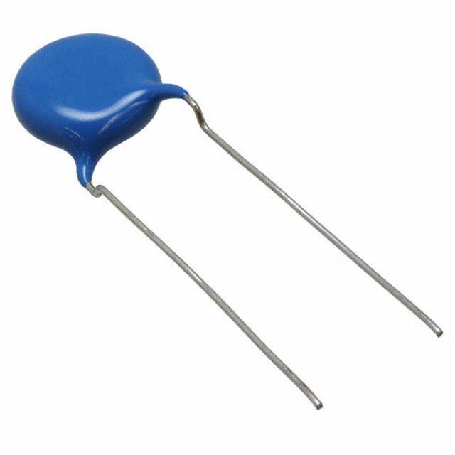
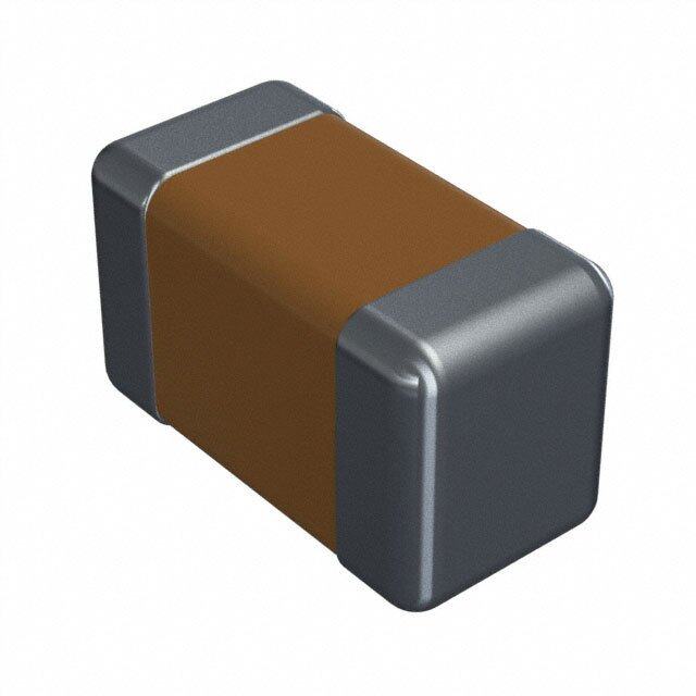
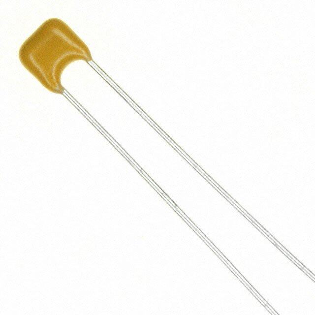
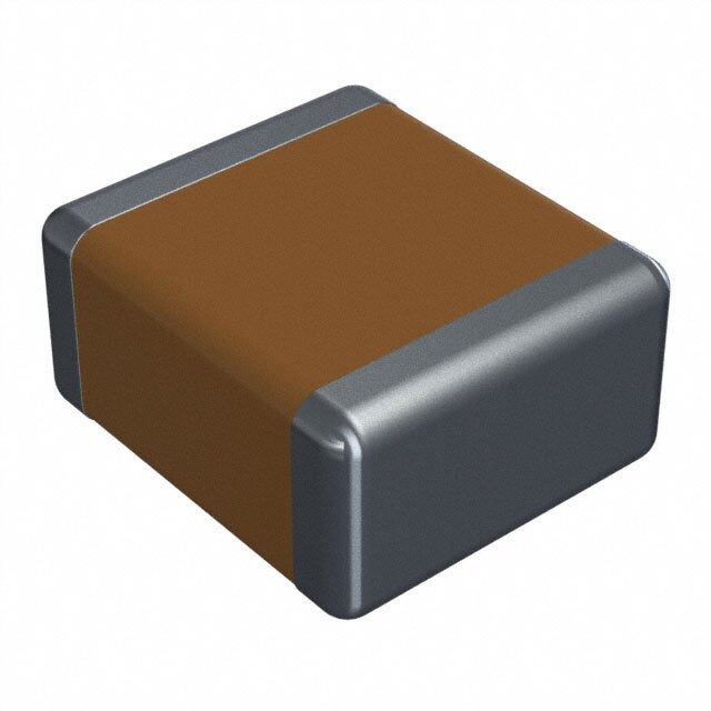
ICGOO电子元器件商城为您提供C951U332MVWDBA7317由Kemet设计生产,在icgoo商城现货销售,并且可以通过原厂、代理商等渠道进行代购。 C951U332MVWDBA7317价格参考¥1.72-¥1.72。KemetC951U332MVWDBA7317封装/规格:陶瓷电容器, 3300pF ±20% 400VAC 陶瓷电容器 Y5U(E) 径向,圆片式。您可以下载C951U332MVWDBA7317参考资料、Datasheet数据手册功能说明书,资料中有C951U332MVWDBA7317 详细功能的应用电路图电压和使用方法及教程。
KEMET的C951U332MVWDBA7317是一款陶瓷电容器,常用于高可靠性及高温环境下的电子电路中。该型号具有较高的耐压和稳定的电气性能,适用于工业控制设备、电源转换模块、汽车电子系统以及通信设备等场景。其优异的温度特性和低损耗特性使其在高频电路和滤波电路中表现出色,能够有效提升系统的稳定性和效率。此外,该电容器也广泛应用于消费类电子产品中的关键电路部分,如电源管理模块和信号处理电路。
| 参数 | 数值 |
| 产品目录 | |
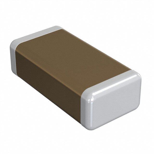
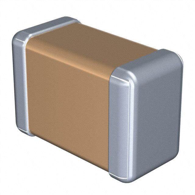
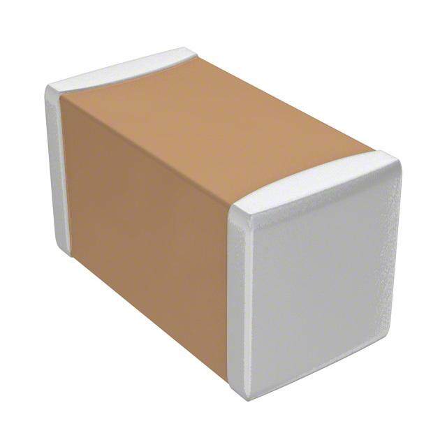
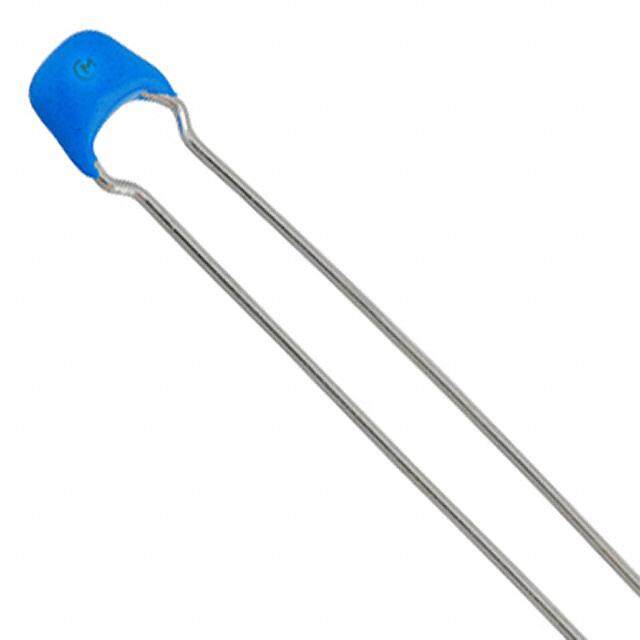
| 描述 | CAP CER 3300PF 400VAC 20% RADIAL瓷片电容器 400volts 3300pF 20% Y5U |
| 产品分类 | |
| 品牌 | Kemet |
| 产品手册 | |
| 产品图片 |
|
| rohs | 符合RoHS无铅 / 符合限制有害物质指令(RoHS)规范要求 |
| 产品系列 | 陶瓷电容器,瓷片电容器,Kemet C951U332MVWDBA7317C900 |
| 数据手册 | http://www.kemet.com/docfinder?Partnumber=C951U332MVWDBA7317 |
| 产品型号 | C951U332MVWDBA7317 |
| 产品 | Safety Ceramic Disc Capacitors |
| 产品种类 | 瓷片电容器 |
| 其它名称 | 399-9513-3 |
| 包装 | 带盒(TB) |
| 厚度(最大值) | - |
| 商标 | Kemet |
| 外壳直径 | 12 mm |
| 大小/尺寸 | 0.472" 直径(12.00mm) |
| 安装类型 | 通孔 |
| 容差 | ±20% |
| 封装 | Ammo Pack |
| 封装/外壳 | 径向,圆盘 |
| 工作温度 | - |
| 工厂包装数量 | 500 |
| 应用 | 安全 |
| 引线形式 | 成型引线 - 扭结 |
| 引线间距 | 0.394"(10.00mm) |
| 引线间隔 | 10 mm |
| 最大工作温度 | + 125 C |
| 最小工作温度 | - 25 C |
| 标准包装 | 500 |
| 温度系数 | Y5U(E) |
| 温度系数/代码 | Y5U |
| 特性 | - |
| 电介质 | Y5U |
| 电压-额定 | 400VAC |
| 电压额定值 | 400 V |
| 电压额定值AC | 400 V |
| 电容 | 3300pF |
| 端接类型 | Radial |
| 等级 | X1Y1 |
| 类 | X1, Y1 |
| 类型 | Safety Standard Ceramic Disc AH Type X1 400VAC/Y1 400VAC |
| 系列 | C900 |
| 高度-安装(最大值) | - |


- 商务部:美国ITC正式对集成电路等产品启动337调查
- 曝三星4nm工艺存在良率问题 高通将骁龙8 Gen1或转产台积电
- 太阳诱电将投资9.5亿元在常州建新厂生产MLCC 预计2023年完工
- 英特尔发布欧洲新工厂建设计划 深化IDM 2.0 战略
- 台积电先进制程称霸业界 有大客户加持明年业绩稳了
- 达到5530亿美元!SIA预计今年全球半导体销售额将创下新高
- 英特尔拟将自动驾驶子公司Mobileye上市 估值或超500亿美元
- 三星加码芯片和SET,合并消费电子和移动部门,撤换高东真等 CEO
- 三星电子宣布重大人事变动 还合并消费电子和移动部门
- 海关总署:前11个月进口集成电路产品价值2.52万亿元 增长14.8%

PDF Datasheet 数据手册内容提取
Radial Leaded Ceramic Disc Capacitors Safety Standard Recognized, C900, Encapsulated, AH Type, X1 400 VAC/Y1 400 VAC (Industrial Grade) Overview KEMET’s 900 series encapsulated radial leaded ceramic With a working voltage of 400 VAC in line-to-line (Class X)and disc capacitors are specifically designed for interference- 400 VAC in line-to-ground (Class Y) applications, these safety suppression AC line filtering applications. Having capacitors meet the impulse test criteria outlined in IEC internationally recognized safety certifications, these Standard 60384. Meeting subclass X1 and Y1 requirements, capacitors are well-suited for applications that require these devices are certified to withstand impulses up to 4 keeping potentially disruptive or damaging line transients KV (X1) and 8 KV (Y1) respectively. These encapsulated and EMI out of susceptible equipment. They are also an devices also meet the flame test requirements outlined in UL ideal solution when needing to suppress line disturbances Standard 94V–0. at the source. Safety Certified Capacitors are classified as either X and/ or Y capacitors. Class X capacitors are primarily used in line-to line (across-the-line) applications. In this application there is no danger of electric shock to humans should the capacitor fail, but could result in a risk of fire. The class Y capacitor is primarily used in line-to-ground (line by-pass) applications. In this application, failure of the capacitor could lead to danger of electric shock. Ordering Information C9 3 1 U 101 J V S D A A 7317 Ceramic Body Lead Capacitance Capacitance Rated Dielectric/ Failure Packaging Spec. Design Lead Config.2 Series Diameter Spacing1 Code (pF) Tolerance Voltage Temp. Char. Rate (C-Spec) C9 = 0 = 7.0 mm 1 = U = Two J = ±5% V = X1 S = SL D = A = Straight A = See Ceramic 1 = 8.0 mm 10.0 mm Safety significant K = ±10% 400 VAC Y = Y5P Disc B = Vertical N/A "Packaging 900 2 = 9.0 mm digits and M = ±20% /Y1 400 W = Y5U Kink C-Spec Series 3 = 10.0 mm number of VAC V = Y5V C = Outside Ordering 4 = 11.0 mm zeroes Kink Options 5 = 12.0 mm Table" 6 = 13.0 mm below 7 = 14.0 mm 1 "Vertical Kink" and "Outside Kink" lead configurations cannot be combined with the bulk/20 mm lead length option (WL20). 20 mm lead length is only available on capacitors ordered with straight leads (lead configuration ordering code "A"). For nonstandard lead length inquiries, please contact KEMET. 2 Bulk packaging lead length availability is dependent upon "Lead Configuration." See "Dimensions" section of this document to verify availability of a specific lead length option. For nonstandard lead length inquiries, please contact KEMET. One world. One KEMET © KEMET Electronics Corporation • P.O. Box 5928 • Greenville, SC 29606 • 864-963-6300 • www.kemet.com C1068_X1_400 VAC_Y1_400 VAC • 6/9/2017 1
Radial Leaded Ceramic Disc Capacitors Safety Standard Recognized, C900, Encapsulated, AH Type, X1 400 VAC/Y1 400 VAC (Industrial Grade) Packaging C-Spec Ordering Options Table Lead Length Packaging Packaging Type (mm)2,3 Ordering Code (C-Spec) 20.0 +1.5/−1.0 (straight leads) Ammo Pack 7317 18.0 +2.0/−0 (preformed leads1) 3.0±1.0 WL30 3.5±1.0 WL35 4.0±1.0 WL40 Bulk Bag 4.5±1.0 WL45 5.0±1.0 WL50 20.0 minimum4 WL20 1 Preformed (crimped) lead configurations include vertical kink, outside kink and inside kink. See "Lead Configurations" and "Ordering Information" sections of this document for further details. 2 "Vertical Kink", "Outside Kink" and "Inside Kink" lead configurations cannot be combined with the bulk/20 mm lead length option (WL20). 20 mm lead length is only available on capacitors with straight leads (lead configuration ordering code "A"). For nonstandard lead length inquiries, please contact KEMET. 3 For nonstandard lead length inquiries, please contact KEMET. 4 Lead length of 20.0 mm minimum only available for straight leads. Benefits • Safety Standard Recognized (IEC 60384-14) • Reliable operation up to 125°C • Class X1/Y1 • 10 mm lead spacing • Lead (Pb)-free and RoHS Compliant • Halogen free • Capacitance offerings ranging from 10 pF up to 10 nF • Available capacitance tolerances of ±5%, ±10% and ±20% • High reliability • Preformed (crimped) or straight lead configurations • Non-polar device, minimizing installation concerns • 100% pure matte tin-plated lead finish allowing for excellent solderability • Encapsulation meets flammability standard UL 94V–0 Applications Typical applications include: • Line-to-line (Class X) filtering • Line-to-ground (Class Y) filtering • Antenna coupling • Primary and secondary coupling (switching power supplies) • Line disturbances suppression (motors and motor controls, relays, switching power supplies, and inverters) © KEMET Electronics Corporation • P.O. Box 5928 • Greenville, SC 29606 • 864-963-6300 • www.kemet.com C1068_X1_400 VAC_Y1_400 VAC • 6/9/2017 2
Radial Leaded Ceramic Disc Capacitors Safety Standard Recognized, C900, Encapsulated, AH Type, X1 400 VAC/Y1 400 VAC (Industrial Grade) Lead Configurations Straight Vertical Kink Outside Kink D T D T D T 3.0 3.0 3.0 Maximum Maximum Maximum 4.0 Maximum 5.0 Maximum LL LL LL F F F S S S Dimensions – Millimeters S D T e ØF Lead Lead Lead Configuration Lead Spacing Body Body Lead Lead Configuration Ordering Code1 Spacing2 Tolerance Diameter2 Thickness Meniscus Diameter Straight A 10.0 ±1.0 See Table 1 - Vertical Kink 3.0 B 10.0 ±1.0 "Product Ordering Codes 0.55±0.1 (Preformed) maximum and Ratings" Outside Kink C 10.0 ±1.0 (Preformed) 1 Lead Configuration is identified in the 13th character of the ordering code. See "Lead Configuration" and "Ordering Information" sections of this document for further details. 2 Body diameter of capacitor will limit available lead spacing and packaging options. See "Product Ordering Codes and Ratings" sections of this document for further details. © KEMET Electronics Corporation • P.O. Box 5928 • Greenville, SC 29606 • 864-963-6300 • www.kemet.com C1068_X1_400 VAC_Y1_400 VAC • 6/9/2017 3
Radial Leaded Ceramic Disc Capacitors Safety Standard Recognized, C900, Encapsulated, AH Type, X1 400 VAC/Y1 400 VAC (Industrial Grade) Approval Standard and Certification No. Safety Standard Standard No. Subclass Working Voltage Certificate No. VDE X1 400 VAC IEC 60384–14 40036417 (ENEC) Y1 400 VAC UL UL 60384–14 and X1 400 VAC E356389 CAN/CSA E60384–14 Y1 400 VAC These devices are VDE/ENEC and UL recognized for antenna coupling and AC line-to-line (Class X) and line-to-ground (Class Y) applications per IEC60384–14 and UL 60384–14. Environmental Compliance These devices are Halogen free and RoHS Compliant. They meet all requirements set forth by both EU and China RoHS directives. General Specifications/Performance Characteristics Dielectric/Temperature Characteristic SL Y5P Y5U Y5V Operating Temperature Range: −40°C to +125°C Capacitance Change with Reference to −1,000 ~ +350 ppm/ ±10% +20%/−55% ~ +30%/−80% +25°C and 0 VDC Applied (TCC): ºC 4,000 VAC Dielectric Withstanding Voltage (60±5 seconds at 25ºC) 30 pF and above: ≥ 1,000 Quality Factor (Q) See “Dissipation Factor” Below 30 pF: ≥ 400 +(20xC)* Dissipation Factor (tanδ) at +25ºC1 See “Quality Factor” 2.50% 2.50% 5.0% 10,000 MΩ Minimum Insulation Resistance (IR) Limit at +25°C (500 VDC applied for 60±5 seconds at 25°C) * C = Nominal capacitance 1 Capacitance and Dissipation Factor (DF) measured under the following conditions: SL: 1 MHz ±100 kHz and 1.0 ±0.2 Vrms X5P, Y5U and Y5V: 1 kHz ±50 Hz and 1.0 ±0.2 Vrms Note: When measuring capacitance, it is important to ensure the set voltage level is held constant. The HP4284 and Agilent E4980 have a feature known as Automatic Level Control (ALC). The ALC feature should be switched to "ON." © KEMET Electronics Corporation • P.O. Box 5928 • Greenville, SC 29606 • 864-963-6300 • www.kemet.com C1068_X1_400 VAC_Y1_400 VAC • 6/9/2017 4
Radial Leaded Ceramic Disc Capacitors Safety Standard Recognized, C900, Encapsulated, AH Type, X1 400 VAC/Y1 400 VAC (Industrial Grade) Table 1 – Product Ordering Codes and Ratings Dimensions (mm) Lead Spacing Dielectric/ KEMET Capacitance Body Body Temp. Capacitance Lead Bulk Ammo Part Number Tolerance Diameter Thickness Char. Diameter Packaging Packaging (Maximum) (Maximum) C901U150JVSD(1)A(2) 15 pF C901U180JVSD(1)A(2) 18 pF C901U200JVSD(1)A(2) 20 pF C901U220JVSD(1)A(2) 22 pF C901U240JVSD(1)A(2) 24 pF 7.0 C901U270JVSD(1)A(2) 27 pF C901U300JVSD(1)A(2) 30 pF C901U330JVSD(1)A(2) 33 pF C901U360JVSD(1)A(2) 36 pF SL C901U390JVSD(1)A(2) 39 pF ±5% 5.0 0.55 ±0.1 10 mm C911U470JVSD(1)A(2) 47 pF C911U500JVSD(1)A(2) 50 pF C911U510JVSD(1)A(2) 51 pF 8.0 C911U560JVSD(1)A(2) 56 pF C911U620JVSD(1)A(2) 62 pF C921U680JVSD(1)A(2) 68 pF C921U750JVSD(1)A(2) 75 pF 9.0 C921U820JVSD(1)A(2) 82 pF C931U101JVSD(1)A(2) 100 pF 10.0 C901U101KVYD(1)A(2) 100 pF C901U151KVYD(1)A(2) 150 pF 7.0 C901U221KVYD(1)A(2) 220 pF C901U331KVYD(1)A(2) 330 pF Y5P ±10% 5.0 0.55 ±0.1 10 mm C911U471KVYD(1)A(2) 470 pF 8.0 C921U561KVYD(1)A(2) 560 pF 9.0 C921U681KVYD(1)A(2) 680 pF C941U102KVYD(1)A(2) 1,000 pF 11.0 C911U102MVWD(1)A(2) 1,000 pF 8.0 C921U152MVWD(1)A(2) 1,500 pF 9.0 C931U222MVWD(1)A(2) 2,200 pF 10.0 Y5U ±20% 5.0 0.55 ±0.1 10 mm C951U332MVWD(1)A(2) 3,300 pF 12.0 C961U392MVWD(1)A(2) 3,900 pF 13.0 C971U472MVWD(1)A(2) 4,700 pF 14.0 C901U102MVVD(1)A(2) 1,000 pF 7.0 C911U152MVVD(1)A(2) 1,500 pF 8.0 Y5V C921U222MVVD(1)A(2) 2,200 pF ±20% 9.0 5.5 0.55 ±0.1 10 mm C941U332MVVD(1)A(2) 3,300 pF 11.0 C951U472MVVD(1)A(2) 4,700 pF 12.0 Capacitance Body Diameter Body Thickness KEMET Part Number Capacitance Lead Diameter Lead Spacing Tolerance (Maximum) (Maximum) (1) To properly complete ordering code, insert the one-digit character code to reflect the required lead configuration: (See "Lead Configuration" section of this document, page 2, for further details.) A = Straight B = Vertical Kink C = Outside Kink (2) To properly complete ordering code, enter the four-digit numeric or alphanumeric "Packaging C-Spec Ordering Code." See "Dimensions" section of this document, page 2, for available options. © KEMET Electronics Corporation • P.O. Box 5928 • Greenville, SC 29606 • 864-963-6300 • www.kemet.com C1068_X1_400 VAC_Y1_400 VAC • 6/9/2017 5
Radial Leaded Ceramic Disc Capacitors Safety Standard Recognized, C900, Encapsulated, AH Type, X1 400 VAC/Y1 400 VAC (Industrial Grade) Table 2 – Performance & Reliability: Test Methods and Conditions Item Specification Test Method Operating Temperature Range -40ºC to +125ºC Between lead The capacitor shall not be damaged when 4,000 VAC(rms) is No failures wires applied between the lead wires for 60 seconds. The terminals (leads) of the capacitor shall be connected together. A metal foil Dielectric is tightly wrapped around the body of the capacitor at a distance of about 3 to 4 mm Strength Body Insulation No failures from each terminal. The capacitor is then MFeotiall about inserted into a container filled with metal 3 to 4 mm balls approximately 1 mm in diameter. 4,000 Metal VAC(rms) is applied for 60 seconds between Balls the capacitor lead wires and metal balls. The insulation resistance shall be measured with 500±50 VDC Insulation Resistance (IR) 10,000 MΩ minimum applied after 60±5 seconds of charging. Capacitance Within specified tolerance Temperature Specification Characteristics Y5P, Y5U DF ≤ 2.5% Y5P, Y5U and Y5V: Capacitance is measured at 1 kHz ±20% and 5 Vrms or less. (20±2°C) Y5V DF ≤ 5.0% SL: Capacitance is measured at 1 MHz ±20% and 1.0±0.2 Vrms Dissipation Factor (DF) or Q (25°C) SL ≥ 30 pF: Q ≥ 1,000 < 30 pF: Q ≥ 400 +(20 x C) C = Nominal capacitance A capacitance measurement is made at each step specified: Temperature Capacitance Step Temperature Characteristics Change 1 +20±2ºC Y5P Within ±10% 2 −25±2ºC Temperature Characteristics Y5U Within +22%/−56% 3 +20±2ºC Y5V Within 4 +85±2ºC ~+30%/−80% 5 +20±2ºC SL −1,000 ~+350 ppmºC Pre-treatment: (+20ºC ~+85ºC) Capacitor is stored at 85±2ºC for 1 hour and then placed at room condition1 for 24±2 hours before measurement. With the termination in its normal position, the specimen is held by its body in such a manner that the axis of the termination is Lead wire or capacitor body shall not Tensile vertical; a tensile force of 10 N is applied to the termination in the break. direction of its axis and acting in a direction away from the body of the specimen. With the termination in its normal position, the specimen is held Terminal by its body in such a manner that the axis of the termination is Strength vertical; a mass force of 5 N is then suspended from the end of the termination. The body of the specimen is then inclined within Lead wire or capacitor body shall not Bending a period of 2 to 3 seconds, through an angle of approximately 90° break. in the vertical plane and then resumed to its initial position over the same period of time; this operation constitutes one bend. One bend immediately followed by a second bend in the opposite direction. 1 “Room Condition” is defined as follows: Temperature: 15 ~ 35°C/Humidity: 45 ~ 75%/Atmospheric Pressure: 86 ~ 106 kPa. © KEMET Electronics Corporation • P.O. Box 5928 • Greenville, SC 29606 • 864-963-6300 • www.kemet.com C1068_X1_400 VAC_Y1_400 VAC • 6/9/2017 6
Radial Leaded Ceramic Disc Capacitors Safety Standard Recognized, C900, Encapsulated, AH Type, X1 400 VAC/Y1 400 VAC (Industrial Grade) Table 2 – Performance & Reliability: Test Methods and Conditions cont'd Item Specification Test Method The lead wire of the capacitor is dipped into molten solder for Lead wire should have a uniform coating 5±0.5 seconds. The depth of immersion is up to 1.5 mm Solderability of solder in the axial direction and over (+5/−0 mm) from the root of lead wires. 3/4 of its circumference. Solder Temperature: Lead free solder (Sn-3Ag – 0.5Cu) 245°C ±5°C. Appearance No visual defect As shown in the figure below, the lead wires are immersed in molten solder up to 1.5 mm (+5/−0 mm) from the end of the epoxy meniscus (root of lead wire). IR 1,000 MΩ Duration/Solder Temperature: 3.5±0.5 seconds/350°C ±10°C or 10±1 seconds/260°C ±5°C Dielectric Per item 1 Strength Thermal Capacitor Screen Soldering Effect 1.5 to (Non-Preheat) 2.0 mm Molten Y5P, Y5U and Y5V: Within ±10% Solder Capacitance SL: Within ±2.5% or ±0.25 pF, whichever Pre-treatment: Capacitor is stored at 85°C ±2°C for 1 hour and is larger. then placed at room condition1 for 24±2 hours before initial measurements. Post-treatment: Capacitor is stored for 1 to 2 hours at room condition1. Capacitor is stored at 120°C +0/−5°C for 60 +0/−5 seconds. Appearance No visual defect Then, as shown in the figure below, the lead wires are immersed in molten solder up to 1.5 mm (+5/−0mm) from the end of the IR 1,000 MΩ epoxy meniscus (root of lead wire). Dielectric Duration/Solder Temperature: 7.5+0/−1 seconds/260°C ±5°C Per item 1 Strength Thermal Capacitor Screen Soldering Effect 1.5 to (Preheat) 2.0 mm Molten Y5P, Y5U and Y5V: Within ±10% Solder Capacitance SL: Within ±2.5% or ±0.25 pF, whichever Pre-treatment: Capacitor is stored at 85°C ±2°C for 1 hour and is larger. then placed at room condition1 for 24±2 hours before initial measurements. Post-treatment: Capacitor is stored for 1 to 2 hours at room condition1. Appearance No visual defect Steady State Humidity: Load Humidity: Temperature Capacitance Characteristics Change Y5P Within ±10% Capacitance Y5U Within ±20% Y5V Within ±30% 90 to 95% humidity at 40°C Within ±2.5% or 90 to 95% humidity at 40°C ±2°C for 500±12 hours with ±2°C for 500±12 hours. Biased Humidity SL ±0.25 pF, whichever full rated voltage applied. is larger. Post Treatment: Post Treatment: Y5P and Y5U: 5.0% maximum Capacitor is stored for 1 to 2 Capacitor is stored for 1 to 2 DF hours at room condition1. Y5V: 7.5% maximum hours at room condition1. SL: Less than 30 pF: Q ≥ 100+10×C/3 Q More than 30 pF: Q ≥ 200 C = Nominal capacitance Y5P, Y5V and Y5U: 3,000 MΩ minimum IR SL: 1,000 MΩ minimum Dielectric No failures Strength 1 “Room Condition” is defined as follows: Temperature: 15 ~ 35°C/Humidity: 45 ~ 75%/Atmospheric Pressure: 86 ~ 106 kPa. © KEMET Electronics Corporation • P.O. Box 5928 • Greenville, SC 29606 • 864-963-6300 • www.kemet.com C1068_X1_400 VAC_Y1_400 VAC • 6/9/2017 7
Radial Leaded Ceramic Disc Capacitors Safety Standard Recognized, C900, Encapsulated, AH Type, X1 400 VAC/Y1 400 VAC (Industrial Grade) Table 2 – Performance & Reliability: Test Methods and Conditions cont'd Item Specification Test Method Appearance No visual defect Impulse Voltage: Each individual capacitor is subjected to three 8 kv impulses prior to life testing. Y5P, Y5V and Y5U: Within ±20% Capacitance Change SL: Within ±3 or ±0.3 pF, Vp UPR Cx tr td whichever is larger. e0.9Vp (uF)(uS)(uS) IR SL3:, 01,0000 M0 MΩ Ωm miniimnimumum oltag0.5Vp UPP 00..01111..52 4467 High V Temperature Life Dielectric tr td Time No failures Strength Capacitors are placed in a circulating air oven for a period of 1,000 hours. The air in the oven is maintained at a temperature of 125°C ±2°C throughout the test. The capacitors are subjected to AC 680 Vrms. Each hour the voltage is increased to AC 1,000 Vrms for 0.1 seconds. The capacitor is exposed to a flame for 15 seconds and then The capacitor flame extinguishes as removed for 15 seconds. This test is repeated for 5 cycles. follows: Capacitor Cycle Time Flame 76 Flame Test 1 ~ 4 30 seconds 38 127 maximum 60 seconds 5 Gas Burner maximum 20º (Unit:mm) The capacitors are individually wrapped in at least one, but not more than two, complete layers of cheesecloth. They are then subjected to 20 discharges. The interval between successive discharges is 5 seconds. The VAC is maintained for 2 minutes after the last discharge. S1 F L1 L2 R C1 C2 C3 CX Ct Vt Tr S2 Vac L3 L4 Oscilloscope C 1 μF ±10% C 0.033 μF ±5% 10 kV 1, 2 3 Active Flammability The cheesecloth should not ignite. L 1.5 Mh ±20% 16A Rod core choke Cx Test capacitor 1-4 R 100 ±2% V VR ±5% AC Ct 3 μF ±5% 10 kV V Rated Voltage R F Fuse, Rated 10A Vt Voltage applied to Ct Vx 5kV time 1 “Room Condition” is defined as follows: Temperature: 15 ~ 35°C/Humidity: 45 ~ 75%/Atmospheric Pressure: 86 ~ 106 kPa. © KEMET Electronics Corporation • P.O. Box 5928 • Greenville, SC 29606 • 864-963-6300 • www.kemet.com C1068_X1_400 VAC_Y1_400 VAC • 6/9/2017 8
Radial Leaded Ceramic Disc Capacitors Safety Standard Recognized, C900, Encapsulated, AH Type, X1 400 VAC/Y1 400 VAC (Industrial Grade) Table 2 – Performance & Reliability: Test Methods and Conditions cont'd Item Specification Test Method The capacitor under test is held into a flame and in a position which best promotes burning. Each specimen is exposed to the flame one time. m Test Specimen m 8 ut bo 200 A 45º ±5mm Tissue The burning time should not exceed 30 Passive Flammability seconds. About 10mm The tissue paper should not ignite. Thick Board Time of exposure to flame: 30 seconds Length of flame: 12±1 mm Gas burner length: 35 mm minimum Inside diameter: 0.5±0.1 mm Outside diameter: 0.9 mm maximum Gas butane gas purity: 95% minimum Appearance No visual defect Temperature Capacitance The capacitor is subjected to 5 temperature cycles. Characteristics Change Temperature Cycle Capacitance SL Within ±5% Dwell Transition Y5P Within ±10% Step Temperature (°C) Time Time Y5U, Y5V Within ±20% (minutes) (minutes) 1 −40 +0/−3 30 Temperature SL ≥30 pF: Q ≥ 350 Cycle <30 pF: Q ≥ 275 2 Room temperature 3 +5/2C 3 3 125 +3/−0 30 C = Nominal DF/Q capacitance 4 Room temperature 3 Y5P DF ≤ 5% Pre-treatment: Capacitor shall be stored at 85±2 for 1 hour then Y5U, Y5V DF ≤ 7.5% placed at room condition1 for 24±2 hours. Post-treatment: Capacitor is stored for 1 to 2 hours at room 3,000 MΩ minimum IR condition1. SL: 1,000 MΩ minimum Dielectric No failures Strength 1 “Room Condition” is defined as follows: Temperature: 15 ~ 35°C/Humidity: 45 ~ 75%/Atmospheric Pressure: 86 ~ 106 kPa. © KEMET Electronics Corporation • P.O. Box 5928 • Greenville, SC 29606 • 864-963-6300 • www.kemet.com C1068_X1_400 VAC_Y1_400 VAC • 6/9/2017 9
Radial Leaded Ceramic Disc Capacitors Safety Standard Recognized, C900, Encapsulated, AH Type, X1 400 VAC/Y1 400 VAC (Industrial Grade) Soldering and Mounting Information Soldering: When soldering this product to a PCB/PWB, do not exceed the solder heat resistance specification of the capacitor. Subjecting this product to excessive heating could reflow the solder joint between the lead and ceramic element and/or may result in thermal shocks that can crack the ceramic element. When soldering these capacitors with a soldering iron, it should be performed under the following conditions: • Temperature of iron-tip: 400ºC maximum • Soldering iron wattage: 50 W maximum • Soldering time: 3.5 seconds maximum Cleaning (ultrasonic cleaning): To perform ultrasonic cleaning, observe the following conditions: • Rinse bath capacity: Output of 20 watts per liter or less • Rinsing time: 5 minute maximum • Do not vibrate the PCB/PWB directly • Excessive ultrasonic cleaning may lead to fatigue destruction of the lead wires Construction Detailed Cross Section Epoxy Encapsulation (0.4 mm Minimum cThickness, Pigment = Blue/UL 94 V-0) Lead Attach Solder (Sn96.5/Ag3/Cu0.5) Dielectric Material (BaTiO) 3 Electrode Electrode (Ag – Glass Frit) (Ag – Glass Frit) Lead Attach Solder Lead Wire (Sn96.5/Ag3/Cu0.5) Core Metal Steel Dielectric Barrier Layer Cu Material 100% Sn (BaTiO) Finish Layer (3-7 µm) 3 © KEMET Electronics Corporation • P.O. Box 5928 • Greenville, SC 29606 • 864-963-6300 • www.kemet.com C1068_X1_400 VAC_Y1_400 VAC • 6/9/2017 10
Radial Leaded Ceramic Disc Capacitors Safety Standard Recognized, C900, Encapsulated, AH Type, X1 400 VAC/Y1 400 VAC (Industrial Grade) Marking These capacitors shall be stamped or laser marked with KEMET's trademark, type designation, capacitor class, rated voltage, rated capacitance and capacitance tolerance codes. In addition, all devices are marked with the recognized approval mark and a date/lot code for traceability. Marking will be supplied either on one side or both sides of the encapsulated capacitor body. All marking shall be legible to allow for clear identification of the component. Marking appears in legible contrast. Illustrated below is an example of the marking format and content. (Two sided marking is limited to capacitors with body diameters ≤ 8.0 mm.) Single Sided Rated Capacitance (3 Numeric Characters) KEMET ID Capacitance Type Designation Tolerance Code (2 Characters) (1 Character) VDE & ENEC Capacitor Class approval marks and Rated Voltage IEC 60384-14 3rd (2005) UL approval mark Date/Lot Code (See Table Below) Double Sided Front Back Rated Capacitance UL approval mark KEMET ID (3 Numeric Characters) Type Designation Capacitance VDE & ENEC (2 Characters) Tolerance Code approval marks (1 Character) IEC 60384-14 3rd Capacitor Class (2005) and Rated Voltage Date/Lot Code (See Table Below) Date/Lot Code Explanation 6 C 6 1234 Manufacturing Month: Last digit of year, e.g., Manufacturing Last 4 digits of 1-9 = Jan - Sept Location Code lot no. A = October 6 = 2016 N = November D = December © KEMET Electronics Corporation • P.O. Box 5928 • Greenville, SC 29606 • 864-963-6300 • www.kemet.com C1068_X1_400 VAC_Y1_400 VAC • 6/9/2017 11
Radial Leaded Ceramic Disc Capacitors Safety Standard Recognized, C900, Encapsulated, AH Type, X1 400 VAC/Y1 400 VAC (Industrial Grade) Packaging Quantities Ammo Pack (Carrier Tape) Capacitor Bulk Bag Body Diameter Code1 Component pitch on carrier tape2 Body Diameter (mm) (Loose) 25.4 mm 7.0 0 8.0 1 9.0 2 1,000 pieces/box 10.0 3 500 pieces/bag 11.0 4 13.0 6 14.0 7 500 pieces/box 15.0 8 1 The "Body Diameter Code" is located in the third character position of the ordering code. This code identifies the maximum diameter of the capacitor body in millimeters. For more information regarding the ordering code, see "Ordering Information" section of this document. 2 For details regarding component pitch on carrier tape, see "Ammo Pack Taping Format" and "Ammo Pack Taping Specifications" sections of this document. © KEMET Electronics Corporation • P.O. Box 5928 • Greenville, SC 29606 • 864-963-6300 • www.kemet.com C1068_X1_400 VAC_Y1_400 VAC • 6/9/2017 12
Radial Leaded Ceramic Disc Capacitors Safety Standard Recognized, C900, Encapsulated, AH Type, X1 400 VAC/Y1 400 VAC (Industrial Grade) Figure 1 - Ammo Pack Taping Format (10 mm Lead Spacing) ∆h 0 ∆h 1 2 P P ∆S T maximum 2 D Marking Side e P 1 F Ød W2 H L 0 W 1 W0 W t t 2 1 P0 ℓ ØD0 Table 3 – Ammo Pack Taping Specifications Lead Spacing 10 mm Lead Style Straight Preformed1 Item Symbol Dimensions (mm) Lead Spacing F 10.0±1.0 Component Pitch P 25.4±2 Sprocket Hole Pitch P 12.7±0.3 0 Sprocket Hole Center to Component Center P 12.7±1.5 2 Sprocket Hole Center to Lead Center P 7.7±1.5 1 Body Diameter D See "Product Ordering Codes and Ratings" section of this document. Component Alignment (side/side ) ∆S 0±2.0 Carrier Tape Width W 18.0+1.0/−0.5 Sprocket Hole Position W 9.0 ±0.5 1 Height to Seating Plane2 (preformed leads1) H N/A 18.0 +2.0/−0 0 Height to Seating Plane2 (straight leads) H 20.0+1.5/−1.0 N/A Lead Protrusion ℓ 2.0 maximum Diameter of Sprocket Hole D 4.0±0.2 0 Lead Diameter φd 0.55±0.1 Carrier Tape Thickness t 0.6±0.3 1 Total Thickness (Carrier Tape, Hold-Down Tape and t 1.5 maximum Lead) 2 ∆h 2.0 maximum Component Alignment (front/back ) 1 ∆h 2.0 maximum 2 Cut Out Length L 11.0 maximum Hold-Down Tape Width W 11.0 minimum 0 Hold-Down Tape Position W 1.5±1.5 2 3.0 maximum for straight lead; not to exceed the bend for preformed1 lead Coating Extension on Leads (meniscus) e configurations. Body Thickness T See "Product Ordering Codes and Ratings" section of this document. 1 Preformed (crimped) lead configurations include vertical kink and outside kink. See "Lead Configurations" and "Ordering Information" sections of this document for further details. 2 Also referred to as "lead length" in this document. © KEMET Electronics Corporation • P.O. Box 5928 • Greenville, SC 29606 • 864-963-6300 • www.kemet.com C1068_X1_400 VAC_Y1_400 VAC • 6/9/2017 13
Radial Leaded Ceramic Disc Capacitors Safety Standard Recognized, C900, Encapsulated, AH Type, X1 400 VAC/Y1 400 VAC (Industrial Grade) Application Notes: Storage and Operating Conditions: The insulating coating of these devices does not form an air and moisture-tight seal. Avoid exposure to moisture and do not use or store these devices in a corrosive atmosphere, especially where chloride gas, sulfide gas, acid, alkali, salt, or the like are present. Before cleaning, bonding or molding these devices, it is important to verify that your process does not affect product quality and performance. KEMET recommends testing and evaluating the performance of a cleaned, bonded or molded product prior to implementing and/or qualifying any of these processes. Store the capacitors where the temperature and relative humidity do not exceed 40 degrees Centigrade and 70% respectively. For optimum solderability, capacitor stock should be used promptly, preferably within 6 months of receipt. Working Voltage: Application voltage (Vp-p or Vo-p) must not exceed the voltage rating of the capacitor. Irregular voltages can be generated for a transient period of time when voltage is initially applied and/or removed from a circuit. It is important to choose a capacitor with a voltage rating greater than or equal to these irregular voltages. Operating Temperature and Self-Generating Heat: The surface temperature of a capacitor should be kept below the upper limit of its rated operating temperature range. Be sure to take into account the heat generated by the capacitor itself. When the capacitor is used in a high-frequency current, pulse current or similar current, it may self-generate heat due to dielectric loss. Temperature rise due to self-generated heating should not exceed 20°C (while operated at an atmosphere temperature of 25°C). Handling - Vibration and Impact: Do not expose these devices or their leads to excessive shock or vibration during use. FAILURE TO FOLLOW THE ABOVE CAUTIONS MAY RESULT, WORST CASE, IN A SHORT CIRCUIT AND CAUSE FUMING OR PARTIAL DISPERSION WHEN THE PRODUCT IS USED. © KEMET Electronics Corporation • P.O. Box 5928 • Greenville, SC 29606 • 864-963-6300 • www.kemet.com C1068_X1_400 VAC_Y1_400 VAC • 6/9/2017 14
Radial Leaded Ceramic Disc Capacitors Safety Standard Recognized, C900, Encapsulated, AH Type, X1 400 VAC/Y1 400 VAC (Industrial Grade) KEMET Electronics Corporation Sales Offi ces For a complete list of our global sales offi ces, please visit www.kemet.com/sales. Disclaimer All product specifi cations, statements, information and data (collectively, the “Information”) in this datasheet are subject to change. The customer is responsible for checking and verifying the extent to which the Information contained in this publication is applicable to an order at the time the order is placed. All Information given herein is believed to be accurate and reliable, but it is presented without guarantee, warranty, or responsibility of any kind, expressed or implied. Statements of suitability for certain applications are based on KEMET Electronics Corporation’s (“KEMET”) knowledge of typical operating conditions for such applications, but are not intended to constitute – and KEMET specifi cally disclaims – any warranty concerning suitability for a specifi c customer application or use. The Information is intended for use only by customers who have the requisite experience and capability to determine the correct products for their application. Any technical advice inferred from this Information or otherwise provided by KEMET with reference to the use of KEMET’s products is given gratis, and KEMET assumes no obligation or liability for the advice given or results obtained. Although KEMET designs and manufactures its products to the most stringent quality and safety standards, given the current state of the art, isolated component failures may still occur. Accordingly, customer applications which require a high degree of reliability or safety should employ suitable designs or other safeguards (such as installation of protective circuitry or redundancies) in order to ensure that the failure of an electrical component does not result in a risk of personal injury or property damage. Although all product–related warnings, cautions and notes must be observed, the customer should not assume that all safety measures are indicted or that other measures may not be required. KEMET is a registered trademark of KEMET Electronics Corporation. © KEMET Electronics Corporation • P.O. Box 5928 • Greenville, SC 29606 • 864-963-6300 • www.kemet.com C1068_X1_400 VAC_Y1_400 VAC • 6/9/2017 15
Mouser Electronics Authorized Distributor Click to View Pricing, Inventory, Delivery & Lifecycle Information: K EMET: C911U102MVWDAA7317 C911U102MVWDAAWL20 C911U102MVWDAAWL35 C911U102MVWDAAWL40 C911U102MVWDAAWL45 C911U102MVWDBA7317 C911U102MVWDBAWL20 C911U102MVWDBAWL35 C911U102MVWDBAWL40 C911U102MVWDBAWL45 C911U102MVWDCA7317 C911U102MVWDCAWL20 C911U102MVWDCAWL35 C911U102MVWDCAWL40 C911U102MVWDCAWL45 C911U152MVVDAA7317 C911U152MVVDAAWL20 C911U152MVVDAAWL35 C911U152MVVDAAWL40 C911U152MVVDAAWL45 C911U152MVVDBA7317 C911U152MVVDBAWL20 C911U152MVVDBAWL35 C911U152MVVDBAWL40 C911U152MVVDBAWL45 C911U152MVVDCA7317 C911U152MVVDCAWL20 C911U152MVVDCAWL35 C911U152MVVDCAWL40 C911U152MVVDCAWL45 C911U470JVSDAA7317 C911U470JVSDAAWL20 C911U470JVSDAAWL35 C911U470JVSDAAWL40 C911U470JVSDAAWL45 C911U470JVSDBA7317 C911U470JVSDBAWL20 C911U470JVSDBAWL35 C911U470JVSDBAWL40 C911U470JVSDBAWL45 C911U470JVSDCA7317 C911U470JVSDCAWL20 C911U470JVSDCAWL35 C911U470JVSDCAWL40 C911U470JVSDCAWL45 C911U471KVYDAA7317 C911U471KVYDAAWL20 C911U471KVYDAAWL35 C911U471KVYDAAWL40 C911U471KVYDAAWL45 C911U471KVYDBA7317 C911U471KVYDBAWL20 C911U471KVYDBAWL35 C911U471KVYDBAWL40 C911U471KVYDBAWL45 C911U471KVYDCA7317 C911U471KVYDCAWL20 C911U471KVYDCAWL35 C911U471KVYDCAWL40 C911U471KVYDCAWL45 C911U500JVSDAA7317 C911U500JVSDAAWL20 C911U500JVSDAAWL35 C911U500JVSDAAWL40 C911U500JVSDAAWL45 C911U500JVSDBA7317 C911U500JVSDBAWL20 C911U500JVSDBAWL35 C911U500JVSDBAWL40 C911U500JVSDBAWL45 C911U500JVSDCA7317 C911U500JVSDCAWL20 C911U500JVSDCAWL35 C911U500JVSDCAWL40 C911U500JVSDCAWL45 C911U510JVSDAA7317 C911U510JVSDAAWL20 C911U510JVSDAAWL35 C911U510JVSDAAWL40 C911U510JVSDAAWL45 C911U510JVSDBA7317 C911U510JVSDBAWL20 C911U510JVSDBAWL35 C911U510JVSDBAWL40 C911U510JVSDBAWL45 C911U510JVSDCA7317 C911U510JVSDCAWL20 C911U510JVSDCAWL35 C911U510JVSDCAWL40 C911U510JVSDCAWL45 C911U560JVSDAA7317 C911U560JVSDAAWL20 C911U560JVSDAAWL35 C911U560JVSDAAWL40 C911U560JVSDAAWL45 C911U560JVSDBA7317 C911U560JVSDBAWL20 C911U560JVSDBAWL35 C911U560JVSDBAWL40 C911U560JVSDBAWL45