ICGOO在线商城 > BH1772GLC-E2
 Datasheet下载
- 型号: BH1772GLC-E2
- 制造商: ROHM Semiconductor
- 库位|库存: xxxx|xxxx
- 要求:
| 数量阶梯 | 香港交货 | 国内含税 |
| +xxxx | $xxxx | ¥xxxx |
查看当月历史价格
查看今年历史价格
BH1772GLC-E2产品简介:
ICGOO电子元器件商城为您提供BH1772GLC-E2由ROHM Semiconductor设计生产,在icgoo商城现货销售,并且可以通过原厂、代理商等渠道进行代购。 提供BH1772GLC-E2价格参考¥63.51-¥71.96以及ROHM SemiconductorBH1772GLC-E2封装/规格参数等产品信息。 你可以下载BH1772GLC-E2参考资料、Datasheet数据手册功能说明书, 资料中有BH1772GLC-E2详细功能的应用电路图电压和使用方法及教程。
| 参数 | 数值 |
| 产品目录 | |
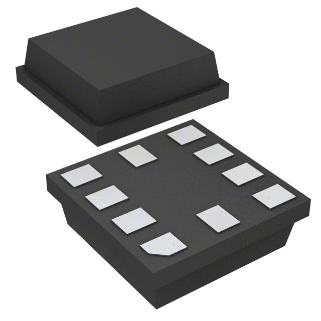
| 描述 | IC SENSOR LIGHT AND PROXIMITY |
| 产品分类 | |
| 品牌 | Rohm Semiconductor |
| 数据手册 | |
| 产品图片 |
|
| 产品型号 | BH1772GLC-E2 |
| rohs | 无铅 / 符合限制有害物质指令(RoHS)规范要求 |
| 产品系列 | - |
| 传感器类型 | 光线和近程 |
| 供应商器件封装 | * |
| 其它名称 | BH1772GLC-E2TR |
| 包装 | 带卷 (TR) |
| 安装类型 | 表面贴装 |
| 封装/外壳 | 10-VFLGA |
| 工作温度 | -40°C ~ 85°C |
| 带接近传感器 | 是 |
| 标准包装 | 3,000 |
| 波长 | 550nm |
| 电压-电源 | 2.3 V ~ 3.6 V |
| 类型 | 环境 |
| 输出类型 | I²C |


_renders/IS42S32800D-6BLI.jpg)


- 商务部:美国ITC正式对集成电路等产品启动337调查
- 曝三星4nm工艺存在良率问题 高通将骁龙8 Gen1或转产台积电
- 太阳诱电将投资9.5亿元在常州建新厂生产MLCC 预计2023年完工
- 英特尔发布欧洲新工厂建设计划 深化IDM 2.0 战略
- 台积电先进制程称霸业界 有大客户加持明年业绩稳了
- 达到5530亿美元!SIA预计今年全球半导体销售额将创下新高
- 英特尔拟将自动驾驶子公司Mobileye上市 估值或超500亿美元
- 三星加码芯片和SET,合并消费电子和移动部门,撤换高东真等 CEO
- 三星电子宣布重大人事变动 还合并消费电子和移动部门
- 海关总署:前11个月进口集成电路产品价值2.52万亿元 增长14.8%

.jpg)


PDF Datasheet 数据手册内容提取
Optical Proximity Sensor ICs 1chip Optical Proximity + Ambient Light Sensor IC BH1772GLC No.12100EFT12 ●Descriptions BH1772GLC is the IC into which optical proximity sensor and digital ambient light senor are unified. Proximity sensor part detects the human or object approach by reflection of infrared LED(IrLED) light. Ambient light sensor part can detect the wide range illuminance from the dark up to under direct sun light. The illuminant intensity of LCD display and keypad can be adjusted, so lower current consumption or higher visibility are possible. ●Features 1) Correspond to I2C bus interface ( f/s mode support ) 2) Low Current by power down function 3) Correspond to 1.8V logic interface 4) ALS spectral responsibility is approximately human eye response ( Peak wavelength : typ. 550nm ) 5) Correspond to wide range of light intensity ( 1-65535 lx range ) 6) Rejecting 50Hz/60Hz light noise (ALS function) 7) Built in ambient light cancelation (Proximity sensor function) 8) Built in configurable IrLED current driver ●Applications Mobile phone, DSC, Portable game, Camcoder, PDA, LCD display etc. ●Absolute Maximum Ratings ( Ta = 25℃ ) Parameter Symbol Ratings Units VCC, Supply Voltage Vccmax 4.5 V VSDAmax, VSCLmax, SDA,SCL,GNDNC Terminal Voltage 4.5 V VGNDNCmax LEDC,INT Terminal Voltage VLEDCmax, VINTmax 7 V Operating Temperature Topr -40~85 ℃ Storage Temperature Tstg -40~100 ℃ SDA, INT Sink Current Imax 7 mA Power Dissipation Pd 250※ mW ※ 70mm × 70mm × 1.6mm glass epoxy board. Decreasing rate is 3.33mW/℃ for operating above Ta=25℃ ●Operating Conditions Ratings Parameter Symbol Units Min. Typ. Max. VCC Voltage Vcc 2.3 2.5 3.6 V LEDC Terminal Voltage Vledc 0.7 2.5 5.5 V www.rohm.com 1/29 2012. 06 - Rev.F © 2012 ROHM Co., Ltd. All rights reserved.
BH1772GLC Technical note ●Electrical characteristics ( Vcc = 2.5V, Ta = 25℃, unless otherwise noted. ) Limits Parameter Symbol Units Conditions Min. Typ. Max. Ev = 100 lx ※1 Average current when ALS_CONTROL Supply current for ALS Icc1 - 90 180 μA register(40h) = ” 03h ” and the other registers are default. Average current when PS_CONTROL Supply current for PS Icc2 - 90 180 μA register(41h) = ” 03h ” and the other registers are default. Supply current Icc3 - 6.5 8.5 mA for PS during driving LED current ALS & PS standby Standby mode current Icc4 - 0.8 1.5 μA No Input Light ALS measurement time tMALS - 100 125 ms H-Resolution mode ALS measurement accuracy S/A 0.85 1.0 1.15 Times Sensor out / Actual lx, Ev = 1000 lx ※1 ALS dark ( 0 lx ) sensor out ALS0 0 0 2 count H-Resolution mode PS sensor out PS0 0 0 30 count Ambient irradiance = 0μW/cm2 (No proximity object) PbyS psreonxsimorit yo uotb (jIercrat d=i a3n2c4eu W /cm2) PS324u 120 128 136 count Ambient irradiance = 0μW/cm2 ILED pulse duration twILED - 200 250 μs PS measurement time tMPS - 10 12.5 ms LEDC terminal sink current ILED register(42h) ILEDC 18 20 22 mA at LEDC terminal voltage = 1.3V [2:0] = ” 010 ” INT output ‘L’ Voltage VINT 0 - 0.4 V IINT = 3mA SCL SDA input 'H' Voltage VIH 1.26 - - V SCL SDA input 'L' Voltage VIL - - 0.54 V SCL SDA input 'H'/’L’ Current IIHL -10 - 10 μA I2C SDA output 'L' Voltage VOL 0 - 0.4 V IOL = 3mA ※1 White LED is used as optical source www.rohm.com 2/29 2012. 06 - Rev.F © 2012 ROHM Co., Ltd. All rights reserved.
BH1772GLC Technical note ●I2C bus timing characteristics ( Vcc = 2.5V, Ta = 25℃, unless otherwise noted. ) Symb Limits Parameter Units Conditions ol Min. Typ. Max. I2C SCL Clock Frequency f 0 - 400 kHz SCL I2C Hold Time ( Repeated ) t 0.6 - - μs START Condition HD;STA I2C 'L' Period of the SCL Clock t 1.3 - - μs LOW I2C 'H' Period of the SCL Clock t 0.6 - - μs HIGH I2C Set up time t 0.6 - - μs for a Repeated START Condition SU;STA I2C Data Hold Time t 0 - - μs HD;DAT I2C Data Setup Time t 100 - - ns SU;DAT I2C Set up Time t 0.6 - - μs for STOP Condition SU;STO I2C Bus Free Time between t 1.3 - - μs a STOP and START Condition BUF I2C Data Valid Time t - - 0.9 μs VD;DAT I2C Data Valid Acknowledge Time t - - 0.9 μs VD;ACK www.rohm.com 3/29 2012. 06 - Rev.F © 2012 ROHM Co., Ltd. All rights reserved.
BH1772GLC Technical note ●Package outlines A C Production code Lot No. WLGA010V28 www.rohm.com 4/29 2012. 06 - Rev.F © 2012 ROHM Co., Ltd. All rights reserved.
BH1772GLC Technical note ●Reference Data 1.2 64 100000 56 1.0 10000 Ratio 000...468 Measurement Result 1234464208 Measurement Result1100000 10 0.2 8 0.0 0 1 400 500 600 700 800 900 1000 1100 0 8 16 24 32 40 48 56 64 1 10 100 1000 10000 100000 Wavelength [ nm ] Illuminance [ lx ] Illuminance [ lx ] Fig.2 Illuminance - Fig.3 Illuminance - Fig.1 ALS Spectral Response ALS Measur ement Result ALS Measurement Result 2 1.2 1.2 10 1 1 1pin 8 0.8 - + 0.8 sult 蛍光灯白熱灯感度比 Ratio 0.6 Ratio 0.6 - 1- p in ment Re 6 0.4 0.4 ure 4 0.2 - + 0.2 + Meas 2 + 0 0 -90 -60 -30Angle 0[ deg ]30 60 90 -90 -60 -30 0 30 60 90 0-40 -20 0 20 40 60 80 100 Angle [ deg ] Ta [ ℃ ] Fig .4 ALS Directional Characteristics 1 Fig.5 ALS Directional Characteristics 2 Fig.6 ALS Dark Response 1.2 200 Fluorescent Light 1 Incandescent uA ]150 0.8 Light ent [ Halogen Light em o ur100 Rati 0.6 Kripton Light Meas @ 0.4 Artifical Sun C 50 Light C I 0.2 White LED 0 2 2.5 3 3.5 4 0 0 0.5 R1atio 1.5 2 VCC [ V ] -40 -20 0 20 40 60 80 100 Ta [ ℃ ] Fig.8 ALS Light Source Dependency Fig.9 VCC - ICC Fig.7 ALS Measurement Accuracy ( Fluorescent Light is set to '1' ) ( During ALS measurement ) Temperature Dependency 1.2 1.20 1.2 1 1.00 1 1pin 0.8 0.80 0.8 - + Ratio 0.6 Ratio0.60 Ratio0.6 0.4 0.40 0.4 - + 0.2 0.2 0.20 0 0 2.2 2.4 2.6 2V.8CC 3[ V ]3.2 3.4 3.6 3.8 0.00400 500 600 700 800 900 1000 1100 -90 -60 -30 0 30 60 90 Wavelength [nm] Angle [ deg ] Fig.10 ALS Measurement Result Fig.11 PS Spectral Response Fig.12 PS Directional Characteristics 1 VCC Dependency www.rohm.com 5/29 2012. 06 - Rev.F © 2012 ROHM Co., Ltd. All rights reserved.
BH1772GLC Technical note 1.2 260 200 240 1 220 200 uA ]150 0.8 180 nt [ Ratio 00..46 - 1- pin PS_DATAOUT 111102460000 @ Measureme100 + 80 C 50 0.2 60 IC + 40 0 20 0 0 -90 -60 -30 0 30 60 90 0.001 0.01 0.1 1 10 100 1000 2.2 2.4 2.6 2.8 3 3.2 3.4 3.6 3.8 Angle [ deg ] VCC [ V ] Irradiance(mW/cm2] Fig.15 VCC - ICC Fig.13 PS Directional Characteristics 2 Fig.14 Irradiance – PS_DATAOUT ( During PS measurement ) 10 240 24 200 20 A ] N [ u LEDC[mA] 112600 LEDC[mA] 1126 OWER DOW 1 I 80 I 8 @ P C C 40 4 I 0 0 0.1 0 1 2 3 4 5 6 0 1 2 3 4 5 6 -40 -20 0 20 40 60 80 100 VLEDC [V] VLEDC [V] Ta [ ℃ ] Fig.18 VCC – ICC@0 Lx Fig.16 VLEDC – ILEDC@ ILED is set Fig.17 VLEDC – ILEDC@ ILED is set ( POWER DOWN ) 200mA by ILED register 20mA by ILED register ILED=200mA 90%White paper 150 200 160 ILED=100mA Human hand unt]140 unt] 160 ILLEEDD =: S20IM0m-0A3 0ST unt]120 LREeDfle :c StoIrM : -030ST OUT [co130 OUT [co 120 Cbaenedtnw tSeeIerM nto- B0 C3He01nS7tTe7r2 :G 1L0Cm m OUT [co 80 1Cbaen8edt%nw tSKeeIeroM ndto- aB0 kC3H eG01nSr7taTe7y r2c :Ga 1rLd0C m m TA120 A 80 A A T T PS_D110 PS_DA 40 18%Kodak GrayCard PS_DA 40 ILED=50mA 100 0 0 -40 -20 0 20 40 60 80 100 0 50 100 150 0 50 100 150 Ta [℃] Object Distance [mm] Object Distance [mm] Fig.19 PS sensor out Fig.20 Object Distance – PS_DATAOUT Fig.21 Object Distance – PS_DATAOUT Temperature Dependency of different reflector of different ILED (Irradiance by Proximity object = 324μW/cm2) 160 SIM-040ST 200 A=5mm ILED=200mA ILED=200mA OUT [count]18200 R1Cbae8neet%dfnwl etIKeenceroft rondtaor ar B e:kC Hd eG 1Lnr7Etae7yDr2c :Ga 1rLd0C m m OUT [count] 112600 A=A1=02Am0=mm3m0mm LR1CbaEe8neet%dDfnwl et IKee:nc erofSt rondtaIorM ar B e:kC -Hd 0 eG 13nLr70tEae7SyDr2Tc :Ga ArLd C A A 80 A=50mm T SIM-030ST T A A A=70mm D 40 D S_ S_ 40 P P 0 0 0 50 100 150 0 50 100 150 Object Distance [mm] Object Distance [mm] Fig.22 Object Distance – PS_DATAOUT Fig.23 Object Distance – PS_DATAOUT of different Infrared LED of different distance between BH1772GLC and SIM-030ST www.rohm.com 6/29 2012. 06 - Rev.F © 2012 ROHM Co., Ltd. All rights reserved.
BH1772GLC Technical note ●I2C bus communication 1) Slave address "0111000" 2) Main write format 1. Case of “Indicate register address” Slave Address W Indicate register address ST ACK ACK SP 0111000 0 010XXXXX 2. Case of "write to data register after indicating register address" Slave Address W Indicate register address ST ACK ACK 0111000 0 010XXXXX Data specified at register address Data specified at register address ACK ・・・・・・ ACK ACK SP field field + N BH1772GLC continues to write data with address increments until master issues stop condition. Write cycle is 40h - 41h - 42h - 43h - 44h - 45h - 46h – 52h ……… 5Dh – 5Eh - 40h ……… Ex ) If register address field is 45h, then BH1772GLC writes data like seeing in below. 45h - 46h -52h ……… 5Dh – 5Eh - 40h………It is continued until master issues stop condition. 3) Main read format 1. Case of read data after indicate register address and read data ( Master issues restart condition ) Slave Address W Indicate register address ST ACK ACK 0111000 0 010XXXXX Slave Address R Data specified at register address ST ACK ACK 0111000 1 field Data specified at register address Data specified at register ACK ・・・・・・ ACK NACK SP field + 1 address field + N 2. Case of read data after selecting register address Slave Address R Data specified at register address ST ACK ACK 0111000 1 field Data specified at register address Data specified at register address ACK ・・・・・・ ACK NACK SP field + 1 field + N BH1772GLC outputs data from specified address field until master issues stop condition. Read cycle is 40h - 41h - 42h - 43h - 44h - 45h - 46h – 4Ah ……… 5Dh – 5Eh - 40h ……… Ex ) If register address field is 4Ch, then BH1772GLC outputs data like seeing in below. 4Ch - 4Dh -4Eh ……… 5Dh – 5Eh - 40h………It is continued until master issues stop condition. from master to slave from slave to master BH1772GLC operates as I2C bus slave device. ※ Please refer formality I2C bus specification of NXP semiconductors ※ www.rohm.com 7/29 2012. 06 - Rev.F © 2012 ROHM Co., Ltd. All rights reserved.
BH1772GLC Technical note ●Block diagram and block explanation VDD LE D IrLED VCC LEDC Proximity Sensor IrLED LED PS Data Driver PGuelns.e CLoongtircol INT INT interface Registers DC light Linear / rejection Linear Log Amp ADC converter Reflector PD_PS GND_LED POR Timing Controller OSC I2C SDA 16bit ALS Interface Ambien t ADC CLoongticrol SCL PD_ALS Light Ambient Light Sensor I2C Interface GND GNDNC I2C bus interface. 1.8V logic interface is supported. POR Power on reset function. OSC Internal oscillator. Timing controller Internal management block for proximity sensor and ambient light sensor. INT interface INT terminal control block. Details are on Page 13 - 14 DATA registers Register for strage of measurement results or commands. Details are on Page 15. PS control logic This block controls proximity sensor analog block LED Pulse Gen LED current generator. LED current value is configurable by ILED( 42h ) register. IrLED Driver IrLED driver block. PD_ALS Photo diode for ambient light sensor. Peak wavelength is approximately 550nm. 16bit ADC AD converter for ALS. ALS control logic This block controls ambient light sensor analog block. PD_PS Photo diode for proximity sensor. Peak wavelength is approximately 850nm. DC light rejection Amp DC light is rejected in this block. And generated Infrared pulse is passed to linear ADC block. Linear ADC AD converter for proximity sensor. Detection range is very wide ( 1μW/cm2 - 100mW/cm2 ). Linear/Log converter Linear to logarithm converter for proximity sensor. Output data is 8bit. PS irradiance calculation example is on Page 23. www.rohm.com 8/29 2012. 06 - Rev.F © 2012 ROHM Co., Ltd. All rights reserved.
BH1772GLC Technical note ●Example of application circuit diagram If you do not use the INT pin, please connect to GND or opening (non connect). Regarding NC1 and NC2, please connect to VDD_LED or open (non connect). 1) Standard application circuit example VDD_LED 2.5 - 5.5V (ex. SIM-030ST(Rohm)) 2.3 – 3.6V IrLED (ex. 0.1μF) (ex. 10μF) VCC 1.65 – 5.5V 6 LED C 3 Proximity Sensor NC1 2 IrLED LPEuDls e PS Data INT NC2 1 Driver Gen CLoongtircol INT 5 Registers interface DreCje lci gthiotn LAinDeCar LinLeoagr / 1.65 - 3.6V Micro Amp converter Controller PD_PS POR or Timing Controller OSC Baseband SCL Processor 8 I2C SDA 16bit ALS Interface 9 ADC Control Logic PD_ALS Ambient Light Sensor 4 7 10 GND_LED GND GNDNC 2) In case of extending proximity sensor detection distance BH1772GLC can drive maximum 200mA(Typ) current. By adding simple external circuit, it is possible to increase IrLED current and to extend detection distance. In case of driving large current for IrLED, note that the current value must not be over the absolute maximum rating for IrLED. VDD_LED 4.5 - 5.5V 2.3 – 3.6V 1kOhm (ex. 0.1μF) (ex. 10μF) VCC 1.65 – 5.5 V PMOS 6 LED C 3 Proximity Sensor NC1 2 IrLED LPEuDls e PS Data INT NC2 1 Driver Gen CLoongtircol INT 5 interface IrLED DreCje lci gthiotn LAinDeCar LinLeoagr / Registers 1.65 - 3.6V Micro Amp converter Controller (ex. SIM-030ST PD_PS POR or (Ro hm)) Timing Controller OSC Baseband R1 SCL Processor 8 I2C SDA 16bit ALS Interface 9 ADC Control Logic PD_ALS Ambient Light Sensor 4 7 10 GND_LED GND GNDNC www.rohm.com 9/29 2012. 06 - Rev.F © 2012 ROHM Co., Ltd. All rights reserved.
BH1772GLC Technical note ●Terminal description PIN Terminal Name Equivalent Circuit Function No. Terminal for internal test. Non connect or pull up to VDD_LED ( external IrLED anode terminal ) 1 NC1 Terminal for internal test. Non connect or pull up to VDD_LED ( external IrLED anode terminal ) 2 NC2 Nch open drain LED current output terminal. LED current and emitting interval is defined by internal register. Register value is possible to configure by 3 LEDC I2C bus. GND terminal for LED driver 4 GND_LED Nch open drain output. Interrupt setting is defined by internal register. Register value is possible to configure by I2C bus. 5 INT Power supply terminal 6 VCC GND terminal 7 GND I2C bus Interface SCL terminal 8 SCL I2C bus Interface SDA terminal 9 SDA Non connect or pull down to GND VCC 10 GNDNC www.rohm.com 10/29 2012. 06 - Rev.F © 2012 ROHM Co., Ltd. All rights reserved.
BH1772GLC Technical note ●Proximity sensor measurement sequence The below figure shows proximity sensor measurement sequence. First PS measurement is triggered by I2C bus master writes measurement command to PS_CONTROL register ( 41h ). 1. Forced mode PS measurement is done only 1time and PS trigger bit ( 44h<0> ) is overwritten from 'H' to 'L' after PS measurement complete. PS measurement is re-started by master writes PS trigger bit to 'H'. 2. Stand alone mode PS measurement is continuously done until master select the other mode. Measurement interval is defined at PS_MEAS_RATE register ( 45h ). LED LED start start measurement measurement PS meas rate tMPS twILED twILED : LED current pulse duration, please refer P2 ( Electrical Characteristics ). tMPS : Proximity sensor measurement time, please refer P2 ( Electrical Characteristics ). Measurement result is generated in this term. PS meas rate : In case of stand alone mode, It is defined at PS_MEAS_RATE register ( 45h ). In case of forced mode, it means the term until overwriting PS trigger bit to ‘H’. ●Ambient light sensor measurement sequence The below figure shows ambient light sensor measurement sequence. First ALS measurement is triggered by I2C bus master writing measurement command to ALS_CONTROL register ( 40h ). 1. Forced mode ALS measurement is done only 1time and ALS trigger bit( 44h<1> ) is overwritten from 'H' to 'L' after ALS measurement is completed. ALS measurement is re-started by master writes ALS trigger bit to 'H'. 2. Stand alone mode ALS measurement is continuously done until master select the other mode. Measurement interval is defined at ALS_MEAS_RATE register ( 46h ). If ALS rate disable bit ( 46h<7> ) is ‘H’, there is no interval between measurement. start start measurement measurement ALS meas rate tMALS tMALS : Ambient light sensor measurement time, please refer P2 ( Electrical Characteristics ). Measurement result is generated in this term. ALS meas rate: In case of stand alone mode, It is defined at ALS_MEAS_RATE register ( 46h ) In case of forced mode, it means the term until overwriting ALS trigger bit to ‘H’. www.rohm.com 11/29 2012. 06 - Rev.F © 2012 ROHM Co., Ltd. All rights reserved.
BH1772GLC Technical note ●Interrupt function Interrupt function compares ALS or PS measurement result to preset interrupt threshold level. PS uses one threshold level or two threshold level ( in hysteresis mode ) and ALS uses two threshold level (upper and lower ). Interrupt status is monitored by INT pin or ALS_PS_STATUS register ( 4Eh ) and Interrupt function is able to be controlled by INTERRUPT register ( 52h ). Interrupt threshold is defined at ALS_TH_UP and ALS_TH_LOW and PS_TH_H and PS_TH_L registers ( 53h, 56 - 59h, 5Ch ). PS_TH_L registers is effective when PS hysteresis bit ( 52h<4> ) is ‘H’. Interrupt persistence function is defined at PERSISTENCE register ( 5Bh ). INT pin is Nch open drain terminal so this terminal should be pull-up to some kind of voltage source by an external resister. Maximum sink current rating of this terminal is 7mA. There are two output modes about interrupt function ( latched mode and unlatched mode ). In case of using ALS and PS interrupt functions at the same time, latch mode is recommended. INT terminal is high impedance when VCC is supplied. INT terminal becomes inactive by setting INTERRUPT register (52h)[1:0] to “00”. ( It is not worked during power down mode. Power down mode means ALS_CONTROL(40h)<1>=’0’ and PS_CONTROL(41h)<1> = ‘0’.) INT terminal keeps just previous state which power down command is sent. So to set INT terminal to high impedance is recommended. VCC current(approximately 25μA at VCC=2.5V) is consumed during INT terminal is ‘L’. There are two method to set INT terminal to high impedance. 1) Send software reset command. (Write ‘H’ to ALS_CONTROL(40h)<2>. Software reset is also worked during power down. All registers are initialized by software reset command.) 2) Write “000” to INTERRUPT register(52h)<2:0>. ex1) In case of using only PS ‘H’ threshold ( INTERRUPT register 52h<4> : ‘0’ ) In case of unlatch mode if the measurement value exceeds the PS interrupt threshold ‘H’ value, the interrupt becomes active. And if the measurement value goes below the threshold, the interrupt becomes inactive. In case of latch mode once the interrupt becomes active, it keeps the status until end of measurement after INTERRUPT register is read. In case of persistence function is set to active, if the interrupt is inactive, it keeps inactive status until the measurement value is beyond the threshold ‘H’ value continuously. If the interrupt is active, it keeps active status until the measurement value is below threshold ‘H’ value continuously or until end of measurement after INTERRUPT register is read. Master reads INTERRUPT register Latch mode Unlatch mode Unlatch mode persistence = 2 active inactive PS interrupt threshold ‘H’ level Sequential measurement result time www.rohm.com 12/29 2012. 06 - Rev.F © 2012 ROHM Co., Ltd. All rights reserved.
BH1772GLC Technical note ex2 ) In case of using PS ‘H/L’ threshold ( INTERRUPT register 52h<4> : ‘1’ ) In case of unlatch mode if the measurement value exceeds the PS interrupt threshold ‘H’ value, the interrupt becomes active. And if the measurement value goes below the threshold ‘L’ value, the interrupt becomes inactive. In case of latch mode once the interrupt becomes active, it keeps the status until end of measurement after INTERRUPT register is read. In case of persistence function is set to active, if the interrupt is inactive, it keeps inactive status until the measurement value is beyond the threshold ‘H’ value continuously. If the interrupt is active, it keeps active status until the measurement value is below threshold ‘L’ value continuously or until end of measurement after INTERRUPT register is read. Master reads INTERRUPT register Latch mode Unlatch mode Unlatch mode persistence = 2 active inactive PS interrupt threshold ‘H’ level PS interrupt threshold ‘L’ level SSeeqquueennttiiaall mmeeaassuurreemmeenntt rreessuulltt time www.rohm.com 13/29 2012. 06 - Rev.F © 2012 ROHM Co., Ltd. All rights reserved.
BH1772GLC Technical note ex3 ) Ambient light sensor interrupt function In case of unlatch mode if the measurement value is within the range set by ALS interrupt threshold ‘H’ and ‘L’ value, the interrupt becomes inactive. And if the measurement value is out of the range set by threshold ‘H’ and ‘L’ value, the interrupt becomes active. In case of latch mode once the interrupt becomes active, it keeps the status until end of measurement after INTERRUPT register is read. In case that persistence function is set to active, if the interrupt is inactive, it keeps inactive status until the measurement value is continuously out of the range set by threshold ‘H’ and ‘L’ value. If the interrupt is active, it keeps active status until the measurement value is continuously within the range set by threshold ‘H’ and ‘L’ value or until end of measurement after INTERRUPT register is read. Master reads INTERRUPT register Latch mode Unlatch mode Unlatch mode persistence = 2 active inactive ALS interrupt threshold ‘H’ level ALS interrupt threshold ‘L’ level SSeeqquueenntitaial lm meeaassuureremmeennt tr eressuultlt time www.rohm.com 14/29 2012. 06 - Rev.F © 2012 ROHM Co., Ltd. All rights reserved.
BH1772GLC Technical note ●Command set Address Type Register name Register function 40h RW ALS_CONTROL ALS operation mode control and SW reset 41h RW PS_CONTROL PS operation mode control 42h RW I_LED LED current setting 43h RW Reserved register 1 - 44h RW ALS_PS_MEAS Forced mode trigger 45h RW PS_MEAS_RATE PS measurement rate 46h RW ALS_MEAS_RATE ALS measurement rate 4Ah R Reserved register 2 - 4Bh R Reserved register 3 - 4Ch R ALS_DATA_0 ALS data (Low Byte) 4Dh R ALS_DATA_1 ALS data (High Byte) 4Eh R ALS_PS_STATUS Measurement data and interrupt status 4Fh R PS_DATA PS data 50h R Reserved register 4 - 51h R Reserved register 5 - 52h RW INTERRUPT Interrupt setting 53h RW PS_TH_H PS interrupt H threshold 54h RW Reserved register 6 - 55h RW Reserved register 7 - 56h RW ALS_TH_UP_0 ALS upper threshold low byte 57h RW ALS_TH_UP_1 ALS upper threshold high byte 58h RW ALS_TH_LOW_0 ALS lower threshold low byte 59h RW ALS_TH_LOW_1 ALS lower threshold high byte 5Ah RW ALS_SENSITIVITY ALS sensitivity setting 5Bh RW PERSISTENCE INT pin INTERRUPT persistence setting 5Ch RW PS_TH_L PS interrupt L threshold 5Dh RW Reserved register 8 - 5Eh RW Reserved register 9 - www.rohm.com 15/29 2012. 06 - Rev.F © 2012 ROHM Co., Ltd. All rights reserved.
BH1772GLC Technical note ○ALS_CONTROL ( 40h ) 7 6 5 4 3 2 1 0 RES RES RES RES ALS SW ALS mode Resolution Reset default value 00h Field Bit Type Description RES 7 : 4 RW Write “0000” 0 : H-Resolution mode, 1 lx step output ALS Resolution 3 RW 1 : M-Resolution mode, 4 lx step output 0 : initial reset is not started SW reset 2 RW 1 : initial reset is started 00 : Standby mode 01 : Don’t use. ALS mode 1 : 0 RW 10 : Forced mode 11 : Stand alone mode ○PS_CONTROL ( 41h ) 7 6 5 4 3 2 1 0 X X X X X X PS mode default value 00h Field Bit Type Description NA 7 : 2 - Ignored 00 : Standby mode 01 : Don’t use. PS mode 1 : 0 RW 10 : Forced mode 11 : Stand alone mode ○I_LED ( 42h ) 7 6 5 4 3 2 1 0 Reserved LED current default value 1Bh Field Bit Type Description Reserved 7 : 3 RW write “00011” 000 : 5mA 001 : 10mA 010 : 20mA LED current 2 : 0 RW 011 : 50mA 100 : 100mA 101 : 150mA 11X : 200mA ○Reserved register 1 ( 43h ) 7 6 5 4 3 2 1 0 X X X X X Reserved default value 03h Field Bit Type Description NA 7 : 3 - Ignored Reserved 2 : 0 RW 000 : 5mA www.rohm.com 16/29 2012. 06 - Rev.F © 2012 ROHM Co., Ltd. All rights reserved.
BH1772GLC Technical note ○ALS_PS_MEAS ( 44h ) 7 6 5 4 3 2 1 0 X X X X X X ALS PS trigger trigger default value 00h Field Bit Type Description NA 7 : 2 - Ignored 0 : Ignored ALS trigger 1 RW 1 : Start ALS measurement at force mode*2 0 : Ignored PS trigger 0 RW 1 : Start PS measurement at force mode *2 *2 Even if trigger is set during measurement, the measurement doesn’t restart. The measurement will start, in case that It is set to forced mode by ALS_CONTROL register (40h) or PS_CONTROL register (41h) and is not during measurement. ○PS_MEAS_RATE ( 45h ) 7 6 5 4 3 2 1 0 X X X X PS meas rate default value 05h Field Bit Type Description NA 7 : 4 - Ignored 0000 : 10ms 0001 : 20ms 0010 : 30ms 0011 : 50ms 0100 : 70ms 0101 : 100ms PS meas rate 3 : 0 RW 0110 : 200ms 0111 : 500ms 1000 : 1000ms 1001 : 2000ms 101X : 2000ms 11XX : 2000ms ○ALS_MEAS_RATE ( 46h ) 7 6 5 4 3 2 1 0 ALS rate X X X X ALS meas rate disable default value 02h Field Bit Type Description 0 : ALS meas rate( 46h<2:0> ) is active ALS rate disable 7 RW 1 : ALS meas rate( 46h<2:0> ) is inactive NA 6 : 3 - Ignored 000 : 100ms 001 : 200ms ALS meas rate 2 : 0 RW 010 : 500ms 011 : 1000ms 1XX : 2000ms www.rohm.com 17/29 2012. 06 - Rev.F © 2012 ROHM Co., Ltd. All rights reserved.
BH1772GLC Technical note ○Reserved register 2 ( 4Ah ) 7 6 5 4 3 2 1 0 X X X X X X X X default value 93h Field Bit Type Description NA 7 : 0 R Reserved ○Reserved register 3 ( 4Bh ) 7 6 5 4 3 2 1 0 X X X X X X X X default value 01h Field Bit Type Description NA 7 : 0 R Reserved ○ALS_DATA ( 4Ch, 4Dh ) 7 6 5 4 3 2 1 0 ALS data default value 00h Register Address Bit Type Description ALS data LSBs 4Ch 7 : 0 R ALS data Low byte ALS data MSBs 4Dh 7 : 0 R ALS data High byte ○ALS_PS_STATUS ( 4Eh ) 7 6 5 4 3 2 1 0 ALS ALS PS PS INT data Reserved INT data status status status status default value 00h Field Bit Type Description 0 : ALS interrupt signal inactive ALS INT status 7 R 1 : ALS interrupt signal active 0 : ALS old data (data is already read) ALS data status 6 R 1 : ALS new data (data is renewed after previous reading) Reserved 5 : 2 R - 0 : PS interrupt signal inactive PS INT status 1 R 1 : PS interrupt signal active 0 : PS old data (data is already read) PS data status 0 R 1 : PS new data (data is renewed after previous reading) ALS interrupt signal inactive means that ALS measurement result is within threshold level set by ALS_TH register(56h, 57h, 58h, 59h). ALS interrupt signal active means measurement result is out of threshold level set by ALS_TH register. PS interrupt signal active means PS measurement result exceeds threshold level defined by PS_TH_H register(53h). PS interrupt signal inactive means PS measurement result does not exceed threshold level set by PS_TH_H register. When PS interrupt hysteresis( INTERRUPT register 52h<4>) is ‘H’, if once interrupt signal becomes active, it is kept until measurement result becomes less than PS_TH_L(5Ch) register value. www.rohm.com 18/29 2012. 06 - Rev.F © 2012 ROHM Co., Ltd. All rights reserved.
BH1772GLC Technical note ○PS_DATA ( 4Fh ) 7 6 5 4 3 2 1 0 PS data default value 00h Register Bit Type Description PS data 7 : 0 R PS measurement data ○Reserved register 4 ( 50h ) 7 6 5 4 3 2 1 0 X X X X X X X X default value 00h Field Bit Type Description Reserved 7 : 0 R Reserved ○Reserved register 5 ( 51h ) 7 6 5 4 3 2 1 0 X X X X X X X X default value 00h Field Bit Type Description Reserved 7 : 0 R Reserved ○INTERRUPT ( 52h ) 7 6 5 4 3 2 1 0 X X Interru PS Output Interrupt Interrupt mode pt Interrupt mode polarity source hysteresis default value 08h Field Bit Type Description NA 7 : 6 - Ignored 0 : First interrupt triggered by ALS Interrupt source 5 R 1 : First interrupt triggered by PS PS Interrupt 0 : Use PS_TH_H only. 4 RW hysteresis 1 : Use PS_TH_H and PS_TH_L for hysteresis 0 : INT pin is latched until INTERRUPT register is read. Output mode 3 RW 1 : INT pin is updated after each measurement. 0 : INT pin is logic ‘L’ when interrupt signal is active Interrupt polarity 2 RW 1 : INT pin is logic ‘L’ when interrupt signal is inactive 00 : INT pin is inactive. 01 : Triggered by only PS measurement Interrupt mode 1 : 0 RW 10 : Triggered by only ALS measurement 11 : Triggered by PS and ALS measurement www.rohm.com 19/29 2012. 06 - Rev.F © 2012 ROHM Co., Ltd. All rights reserved.
BH1772GLC Technical note ○PS_TH_H ( 53h ) 7 6 5 4 3 2 1 0 PS H threshold default value FFh Register Bit Type Description PS_TH_H 7 : 0 RW PS Interrupt H threshold level ○Reserved register 6 ( 54h ) 7 6 5 4 3 2 1 0 Reserved default value FFh Field Bit Type Description Reserved 7 : 0 RW write “11111111” ○Reserved register 7 ( 55h ) 7 6 5 4 3 2 1 0 Reserved default value FFh Field Bit Type Description Reserved 7 : 0 RW write “11111111” ○ALS_TH_UP ( 56h, 57h ) 7 6 5 4 3 2 1 0 ALS upper threshold data default value FFh Register Address Bit Type Description ALS interrupt upper threshold ALS TH upper LSBs 56h 7 : 0 RW (Low byte) ALS interrupt upper threshold ALS TH upper MSBs 57h 7 : 0 RW (High byte) ○ALS_TH_LOW ( 58h, 59h ) 7 6 5 4 3 2 1 0 ALS lower threshold data default value 00h Register Address Bit Type Description ALS interrupt lower threshold ALS TH lower LSBs 58h 7 : 0 RW (Low byte) ALS interrupt lower threshold ALS TH lower MSBs 59h 7 : 0 RW (High byte) www.rohm.com 20/29 2012. 06 - Rev.F © 2012 ROHM Co., Ltd. All rights reserved.
BH1772GLC Technical note ○ALS_SENSITIVITY ( 5Ah ) 7 6 5 4 3 2 1 0 ALS sensitivity data default value 35h Register Bit Type Description ALS sensitivity data 7 : 0 RW ALS sensitivity adjustment register(refer to P24) ○PERSISTENCE ( 5Bh ) 7 6 5 4 3 2 1 0 ALS persistence PS persistence default value 11h Field Bit Type Description ALS persistence 7 : 4 RW Persistence for ALS interrupt. PS persistence 3 : 0 RW Persistence for PS interrupt. ○PS_TH_L ( 5Ch ) 7 6 5 4 3 2 1 0 PS L threshold default value 00h Register Bit Type Description PS_TH_L 7 : 0 RW PS Interrupt L threshold level ○Reserved register 8 ( 5Dh ) 7 6 5 4 3 2 1 0 Reserved default value 00h Field Bit Type Description Reserved 7 : 0 RW write “00000000” ○Reserved register 9 ( 5Eh ) 7 6 5 4 3 2 1 0 Reserved default value 00h Field Bit Type Description Reserved 7 : 0 RW write “00000000” www.rohm.com 21/29 2012. 06 - Rev.F © 2012 ROHM Co., Ltd. All rights reserved.
BH1772GLC Technical note ●Current consumption BH1772GLC can operate ALS and PS individually. Average current consumption is depend on each statuses and measurement duration (set by 45h, 46h register). Major elements which decide VCC current consumption are like following table. Parameter Symbol Typ. Units Comment ALS part’s current IccALS 140 μA Except for ALS/PS common circuit current. Except for ALS/PS common circuit current. PS part’s current IccPS 250 μA Current flow for 1.4ms PS current Icc3 6.5 mA during driving LED ALS/PS Icccmn 60 μA common ciruit current 1) Current consumption in case of operating only ALS VCC current consumption can calculate according to following formula. ICC(only ALS) = IccALS * ( 100ms / ALS meas rate ) +Icccmn For example in case measurement rate is 500ms, the value is as following. e. g. ) ICC(onlyALS) = 140μA (100ms / 500ms) + 60μA = 88μA 2) Current consumption in case of operating only PS VCC current consumption can calculate according to following formula. ICC(only PS) = IccPS * ( 1.4ms / PS meas rate ) +Icccmn + Icc3 * ( 200μs / PS meas rate ) VDD_LED current consumption can calculate according to following formula. IVDD_LED = 200μs / PS meas rate For example in case it drives 50mA and measurement rate is 100ms, the value is as following. e. g. ) ICC(onlyPS) = 250μA * ( 1.4ms / 100ms ) + 60μA + 6.5mA * ( 200μs / 100ms ) = 76.5μA IVDD_LED = 50mA * (200μs / 100ms) = 100μA 3) Current consumption in case of operating ALS and PS at the same time. VCC current consumption can calculate according to following formula. ICC( ALS+PS) = Icc(onlyALS) + Icc(onlyPS) - Icccmn For example in case ALS measurement rate is 500ms and PS measurement rate is 100ms and it drives 50mA, the value is as following. e.g. ) ICC(ALS+PS) = 88μA + 76.5μA - 60μA = 104.5μA VDD_LED current consumption can calculate same as the case of operating only PS. 4) In case of waiting trigger at forced mode ALS/PScommon cucuit current (Icccmn) is flow. www.rohm.com 22/29 2012. 06 - Rev.F © 2012 ROHM Co., Ltd. All rights reserved.
BH1772GLC Technical note ●ALS Measurement mode explanation Measurement Mode Measurement Time Resolution H-Resolution mode typ. 100ms. 1 Lx M-Resolution mode typ.16ms. 4 Lx We recommend to use H-Resolution Mode. Measurement time ( integration time ) of H-Resolution mode is so long that some kind of noise( including in 50Hz / 60Hz noise ) is rejected. And H-Resolution mode is 1 l x resolution so that it is suitable for darkness. ●Regarding ALS measurement result ALS measurement result is registered as following format ALS DATA LSB ( 4Ch ) 7 6 5 4 3 2 1 0 27 26 25 24 23 22 21 20 ALS DATA MSB ( 4Dh ) 7 6 5 4 3 2 1 0 215 214 213 212 211 210 29 28 ALS Lux calculation example ALS DATA LSB = ” 1001_0000 ” ALS DATA MSB = ” 1000_0011 ” ( 215 + 29 + 28 + 27 + 24 ) ≒ 33680 [ lx ] ●Regarding PS measurement result PS measurement result is converted to logarithm 8bit data and is registered as following format PS_DATA ( 4Fh ) 7 6 5 4 3 2 1 0 27 26 25 24 23 22 21 20 The data seeing above register is possible to change the irradiance. Approximation formula is seeing in below. Irradiance : 10 ^ (PS_DATA * 0.0197) [μW/cm^2] PS irradiance calculation example PS_DATA = ” 1000_0101 ” 10 ^ ( (27 + 22 + 20 ) x 0.0197) = 10^(133 x0.0197) ≒ 417 [ μW/cm^2 ] www.rohm.com 23/29 2012. 06 - Rev.F © 2012 ROHM Co., Ltd. All rights reserved.
BH1772GLC Technical note ●ALS sensitivity adjustment function BH1772GLC is possible to change ALS sensitivity. And it is possible to cancel the optical window influence ( difference with / without optical window ) by using this function. Adjustment is done by changing measurement time. For example, when transmission rate of optical window is 50% (measurement result becomes 0.5 times if optical window is set), influence of optical window is ignored by changing sensor sensitivity from default to 2 times. Sensitivity can be adjusted by ALS_SENSITIVITY(5Ah). For example, sensitivity 2 times when the value of the register is 2 times, and the measurement time 2 times, too. The range of adjusting ALS_SENSITIVITY is below. Min. Typ. Max. 0001_1000 0011_0101 1111_1110 binary Adjustable range of (sensitivity: default * 0.45 ) default (sensitivity: default * 4.79 ) ALS_SENSITIVITY 24 53 254 decimal (sensitivity: default * 0.45 ) default (sensitivity: default * 4.79 ) It is possible to detect 0.21lx by using this function at H-resolution mode. The below formula is to calculate illuminant per 1 count. Illuminant per 1 count ( lx / count ) = 1 * 53 / X 53 : Default value of ALS_SENSITIVITY register (decimal) X : ALS_SENSITIVITY register value (decimal) Illuminant per 1 count is as following within adjustable range of ALS_SENSITIVITY. ALS_SENSITIVITY register value Illuminant per 1count(lx / count) 0001_1000 2.21 0011_0101 1.00 1111_1110 0.21 Please input the opecode at Power Down state to change ALS_SENSITIVITY register. There is a possibility of malfunction when the opecode to change ALS_SENSITIVITY register is input while the illuminant measurement is on-going In stand alone mode, if ALS measurement time exceeds the value defined ALS_MEAS_RATE register, ALS_MEAS_RATE register value is ignored. Next measurement is started immediately after one measurement completion. www.rohm.com 24/29 2012. 06 - Rev.F © 2012 ROHM Co., Ltd. All rights reserved.
BH1772GLC Technical note ●Recommended land pattern unit : mm ●Optical window design above the device 1.4 Sensing area; (0.55mm x 0.55mm) Min. 0.55 Min. 0.55 Recommended light receiving area; Please design the optical window so that light can cove r at least this area. Min. Min. unit : mm 0.55 0.55 1.4 www.rohm.com 25/29 2012. 06 - Rev.F © 2012 ROHM Co., Ltd. All rights reserved.
BH1772GLC Technical note ●The method of distinguishing 1pin There is the following methods of distinguishing 1pin. ① Distinguishing by Pad design of top side. There are 5 pads in the one side of a top side. There is a space between 2 pads and 3 pads. ② Distinguishing by Die pattern. 1Pin 2 pads A ① C 3 pads ②Die pattern Top View ③ Distinguishing by Pad design of bottom side. 1Pin Bottom View Pad of 1pin cuts the corner. www.rohm.com 26/29 2012. 06 - Rev.F © 2012 ROHM Co., Ltd. All rights reserved.
BH1772GLC Technical note ●Power on reset function BH1772GLC has power on reset function. By operating this function, all of registers are reset when the power is supplied. Please note followings and design the application. ① Power on time : t1 BH1772GLC becomes operational after 2ms since VCC voltage crosses 1.9V from being less than 0.4V. ② Power off time : t2 Before the power is supplied, VCC voltage should be less than 0.4V at least for 1ms. 1.9V VCC 0.4V t1 t2 t1 BH1772GLC Don’t care active Don’t care active *”active state” means that BH1772GLC is correctly operational. INT terminal is high impedance when VCC is supplied. www.rohm.com 27/29 2012. 06 - Rev.F © 2012 ROHM Co., Ltd. All rights reserved.
BH1772GLC Technical note ●Cautions on use 1) Absolute Maximum Ratings An excess in the absolute maximum ratings, such as supply voltage ( Vccmax, VSDAmax, VSCLmax, VINTmax, VGNDNCmax, VLEDCmax ), temperature range of operating conditions ( Topr ), etc., can break down devices, thus making impossible to identify breaking mode such as a short circuit or an open circuit. If any special mode exceeding the absolute maximum ratings is assumed, consideration should be given to take physical safety measures including the use of fuses, etc. 2) GND voltage Make setting of the potential of the GND terminal and GND_LED terminal so that they will be maintained at the minimum in any operating state. Furthermore, check to be sure no terminals are at a potential lower than the GND voltage including an actual electric transient. 3) Short circuit between terminals and erroneous mounting In order to mount ICs on a set PCB, pay thorough attention to the direction and offset of the ICs. Erroneous mounting can break down the ICs. Furthermore, if a short circuit occurs due to foreign matters entering between terminals or between the terminal and the power supply or the GND terminal, the ICs can break down. 4) Operation in strong electromagnetic field Be noted that using ICs in the strong electromagnetic field can malfunction them. 5) Inspection with set PCB On the inspection with the set PCB, if a capacitor is connected to a low-impedance IC terminal, the IC can suffer stress. Therefore, be sure to discharge from the set PCB by each process. Furthermore, in order to mount or dismount the set PCB to/from the jig for the inspection process, be sure to turn OFF the power supply and then mount the set PCB to the jig. After the completion of the inspection, be sure to turn OFF the power supply and then dismount it from the jig. In addition, for protection against static electricity, establish a ground for the assembly process and pay thorough attention to the transportation and the storage of the set PCB. 6) Input terminals In terms of the construction of IC, parasitic elements are inevitably formed in relation to potential. The operation of the parasitic element can cause interference with circuit operation, thus resulting in a malfunction and then breakdown of the input terminal. Therefore, pay thorough attention not to handle the input terminals; such as to apply to the input terminals a voltage lower than the GND respectively, so that any parasitic element will operate. In addition, apply to the input terminals a voltage within the guaranteed value of electrical characteristics. 7) Thermal design Perform thermal design in which there are adequate margins by taking into account the power dissipation ( Pd ) in actual states of use. 8) Treatment of package Dusts or scratch on the photo detector may affect the optical characteristics. Please handle it with care. 9) RUSH current When power is first supplied to the CMOS IC, it is possible that the internal logic may be unstable and rush current may flow instantaneously. Therefore, give special consideration to power coupling capacitance, power wiring, width of GND wiring, and routing of connections. www.rohm.com 28/29 2012. 06 - Rev.F © 2012 ROHM Co., Ltd. All rights reserved.
BH1772GLC Technical note ●Ordering part number B H 1 7 7 2 G L C - E 2 Part No. Part No. Package Packaging and forming specification GLC: WLGA010V28 E2:Embossed tape and reel WLGA010V28 2.652±.08.±1(0M.O1LD) Top View <Tape and Reel information> ±2.650.1(MOLD)±2.80.1 14 69 TQDaiurpeaecnttiiotyn E3E0m20b0opscssed carrier tape (with dry pack) 8 ±0.90.1 of feed (Treheel odnir ethcteio lne fits h tahned 1 apnind oyfo pur opduull cot uist tahte t htaep uep opne rt hleef tr iwghhte hna ynodu hold ) S 0.08 S Bottom View 2.8±0.1 ±2.80.14 0.42.00.400.5.4 0.5 60.350.70.70.7 Direction of feed 10.20.2 0.4 90.35 1pin 0.4 1.0 1.0 0.4 (Unit : mm) Reel ∗ Order quantity needs to be multiple of the minimum quantity. www.rohm.com 29/29 2012. 06 - Rev.F © 2012 ROHM Co., Ltd. All rights reserved.
DDaattaasshheeeett Notice Precaution on using ROHM Products 1. Our Products are designed and manufactured for application in ordinary electronic equipments (such as AV equipment, OA equipment, telecommunication equipment, home electronic appliances, amusement equipment, etc.). If you intend to use our Products in devices requiring extremely high reliability (such as medical equipment (Note 1), transport equipment, traffic equipment, aircraft/spacecraft, nuclear power controllers, fuel controllers, car equipment including car accessories, safety devices, etc.) and whose malfunction or failure may cause loss of human life, bodily injury or serious damage to property (“Specific Applications”), please consult with the ROHM sales representative in advance. Unless otherwise agreed in writing by ROHM in advance, ROHM shall not be in any way responsible or liable for any damages, expenses or losses incurred by you or third parties arising from the use of any ROHM’s Products for Specific Applications. (Note1) Medical Equipment Classification of the Specific Applications JAPAN USA EU CHINA CLASSⅢ CLASSⅡb CLASSⅢ CLASSⅢ CLASSⅣ CLASSⅢ 2. ROHM designs and manufactures its Products subject to strict quality control system. However, semiconductor products can fail or malfunction at a certain rate. Please be sure to implement, at your own responsibilities, adequate safety measures including but not limited to fail-safe design against the physical injury, damage to any property, which a failure or malfunction of our Products may cause. The following are examples of safety measures: [a] Installation of protection circuits or other protective devices to improve system safety [b] Installation of redundant circuits to reduce the impact of single or multiple circuit failure 3. Our Products are designed and manufactured for use under standard conditions and not under any special or extraordinary environments or conditions, as exemplified below. Accordingly, ROHM shall not be in any way responsible or liable for any damages, expenses or losses arising from the use of any ROHM’s Products under any special or extraordinary environments or conditions. If you intend to use our Products under any special or extraordinary environments or conditions (as exemplified below), your independent verification and confirmation of product performance, reliability, etc, prior to use, must be necessary: [a] Use of our Products in any types of liquid, including water, oils, chemicals, and organic solvents [b] Use of our Products outdoors or in places where the Products are exposed to direct sunlight or dust [c] Use of our Products in places where the Products are exposed to sea wind or corrosive gases, including Cl2, H2S, NH3, SO2, and NO2 [d] Use of our Products in places where the Products are exposed to static electricity or electromagnetic waves [e] Use of our Products in proximity to heat-producing components, plastic cords, or other flammable items [f] Sealing or coating our Products with resin or other coating materials [g] Use of our Products without cleaning residue of flux (even if you use no-clean type fluxes, cleaning residue of flux is recommended); or Washing our Products by using water or water-soluble cleaning agents for cleaning residue after soldering [h] Use of the Products in places subject to dew condensation 4. The Products are not subject to radiation-proof design. 5. Please verify and confirm characteristics of the final or mounted products in using the Products. 6. In particular, if a transient load (a large amount of load applied in a short period of time, such as pulse. is applied, confirmation of performance characteristics after on-board mounting is strongly recommended. Avoid applying power exceeding normal rated power; exceeding the power rating under steady-state loading condition may negatively affect product performance and reliability. 7. De-rate Power Dissipation (Pd) depending on Ambient temperature (Ta). When used in sealed area, confirm the actual ambient temperature. 8. Confirm that operation temperature is within the specified range described in the product specification. 9. ROHM shall not be in any way responsible or liable for failure induced under deviant condition from what is defined in this document. Precaution for Mounting / Circuit board design 1. When a highly active halogenous (chlorine, bromine, etc.) flux is used, the residue of flux may negatively affect product performance and reliability. 2. In principle, the reflow soldering method must be used; if flow soldering method is preferred, please consult with the ROHM representative in advance. For details, please refer to ROHM Mounting specification Notice - GE Rev.002 © 2014 ROHM Co., Ltd. All rights reserved.
DDaattaasshheeeett Precautions Regarding Application Examples and External Circuits 1. If change is made to the constant of an external circuit, please allow a sufficient margin considering variations of the characteristics of the Products and external components, including transient characteristics, as well as static characteristics. 2. You agree that application notes, reference designs, and associated data and information contained in this document are presented only as guidance for Products use. Therefore, in case you use such information, you are solely responsible for it and you must exercise your own independent verification and judgment in the use of such information contained in this document. ROHM shall not be in any way responsible or liable for any damages, expenses or losses incurred by you or third parties arising from the use of such information. Precaution for Electrostatic This Product is electrostatic sensitive product, which may be damaged due to electrostatic discharge. Please take proper caution in your manufacturing process and storage so that voltage exceeding the Products maximum rating will not be applied to Products. Please take special care under dry condition (e.g. Grounding of human body / equipment / solder iron, isolation from charged objects, setting of Ionizer, friction prevention and temperature / humidity control). Precaution for Storage / Transportation 1. Product performance and soldered connections may deteriorate if the Products are stored in the places where: [a] the Products are exposed to sea winds or corrosive gases, including Cl2, H2S, NH3, SO2, and NO2 [b] the temperature or humidity exceeds those recommended by ROHM [c] the Products are exposed to direct sunshine or condensation [d] the Products are exposed to high Electrostatic 2. Even under ROHM recommended storage condition, solderability of products out of recommended storage time period may be degraded. It is strongly recommended to confirm solderability before using Products of which storage time is exceeding the recommended storage time period. 3. Store / transport cartons in the correct direction, which is indicated on a carton with a symbol. Otherwise bent leads may occur due to excessive stress applied when dropping of a carton. 4. Use Products within the specified time after opening a humidity barrier bag. Baking is required before using Products of which storage time is exceeding the recommended storage time period. Precaution for Product Label QR code printed on ROHM Products label is for ROHM’s internal use only. Precaution for Disposition When disposing Products please dispose them properly using an authorized industry waste company. Precaution for Foreign Exchange and Foreign Trade act Since our Products might fall under controlled goods prescribed by the applicable foreign exchange and foreign trade act, please consult with ROHM representative in case of export. Precaution Regarding Intellectual Property Rights 1. All information and data including but not limited to application example contained in this document is for reference only. ROHM does not warrant that foregoing information or data will not infringe any intellectual property rights or any other rights of any third party regarding such information or data. ROHM shall not be in any way responsible or liable for infringement of any intellectual property rights or other damages arising from use of such information or data.: 2. No license, expressly or implied, is granted hereby under any intellectual property rights or other rights of ROHM or any third parties with respect to the information contained in this document. Other Precaution 1. This document may not be reprinted or reproduced, in whole or in part, without prior written consent of ROHM. 2. The Products may not be disassembled, converted, modified, reproduced or otherwise changed without prior written consent of ROHM. 3. In no event shall you use in any way whatsoever the Products and the related technical information contained in the Products or this document for any military purposes, including but not limited to, the development of mass-destruction weapons. 4. The proper names of companies or products described in this document are trademarks or registered trademarks of ROHM, its affiliated companies or third parties. Notice - GE Rev.002 © 2014 ROHM Co., Ltd. All rights reserved.
DDaattaasshheeeett General Precaution 1. Before you use our Products, you are requested to carefully read this document and fully understand its contents. ROHM shall not be in any way responsible or liable for failure, malfunction or accident arising from the use of a ny ROHM’s Products against warning, caution or note contained in this document. 2. All information contained in this document is current as of the issuing date and subj ect to change without any prior notice. Before purchasing or using ROHM’s Products, please confirm the latest information with a ROHM sale s representative. 3. The information contained in this document is provided on an “as is” basis and ROHM does not warrant that all information contained in this document is accurate an d/or error-free. ROHM shall not be in any way responsible or liable for any damages, expenses or losses incurred by you or third parties resulting from inaccuracy or errors of or concerning such information. Notice – WE Rev.001 © 2014 ROHM Co., Ltd. All rights reserved.
Mouser Electronics Authorized Distributor Click to View Pricing, Inventory, Delivery & Lifecycle Information: R OHM Semiconductor: BH1772GLC-E2