ICGOO在线商城 > B82111EC25
 Datasheet下载
- 型号: B82111EC25
- 制造商: EPCOS
- 库位|库存: xxxx|xxxx
- 要求:
| 数量阶梯 | 香港交货 | 国内含税 |
| +xxxx | $xxxx | ¥xxxx |
查看当月历史价格
查看今年历史价格
B82111EC25产品简介:
ICGOO电子元器件商城为您提供B82111EC25由EPCOS设计生产,在icgoo商城现货销售,并且可以通过原厂、代理商等渠道进行代购。 提供B82111EC25价格参考以及EPCOSB82111EC25封装/规格参数等产品信息。 你可以下载B82111EC25参考资料、Datasheet数据手册功能说明书, 资料中有B82111EC25详细功能的应用电路图电压和使用方法及教程。
| 参数 | 数值 |
| 产品目录 | |
| DC电阻(DCR) | 650 毫欧 |
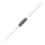
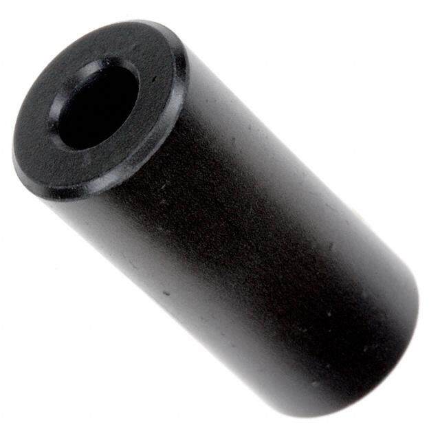
| 描述 | VHF-CHOKE 100UH 1 A固定电感器 100uH 1.0A 0.65ohms |
| 产品分类 | |
| 品牌 | EPCOS |
| 产品手册 | |
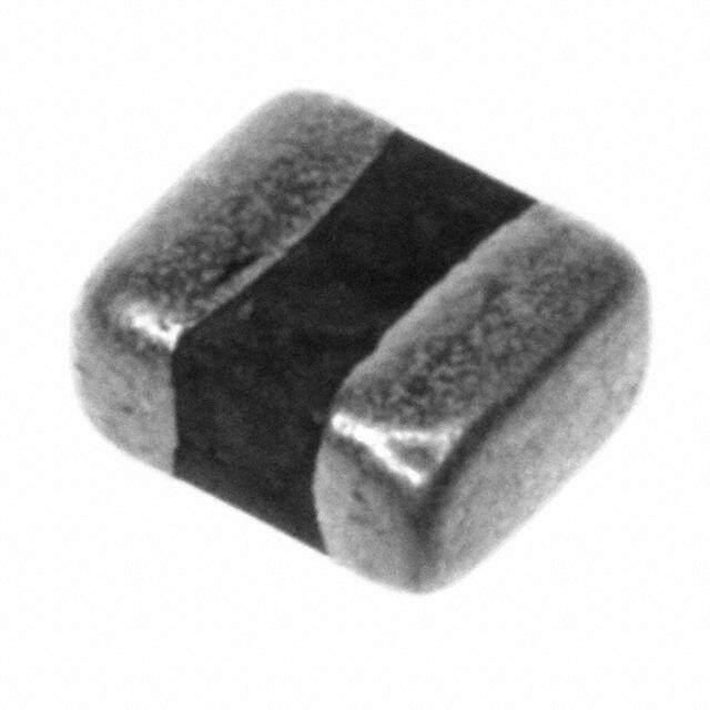
| 产品图片 |
|
| rohs | 符合RoHS无铅 / 符合限制有害物质指令(RoHS)规范要求 |
| 产品系列 | 固定电感器,EPCOS B82111EC25B82111E |
| 数据手册 | |
| 产品型号 | B82111EC25 |
| 不同频率时的Q值 | - |
| 产品种类 | 固定电感器 |
| 供应商器件封装 | - |
| 其它名称 | 495-5593-2 |
| 包装 | 带卷 (TR) |
| 商标 | EPCOS |
| 大小/尺寸 | 0.256" 直径 x 1.023" 长 (6.50mm x 26.00mm) |
| 安装类型 | 通孔 |
| 容差 | 20 % |
| 封装 | Reel |
| 封装/外壳 | 轴向 |
| 屏蔽 | 无屏蔽 |
| 工作温度 | - |
| 工厂包装数量 | 1000 |
| 最大直流电流 | 1 A |
| 最大直流电阻 | 650 mOhms |
| 材料-磁芯 | 铁氧体 |
| 标准包装 | 1,000 |
| 电感 | 100 uH |
| 电流-饱和值 | - |
| 端接类型 | Axial |
| 类型 | 绕线 |
| 自谐振频率 | 55 MHz |
| 零件号别名 | B82111E0000C025 |
| 频率-测试 | - |
| 频率-自谐振 | 55MHz |
| 额定电流 | 1A |
| 高度-安装(最大值) | - |


- 商务部:美国ITC正式对集成电路等产品启动337调查
- 曝三星4nm工艺存在良率问题 高通将骁龙8 Gen1或转产台积电
- 太阳诱电将投资9.5亿元在常州建新厂生产MLCC 预计2023年完工
- 英特尔发布欧洲新工厂建设计划 深化IDM 2.0 战略
- 台积电先进制程称霸业界 有大客户加持明年业绩稳了
- 达到5530亿美元!SIA预计今年全球半导体销售额将创下新高
- 英特尔拟将自动驾驶子公司Mobileye上市 估值或超500亿美元
- 三星加码芯片和SET,合并消费电子和移动部门,撤换高东真等 CEO
- 三星电子宣布重大人事变动 还合并消费电子和移动部门
- 海关总署:前11个月进口集成电路产品价值2.52万亿元 增长14.8%


PDF Datasheet 数据手册内容提取
Inductors VHF chokes Series/Type: B82111E Date: June 2012 aa~~íí~~==ppÜÜÉÉÉÉíí © EPCOS AG 2015. Reproduction, publication and dissemination of this publication, enclosures hereto and the information contained therein without EPCOS' prior express consent is prohibited. EPCOS AG is a TDK Group Company.
VHF chokes B82111E Rated voltage 500 V AC/DC Rated current 0.1 ... 6 A Rated inductance 7 ... 1200 µH Construction ■ Ferrite cylinder core ■ Winding: single-layer, enamel copper wire ■ Polyester insulating sleeve Features ■ High resonant frequency ■ Wide inductance range ■ Design complies with EN 60938 ■ Suitable for wave soldering ■ RoHS-compatible Applications ■ RF blocking and filtering ■ Interference suppression in small appliances ■ Decoupling in telecommunications and entertainment electronics Terminals ■ Central axial leads ■ Base material Cu ■ Hot-dip tinned with pure tin Marking L and I in clear text R R Delivery mode and packing unit ■ Taped and reeled ■ Packing unit: 1000 pcs./reel Please read Cautions and warnings and Important notes at the end of this document. 2 06/12
VHF chokes B82111E Dimensional drawing _ 73 1 9±0.5 26 max. ax. m 8 d 0. ø 30 min. *)10±0.5 IND0151-A *)10±0.5 x. 27.4 max. ma 2 1. Dimensions in mm *)Tolerance over 10 spacings ±2 mm IND0150-S-E Reel packing B82111E*C020, C029 5 2 3 97+1 109 max. IND0625-B B82111E*C021 … C028 5 1 0. ± 5 0. 30 _1 ø3 +1 3 0 6 3 6 2 1 3 1 ø ø ø Label 95+1 30 107 max. IND0451-4-E Dimensions in mm Please read Cautions and warnings and Important notes at the end of this document. 3 06/12
VHF chokes B82111E Technical data and measuring conditions Test voltage V 2500 V AC, 1 min test Rated inductance L Measured with LCR meter Agilent 4284A R or impedance analyzer Agilent 4294A Measuring frequency: L 10 H = 1 MHz R 10 H < L 1000 H = 100 kHz R L 1000 H = 10 kHz R Measuring voltage: 1 V Measuring temperature: +20 °C Inductance tolerance 20% Rated temperature T +60 °C R Rated current I Maximum permissible DC current at rated temperature R DC resistance R Measured at +20 C, tolerance 20%, typical values typ Resonance frequency f Measured with Agilent 4294A or 8753ES, +20 °C, res tolerance 30% Solderability (lead-free) Sn95.5Ag3.8Cu0.7: +(245 5) °C, (3 0.3) s Wetting of soldering area 90% (to IEC 60068-2-20, test Ta) Resistance to soldering heat +(260 5) °C, 10s (wave soldering) (to IEC 60068-2-20, test Tb) Tensile strength of leads 30 N (to IEC 60068-2-21, test Ua) Climatic category 55/125/56 (to IEC 60068-1) Storage conditions Mounted: –55 °C … +125 °C Packaged: –25 °C … +40 °C, 75% RH Mounting information When bending the leads, take care that the bending point is at least 3 mm apart from the face ends of the core and that the start-of-winding areas are not subjected to any mechanical stress. Please read Cautions and warnings and Important notes at the end of this document. 4 06/12
VHF chokes B82111E Characteristics and ordering codes I L R f Approx. Dimensions Ordering code R R typ res weight d max A H MHz g mm 0.1 1200 34 16 2.2 6.0 B82111E0000C029 0.2 680 14 19 2.2 6.0 B82111E0000C028 0.3 470 6.5 25 2.3 6.0 B82111E0000C027 0.5 220 2.6 32 2.3 6.5 B82111E0000C026 1 100 0.65 55 2.5 6.5 B82111E0000C025 1.5 56 0.30 70 2.7 6.5 B82111E0000C024 2 40 0.18 90 3.0 7.0 B82111E0000C023 3 22 0.07 110 3.3 7.0 B82111E0000C022 4 12 0.04 140 3.5 7.5 B82111E0000C021 6 7 0.02 180 3.6 7.5 B82111E0000C020 Impedance |Z| versus frequency f Current derating I /I op R measured with impedance analyzer Agilent versus ambient temperature T A 4294A or S-parameter network analyzer (rated temperature T = +60 °C) R Agilent 8753ES, typical values at +20 °C 1.2 IND0143-T-E 106 IND0152-S I Z| Ω CC002289 B82111E IoRp1.0 C027 C026 105 0.8 0.6 104 0.4 C025 C024 103 C023 0.2 C022 C021 C020 0 102 0 20 40 60 80 100 ˚C 140 106 107 108 Hz 109 T A f Please read Cautions and warnings and Important notes at the end of this document. 5 06/12
Cautions and warnings ■ Please note the recommendations in our Inductors data book (latest edition) and in the data sheets. – Particular attention should be paid to the derating curves given there. – The soldering conditions should also be observed. Temperatures quoted in relation to wave soldering refer to the pin, not the housing. ■ If the components are to be washed varnished it is necessary to check whether the washing varnish agent that is used has a negative effect on the wire insulation, any plastics that are used, or on glued joints. In particular, it is possible for washing varnish agent residues to have a negative effect in the long-term on wire insulation. Washing processes may damage the product due to the possible static or cyclic mechanical loads (e.g. ultrasonic cleaning). They may cause cracks to develop on the product and its parts, which might lead to reduced reliability or lifetime. ■ The following points must be observed if the components are potted in customer applications: – Many potting materials shrink as they harden. They therefore exert a pressure on the plastic housing or core. This pressure can have a deleterious effect on electrical properties, and in extreme cases can damage the core or plastic housing mechanically. – It is necessary to check whether the potting material used attacks or destroys the wire insulation, plastics or glue. – The effect of the potting material can change the high-frequency behaviour of the components. ■ Ferrites are sensitive to direct impact. This can cause the core material to flake, or lead to breakage of the core. ■ Even for customer-specific products, conclusive validation of the component in the circuit can only be carried out by the customer. Please read Cautions and warnings and Important notes at the end of this document. 6 06/12
Important notes The following applies to all products named in this publication: 1. Some parts of this publication contain statements about the suitability of our products for certain areas of application. These statements are based on our knowledge of typical requirements that are often placed on our products in the areas of application concerned. We nevertheless expressly point out that such statements cannot be regarded as binding statements about the suitability of our products for a particular customer application. As a rule, EPCOS is either unfamiliar with individual customer applications or less familiar with them than the customers themselves. For these reasons, it is always ultimately incumbent on the customer to check and decide whether an EPCOS product with the properties described in the product specification is suitable for use in a particular customer application. 2. We also point out that in individual cases, a malfunction of electronic components or failure before the end of their usual service life cannot be completely ruled out in the current state of the art, even if they are operated as specified. In customer applications requiring a very high level of operational safety and especially in customer applications in which the malfunction or failure of an electronic component could endanger human life or health (e.g. in accident prevention or life-saving systems), it must therefore be ensured by means of suitable design of the customer application or other action taken by the customer (e.g. installation of protective circuitry or redundancy) that no injury or damage is sustained by third parties in the event of malfunction or failure of an electronic component. 3. The warnings, cautions and product-specific notes must be observed. 4. In order to satisfy certain technical requirements, some of the products described in this publication may contain substances subject to restrictions in certain jurisdictions (e.g. because they are classed as hazardous). Useful information on this will be found in our Material Data Sheets on the Internet (www.epcos.com/material). Should you have any more detailed questions, please contact our sales offices. 5. We constantly strive to improve our products. Consequently, the products described in this publication may change from time to time. The same is true of the corresponding product specifications. Please check therefore to what extent product descriptions and specifications contained in this publication are still applicable before or when you place an order. We also reserve the right to discontinue production and delivery of products. Consequently, we cannot guarantee that all products named in this publication will always be available. The aforementioned does not apply in the case of individual agreements deviating from the foregoing for customer-specific products. 6. Unless otherwise agreed in individual contracts, all orders are subject to the current version of the “General Terms of Delivery for Products and Services in the Electrical Industry” published by the German Electrical and Electronics Industry Association (ZVEI). 7.The trade names EPCOS, BAOKE, Alu-X, CeraDiode, CeraLink, CSMP, CSSP, CTVS, DeltaCap, DigiSiMic, DSSP, FilterCap, FormFit, MiniBlue, MiniCell, MKD, MKK, MLSC, MotorCap, PCC, PhaseCap, PhaseCube, PhaseMod, PhiCap, SIFERRIT, SIFI, SIKOREL, SilverCap, SIMDAD, SiMic, SIMID, SineFormer, SIOV, SIP5D, SIP5K, ThermoFuse, WindCap are trademarks registered or pending in Europe and in other countries. Further information will be found on the Internet at www.epcos.com/trademarks. 7 06/12
Mouser Electronics Authorized Distributor Click to View Pricing, Inventory, Delivery & Lifecycle Information: E PCOS / TDK: B82111EC20 B82111EC21 B82111EC22 B82111EC23 B82111EC24 B82111EC25 B82111EC26 B82111EC27 B82111EC28 B82111EC29 B82111E0000C029 B82111E0000C028 B82111E0000C026 B82111E0000C021 B82111E0000C027 B82111E0000C024