ICGOO在线商城 > 开发板,套件,编程器 > 评估板 - 嵌入式 - MCU,DSP > AVR-H128-CAN
 Datasheet下载
- 型号: AVR-H128-CAN
- 制造商: Olimex Ltd.
- 库位|库存: xxxx|xxxx
- 要求:
| 数量阶梯 | 香港交货 | 国内含税 |
| +xxxx | $xxxx | ¥xxxx |
查看当月历史价格
查看今年历史价格
AVR-H128-CAN产品简介:
ICGOO电子元器件商城为您提供AVR-H128-CAN由Olimex Ltd.设计生产,在icgoo商城现货销售,并且可以通过原厂、代理商等渠道进行代购。 AVR-H128-CAN价格参考¥166.33-¥166.33。Olimex Ltd.AVR-H128-CAN封装/规格:评估板 - 嵌入式 - MCU,DSP, AT90CAN128-16AU AVR® MCU 8-Bit AVR Embedded Evaluation Board。您可以下载AVR-H128-CAN参考资料、Datasheet数据手册功能说明书,资料中有AVR-H128-CAN 详细功能的应用电路图电压和使用方法及教程。
Olimex LTD 的评估板型号 AVR-H128-CAN 属于嵌入式 MCU/DSP 类别,基于 Atmel(现为 Microchip)的 AVR 系列微控制器。该评估板主要应用场景包括以下几类:

 1. 工业自动化
   - CAN 总线通信:AVR-H128-CAN 配备 CAN 接口,适合用于工业设备中的节点通信,例如传感器数据采集、电机控制和分布式控制系统。
   - 实时控制:利用 AVR 微控制器的高性能处理能力,实现对工业设备的精确控制,如温度、压力和流量的实时监控。

 2. 汽车电子
   - 车载网络:CAN 协议广泛应用于汽车电子系统中,AVR-H128-CAN 可用于开发车灯控制、门窗控制、座椅调节等模块。
   - 诊断工具:作为 CAN 总线的接口设备,可用于读取和分析车辆 OBD(车载诊断系统)数据。

 3. 物联网 (IoT)
   - 传感器网关:结合 CAN 总线和 MCU 的处理能力,可作为传感器数据的汇聚点,将信息传输到云端或本地控制系统。
   - 低功耗设备:AVR 微控制器以低功耗著称,适合电池供电的 IoT 设备,如环境监测节点。

 4. 机器人技术
   - 运动控制:通过 CAN 总线连接多个伺服电机控制器,实现多轴机器人的协同动作。
   - 数据采集与处理:利用 MCU 的 ADC 和 GPIO 功能,采集传感器数据并进行初步处理。

 5. 教育与研发
   - 学习平台:适用于大学或培训机构的教学实验,帮助学生了解 CAN 总线协议、嵌入式系统设计和 MCU 编程。
   - 原型开发:工程师可以使用此评估板快速验证概念,开发基于 AVR 和 CAN 的产品原型。

 6. 智能家居
   - 设备互联:通过 CAN 总线连接多个智能设备(如灯光、窗帘、空调),构建可靠的局域网络。
   - 安全系统:用于门禁控制、报警系统等需要高可靠性和实时响应的应用。

 总结
AVR-H128-CAN 评估板凭借其强大的 AVR 微控制器和 CAN 总线功能,适合多种嵌入式应用场景,特别是在需要实时通信和控制的领域。它为开发者提供了灵活的硬件平台,支持从教育到工业的各种应用需求。
| 参数 | 数值 |
| 产品目录 | 编程器,开发系统嵌入式解决方案 |
| 描述 | AVR CAN HEADER BOARD开发板和工具包 - AVR HDR BRD FOR AT90CAN128-16AU |
| 产品分类 | 评估板 - 嵌入式 - MCU, DSP工程工具 |
| 品牌 | Olimex Ltd.Olimex LTD |
| 产品手册 | |
| 产品图片 |
|
| rohs | 符合RoHS无铅 / 符合限制有害物质指令(RoHS)规范要求 |
| 产品系列 | 嵌入式开发工具,嵌入式处理器开发套件,开发板和工具包 - AVR,Olimex Ltd. AVR-H128-CANAVR® |
| 数据手册 | |
| 产品型号 | AVR-H128-CANAVR-H128-CAN |
| 产品 | Development Boards |
| 产品种类 | 开发板和工具包 - AVR |
| 其它名称 | 1188-1010 |
| 内容 | 板 |
| 商标 | Olimex Ltd. |
| 安装类型 | 固定 |
| 尺寸 | 47 mm x 47 mm |
| 工作电源电压 | 5 V |
| 工具用于评估 | AT90CAN128 |
| 平台 | - |
| 接口类型 | ICSP, JTAG |
| 操作系统 | - |
| 数据总线宽度 | 8 bit |
| 板类型 | 评估平台 |
| 标准包装 | 1 |
| 核心 | AVR8 |
| 核心处理器 | AVR |
| 用于 | AT90 |
| 类型 | MCU 8-位 |
| 设计资源 | |
| 配套使用产品/相关产品 | AT90CAN128-16AU |


- 商务部:美国ITC正式对集成电路等产品启动337调查
- 曝三星4nm工艺存在良率问题 高通将骁龙8 Gen1或转产台积电
- 太阳诱电将投资9.5亿元在常州建新厂生产MLCC 预计2023年完工
- 英特尔发布欧洲新工厂建设计划 深化IDM 2.0 战略
- 台积电先进制程称霸业界 有大客户加持明年业绩稳了
- 达到5530亿美元!SIA预计今年全球半导体销售额将创下新高
- 英特尔拟将自动驾驶子公司Mobileye上市 估值或超500亿美元
- 三星加码芯片和SET,合并消费电子和移动部门,撤换高东真等 CEO
- 三星电子宣布重大人事变动 还合并消费电子和移动部门
- 海关总署:前11个月进口集成电路产品价值2.52万亿元 增长14.8%


PDF Datasheet 数据手册内容提取
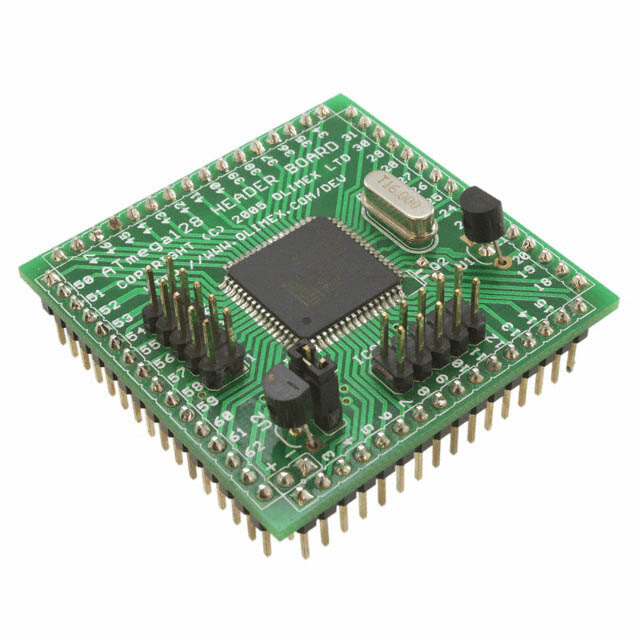
AVR- H128-CAN development board Users Manual All boards produced by Olimex are ROHS compliant Rev.A, January 2005 Copyright(c) 2009, OLIMEX Ltd, All rights reserved Page1
INTRODUCTION AVR-H128-CAN is inexpensive way to develop and prototype circuits with AT90CAN128 without need to deal with SMD soldering. All microcontroller pins are available on extension header with 0.1" and power supply, oscillators, ICSP, JTAG are wired, so all you need to do is to connect your additional components to the AVR ports, as the step is 0.1" these headers perfectly fit the prototype sea of pad boards with 0.1" step. BOARD FEATURES – AT90CAN128-16AU microcontroller with 128KB Flash, 4KB RAM, 4KB EEPROM, CAN controller – ICSP 5x2 pin connector for in-circuit programming with AVR-PG1 or AVR-PG2 or STK500 compatible programmer – JTAG 5x2 pin connector for in-circuit debugging with AVR-JTAG-L or AVR- JTAG-USB – 16MHz scillator circuit – 32768 Hz oscillator circuit – Reset IC ZM33064 – +5V voltage regulator LM78L05 – power supply filtering capacitors – extension pin headers for each uC pin – FR-4, 1.5 mm (0,062"), green soldermask, white silkscreen component print – dimensions 47x47 mm (1.85x1.85") ELECTROSTATIC WARNING The AVR-H128-CAN board is shipped in protective anti-static packaging. The board must not be subject to high electrostatic potentials. General practice for working with static sensitive devices should be applied when working with this board. BOARD USE REQUIREMENTS Cables: The cable you will need depends on the programmer/debugger you use. If you use AVR-JTAG or AVR-PG1 you will need RS232, if you use AVR-USB-JTAG or AVR-ISP500/TINY/ISO you will need 1.8 m A-B USB cable, if you use AVR- PG2, you will need LPT cable. Hardware: One of OLIMEX Programmers/Debuggers – AVR-JTAG, AVR-USB- JTAG, AVR-ISP500, AVR-ISP500-TINY, AVR-ISP500-ISO, AVR-PG1, AVR-PG2. Software: AVR C compiler. Page2
PROCESSOR FEATURES AVR-H128-CAN board use High-performance, Low-power AVR® 8-bit Microcontroller – AT90CAN128 from Atmel Corporation with these features: – Advanced RISC Architecture – 133 Powerful Instructions – Most Single Clock Cycle Execution – 32 x 8 General Purpose Working Registers + Peripheral Control Registers – Fully Static Operation – Up to 16 MIPS Throughput at 16 MHz – On-chip 2-cycle Multiplier – Non volatile Program and Data Memories – 128K Bytes of In-System Reprogrammable Flash – Endurance: 10,000 Write/Erase Cycles – Optional Boot Code Section with Independent Lock Bits – Selectable Boot Size: 1K Bytes, 2K Bytes, 4K Bytes or 8K Bytes – In-System Programming by On-Chip Boot Program (CAN, UART, ...) – True Read-While-Write Operation – 4K Bytes EEPROM (Endurance: 100,000 Write/Erase Cycles) – 4K Bytes Internal SRAM – Up to 64K Bytes Optional External Memory Space – Programming Lock for Software Security – JTAG (IEEE std. 1149.1 Compliant) Interface – Boundary-scan Capabilities According to the JTAG Standard – Programming Flash (Hardware ISP), EEPROM, Lock & Fuse Bits – Extensive On-chip Debug Support – CAN Controller 2.0A & 2.0B - ISO 16845 Certified – 15 Full Message Objects with Separate Identifier Tags and Masks – Transmit, Receive, Automatic Reply and Frame Buffer Receive Modes – 1Mbits/s Maximum Transfer Rate at 8 MHz – Time stamping, TTC & Listening Mode (Spying or Autobaud) – Peripheral Features – Programmable Watchdog Timer with On-chip Oscillator – 8-bit Synchronous Timer/Counter-0 – 10-bit Prescaler – External Event Counter – Output Compare or 8-bit PWM Output Page3
– 8-bit Asynchronous Timer/Counter-2 – 10-bit Prescaler – External Event Counter – Output Compare or 8-Bit PWM Output – 32Khz Oscillator for RTC Operation – Dual 16-bit Synchronous Timer/Counters-1 & 3 – 10-bit Prescaler – Input Capture with Noise Canceler – External Event Counter – 3-Output Compare or 16-Bit PWM Output – Output Compare Modulation – 8-channel, 10-bit SAR ADC – 8 Single-ended Channels – 7 Differential Channels – 2 Differential Channels With Programmable Gain at 1x, 10x, or 200x – On-chip Analog Comparator – Byte-oriented Two-wire Serial Interface – Dual Programmable Serial USART – Master/Slave SPI Serial Interface – Programming Flash (Hardware ISP) – Special Microcontroller Features – Power-on Reset and Programmable Brown-out Detection – Internal Calibrated RC Oscillator – 8 External Interrupt Sources – 5 Sleep Modes: Idle, ADC Noise Reduction, Power-save, Power-down & Standby – Software Selectable Clock Frequency – Global Pull-up Disable – Operating Voltages: 2.7 – 5.5V – Operating temperature: Industrial (-40°C to +85°C) – Maximum Frequency: 8 MHz at 2.7V, 16 MHz at 4.5V – 53 Programmable I/O Lines Page4
BLOCK DIAGRAM Page5
MEMORY MAP: Page6
Page7
SCHEMATIC EPWR D1 U2 +5V +5V +5V 1N4148 78L05 21 ICSP POWER 2 IN OUT PE0 1 2 1 C6 C7 C3 C4 3 4 GND RESET 5 6 R1 100n 100n 100n 100n PB1 7 8 PE1 9 10 4.7K +5V +5V JTAG U1 ZM33064 IC1 12 TCK 1 2 25 TDO 3 4 2VCC RESET 3 C1 RXETSAEL1T 20 RESET/ VCC TMS 5 6 RESET G1ND 16.0020M0pHFz/20pFQ1 2243 XXTTAALL12 TDI 79 810 C2 XTAL2 51 PA0 CON1 20pF pF TTOOSSCC12 1198 TTOOSSCC12 AAADDD012---PPPAAA012 5409 PPAA12 CON4 1 PEN 6 48 PA3 PA2 1 2 PE0 Q2 Hz/ PE0 2 RXD-PE0 AADD34--PPAA34 47 PA4 PA1 2 3456 PPPPEEEE1234 20pFC8 32KC920pFPPPPEEEE1234 4563 AAITNXCCTD+-4_-_-PPPPEEEE1432 AAADDD567---PPPAAA567 444654 PPPAAA567 +GPT5ADNV0ID 3456 7 PE5 PE5 7 INT5-PE5 A8-PC0 35 PC0 TDO 7 8 PE6 PE6 8 INT6-PE6 A9-PC1 36 PC1 TMS 8 9 PE7 PE7 9 INT7-PE7 A10-PC2 37 PC2 TCK 9 10 PB0 38 PC3 PF3 10 A11-PC3 11 PB1 PD0 25 PD0-INT0 A12-PC4 39 PC4 PF2 11 12 PB2 PD1 26 PD1-INT1 A13-PC5 40 PC5 PF1 12 13 PB3 PD2 27 PD2-INT2 A14-PC6 41 PC6 PF0 13 14 PB4 PD3 28 PD3-INT3 A15-PC7 42 PC7 AREF 14 15 PB5 PD4 29 PD4-IC1 GND 15 16 PB6 PD5 30 PD5 +5V 16 PD6 31 17 PB7 PD6-T1 OC2-PB7 PD7 32 16 PB6 CON2 PD7-T2 OC1B-PB6 15 PB5 CON3 OC1A-PB5 1 PB7 PF0 61 ADC0-PF0 OC0-PB4 14 PB4 WR 1 2 TOSC2 PF1 60 ADC1-PF1 MISO-PB3 13 PB3 RD 2 3 TOSC1 PF2 59 ADC2-PF2 MOSI-PB2 12 PB2 PC0 3 4 RESET PF3 58 ADC3-PF3 SCK-PB1 11 PB1 PC1 4 56 G+N5DV TTCMKS 5576 AADDCC45--PPFF45 SS-PB0 10 PB0 +5V PPCC23 56 7 XTAL2 TDO 55 ADC6-PF6 PC4 7 8 XTAL1 +5V TDI 54 ADC7-PF7 ALE 43 ALE PC5 8 9 PD0 34 RD R2 PC6 9 RD/ 10 PD1 +5V 64 AVCC WR/ 33 WR 1K PC7 10 11 PD2 1 PEN ALE 11 12 PD3 C5 AREF 62 PEN/ PA7 12 AVREF 13 PD4 PA6 13 100n 14 PD5 GND 63 PA5 14 AGND 15 PD6 GND PA4 15 16 PD7 ATMEGA128CAN 5322 PA3 16 AVR-H128-CAN Rev. A COPYRIGHT(C), 2005 http://www.olimex.com/dev Page8
BOARD LAYOUT Page9
POWER SUPPLY CIRCUIT The board is power supplied from POWER connector pin 1 and pin 2 with 9-12 V DC. RESET CIRCUIT AVR-H128-CAN reset circuit includes pin 6 of JTAG connector, pin 5 of ICSP connector, Extension connector CON2 – pin 4 and AT90CAN128 pin 20. CLOCK CIRCUIT Quartz crystal 16MHz is connected to AT90CAN128 pin 23 (XTAL2) and pin 24 (XTAL1). Quartz crystal 32kHz is connected to AT90CAN128 pin 18 (TOSC2) and pin 19 (TOSC1). JUMPER DESCRIPTION EPWR Enable target power supply. Page10
CONNECTOR DESCRIPTIONS JTAG Pin # Signal Name 1 TCK 2 GND 3 TDO 4 +5V 5 TMS 6 RESET 7 +5V 8 NC 9 TDI 10 GND ICSP Pin # Signal Name 1 PE0 2 +5V 3 NC 4 GND 5 RESET 6 GND 7 PB1 8 GND 9 PE1 10 GND Page11
CON1 Pin # Signal Name Pin # Signal Name 1 PEN 2 PE0 3 PE1 4 PE2 5 PE3 6 PE4 7 PE5 8 PE6 9 PE7 10 PB0 11 PB1 12 PB2 13 PB3 14 PB4 15 PB5 16 PB6 CON2 Pin # Signal Name Pin # Signal Name 17 PB7 18 TOSC2 19 TOSC1 20 RESET 21 +5V 22 GND 23 XTAL2 24 XTAL1 25 PD0 26 PD1 27 PD2 28 PD3 29 PD4 30 PD5 31 PD6 32 PD7 Page12
CON3 Pin # Signal Name Pin # Signal Name 33 WR 34 RD 35 PC0 36 PC1 37 PC2 38 PC3 39 PC4 40 PC5 41 PC6 42 PC7 43 ALE 44 PA7 45 PA6 46 PA5 47 PA4 48 PA3 CON4 Pin # Signal Name Pin # Signal Name 49 PA2 50 PA1 51 PA0 52 +5V 53 GND 54 TDI 55 TDO 56 TMS 57 TCK 58 PF3 59 PF2 60 PF1 61 PF0 62 AREF 63 GND 64 +5V POWER CONNECTOR Pin # Signal Name 1 (+) VCC 2 (-) GND Page13
MECHANICAL DIMENSIONS Page14
AVAILABLE DEMO SOFTWARE – Blinking LED C source for WinAVR – UART initialization C source for WinAVR Page15
ORDER CODE AVR-H128-CAN – assembled and tested board, includes AT90CAN128-16 microcontroller. How to order? You can order to us directly or by any of our distributors. Check our web www.olimex.com/dev for more info. Revision history: REV.A - create January 2005 Page16
Disclaimer: © 2009 Olimex Ltd. All rights reserved. Olimex®, logo and combinations thereof, are registered trademarks of Olimex Ltd. Other terms and product names may be trademarks of others. The information in this document is provided in connection with Olimex products. No license, express or implied or otherwise, to any intellectual property right is granted by this document or in connection with the sale of Olimex products. Neither the whole nor any part of the information contained in or the product described in this document may be adapted or reproduced in any material from except with the prior written permission of the copyright holder. The product described in this document is subject to continuous development and improvements. All particulars of the product and its use contained in this document are given by OLIMEX in good faith. However all warranties implied or expressed including but not limited to implied warranties of merchantability or fitness for purpose are excluded. This document is intended only to assist the reader in the use of the product. OLIMEX Ltd. shall not be liable for any loss or damage arising from the use of any information in this document or any error or omission in such information or any incorrect use of the product. Page17