ICGOO在线商城 > 射频/IF 和 RFID > 衰减器 > ATN3590-02
 Datasheet下载
- 型号: ATN3590-02
- 制造商: SKYWORKS
- 库位|库存: xxxx|xxxx
- 要求:
| 数量阶梯 | 香港交货 | 国内含税 |
| +xxxx | $xxxx | ¥xxxx |
查看当月历史价格
查看今年历史价格
ATN3590-02产品简介:
ICGOO电子元器件商城为您提供ATN3590-02由SKYWORKS设计生产,在icgoo商城现货销售,并且可以通过原厂、代理商等渠道进行代购。 ATN3590-02价格参考¥19.76-¥32.67。SKYWORKSATN3590-02封装/规格:衰减器, RF Attenuator 2dB ±0.2dB 0Hz ~ 40GHz 50 Ohms 2W Die。您可以下载ATN3590-02参考资料、Datasheet数据手册功能说明书,资料中有ATN3590-02 详细功能的应用电路图电压和使用方法及教程。
Skyworks Solutions Inc. 的 ATN3590-02 是一款高性能的射频(RF)衰减器,广泛应用于通信系统、测试设备和无线网络等领域。以下是该型号的主要应用场景及特点:

 1. 无线通信
   - 基站与中继设备:ATN3590-02 可用于调节信号强度,确保基站与终端设备之间的通信质量稳定。
   - 蜂窝网络优化:在蜂窝网络中,衰减器用于平衡不同路径的信号强度,避免过强或过弱的信号干扰。

 2. 测试与测量
   - 信号源校准:在测试设备中,衰减器用于调整输入信号电平,以匹配测试仪器的动态范围。
   - 实验室环境模拟:通过精确控制信号衰减量,模拟真实场景中的信号传播损耗。

 3. 卫星通信
   - 地面站设备:在卫星通信系统中,衰减器用于调节上行链路和下行链路的信号功率,确保信号传输的稳定性。
   - 天线校准:用于校准天线增益,优化信号接收和发射性能。

 4. 雷达系统
   - 信号处理:在雷达系统中,衰减器用于控制回波信号的强度,以便更好地进行目标检测和距离测量。
   - 抗干扰设计:通过调节信号电平,减少外部干扰对雷达性能的影响。

 5. 物联网(IoT)与短距离通信
   - Wi-Fi 和蓝牙模块:在 IoT 设备中,衰减器可用于优化信号覆盖范围,防止信号过强导致的干扰。
   - Zigbee 网络:在多节点网络中,衰减器帮助平衡各节点间的信号强度,提高通信可靠性。

 6. 军事与航空航天
   - 通信保密:在军事通信中,衰减器用于控制信号功率,防止敌方截获或干扰。
   - 导航系统:在 GPS 或其他导航系统中,衰减器用于优化信号接收灵敏度。

 特点总结
- 高精度衰减:ATN3590-02 提供稳定的衰减量,适用于对信号强度要求严格的场景。
- 宽频率范围:支持多种射频应用,覆盖从低频到高频的通信需求。
- 小型化设计:适合集成到紧凑型设备中,满足现代电子产品的轻量化需求。

综上所述,ATN3590-02 在各种射频系统中扮演着关键角色,能够有效提升信号处理的灵活性和可靠性。
| 参数 | 数值 |
| 产品目录 | |
| 描述 | ATTENUATOR PAD CHIP 2W 2DB |
| 产品分类 | RF 模具产品 |
| 品牌 | Skyworks Solutions Inc |
| 数据手册 | |
| 产品图片 |
|
| 产品型号 | ATN3590-02 |
| rohs | 无铅 / 符合限制有害物质指令(RoHS)规范要求 |
| 产品系列 | - |
| 产品培训模块 | http://www.digikey.cn/PTM/IndividualPTM.page?site=cn&lang=zhs&ptm=25107 |
| 产品目录页面 | |
| 其它名称 | 863-1149 |
| 功能 | 衰减器,2W,2dB |
| 标准包装 | 100 |


- 商务部:美国ITC正式对集成电路等产品启动337调查
- 曝三星4nm工艺存在良率问题 高通将骁龙8 Gen1或转产台积电
- 太阳诱电将投资9.5亿元在常州建新厂生产MLCC 预计2023年完工
- 英特尔发布欧洲新工厂建设计划 深化IDM 2.0 战略
- 台积电先进制程称霸业界 有大客户加持明年业绩稳了
- 达到5530亿美元!SIA预计今年全球半导体销售额将创下新高
- 英特尔拟将自动驾驶子公司Mobileye上市 估值或超500亿美元
- 三星加码芯片和SET,合并消费电子和移动部门,撤换高东真等 CEO
- 三星电子宣布重大人事变动 还合并消费电子和移动部门
- 海关总署:前11个月进口集成电路产品价值2.52万亿元 增长14.8%


PDF Datasheet 数据手册内容提取
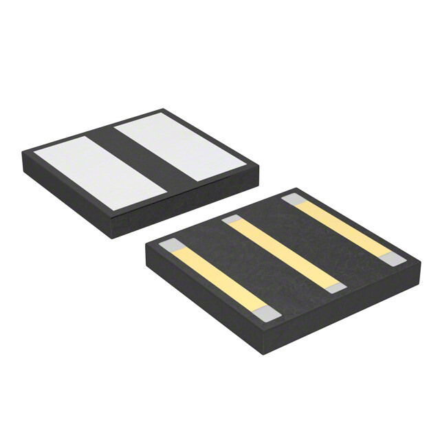
DATA SHEET ATN3590 Series: Fixed Attenuators Applications Level adjustment in radios, radars, EW/ECM equipment, and test instruments Features Fixed value, absorptive devices Available attenuation values range from 0 to 10 dB (in 1 dB steps), and 12, 15, 20, and 30 dB Suitable for use to 40 GHz or higher Excellent return loss: 30 dB, typical Out Enhanced power handling: 2 W Back Side Back Side Skyworks GreenTM products are compliant with all applicable legislation and are halogen-free. For additional information, refer to Skyworks In Definition of GreenTM, document number SQ04–0074. Schematic Figure 1. Typical Attenuator Die and Circuit Description The ATN3590 family of fixed resistive attenuators are integrated circuits comprising thin film resistors and through-die vias that provide excellent attenuation flatness from low frequency to 40 GHz or higher. These attenuators are available from 0 to 30 dB (see Table 2). The ATN3590 attenuator family is optimized for surface mounting on co-planar waveguide or microstrip printed circuit boards. Bond wires or ribbons are used to connect the input and output ports of the attenuators to the external circuit transmission lines. Connection to ground is accomplished by through-die vias to the die backside metallization. The dice are attached using eutectic solder or conductive epoxy and can operate over a temperature range of –65 C to 150 C. The absolute maximum ratings for the ATN3590 attenuators are provided in Table 1, and the electrical specifications are shown in Table 2. Typical performance characteristics are illustrated in Figures 2 through 8. Skyworks Solutions, Inc. • Phone [781] 376-3000 • Fax [781] 376-3100 • sales@skyworksinc.com • www.skyworksinc.com 200842E • Skyworks Proprietary Information • Products and Product Information are Subject to Change Without Notice • May 6, 2016 1
DATA SHEET • ATN3590 SERIES FIXED ATTENUATORS Table 1. ATN3590 Series Absolute Maximum Ratings1 Parameter Symbol Minimum Typical Maximum Units Input power PIN 2 W Power dissipation @ 25 °C PDIS 2 W Operating temperature TOP –55 +150 C Storage temperature TSTG –55 +150 C 1 Exposure to maximum rating conditions for extended periods may reduce device reliability. There is no damage to device with only one parameter set at the limit and all other parameters set at or below their nominal value. Exceeding any of the limits listed here may result in permanent damage to the device. ESD HANDLING: Although this device is designed to be as robust as possible, electrostatic discharge (ESD) can damage this device. This device must be protected at all times from ESD when handling or transporting. Static charges may easily produce potentials of several kilovolts on the human body or equipment, which can discharge without detection. Industry- standard ESD handling precautions should be used at all times. Table 2. ATN3590Series Electrical Specifications1 (TOP = +25 C, Characteristic Impedance [ZO] = 50 Ω, Unless Otherwise Noted) Attenuation Attenuation Attenuation Attenuation Attenuation Flatness Flatness Flatness Flatness Min. Return Min. Return Min. Return Min. Return Tolerance (Note 2) (Note 2) (Note 2) (Note 2) Loss Loss Loss Loss Attenuation @ DC DC–12 GHz 12–26 GHz 26–33 GHz 33–40 GHz DC–12 GHz 12–26 GHz 26–33 GHz 33–40 GHz Part Number (dB) (dB) (dB) (dB) (dB) (dB) (dB) (dB) (dB) (dB) ATN3590-00 0 0.25 ±0.15 ±0.15 ±0.20 ±0.20 28 24 20 16 ATN3590-01 1 ±0.20 ±0.15 ±0.15 ±0.20 ±0.20 28 24 20 16 ATN3590-02 2 ±0.20 ±0.15 ±0.15 ±0.20 ±0.20 28 24 20 16 ATN3590-03 3 ±0.20 ±0.15 ±0.15 ±0.20 ±0.20 28 24 20 16 ATN3590-04 4 ±0.20 ±0.15 ±0.15 ±0.20 ±0.20 28 24 20 16 ATN3590-05 5 ±0.20 ±0.15 ±0.15 ±0.20 ±0.20 28 24 20 16 ATN3590-06 6 ±0.40 ±0.15 ±0.15 ±0.20 ±0.20 28 24 20 16 ATN3590-07 7 ±0.40 ±0.15 ±0.15 ±0.20 ±0.20 28 24 20 16 ATN3590-08 8 ±0.40 ±0.15 ±0.15 ±0.20 ±0.20 28 24 20 16 ATN3590-09 9 ±0.40 ±0.20 ±0.20 ±0.25 ±0.30 28 24 20 16 ATN3590-10 10 ±0.40 ±0.20 ±0.20 ±0.25 ±0.50 28 24 20 16 ATN3590-12 12 ±0.40 ±0.20 ±0.20 ±0.30 ±0.50 28 24 20 16 ATN3590-15 15 ±0.40 ±0.20 ±0.20 ±0.50 ±0.75 28 24 20 16 ATN3590-20 20 ±1.0 ±0.20 ±0.20 ±0.75 ±1.00 28 24 20 16 ATN3590-30 30 ±1.0 ±0.20 ±0.25 ±0.75 ±2.50 28 24 20 16 1 Performance is guaranteed only under the conditions listed in this Table. 2 Flatness is defined as the maximum deviation from the mean value of attenuation over the specified frequency range. Skyworks Solutions, Inc. • Phone [781] 376-3000 • Fax [781] 376-3100 • sales@skyworksinc.com • www.skyworksinc.com 2 May 6, 2016 • Skyworks Proprietary Information • Products and Product Information are Subject to Change Without Notice • 200842E
DATA SHEET • ATN3590 SERIES FIXED ATTENUATORS Typical Performance Characteristics (TOP = +25 C, Characteristic Impedance [Zo] = 50 Ω, Unless Otherwise Noted. Data Gathered Using Ground-to-Signal-to-Ground Probes on Die) +2.0 –2.0 3 dB +1.5 0 dB 1 dB –2.5 4 dB +1.0 5 dB 2 dB +0.5 –3.0 0 Attenuation (dB) ––––0211....5050 Attenuation (dB) –––434...055 –2.5 –5.0 –3.0 –5.5 –3.5 –4.0 –6.0 0 5 10 15 20 25 30 35 40 0 5 10 15 20 25 30 35 40 Frequency (GHz) Frequency (GHz) Figure 2. Attenuation vs Frequency Figure 3. Attenuation vs Frequency (0 dB, 1 dB, and 2 dB Attenuators) (3 dB, 4 dB, and 5 dB Attenuators) –5.0 –8 6 dB 7 dB –5.5 8 dB –9 –6.0 –10 Attenuation (dB) –––767...055 Attenuation (dB) ––1121 –8.0 9 dB –8.5 –13 10 dB 12 dB –9.0 –14 0 5 10 15 20 25 30 35 40 0 5 10 15 20 25 30 35 40 Frequency (GHz) Frequency (GHz) Figure 4. Attenuation vs Frequency Figure 5. Attenuation vs Frequency (6 dB, 7 dB, and 8 dB Attenuators) (9 dB, 10 dB, and 12 dB Attenuators) –14 –16 –18 –20 B) d n ( –22 o uati –24 15 dB en 20 dB Att –26 30 dB –28 –30 –32 0 5 10 15 20 25 30 35 40 Frequency (GHz) Figure 6. Attenuation vs Frequency (15 dB, 20 dB, and 30 dB Attenuators) Skyworks Solutions, Inc. • Phone [781] 376-3000 • Fax [781] 376-3100 • sales@skyworksinc.com • www.skyworksinc.com 200842E • Skyworks Proprietary Information • Products and Product Information are Subject to Change Without Notice • May 6, 2016 3
DATA SHEET • ATN3590 SERIES FIXED ATTENUATORS 0 0 0 dB 1 dB 2 dB 3 dB 4 dB 5 dB 0 dB 1 dB 2 dB 3 dB 4 dB 5 dB –10 61 5d BdB 72 0d BdB 83 0d BdB 9 dB 10 dB 12 dB –10 61 5d BdB 72 0d BdB 83 0d BdB 9 dB 10 dB 12 dB –20 –20 B) B) d d s ( –30 n ( –30 put Return Los ––4500 mall Signal Gai ––4500 In –60 S –60 –70 –70 –80 –80 0 5 10 15 20 25 30 35 40 0 5 10 15 20 25 30 35 40 Frequency (GHz) Frequency (GHz) Figure 7. Input Return Loss vs Frequency Figure 8. Small Signal Gain vs Frequency Technical Description R3 The ATN3590 family of fixed attenuators comprises devices with R1 nominal attenuation values of 0 to 10 dB (in 1 dB steps), and 12, 15, 20, and 30 dB. These attenuators contain through-wafer vias R4 that connect the topside ground to the backside metallization of R2 each die. The devices with nominal attenuation values of 1 dB or greater are fabricated using thin film resistors deposited on GaAs Figure 9. Circuit Topology (1 to 5 dB Attenuators) substrates. The circuit topology is a simple tee structure that consists of two series resistors and a shunt resistance, which in this case is realized as a pair of shunt resistors connected to the R1 R4 node between the two series resistors (refer to Figures 9 and 10). The resistances of each of these resistors are selected to simultaneously produce the nominal attenuation with very good input and output return losses. R2 || R3 The attenuators with nominal attenuation values ≥6 dB contain a pair of cascaded tee sections (see Figure 11). The 0 dB attenuator, ATN3590-00, is a 50 Ω microstrip transmission line Figure 10. Simplified Circuit Topology (1 to 5 dB Attenuators) with identical foot print and bond pads to those of the other products in this family. R3 R5 Die Attachment and Signal Path Connection R1 Any of the ATN3590 family of attenuators should be mounted on the ground plane of a transmission medium. The die should be R4 R7 attached with conductive epoxy or a eutectic solder such as gold/tin (AuSn). R2 R6 For good high frequency performance, it is essential that there is no ground plane directly beneath the series signal path of the ATN3590. The backside metallization on the die is split into two Figure 11. Circuit Topology for Attenuators with Nominal regions along the sides of the die to accommodate this Attenuation ≥6 dB requirement. Skyworks Solutions, Inc. • Phone [781] 376-3000 • Fax [781] 376-3100 • sales@skyworksinc.com • www.skyworksinc.com 4 May 6, 2016 • Skyworks Proprietary Information • Products and Product Information are Subject to Change Without Notice • 200842E
DATA SHEET • ATN3590 SERIES FIXED ATTENUATORS The metallization on the circuit medium to which the attenuator is Package Dimensions to be mounted must also include the split in the ground The PCB layout footprint for the ATN3590 attenuators is shown in connections. It is recommended the gap between the ground pads Figure 13. Package dimensions are provided in Figure 14. on the circuit medium be 250 μm wide by 900 μm long. It is recommended that the signal paths be connected to the input/output bond pads on the attenuator with 0.25 mil thick x 3 Packaging mil wide (6.25 x 75 microns) Au ribbons, as shown in Figure 12. The standard mode of packaging for shipment of the ATN3590 Au wires can also be used. Attenuator Series is 100 pieces per GelPak™. Ø0.10 inch [0.25 mm] Vias 3 mil Au [0.08 mm] Ribbon 250 mil long [0.64 mm] (2 Places) Ground Input/Output Input/Output Ground 200842-012 Figure 12. Suggested Die Mount and Ribbon Attachment Skyworks Solutions, Inc. • Phone [781] 376-3000 • Fax [781] 376-3100 • sales@skyworksinc.com • www.skyworksinc.com 200842E • Skyworks Proprietary Information • Products and Product Information are Subject to Change Without Notice • May 6, 2016 5
DATA SHEET • ATN3590 SERIES FIXED ATTENUATORS 0.030 [0.76 mm] Ø0.10 [0.25 mm] 0.047 [1.19 mm] Vias 6X 4X 0.040 [1.02 mm] 2X 0.062 [1.57 mm] 0.140 [3.56 mm] 0.010 [0.25 mm] 0.070 [1.78 mm] 0.045 [1.13 mm] 0.030 [0.76 mm] Typ 0.062 [1.57 mm] 0.124 [3.15 mm] Notes: 1. Material: Alumina 99.6% 3. Unless otherwise specified: 4. Commercial published tolerances shall apply Dielectric constant 9.9 Dimensions are in inches to tubing, bar, plate, etc. All threads to Effective dielectric constant 6.8 Tolerances on finish: RMS 63 be Class 2A or Class 2B. Plated parts Transmission line width: 0.010” Angles ± 0.5° Fractions: ± 1/64 must fit gauges and meet specified tolerances Substrate thickness: 0.010” 4 place decimals: ±0.0005 after plating. Coplanar gap: 0.025” 3 place decimals: ±0.005 2 place decimals: ±0.02 2. Plating: Gold 100 to 150 micro-inches 200842-013 Figure 13. Suggested Land Pattern Skyworks Solutions, Inc. • Phone [781] 376-3000 • Fax [781] 376-3100 • sales@skyworksinc.com • www.skyworksinc.com 6 May 6, 2016 • Skyworks Proprietary Information • Products and Product Information are Subject to Change Without Notice • 200842E
DATA SHEET • ATN3590 SERIES FIXED ATTENUATORS 0.725 mm [0.0290] Additional Ground Contacts 0.110 mm [0.0044] x 0.075 mm [.003] (4 Places) Attenuator Value Ground Via to Backside 0.700 mm (8 Places) [0.0280] Input/Output Pad 0.110 mm [0.0044] x 0.075 mm [.003] Attenuator Value (2 Places) 0.100 mm 0.152 mm [0.0040] Low Inductance Ground Contact [0.0061] (Cu-Ti/Va-Au) Solder or Conductive Epoxy Attach Out Back Side Back Side In Schematic 200842-014 Notes: 1. All measurements in millimeters 2. All dimensions ± 0.025 mm [0.001 inch] Figure 14. ATN3590 Attenuator Series Die Dimensions Copyright © 2009, 2012-2013, 2016 Skyworks Solutions, Inc. All Rights Reserved. Information in this document is provided in connection with Skyworks Solutions, Inc. (“Skyworks”) products or services. These materials, including the information contained herein, are provided by Skyworks as a service to its customers and may be used for informational purposes only by the customer. Skyworks assumes no responsibility for errors or omissions in these materials or the information contained herein. Skyworks may change its documentation, products, services, specifications or product descriptions at any time, without notice. Skyworks makes no commitment to update the materials or information and shall have no responsibility whatsoever for conflicts, incompatibilities, or other difficulties arising from any future changes. No license, whether express, implied, by estoppel or otherwise, is granted to any intellectual property rights by this document. Skyworks assumes no liability for any materials, products or information provided hereunder, including the sale, distribution, reproduction or use of Skyworks products, information or materials, except as may be provided in Skyworks Terms and Conditions of Sale. THE MATERIALS, PRODUCTS AND INFORMATION ARE PROVIDED “AS IS” WITHOUT WARRANTY OF ANY KIND, WHETHER EXPRESS, IMPLIED, STATUTORY, OR OTHERWISE, INCLUDING FITNESS FOR A PARTICULAR PURPOSE OR USE, MERCHANTABILITY, PERFORMANCE, QUALITY OR NON-INFRINGEMENT OF ANY INTELLECTUAL PROPERTY RIGHT; ALL SUCH WARRANTIES ARE HEREBY EXPRESSLY DISCLAIMED. SKYWORKS DOES NOT WARRANT THE ACCURACY OR COMPLETENESS OF THE INFORMATION, TEXT, GRAPHICS OR OTHER ITEMS CONTAINED WITHIN THESE MATERIALS. SKYWORKS SHALL NOT BE LIABLE FOR ANY DAMAGES, INCLUDING BUT NOT LIMITED TO ANY SPECIAL, INDIRECT, INCIDENTAL, STATUTORY, OR CONSEQUENTIAL DAMAGES, INCLUDING WITHOUT LIMITATION, LOST REVENUES OR LOST PROFITS THAT MAY RESULT FROM THE USE OF THE MATERIALS OR INFORMATION, WHETHER OR NOT THE RECIPIENT OF MATERIALS HAS BEEN ADVISED OF THE POSSIBILITY OF SUCH DAMAGE. Skyworks products are not intended for use in medical, lifesaving or life-sustaining applications, or other equipment in which the failure of the Skyworks products could lead to personal injury, death, physical or environmental damage. Skyworks customers using or selling Skyworks products for use in such applications do so at their own risk and agree to fully indemnify Skyworks for any damages resulting from such improper use or sale. Customers are responsible for their products and applications using Skyworks products, which may deviate from published specifications as a result of design defects, errors, or operation of products outside of published parameters or design specifications. Customers should include design and operating safeguards to minimize these and other risks. Skyworks assumes no liability for applications assistance, customer product design, or damage to any equipment resulting from the use of Skyworks products outside of stated published specifications or parameters. Skyworks and the Skyworks symbol are trademarks or registered trademarks of Skyworks Solutions, Inc., in the United States and other countries. Third-party brands and names are for identification purposes only, and are the property of their respective owners. Additional information, including relevant terms and conditions, posted at www.skyworksinc.com, are incorporated by reference. Skyworks Solutions, Inc. • Phone [781] 376-3000 • Fax [781] 376-3100 • sales@skyworksinc.com • www.skyworksinc.com 200842E • Skyworks Proprietary Information • Products and Product Information are Subject to Change Without Notice • May 6, 2016 7