 Datasheet下载
- 型号: AD9963BCPZ
- 制造商: Analog
- 库位|库存: xxxx|xxxx
- 要求:
| 数量阶梯 | 香港交货 | 国内含税 |
| +xxxx | $xxxx | ¥xxxx |
查看当月历史价格
查看今年历史价格
AD9963BCPZ产品简介:
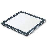
ICGOO电子元器件商城为您提供AD9963BCPZ由Analog设计生产,在icgoo商城现货销售,并且可以通过原厂、代理商等渠道进行代购。 AD9963BCPZ价格参考。AnalogAD9963BCPZ封装/规格:专用 IC, Broadband Front-End IC Wireless Networking 72-LFCSP-VQ (10x10)。您可以下载AD9963BCPZ参考资料、Datasheet数据手册功能说明书,资料中有AD9963BCPZ 详细功能的应用电路图电压和使用方法及教程。
AD9963BCPZ是由Analog Devices Inc.(亚德诺半导体公司)生产的一款专用集成电路(IC),主要用于消费类电子设备中的音频处理应用。该器件是一款高集成度的音频编解码器,结合了多种功能,以支持高质量的音频输入和输出。

 应用场景:

1. 便携式音频设备:
   AD9963BCPZ广泛应用于便携式音频设备中,如MP3播放器、便携式媒体播放器(PMP)、智能手机和平板电脑等。它能够提供高质量的音频编解码功能,支持多种音频格式的编码和解码,确保用户在移动设备上享受清晰、逼真的音质。

2. 语音识别与增强:
   该芯片内置先进的语音处理算法,可以用于语音识别系统和语音增强应用。它能够有效减少背景噪音,提高语音信号的质量,适用于智能音箱、语音助手等需要高精度语音输入的设备。

3. 智能家居设备:
   在智能家居设备中,AD9963BCPZ可以用于实现高质量的音频传输和处理。例如,智能音箱、智能门铃等设备可以通过该芯片实现清晰的语音交互和音乐播放功能。

4. 车载娱乐系统:
   AD9963BCPZ也适用于汽车音响系统和车载娱乐设备。它可以提供高质量的音频处理能力,支持多声道音频输出,提升车内音频体验。此外,它还具有低功耗特性,适合长时间运行的车载环境。

5. 可穿戴设备:
   随着可穿戴设备市场的快速发展,AD9963BCPZ也被应用于智能手表、健康监测设备等产品中。它的小尺寸和低功耗设计使得其非常适合这些对体积和电池寿命有严格要求的设备。

6. 专业音频设备:
   在专业音频领域,如录音设备、混音器等,AD9963BCPZ可以提供高精度的音频处理能力,支持多种采样率和位深度,满足专业用户的高标准需求。

总之,AD9963BCPZ凭借其高性能、低功耗和高集成度的特点,在各种音频处理应用场景中表现出色,是现代消费电子和专业音频设备的理想选择。
| 参数 | 数值 |
| 产品目录 | |
| 描述 | IC DAC DUAL 16BIT 72LFCSP射频前端 10-/12-Bit Low Power Broadband MxFE |
| DevelopmentKit | AD9963-EBZ |
| 产品分类 | RFID IC集成电路 - IC |
| 品牌 | Analog Devices Inc |
| 产品手册 | |
| 产品图片 |
|
| rohs | 符合RoHS无铅 / 符合限制有害物质指令(RoHS)规范要求 |
| 产品系列 | RF集成电路,射频前端,Analog Devices AD9963BCPZ- |
| 数据手册 | |
| 产品型号 | AD9963BCPZ |
| RF类型 | - |
| 产品种类 | 射频前端 |
| 供应商器件封装 | 72-LFCSP-VQ(10x10) |
| 包装 | 托盘 |
| 商标 | Analog Devices |
| 噪声系数 | 68 dB |
| 封装 | Tray |
| 封装/外壳 | 72-VFQFN 裸露焊盘,CSP |
| 封装/箱体 | LFCSP EP |
| 工作电源电压 | 1.72 V to 3.63 V |
| 工作频率 | 170 MHz |
| 工厂包装数量 | 168 |
| 最大工作温度 | + 85 C |
| 最大数据速率 | 100 MSPs |
| 最小工作温度 | - 40 C |
| 标准包装 | 1 |
| 特性 | - |
| 类型 | RF Front End |
| 系列 | AD9963 |
| 视频文件 | http://www.digikey.cn/classic/video.aspx?PlayerID=1364138032001&width=640&height=505&videoID=2245193150001 |
| 频率 | - |


- 商务部:美国ITC正式对集成电路等产品启动337调查
- 曝三星4nm工艺存在良率问题 高通将骁龙8 Gen1或转产台积电
- 太阳诱电将投资9.5亿元在常州建新厂生产MLCC 预计2023年完工
- 英特尔发布欧洲新工厂建设计划 深化IDM 2.0 战略
- 台积电先进制程称霸业界 有大客户加持明年业绩稳了
- 达到5530亿美元!SIA预计今年全球半导体销售额将创下新高
- 英特尔拟将自动驾驶子公司Mobileye上市 估值或超500亿美元
- 三星加码芯片和SET,合并消费电子和移动部门,撤换高东真等 CEO
- 三星电子宣布重大人事变动 还合并消费电子和移动部门
- 海关总署:前11个月进口集成电路产品价值2.52万亿元 增长14.8%


PDF Datasheet 数据手册内容提取
10-/12-Bit, Low Power, Broadband MxFE Data Sheet AD9961/AD9963 FEATURES FUNCTIONAL BLOCK DIAGRAM Dual 10-bit/12-bit, 100 MSPS ADC AD9961/AD9963 TEMPERATURE SNR = 67 dB, f = 30.1 MHz SENSOR IN Dual 10-bit/12-bit, 170 MSPS DAC AUX AUXIN1 ADC ACLR = 74 dBc 5 channels of analog auxiliary input/output DLLFILT DCLLLOACNKD DAAUCX MUX AUXIO2 CLKP DISTRIBUTION Low power, <425 mW at maximum sample rates CLKN DAAUCX AUXIO3 Supports full and half-duplex data interfaces Small 72-lead LFCSP lead-free package INTERNAL APPLICATIONS TXCLK 12-BIT TXIP TXIQ/TXnRX LPF DAC TXIN Wireless infrastructure 1/2/4/8 Picocell, femtocell basestations TXD[11:0] 12-BIT TXQP DATA LPF DAC TXQN Medical instrumentation ASSEMBLER 1/2/4/8 TRXCLK Ultrasound AFE TRXIQ 12-BIT RXIP Portable instrumentation LPF ADC RXIN 1/2 Signal generators, signal analyzers 12-BIT RXQP GENERAL DESCRIPTION TRXD[11:0] LPF ADC RXQN 1/2 The AD9961/AD9963 are pin-compatible, 10-/12-bit, low RESET DAAUCX DAC12A power MxFE® converters that provide two ADC channels with SDIO SERIAL sample rates of 100 MSPS and two DAC channels with sample SCLK LPOOGRITC DAAUCX DAC12B CS rates to 170 MSPS. These converters are optimized for transmit REFERENCES LDO AND BIAS VREGs and receive signal paths of communication systems requiring low pcalnoodwc ke8ri×n a ginn dot pelortpiwoo nclaos.ts itTo. hnTe.h Tterh adeni gsrimetcaielt i ivinse t ceporafntahfci gehsua rpsa rabo lbveiy dfpoear sf 1lsea×xb,i lb2el× e2, × 4 ×, UXADCREF REFIO TXCML RXCML RXBIAS LDO_EN 08801-001 A decimating low-pass filter. Figure 1. PRODUCT HIGHLIGHTS The AD9961 and AD9963 have five auxiliary analog channels. Three are inputs to a 12-bit ADC. Two of these inputs can be 1. High Performance with Low Power Consumption. configured as outputs by enabling 10-bit DACs. The other The DACs operate on a single 1.8 V to 3.3 V supply. two channels are dedicated outputs from two independent Transmit path power consumption is <100 mW at 12-bit DACs. 170 MSPS. Receive path power consumption is <350 mW at 100 MSPS from 1.8 V supply. Sleep and power-down The high level of integrated functionality, small size, and low modes are provided for low power idle periods. power dissipation of the AD9961/AD9963 make them well- suited for portable and low power applications. 2. High Integration. The dual transmit and dual receive data converters, five channels of auxiliary data conversion and clock generation offer complete solutions for many modem designs. 3. Flexible Digital Interface. The interface mates seamlessly to most digital baseband processors. Rev. A Information furnished by Analog Devices is believed to be accurate and reliable. However, no responsibility is assumed by Analog Devices for its use, nor for any infringements of patents or other One Technology Way, P.O. Box 9106, Norwood, MA 02062-9106, U.S.A. rights of third parties that may result from its use. Specifications subject to change without notice. No license is granted by implication or otherwise under any patent or patent rights of Analog Devices. Tel: 781.329.4700 www.analog.com Trademarks and registered trademarks are the property of their respective owners. Fax: 781.461.3113 ©2010–2012 Analog Devices, Inc. All rights reserved.
AD9961/AD9963 Data Sheet TABLE OF CONTENTS Features .............................................................................................. 1 Transmit DAC Outputs ............................................................. 42 Device Clocking .............................................................................. 45 Applications ....................................................................................... 1 General Description ......................................................................... 1 Clock Distribution ..................................................................... 45 Driving the Clock Input ............................................................ 46 Functional Block Diagram .............................................................. 1 Product Highlights ........................................................................... 1 Clock Multiplication Using the DLL ....................................... 46 Revision History ............................................................................... 2 Configuring the Clock Doublers .............................................. 47 Digital Interfaces ............................................................................ 48 Specifications ..................................................................................... 3 Absolute Maximum Ratings ............................................................ 8 TRx Port Operation (Full-Duplex Mode) ............................... 48 Single ADC Mode ...................................................................... 48 Thermal Resistance ...................................................................... 8 ESD Caution .................................................................................. 8 Tx Port Operation (Full-Duplex Mode) ................................. 49 Half-Duplex Mode ..................................................................... 50 Pin Configurations and Function Descriptions ........................... 9 Typical Performance Characteristics ........................................... 13 Auxiliary Converters ...................................................................... 52 Terminology .................................................................................... 18 Auxiliary ADC ............................................................................ 52 Conversion Clock ....................................................................... 52 Theory of Operation ...................................................................... 19 Serial Control Port .......................................................................... 20 Auxiliary DACs........................................................................... 53 Power Supplies ................................................................................ 55 General Operation of Serial Control Port ............................... 20 Sub Serial Interface Communications ..................................... 21 Power Supply Configuration Examples ................................... 55 Power Dissipation....................................................................... 55 Configuration Registers ................................................................. 23 Configuration Register Bit Descriptions ................................. 24 Example Start-Up Sequences ........................................................ 58 Receive Path..................................................................................... 35 Configuring the DLL ................................................................. 58 Configuring the Clock Doublers (DDLL)............................... 58 Receive ADC Operation ............................................................ 35 Decimation Filter and Digital Offset ....................................... 36 Sensing temperature with the AUXADC ................................ 58 Outline Dimensions ....................................................................... 59 Transmit Path .................................................................................. 38 Interpolation Filters.................................................................... 38 Ordering Guide .......................................................................... 59 Transmit DAC Operation .......................................................... 40 REVISION HISTORY 8/12—Rev. 0 to Rev. A Changes to Table 15 ........................................................................ 24 Changes to Figure 65 ...................................................................... 45 Added DLL Duty Cycle Caution Section .................................... 46 Changes to Table 22 ........................................................................ 47 Changes to Figure 93 and Power Supply Configuration Examples Section ............................................................................ 55 Added Example Start-Up Sequences Section ............................. 58 Updated Outline Dimensions ....................................................... 59 7/10—Revision 0: Initial Version Rev. A | Page 2 of 60
Data Sheet AD9961/AD9963 SPECIFICATIONS T to T , RX33V = TXVDD = CLK33V = DRVDD = AUX33V = 3.3 V. All LDOs enabled, I = 2 mA, DAC sample rate = 125 MSPS. No MIN MAX OUTFS interpolation, unless otherwise noted. Table 1. Tx Path Specifications AD9961 AD9963 Parameter Min Typ Max Min Typ Max Unit TxDAC DC CHARACTERISTICS Resolution 10 12 Bits Differential Nonlinearity 0.1 0.3 LSB Gain Variation (Internal Reference) −10 0.4 +10 −10 0.4 +10 %FSR Gain Matching −2.4 0.4 +2.4 −2.4 0.4 +2.4 %FSR Offset Error −0.03 +0.03 −0.03 +0.03 %FSR Full-Scale Output Current (Default Setting) 2.0 2.0 mA Output Compliance Range TXVDD = 3.3 V, V = 0 V −0.5 +1.0 −0.5 +1.0 V TXCML TXVDD = 3.3 V, V = 0.5 V +0.7 +1.7 +0.7 +1.7 V TXCML TXVDD = 1.8 V, V = 0 V −0.5 +0.8 −0.5 +0.8 V TXCML Offset Temperature Drift 0 0 ppm/°C Gain Temperature Drift (Internal Reference) ±40 ±40 ppm/°C Tx REFERENCE (DEFAULT REGISTER SETTINGS) Internal Reference Voltage (REFIO) 1.02 1.02 V Output Resistance 10 10 kΩ Temperature Drift ±25 ±25 ppm/°C Adjustment Range (TXVDD = 3 V) 0.8 1.2 0.8 1.2 V Adjustment Range (TXVDD = 1.8 V) 0.8 REFIO 0.8 REFIO V TxDAC AC CHARACTERISTICS Maximum Update Rate 175 175 MSPS Spurious-Free Dynamic Range f = 5 MHz 78 81 dBc OUT f = 20 MHz 68 70 dBc OUT Two-Tone Intermodulation Distortion f = 5 MHz, f = 6 MHz 85 89 dBc OUT1 OUT2 f = 20 MHz, f = 21 MHz 78 80 dBc OUT1 OUT2 Noise Spectral Density f = 5 MHz −140 −145 dBm/Hz OUT f = 20 MHz −136 −141 dBm/Hz OUT W-CDMA Adjacent Channel Leakage Ratio, 1 Carrier f = 122.88 MHz, f = 11 MHz 70 74 dBc DAC OUT Tx PATH DIGITAL FILTER INPUT RATES SRRC (8× Interpolation Mode) 21.875 21.875 MHz INT0 (4× Interpolation Mode) 43.75 43.75 MHz INT1 (2× Interpolation Mode 87.5 87.5 MHz Transmit DAC (1× Interpolation Mode) 175 175 MHz Rev. A | Page 3 of 60
AD9961/AD9963 Data Sheet T to T , RX33V = TXVDD = CLK33V = DRVDD = AUX33V = 3.3 V. All LDOs enabled, ADC sample rate = 100 MSPS. No MIN MAX decimation, unless otherwise noted. Table 2. Rx Path Specifications AD9961 AD9963 Parameter Min Typ Max Min Typ Max Unit Rx ADC DC CHARACTERISTICS Resolution 10 12 Bits Differential Nonlinearity 0.1 0.3 LSB Gain Error ±1 ±1 %FSR Offset Error ±0.5 ±0.5 %FSR Input Voltage Range 1.56 1.56 V p-p diff Input Capacitance 8 8 pF Rx ADC AC SPECIFICATIONS Maximum Sample Rate 100 100 MSPS Spurious Free Dynamic Range f = 10.1 MHz 77 77 dBc IN f = 70.1 MHz 75 73 dBc IN Two-Tone Intermodulation Distortion f = 10 MHz, f = 11 MHz 78 82 dBc IN1 IN2 f = 29 MHz, f = 32 MHz 76 80 dBc IN1 IN2 Signal-to-Noise Ratio f = 10.1 MHz 61 68 dBFS IN f = 30.1 MHz 60 67 dBFS IN f = 70.1 MHz 60 66 dBFS IN RXCML OUTPUTS Output Voltage 1.4 1.4 V Output Current 0.1 0.1 mA Rx DIGITAL FILTER CHARACTERISTICS 2× Decimation Latency (ADC Clock Cycles) 49 49 Cycles Passband Ripple; f /f (0.4 × f ) 0.2 0.2 f /f OUT DAC DATA OUT DAC Stop-Band Rejection (f ± 0.4 × f ) 70 70 dB DATA DATA Rev. A | Page 4 of 60
Data Sheet AD9961/AD9963 T to T , RX33V = TXVDD = CLK33V = DRVDD = AUX33V = 3.3 V. All LDOs enabled, unless otherwise noted. MIN MAX Table 3. Auxiliary Converter Specifications AD9961 AD9963 Parameter Min Typ Max Min Typ Max Units AUXILIARY DAC12A/AUXDAC12B Resolution 12 12 Bits Differential Nonlinearity ±0.8 ±0.8 LSB Gain Error ±2.0 ±2.0 % Settling Time (±1%) 1 1 µs AUXILIARY DAC10A/DAC10B (Range = 0.5 V to 1.5 V) Resolution 10 10 Bits Differential Nonlinearity ±1.0 ±1.0 LSB Gain Error ±2.0 ±2.0 % Settling Time (±1%) 10 10 µs AUXILIARY ADC Resolution 12 12 Bits Differential Nonlinearity −1.0 +1.0 −1.0 +1.0 LSB Gain Error (Internal Reference) −2.0 +2.0 −2.0 +2.0 % Input Voltage Range 0 3.2 0 3.2 V Maximum Sample Rate 50 50 kHz Rev. A | Page 5 of 60
AD9961/AD9963 Data Sheet f = 125 MHz, f = 250 MHz, DAC sample rate = 125 MSPS, ADC sample rate = 62.5 MSPS, unless otherwise noted. CLK DLL Table 4. Power Consumption Specifications AD9961 AD9963 Parameter Min Typ Max Min Typ Max Unit 1.8 V ONLY OPERATION (EXTERNAL 1.8 V) CLK33V 1.65 1.65 mA TXVDD 10.7 10.7 mA DRVDD 29.4 34.9 mA DVDD18V 21.0 22.7 mA CLK18V 3.84 3.84 mA DLL18V 9.98 9.98 mA RX18V 79.2 79.2 mA RX18VF 34.3 34.3 mA 3.3 V ONLY OPERATION (ON-CHIP REGULATORS) TXVDD 12.1 12.1 mA CLK33V 17.0 17.0 mA RX33V 113 113 mA DRVDD 93 108 mA AUX33V 0.55 0.55 mA SUPPLY VOLTAGE RANGE CLK33V, TXVDD (These Supplies Must Be Tied Together) 1.72 3.63 1.72 3.63 V DRVDD 1.72 3.63 1.72 3.63 V DVDD18V 1.72 1.89 1.72 1.89 V CLK18V 1.72 1.89 1.72 1.89 V DLL18V 1.72 1.89 1.72 1.89 V RX18V 1.72 1.89 1.72 1.89 V RX18VF 1.72 1.89 1.72 1.89 V RX33V 2.50 3.63 2.50 3.63 V AUX33V (AUXADC Enabled) 3.14 3.63 3.14 3.63 V AUX33V (AUXADC Disabled) 1.72 3.63 1.72 3.63 V Rev. A | Page 6 of 60
Data Sheet AD9961/AD9963 Table 5. Digital Logic Level Specifications Parameter Conditions Min Typ Max Unit CMOS INPUT LOGIC LEVEL V Logic High DRVDD = 1.8 V 1.2 V IN V Logic High DRVDD = 2.5 V 1.7 V IN V Logic High DRVDD = 3.3 V 2.0 V IN V Logic Low DRVDD = 1.8 V 0.5 V IN V Logic Low DRVDD = 2.5 V 0.7 V IN V Logic Low DRVDD = 3.3 V 0.8 V IN CMOS OUTPUT LOGIC LEVEL V Logic High DRVDD = 1.8 V 1.35 V OUT V Logic High DRVDD = 2.5 V 2.05 V OUT V Logic High DRVDD = 3.3 V 2.4 V OUT V Logic Low DRVDD = 1.8 V 0.4 V OUT V Logic Low DRVDD = 2.5 V 0.4 V OUT V Logic Low DRVDD = 3.3 V 0.4 V OUT DAC CLOCK INPUT Differential Peak-to-Peak Voltage 200 400 CLK33V mV p-p diff Duty Cycle 45 55 % Slew Rate 0.1 V/ns DIRECT CLOCKING Clock Rate CLKP/CLKN inputs 0.1 200 MHz DLL ENABLED % Clock Rate DLL delay line output 100 310 MHz SERIAL PERIPHERAL INTERFACE Maximum Clock Rate 50 MHz Minimum Pulse Width High (t ) 10 ns HIGH Minimum Pulse Width Low (t ) 10 ns LOW Setup Time, SDIO (Data In) to SCLK (t ) 5.0 ns DS Hold Time, SDI to SCLK (t ) 5.0 ns DH Data Valid, SDIO (Data Out) to SCLK (t ) 5.0 ns DV Setup Time, CS to SCLK (t) 5.0 ns S Rev. A | Page 7 of 60
AD9961/AD9963 Data Sheet ABSOLUTE MAXIMUM RATINGS Stresses above those listed under Absolute Maximum Ratings Table 6. may cause permanent damage to the device. This is a stress With Parameter Respect to Rating rating only; functional operation of the device at these or any RX33V, AUX33V RXGND −0.3 V to +3.9 V other conditions above those indicated in the operational TXVDD TXGND −0.3 V to +3.9 V section of this specification is not implied. Exposure to absolute DRVDD DGND −0.3 V to +3.9 V maximum rating conditions for extended periods may affect CLK33V EPAD −0.3 V to +3.9 V device reliability. RX18V, RX18VF RXGND −0.3 to +2.1 V THERMAL RESISTANCE DVDD18V EPAD −0.3 to +2.1 V The exposed paddle must be soldered to the ground plane for CLK18V, DLL18V EPAD −0.3 to +2.1 V RXGND, TXGND, DGND, EPAD −0.3 V to +0.3 V the LFCSP package. Soldering the exposed paddle to the TXIP, TXIN, TXQP, TXQN TXGND −1.0 V to TXVDD + customer board increases the reliability of the solder joints, 0.3 V maximizing the thermal capability of the package. RXIP, RXIN, RXQP, RXQN RXGND −0.3 V to RX18V + 0.3 V Table 7. Thermal Resistance CS, SCLK, SDIO, RESET, DGND −0.3V to DRVDD + Airflow θ θ θ Unit JA JB JC LDO_EN 0.3 V 1 m/sec 17.1 10.6 1.0 °C/W TRXD[11:0], TXD[11:0], TXIQ, DGND −0.3 V to DRVDD + 0 m/sec 20.3 °C/W TRXIQ, TXCLK, TRXCLK 0.3 V CLKP, CLKN EPAD −0.3 V to CLK33V + Typical θJA, θJB, and θJC are specified for a JEDEC standard 51-7 0.3 V High-κ thermal test board. Airflow increases heat dissipation, Junction Temperature +125°C effectively reducing θ . In addition, metal in direct contact with JA Storage Temperature Range −65°C to +150°C the package leads from metal traces, through holes, ground, and power planes, reduces the θ . JA ESD CAUTION Rev. A | Page 8 of 60
Data Sheet AD9961/AD9963 PIN CONFIGURATIONS AND FUNCTION DESCRIPTIONS UXIN1UXIO2UXIO3AC12AAC12BXVDDXINXIPXGNDEFIOXCMLXVDDXQPXQNLK33VLKPLKNLK18V AAADDTTTTRTTTTCCCC 210987654321098765 777666666666655555 AUX33V 1 PIN 1 54 DLLFILT AUXADCREF 2 INDICATOR 53 DLL18V RXQP 3 52 DVDD18 RXQN 4 51 DRVDD RXGND 5 50 NC RXBIAS 6 49 NC RX18V 7 48 TXD0 RX33V 8 AD9961 47 TXD1 RX18VF 9 (TOP VIEW) 46 TXD2 RXCML 10 45 TXD3 RXGND 11 44 TXD4 RXIN 12 43 TXD5 RXIP 13 42 TXD6 LDO_EN 14 41 TXD7 RESET 15 40 TXD8 SCLK 16 39 TXD9 CS 17 38 TXIQ/TXnRX SDIO 18 37 TXCLK 901234567890123456 122222222223333333 DD9876543210CCDDQK DGNDRVDTRXDTRXDTRXDTRXDTRXDTRXDTRXDTRXDTRXDTRXDNNDRVDDGNTRXIRXCL T N12..O ENTXCEP S=O NSOE DCOPANDN EMCUTS.T BE SOLDEREDTO PCB. 08801-002 Figure 2. AD9961 Pin Configuration Table 8. AD9961 Pin Function Descriptions Pin No. Mnemonic Description 1 AUX33V Analog Supply for the Auxiliary ADC and Auxiliary DACs (3.3 V ± 5%, 1.8 V ± 5% If Auxiliary ADC Is Powered Down). 2 AUXADCREF Reference Output (Or Input) for Auxiliary ADC. 3, 4 RXQP, RXQN Differential ADC Q Inputs. The default full-scale input voltage range is 1.56 V p-p differential. 5, 11 RXGND Receive Path Ground. 6 RXBIAS External Bias Resistor Connection. An optional 10 kΩ resistor can be connected between this pin and the analog ground to improve the accuracy of the full-scale range of the Rx ADCs. 7 RX18V Output of RX18V Voltage Regulator. 8 RX33V Input to RX18V and RX18VF Voltage Regulators (2.5 V to 3.3 V). If LDOs are not being used, short Pin 8 to Pin 7. 9 RX18VF Output of RX18VF Voltage Regulator. 10 RXCML ADC Common-Mode Voltage Output. 12, 13 RXIN, RXIP Differential ADC I Inputs. The default full-scale input voltage range is 1.56 V p-p differential. 14 LDO_EN Control Pin for LDOs (GND = Disable all LDOs, Float = Enable DVDD18 LDO Only, DRVDD = Enable All LDOs). 15 RESET Reset. Active low to reset the configuration registers to default values and reset device. 16 SCLK Clock Input for Serial Port. 17 CS Active Low Chip Select. 18 SDIO Bidirectional Data Line for Serial Port. 19, 34 DGND Digital Core Ground. 20, 33, 51 DRVDD Input/Output Pad Ring Supply Voltage (1.8 V to 3.3 V). 21 to 30 TRXD9 to TRXD0 ADC Output Data in Full Duplex Mode. ADC output data and DAC input data in half-duplex mode. 31, 32, NC Not Connected. 49, 50 35 TRXIQ Output Signal Indicating from Which ADC the Output Data Is Sourced. Rev. A | Page 9 of 60
AD9961/AD9963 Data Sheet Pin No. Mnemonic Description 36 TRXCLK Qualifying Clock for the TRXD Bus. 37 TXCLK Qualifying Clock for the TXD Bus. It can be configured as either an input or output. 38 TXIQ/TXnRX Dual Function Pin. In half-duplex mode (TXnRX), this pin controls the direction of the TRX port. In full- duplex mode (TXIQ), this input signal indicates to which DAC, I or Q, the TxDAC input data is intended. 39 to 48 TXD9 to TXD0 TxDAC Input Data. 52 DVDD18 Digital Core 1.8 V Supply. 53 DLL18V Output of DLL18V Voltage Regulator. 54 DLLFILT DLL Filter Output. 55 CLK18V Output of CLK18V Voltage Regulator. 56, 57 CLKN, CLKP Differential Input Clock. 58 CLK33V Input to CLK18V and DLL18V Voltage Regulators (1.8 V to 3.3 V). If LDOs are not being used, short Pin 58 to Pin 55. CLK33V must track TXVDD. 59, 60 TXQN, TXQP Complementary DAC Q Current Outputs. 61, 67 TXVDD Analog Supply Voltage for Tx Path (1.8 V to 3.3 V). TXVDD must track CLK33V. 62 TXCML Common-Mode Input Voltage for the I and Q Tx DACs. 63 REFIO Decoupling Point for Internal DAC 1.0 V Bandgap Reference. Use a 0.1 µF capacitor to AGND. 64 TXGND Transmit Path Ground. 65, 66 TXIP, TXIN Complementary DAC I Current Outputs. 68 DAC12B Auxiliary DAC B Output. 69 DAC12A Auxiliary DAC A Output. 70 AUXIO3 Selectable Analog Pin. Programmable to either Input 3 of the auxiliary ADC or to the auxiliary DAC10B output. 71 AUXIO2 Selectable Analog Pin. Programmable to either Input 2 of the auxiliary ADC or to the auxiliary DAC10A output. 72 AUXIN1 Input 1 of Auxiliary ADC. EPAD Thermal Pad Under Chip. This must be connected to AGND for proper chip operation. It provides both a thermal and electrical connection to the PCB. Rev. A | Page 10 of 60
Data Sheet AD9961/AD9963 UXIN1UXIO2UXIO3AC12AAC12BXVDDXINXIPXGNDEFIOXCMLXVDDXQPXQNLK33VLKPLKNLK18V AAADDTTTTRTTTTCCCC 210987654321098765 777666666666655555 AUX33V 1 PIN 1 54 DLLFILT AUXADCREF 2 INDICATOR 53 DLL18V RXQP 3 52 DVDD18 RXQN 4 51 DRVDD RXGND 5 50 TXD0 RXBIAS 6 49 TXD1 RX18V 7 48 TXD2 RX33V 8 AD9963 47 TXD3 RX18VF 9 (TOP VIEW) 46 TXD4 RXCML 10 45 TXD5 RXGND 11 44 TXD6 RXIN 12 43 TXD7 RXIP 13 42 TXD8 LDO_EN 14 41 TXD9 RESET 15 40 TXD10 SCLK 16 39 TXD11 CS 17 38 TXIQ/TXnRX SDIO 18 37 TXCLK 901234567890123456 122222222223333333 DGNDDRVDDTRXD11TRXD10TRXD9TRXD8TRXD7TRXD6TRXD5TRXD4TRXD3TRXD2TRXD1TRXD0DRVDDDGNDTRXIQTRXCLK N1.O ETXEPSOSEDPAD MUST BE SOLDEREDTO PCB. 08801-003 Figure 3. AD9963 Pin Configuration Table 9. AD9963 Pin Function Descriptions Pin No. Mnemonic Description 1 AUX33V Analog Supply for the Auxiliary ADC and Auxiliary DACs (3.3 V ± 10%, 1.8 V ± 10% If Auxiliary ADC Is Powered Down). 2 AUXADCREF Reference Output (or input) for Auxiliary ADC. 3, 4 RXQP, RXQN Differential ADC Q Inputs. Full-scale input voltage range is 1.56 V p-p differential. 5, 11 RXGND Receive Path Ground. 6 RXBIAS External Bias Resistor Connection. This voltage is nominally 0.5 V. A 10 kΩ resistor can be connected between this pin and analog ground to improve the Rx ADC full-scale accuracy. 7 RX18V Output of RX18V Voltage Regulator. 8 RX33V Input to RX18V and RX18VF Voltage Regulators (2.5 V to 3.3 V). If LDOs are not being used, short Pin 8 to Pin 7. 9 RX18VF Output of RX18VF Voltage Regulator. 10 RXCML ADC Common-Mode Voltage Output. 12, 13 RXIN, RXIP Differential ADC I Inputs. Full-scale input voltage range is 1.56 V p-p differential. 14 LDO_EN Control pin for LDOs (GND = Disable all LDOs, Float = Enable DVDD18 LDO Only, DRVDD = Enable All LDOs). 15 RESET Reset. Active low to reset the configuration registers to default values and reset device. 16 SCLK Clock Input for Serial Port. 17 CS Active Low Chip Select. 18 SDIO Bidirectional Data Line for Serial Port. 19, 34 DGND Digital Core Ground. 20, 33, 51 DRVDD Input/Output Pad Ring Supply Voltage (1.8 V to 3.3 V). 21 to 32 TRXD11 to TRXD0 ADC Output Data in Full Duplex Mode. ADC output data and DAC input data in half-duplex mode. 35 TRXIQ Output Signal Indicating from Which ADC the Output Data Is Sourced. 36 TRXCLK Qualifying Clock for the TRXD Bus. 37 TXCLK Qualifying Clock for the TXD Bus. It can be configured as either an input or output. 38 TXIQ/TXnRX Dual Function Pin. In half-duplex mode (TXnRX), this pin controls the direction of the TRX port. In full- duplex mode (TXIQ), this input signal indicates to which DAC, I or Q, the TxDAC Input Data is intended. 39 to 50 TXD11 to TXD0 TxDAC Input Data. 52 DVDD18 Digital Core 1.8 V Supply. 53 DLL18V Output of DLL18V Voltage Regulator. Rev. A | Page 11 of 60
AD9961/AD9963 Data Sheet Pin No. Mnemonic Description 54 DLLFILT DLL Filter Output. 55 CLK18V Output of CLK18V Voltage Regulator. 56,57 CLKN, CLKP Differential Input Clock. 58 CLK33V Input to CLK18V and DLL18V Voltage Regulators (1.8 V to 3.3 V). If LDOs are not being used, short Pin 58 to Pin 55. CLK33V must track TXVDD. 59, 60 TXQN, TXQP Complementary DAC Q Current Outputs. 61, 67 TXVDD Analog Supply Voltage for Tx Path (1.8 V to 3.3V). TXVDD must track CLK33V. 62 TXCML Common-Mode Input Voltage for the I and Q Tx DACs. 63 REFIO Decoupling Point for Internal DAC 1.0 V Bandgap Reference. Use a 0.1 µF capacitor to AGND. 64 TXGND Transmit Path Ground. 65, 66 TXIP, TXIN Complementary DAC I Current Outputs. 68 DAC12B Auxiliary DAC B Output. 69 DAC12A Auxiliary DAC A Output. 70 AUXIO3 Selectable Analog Pin. Programmable to either Input 3 of the auxiliary ADC or to the auxiliary DAC10B output. 71 AUXIO2 Selectable Analog Pin. Programmable to either Input 2 of the auxiliary ADC or to the auxiliary DAC10A output. 72 AUXIN1 Input 1 of Auxiliary ADC. EPAD Thermal Pad Under Chip. This must be connected to AGND for proper chip operation. It provides both a thermal and electrical connection to the PCB. Rev. A | Page 12 of 60
Data Sheet AD9961/AD9963 TYPICAL PERFORMANCE CHARACTERISTICS 95 100 95 90 90 85 85 IFS = 2mA IFS = 4mA Bc)80 Bc) 80 d d R ( R ( 75 D D F75 F S S 70 IFS = 1mA IFS = 2mA 70 IFS = 1mA 65 60 65 55 60 50 0 10 20 fOUT3 (0MHz) 40 50 60 08801-201 0 10 20 fOUT3 (0MHz) 40 50 60 08801-204 Figure 4. Second Harmonic Distortion vs. f Over Full-Scale Current, Figure 7. Third Harmonic Distortion vs. f Over Full-Scale Current, OUT OUT f = 125 MHz, 1×, Digital Scale = 0 dBFS, TXVDD = 1.8 V f = 125 MHz, 1×, Digital Scale = 0 dBFS, TXVDD = 3.3 V DAC DAC 90 95 85 90 80 85 75 dBc) IFS = 2mA dBc) 0dBFS R ( 70 R (80 D D F F S 65 IFS = 1mA S 75 –3dBFS 60 70 55 –6dBFS 50 65 0 10 20 fOUT3 (0MHz) 40 50 60 08801-202 0 10 20 fOUT3 (0MHz) 40 50 60 08801-205 Figure 5. Third Harmonic Distortion vs. f Over Full-Scale Current, Figure 8. Second Harmonic Distortion vs. f Over Digital Scale, OUT OUT f = 125 MHz, 1×, Digital Scale = 0 dBFS, TXVDD = 1.8 V f = 125 MHz, 1×, Full-Scale Current = 2 mA, TXVDD = 1.8 V DAC DAC 100 90 95 85 90 80 85 IFS = 4mA 0dBFS R (dBc) 7850 IFS = 2mA R (dBc) 7705 D D SF 70 SF IFS = 1mA 65 –6dBFS 65 –3dBFS 60 60 55 55 50 50 0 10 20 fOUT3 (0MHz) 40 50 60 08801-203 0 10 20 fOUT3 (0MHz) 40 50 60 08801-206 Figure 6. Second Harmonic Distortion vs. f Over Full-Scale Current, Figure 9. Third Harmonic Distortion vs. f Over Digital Scale, OUT OUT f = 125 MHz, 1×, Digital Scale = 0 dBFS, TXVDD = 3.3 V f = 125 MHz, 1×, Full-Scale Current = 2 mA, TXVDD = 1.8 V DAC DAC Rev. A | Page 13 of 60
AD9961/AD9963 Data Sheet 100 –10 DIRECT CLOCK 95 –20 DLL × 25 –30 90 –40 FDR (dBc) 8805 0dBFS WER (dBm) ––6500 S O 75 –3dBFS P –70 70 –80 65 –90 –6dBFS 60 –100 0 10 20 fOUT3 0(MHz) 40 50 60 08801-207 0 50 FR1E00QUENCY (1M5H0z) 200 250 08801-210 Figure 10. Second Harmonic Distortion vs. fOUT Over Digital Scale, Figure 13. Transmit DAC Output Spectrum, Full-Scale Current = 2 mA, fDAC = 125 MHz, 1×, Full-Scale Current = 2 mA, TXVDD = 3.3 V TXVDD = 3.3 V, fOUT = 10 MHz, fDAC = 125 MHz 100 1.0 95 –6 dBFS 90 0.5 85 Bc) 80 0 dBFS B) DR (d 75 –3 dBFS L (LS 0 F N S 70 D 65 –0.5 60 55 50 0 10 20 fOUT3 0(MHz) 40 50 60 08801-208 –1.00 512 1024 1536SA2M0P4L8ES2560 3072 3584 4096 08801-211 Figure 11. Third Harmonic Distortion vs. f Over Digital Scale, OUT Figure 14. Auxiliary ADC DNL f = 125 MHz, 1×, Full-Scale Current = 2 mA, TXVDD = 3.3 V DAC –10 1.0 DIRECT CLOCK –20 DLL x25 –30 0.5 –40 m) B R (d –50 SB) OWE –60 NL (L 0 P I –70 –80 –0.5 –90 –100 0 50 FR1E00QUENCY (1M5H0z) 200 250 08801-209 –1.00 512 1024 1536SA2M0P4L8ES2560 3072 3584 4096 08801-212 Figure 12. Transmit DAC Output Spectrum, Full-Scale Current = 2 mA, Figure 15. Auxiliary ADC INL TXVDD = 3.3 V, f = 50 MHz, f = 125 MHz OUT DAC Rev. A | Page 14 of 60
Data Sheet AD9961/AD9963 10 100 8 95 IDAC 3.3V CMOS 6 90 SECOND HARMONIC (dBc) 4 85 C) 2 c) 80 OR (° 0 R (dB 75 R D R F E –2 S 70 –4 65 –6 60 IDAC 3.3V CMOS THIRD HARMONIC (dBc) –8 55 –10 50 –40–35 –25–15 –5 T5EM1P5ERA25TUR3E5 (°4C5) 55 65 75 85 95 08801-213 0 10 20 fOUT3 (0MHz) 40 50 60 08801-216 Figure 16. Typical Die Temperature Readback Error vs. Ambient Temperature Figure 19. AD9961, Second and Third Harmonic Distortion vs. fOUT, fDAC = 125 MHz, 1×, Digital Scale = 0 dBFS, TXVDD = 3.3 V REF –38.23dBm ATTEN 2dB 100 #AVG SFDR (dBFS) LOG 10dB/ EXT REF 90 DC COUPLED 80 S) SNR (dBFS) BF 70 d Bc, 60 d R ( 50 D F R S 40 SFDR (dBc) O R 30 N S 20 SNR (dBc) 10 PAVG 10 0 W1C# R ESEN2ST EBRW 2 310.0k0HMzHz VBW 300kHz SWLEOEWPE 1RS09P.A8mN s3 3(6.80U41PMpPtHsEz)R –80 –70 –60 –50 fIN– (4d0Bm)–30 –20 –10 0 08801-217 RMS RESULTS FREQ OFFSET REF BW dBc dBm dBc dBm CARRI3–E.28R54 .P000O70dWMBEHmRz/ 511.050..000000MMMHHHzzz 333...888444000MMMHHHzzz –––777323...494904 –––999878...595771 –––777333...815516 –––999888...916293 08801-214 Figure 17. One-Carrier W-CDMA ACLR Performance, IF = ~21 MHz Figure 20. SNR/SFDR vs. Analog Input Level, fIN = 10 MHz, fADC = 100 MSPS 100 100 SFDR (dBFS) 95 90 90 80 S) SNR (dBFS) 85 IDAC 1.8V CMOS BF 70 SECOND HARMONIC (dBc) d SFDR (dBc) 778050 R SFDR (dBc, 456000 SFDR (dBc) O 65 R 30 N IDAC 1.8V CMOS S 60 THIRD HARMONIC (dBc) 20 SNR (dBc) 55 10 50 0 0 10 20 fOUT3 (0MHz) 40 50 60 08801-215 –80 –70 –60 –50 fIN– (4d0Bm)–30 –20 –10 0 08801-218 Figure 18. AD9961, Second and Third Harmonic Distortion vs. fOUT, Figure 21. SNR/SFDR vs. Analog Input Level, fIN = 70 MHz, fADC = 100 MSPS fDAC = 125 MHz, 1×, Digital Scale = 0 dBFS, TXVDD = 1.8 V Rev. A | Page 15 of 60
AD9961/AD9963 Data Sheet 1.2 100 1.0 0.8 90 IDAC 35MHz 0.6 IDNNLL IDAC 125MHz 0.4 80 0.2 B) B d LS 0 D ( 70 IDAC 70MHz M –0.2 I –0.4 60 –0.6 –0.8 50 –1.0 –1.2 40 0 512 1024 1536 C2O04D8E 2560 3072 3584 4096 08801-219 0 10 20 fOUT3 (0MHz) 40 50 60 08801-222 Figure 22. Rx Path ADC, INL and DNL Figure 25. Intermodulation Distortion vs. f Over f TXVDD = 3.3 V, OUT DAC, Full-Scale Current = 2 mA 155 100 IDAC, 125MHz, 4mA, 0dB 153 90 151 QDAC, BOARD 4 IDAC, 125MHz, 2mA, 0dB 149 80 Hz) 147 m/ B) QDAC, BOARD 3 SD (–dB 114435 QDAC, 125MHz, 1mA, 0dB IMD (d 70 QDAC, BOARD 1 N 60 141 139 50 137 135 40 0 10 20 3fO0UT (MH4z0) 50 60 70 08801-220 0 10 20 fOUT3 (0MHz) 40 50 60 08801-223 Figure 23. Transmit DAC Noise Spectral Density vs. fOUT Figure 26. Intermodulation Distortion vs. fOUT , TXVDD = 3.3 V, Full-Scale Over Full-Scale Current Current = 2 mA, Board-to-Board Variation 155 100 153 90 151 IDAC, 125MHz, 2mA, 0dB 149 Hz) 147 IDAC, 125MHz, 2mA, –3dB 80 QDAC –6dB m/ B) QDAC –3dB B d –d 145 D ( 70 SD ( 143 IM QDAC 0dB N IDAC, 125MHz, 2mA, –6dB 60 141 139 50 137 135 40 0 10 20 fOUT3 (0MHz) 40 50 60 08801-221 0 10 20 fOUT3 (0MHz) 40 50 60 08801-224 Figure 24. Transmit DAC Noise Spectral Density vs. fOUT Over Digital Scale Figure 27. Intermodulation Distortion vs. fOUT Over Digital Scale, TXVDD = 3.3 V, Full-Scale Current = 2 mA Rev. A | Page 16 of 60
Data Sheet AD9961/AD9963 100 –60 95 90 –65 S) F R (dB 85 MMIIND PPIIPPEE SSFFDDRR ((ddBBFFSS)) Bc) OR SFD 80 MMMAIIDNX PP PIIPPIPEEE SS SNNFRRD R((dd BB(dFFBSSF))S) THD (d –70 R 75 MAX PIPE SNR (dBFS) N S 70 –75 65 60 –80 80 70 60 50 fIN (4d0Bm) 30 20 10 0 08801-225 0 20 40 60fIN (MHz8)0 100 120 140 08801-228 Figure 28. SNR/SFDR vs. Analog Input Level Over Full-Scale Input Range, Figure 31. AD9963 1.8 V CMOS IADC, 100 MSPS Single Tone AC fIN = 70 MHz, fADC = 100 MSPS 80 –70 78 –72 c) B d C ( B) 76 ONI –74 SFDR (d 74 D HARM –76 N O C E S 72 –78 70 –80 0 20 40 60fIN (MHz8)0 100 120 140 08801-226 0 20 40 60fIN (MHz8)0 100 120 140 08801-229 Figure 29. AD9963 100 MSPS Single Tone AC Figure 32. AD9963 1.8 V CMOS IADC, 100 MSPS Single Tone AC 70 –65 68 –70 c) B d B) 66 NIC ( –75 d O R ( RM N A S 64 D H –80 R HI T 62 –85 60 –90 0 20 40 60fIN (MHz8)0 100 120 140 08801-227 0 20 40 60fIN (MHz8)0 100 120 140 08801-230 Figure 30. AD9963 1.8 V CMOS IADC, 100 MSPS Single Tone AC Figure 33. AD9963 1.8 V CMOS IADC, 100 MSPS Single Tone AC Rev. A | Page 17 of 60
AD9961/AD9963 Data Sheet TERMINOLOGY Linearity Error (Integral Nonlinearity or INL) Spurious Free Dynamic Range (SFDR) Linearity error is defined as the maximum deviation of the The difference, in decibels, between the peak amplitude of the actual analog output from the ideal output, determined by a output signal and the peak spurious signal between dc and the straight line drawn from zero scale to full scale. frequency equal to half the input data rate. Differential Nonlinearity (DNL) Total Harmonic Distortion (THD) DNL is the measure of the variation in analog value, normalized THD is the ratio of the rms sum of the first six harmonic com- to full scale, associated with a 1 LSB change in digital input code. ponents to the rms value of the measured fundamental. It is expressed as a percentage or in decibels. Monotonicity A DAC is monotonic if the output either increases or remains Signal-to-Noise Ratio (SNR) constant as the digital input increases. SNR is the ratio of the rms value of the measured output signal to the rms sum of all other spectral components below the Offset Error Nyquist frequency, excluding the first six harmonics and dc. The deviation of the output current from the ideal of zero is The value for SNR is expressed in decibels. called offset error. For TXIN, 0 mA output is expected when the inputs are all 0s. For TXIP, 0 mA output is expected when all Adjacent Channel Leakage Ratio (ACLR) inputs are set to 1. The ratio in dBc between the measured power within a channel relative to its adjacent channel. Gain Error The difference between the actual and ideal output span. The Complex Image Rejection actual span is determined by the difference between the output In a traditional two-part upconversion, two images are created when all inputs are set to 1 and the output when all inputs are around the second IF frequency. These images have the effect of set to 0. wasting transmitter power and system bandwidth. By placing the real part of a second complex modulator in series with the Output Compliance Range first complex modulator, either the upper or lower frequency The range of allowable voltage at the output of a current-output image near the second IF can be rejected. DAC. Operation beyond the maximum compliance limits can cause either output stage saturation or breakdown, resulting in nonlinear performance. Temperature Drift Temperature drift is specified as the maximum change from the ambient (25°C) value to the value at either T or T . For MIN MAX offset and gain drift, the drift is reported in parts per million of full-scale range (FSR) per degree Celsius (°C). For reference drift, the drift is reported in parts per ppm/°C. Power Supply Rejection The maximum change in the full-scale output as the supplies are varied from minimum to maximum specified voltages. Settling Time The time required for the output to reach and remain within a specified error band around its final value, measured from the start of the output transition. Rev. A | Page 18 of 60
Data Sheet AD9961/AD9963 THEORY OF OPERATION The AD9961/AD9963 are targeted to cover the mixed-signal In full duplex mode, the AD9961/AD9963 use two 12-bit buses, front-end needs of multiple wireless communications systems. along with qualifying clock signals, to transfer Rx path data and They feature a receive path that consists of dual 10-/12-bit Tx path data. These two buses support either single data rate or receive ADCs and a transmit path that consists of dual double data rate data transfers. The data bus, along with many 10-/12-bit transmit DACs (TxDAC). The AD9961/AD9963 other device options, is configurable through the serial port by integrate additional functionality typically required in most writing internal registers. The device can also be used in a systems, such as power scalability, Tx gain control, and clock single-port, half-duplex configuration. multiplication circuitry. The AD9961/AD9963 minimize both size and power consumption to address the needs of a range of applications from the low power portable market to the high performance femto base station market. The part is provided in a 72-lead lead frame chip scale package (LFCSP) that has a footprint of only 10 mm × 10 mm. Power consumption can be optimized to suit the particular application by incorporating power-down controls, low power ADC modes, and TxDAC power scaling. Rev. A | Page 19 of 60
AD9961/AD9963 Data Sheet SERIAL CONTROL PORT Table 10. Byte Transfer Count N1 N0 Bytes to Transfer The AD9961/AD9963 serial control ports are a flexible, 0 0 1 synchronous, serial communications port that allows an easy 0 1 2 interface with many industry-standard microcontrollers and 1 0 3 microprocessors. The AD9961/AD9963 serial control ports are 1 1 Streaming mode compatible with most synchronous transfer formats, including both the Motorola SPI and Intel® SSR® protocols. The serial A12 to A0 select the address within the register map that is control port allows read/write access to all registers that written to or read from during the data transfer portion of the configure the AD9961/AD9963. Single or multiple byte communications cycle. For multibyte transfers, the address is transfers are supported, as well as MSB first or LSB first transfer the starting byte address. formats. Only Address Bits[A7:A0] are needed to cover the range of Serial Control Port Pin Descriptions the 0xFF registers used by the AD9961/AD9963. Address Bits[A12:A8] must always be 0. The serial control port has three pins, SCLK, SDIO, and CS: Write Transfer • SCLK (serial clock) is the input clock used to register serial If the instruction header indicates a write operation, the bytes control port reads and writes. Write data bits are registered of data written onto the SDIO line are loaded into the serial on the rising edge of this clock, and read data bits are control port buffer of the AD9961/AD9963. Data bits are registered on the falling edge. This pin is internally pulled registered on the rising edge of SCLK. down by a 30 kΩ resistor to ground. The length of the transfer (1 byte, 2 byte, 3 bytes, or streaming • SDIO (serial data input/output) functions as both the mode) is indicated by two bits (N1:N0) in the instruction byte. input and output data pin. During a write, streaming mode does not skip over unused or • CS (chip select bar) is an active low control that gates the reserved registers; therefore, the user must know what bit read and write cycles. When CS is high, SDIO is in a high pattern to write to the reserved registers to preserve proper impedance state and SCLK is disabled. This pin is operation of the part. It does not matter what data is written to internally pulled up by a 30 kΩ resistor to DRVDD. unused registers. GENERAL OPERATION OF SERIAL CONTROL PORT Read Transfer The falling edge of CS, in conjunction with the rising edge of If the instruction word is for a read operation, the next N × 8 SCLK, determines the start of a communication cycle. There SCLK cycles clock out the data from the address specified in the are two parts to a communication cycle with the AD9961/ instruction word, where N is 1 to 3 as determined by N1:N0. AD9963. The first part writes a 16-bit instruction word into the If N = 4, the read operation is in streaming mode, and AD9961/AD9963, coincident with the first 16 SCLK rising continues until CS is raised. Streaming mode does not skip over edges. The instruction word provides the AD9961/AD9963 reserved or unused registers. The readback data is valid on the serial control ports with information regarding the data falling edge of SCLK. transfer, which is the second part of the communication cycle. MSB/LSB First Transfers The instruction word defines whether the upcoming data The AD9961/AD9963 instruction word and byte data formats transfer is a read or a write, the number of bytes in the data can be selected to be MSB first or LSB first. The default for the transfer, and the starting register address for the first byte of the AD9961/AD9963 is MSB first. When MSB first mode is active, data transfer. the instruction and data bytes must be written from MSB to Instruction Header LSB. Multibyte data transfers in MSB first format start with an The MSB of the instruction word is R/W, which indicates instruction byte that includes the register address of the most whether the serial port transfer is a read or a write. The next significant data byte. Subsequent data bytes must follow in two bits, N1:N0, indicate the length of the transfer in bytes. The order from the high address to the low address. In MSB first final 13 bits are the address (A12 to A0) at which to begin the mode, the serial control port internal address generator read or write operation. decrements for each data byte of the multibyte transfer cycle. For a write, the instruction word is followed by the number of When LSB first is active, the instruction and data bytes must be bytes of data indicated by Bit N1 to Bit N0 (see Table 10). written from LSB to MSB. Multibyte data transfers in LSB first format start with an instruction byte that includes the register address of the least significant data byte followed by multiple data bytes. The internal byte address generator of the serial control port increments for each byte of the multibyte transfer cycle. Rev. A | Page 20 of 60
Data Sheet AD9961/AD9963 When LSB first is set by Register 0x00, Bit 2 and Register 0x00, Table 11. Streaming Mode (No Addresses Are Skipped) Bit 6, it takes effect immediately. In multibyte transfers, Write Mode Address Direction Stop Sequence subsequent bytes reflect any changes in the serial port LSB First Increment 0xFD, 0xFE, 0xFF, stop configuration. To avoid problems reconfiguring the serial port MSB First Decrement 0x01, 0x00, 0xFF, stop operation, any data written to 0x00 must be mirrored (the eight SUB SERIAL INTERFACE COMMUNICATIONS bits should read the same, forward or backward). Mirroring the data makes it irrelevant whether LSB first or MSB first is in The AD9963/AD9961 have two registers that require a different effect. As an example of this mirroring, the default setting for communication sequence. These registers are 0x0F and 0x10. Register 0x00 is 00011000. The write sequence for these two registers requires a write to Register 0x05, a write to the Register (0x0F or 0x10), and then a Ending Transfers write to Register 0xFF. The write takes effect when the write to When the transfer is 1, 2, or 3 bytes, the data transfer ends after Register 0xFF is completed. the required number of clock cycles have been received. CS can For example, to enable the RXCML pin output buffer, the be raised after each sequence of eight bits to stall the bus (except register write sequence is: after the last byte, where it ends the cycle). When the bus is stalled, the serial transfer resumes when CS is lowered. Raising 1. Write 0x03 into Register 0x05. This addresses both of the Rx ADCs. CS on a non byte boundary resets the serial control port. 2. Write 0x02 into Register 0x0F. This sets the RXCML The AD9961/AD9963 serial control port register addresses enable bit. decrement from the register address just written toward 0x00 for multibyte I/O operations if the MSB first mode is active 3. Write 0x01 into Register 0xFF. This updates the internal (default). If the LSB first mode is active, the register address of register, which activates the RXCML buffer. the serial control port increments from the address just written 4. Write 0x00 into Register 0x05. This returns the SPI to the toward 0xFF for multibyte I/O operations. normal addressing mode. Streaming mode transfers always terminate when CS is raised. An example of updating Register 0x10 is given in the ADC Streaming mode transfers also terminate whenever the address Digital Offset Adjustment section. reaches 0xFF. Note that unused addresses are not skipped during multibyte I/O operations. To avoid unpredictable device behavior, do not write to reserved registers. Table 12. Serial Control Port, 16-Bit Instruction Word, MSB First MSB LSB I15 I14 I13 I12 I11 I10 I9 I8 I7 I6 I5 I4 I3 I2 I1 I0 R/W N1 N0 0 0 0 0 0 A7 A6 A5 A4 A3 A2 A1 A0 CS SCLKDON’T CARE DON’T CARE SDIO DON’T CARE R/W N1 N0 A12A11 A10 A9 A8 A7 A6 A5 A4 A3 A2 A1 A0 D7 D6 D5 D4 D3 D2 D1 D0 D7 D6 D5 D4 D3 D2 D1 D0 DON’T CARE 16-BIT INSTRUCTION HEADER REGISTER (N) DATA REGISTER (N – 1) DATA 08801-038 Figure 34. Serial Control Port Access—MSB First, 16-Bit Instruction, 2-Byte Data tS tDS tDH tHIGH tCLK tC CS tLOW SCLK DON’T CARE DON’T CARE SDIO DON’T CARE R/W N1 N0 A12 A11 A10 A9 A8 A7 A6 A5 D4 D3 D2 D1 D0 DON’T CARE 08801-040 Figure 35. Serial Control Port Write—MSB First, 16-Bit Instruction, Timing Measurements Rev. A | Page 21 of 60
AD9961/AD9963 Data Sheet CS SCLK tDV SSDDIOO DATABITN DATABITN–1 08801-041 Figure 36. Timing Diagram for Serial Control Port Register Read CS SCLKDON’T CARE DON’T CARE SDIO DON’T CARE A0 A1 A2 A3 A4 A5 A6 A7 A8 A9 A10 A11A12 N0 N1 R/W D0 D1 D2 D3 D4 D5 D6 D7 D0 D1 D2 D3 D4 D5 D6 D7 DON’T CARE 16-BIT INSTRUCTION HEADER REGISTER (N) DATA REGISTER (N + 1) DATA 08801-042 Figure 37. Serial Control Port Access—LSB First, 16-Bit Instruction, Two Bytes Data tS tC CS tCLK tHIGH tLOW SCLK tDS tDH SDIO BIT N BIT N + 1 08801-043 Figure 38. Serial Control Port Timing—Write Table 13. Serial Control Port Timing Parameter Timing (Min, ns) Description t 5.0 Setup time between data and rising edge of SCLK. DS t 5.0 Hold time between data and rising edge of SCLK. DH t 20.0 Period of the clock. CLK t 5.0 Setup time between CS falling edge and SCLK rising edge (start of communication S cycle). t 2 Setup time between SCLK rising edge and CS rising edge (end of communication C cycle). t 10 Minimum period that SCLK should be in a logic high state. HIGH t 10 Minimum period that SCLK should be in a logic low state. LOW t 5.0 SCLK to valid SDIO and SDO (see Figure 36). DV Rev. A | Page 22 of 60
Data Sheet AD9961/AD9963 CONFIGURATION REGISTERS Table 14. Configuration Register Map Addr Default Bit 7 Bit 6 Bit 5 Bit 4 Bit 3 Bit 2 Bit 1 Bit 0 0x00 0x18 SDIO LSB First Reset 1 1 Reset LSB First SDIO 0x05 0x00 Unused ADDRQ ADDRI 0x0F 0x00 RXCML 0x10 0x00 Unused ADC_OFFSET[5:0] 0x30 0x3F Unused DEC_BP INT1_BP INT0_BP SRRC_BP TXCLK_EN RXCLK_EN 0x31 0xA7 TX_SDR TXCKO_INV TXCLK_MD[1:0] TXCKI_INV TXIQ_HILO TX_IFIRST TX_BNRY 0x32 0xA7 RX_SDR Unused RXCLK_MD[1:0] RXCLK_INV RXIQ_HILO RX_IFIRST RX_BNRY 0x33 Varies Unused FIFO_INIT Aligned ALIGN_ACK ALIGN_REQ FIFO_OFFSET[2:0] 0x34 Varies FIFO_LVL[7:0] 0x35 0x10 Unused SRRC_SCALE[4:0] 0x36 0x08 Unused INT0_SCALE[4:0] 0x37 0x10 Unused INT1_SCALE[4:0] 0x38 0x06 Unused DEC_SCALE[4:0] 0x39 0x00 RXDLLRST TXDLLRST Unused RXDLL_LKD TXDLL_LKD RXDBL_SEL TXDBL_SEL 0x3A 0x51 TX_UNLOCK[1:0] TX_LOCK[1:0] TX_DLYOFS[1:0] TX_HYST[1:0] 0x3B 0x51 RX_UNLOCK[1:0] RX_LOCK[1:0] RX_DLYOFS[1:0] RX_HYST[1:0] 0x3C 0xF0 DBL_TAPDLY[7:0] 0x3D 0x00 Unused RX_INVQ RX_INVI TX_INVQ TX_INVI 0x3E 0x09 Unused TX_DBLPW[2:0] RX_DBLPW[2:0] 0x3F 0x07 Unused RX_CLK RX_BUS SINGLERX TXCLK_MD HD_BUSCTL HD_CLKMD FULL_DUPLEX 0x40 0x01 DAC12B_EN DAC12A_EN DAC12B_TOP DAC12A_TOP Unused AUXDAC_ DAC_ REF UPDATE 0x41 0x00 DAC12A[11:4] 0x42 0x00 Unused DAC12A[3:0] 0x43 0x00 DAC12B[11:4] 0x44 0x00 Unused DAC12B[3:0] 0x45 0x00 DAC10B_EN Unused DAC10B_TOP[2:0] DAC10B_RNG[1:0] 0x46 0x00 DAC10B[9:2] 0x47 0x00 Unused DAC10B[1:0] 0x48 0x00 DAC10A_EN Unused DAC10A_TOP[2:0] DAC10A_RNG[1:0] 0x49 0x00 DAC10A[9:2] 0x4A 0x00 Unused DAC10A[1:0] 0x50 0x00 Unused TX_PTTRN TX_INSEL TX_CONT TX_START TX_BISTEN 0x51 0x00 Unused RX_PTTRN RX_INSEL RX_CONT RX_START RX_BISTEN 0x52 0x93 TXI_CHK[15:8] 0x53 0x34 TXI_CHK[7:0] 0x54 0x5F TXQ_CHK[15:8] 0x55 0x36 TXQ_CHK[7:0] 0x5C 0x08 Chip ID[7:0] 0x60 0x00 DLL_EN TXDAC_PD TXI_SLEEP TXQ_SLEEP CLK_PD RXADC_PD RXQ_SLEEP RXI_SLEEP 0x61 0x00 Unused DLL_LDO_PD DLLBIAS_PD CLK_LDO_PD RX_LDO_PD RXF_LDO_PD AUXADC_PD AUX_REF_PD 0x62 0xF8 DLL_LDO_ CLK_LDO_STAT RX_LDO_ RXF_LDO_ DIG_LDO_ Unused Unused RSET_SEL STAT STAT STAT STAT 0x63 0x00 TRXD_DRV TRXIQ_DRV TRXCLK_DRV TXCLK_DRV 0x66 0x28 TXI_DCLK TXQ_DCLK Unused RXI_DCLK RXQ_DCLK DCS_BP ADCDIV[1:0] 0x68 0x00 Unused IGAIN1[5:0] 0x69 0x00 Unused IGAIN2[5:0] 0x6A 0x00 Unused IRSET[5:0] 0x6B 0x00 Unused QGAIN1[5:0] 0x6C 0x00 Unused QGAIN2[5:0] 0x6D 0x00 Unused QRSET[5:0] 0x6E 0x40 Unused REFIO_ADJ[5:0] Rev. A | Page 23 of 60
AD9961/AD9963 Data Sheet Addr Default Bit 7 Bit 6 Bit 5 Bit 4 Bit 3 Bit 2 Bit 1 Bit 0 0x71 0x00 ADCCLKSEL DACCLKSEL Unused DLL_REF_EN N[3:0] 0x72 0x01 DLL_Locked DLLDIV M[4:0] 0x75 0x00 0 DLL_RESB 0 0x77 0x00 CONV_TIME[1:0] Unused AUXADC_CH[2:0] 0x78 Varies AUXADC[11:4] 0x79 Varies AUXADC[3:0] CONV_COMPL CHAN_SEL[2:0] 0x7A 0x00 AUXADC_EN AUXADC_RESB Unused AUXDIV[2:0] 0x7B 0x00 TMPSNS_EN Unused AUXREF_ADJ[2:0] Unused 0x7D 0x00 Unused RX_FSADJ[4:0] 0x7E 0x00 Unused RXTrim_EN RXTrim_Fine AUXCML_EN 0 RX_DC 0x7F 0x00 RXI_Trim[9:2] 0x80 0x00 Unused RXI_Trim[1:0] GAINCAL_ ENI 0x81 0x00 RXQ_Trim[9:2] 0x82 0x00 Unused RXQ_Trim[1:0] GAINCAL_ ENQ 0xFF 0x00 Unused Update CONFIGURATION REGISTER BIT DESCRIPTIONS Table 15. Register Register Name Address Bit(s) Parameter Function Serial Port Config 0x00 7, 0 SDIO 0: use SDIO as both input and output data 1: use SDIO pin as input data only 6, 1 LSB_First 0: first bit of serial data is MSB of data byte. 1: first bit of serial data is LSB of data byte. 5, 2 RESET A transition from 0 to 1 on this bit resets the device. All registers but Register 0x00 revert to their default values. ADC Address 0x05 1:0 ADDRQ, ADDRI Bits are set to determine which device on chip receives ADC specific write commands. ADC specific write commends include writes to Registers 0x0F and Register 0x10. These writes also require a rising end on the Update bit (Register 0xFF, Bit 0). 00: no ADCs are addressed. 01: I ADC is addressed. 10: Q ADC is addressed 11: both I and Q ADCs are addressed. CM Buffer Enable 0x0F 1 RXCML Enable control for the RXCML output buffer. Note that updating this bit also requires writing to Register 0x05 and Register 0xFF as described in the Sub Serial Interface Communications section. 0: RXCML pin is high impedance. 1: RXCML pin is a low impedance 1.4 V output. ADC Offset 0x10 5:0 ADC_OFFSET[5:0] Adds a dc offset to the ADC output of whichever ADC is addressed by Register 0x05. The offset applied is as follows: 011111: offset = +31 LSBs … 000001: offset = +1 LSB 000000: offset = 0 LSB 111111: offset = −1 LSB … 100000: offset = −32 LSBs Digital Filters 0x30 7:6 Unused 5 DEC_BP 1: bypass 2× decimator in Rx path (D0). 4 INT1_BP 1: bypass 2× Half-Band Interpolation Filter 1 (INT1). 3 INT0_BP 1: bypass 2× Half-Band Interpolation Filter 0 (INT0). Rev. A | Page 24 of 60
Data Sheet AD9961/AD9963 Register Register Name Address Bit(s) Parameter Function 2 SRRC_BP 1: bypass 2× SRRC interpolation filter (SRRC). The filter chain is SRRC→INT0→INT1. If SRRC filter is enabled, the other two filters are enabled too. 1 TXCLK_EN 1: enables data clocks for transmit path. 0 RxNTx 0: in HD SPI pin mode, TRx port operates in Tx mode. 1: in HD SPI pin mode, TRx port operates in Rx mode. Tx Data Interface 0x31 7 TX_SDR 0: chooses DDR clocking mode. Tx data is driven out on both edges of the TXCLK signal. 1: chooses bus rate clocking mode. Tx data is driven out on one edge of the TXCLK signal. 6 TXCKO_INV This signal inverts the phase of the transmit path output clock signal. 0: does not invert TxCLK output. 1: inverts TxCLK output. 5:4 TXCLK_MD[1:0] Controls the mode of the TXCLK pin. The TXCLK pin can be configured as an input or an output. When configured as an output, it can have two possible sources, the internal TXCLK signal or the DLL output signal. 00: disabled. 01: the TXCLK pin is configured as an input. 10: the TXCLK pin is configured as an output. The source signal is the transmit path clock signal. 11: the TXCLK pin is configured as an output. The source signal is the DLL output signal. Note that the TXCLK signal may appear on either the TXCLK pin or the TRXCLK pin, depending on the mode of the device. In Half-Duplex 1- Clock mode, this signal is present on the TRXCLK pin when TX is active. In Half-Duplex 2-Clock mode and Full-Duplex mode, this signal is present on the TXCLK pin. 3 TXCKI_INV Selects which edge of the TXCLK signal samples the transmit path data. 0: TXPCLK negative edge latches transmit path data. 1: TXPCLK positive edge latches transmit path data. 2 TXIQ_HILO Data appears on the TXD bus sequentially but is loaded into the transmit path in pairs. TXIQ_HILO selects how the TXIQ signal marks each data pair. 0: each data pair is marked by TXIQ being low then high. 1: each data pair is marked by TXIQ being high then low. 1 TX_IFIRST This bit sets the data pairing order of the I and Q samples on transmit path. 0: selects that Q is first, followed by I. 1: selects that I is first, followed by Q. 0 TX_BNRY This bit selects the data format of the transmit path data. 0: Tx binary. 1: Tx twos complement. Rx Data Interface 0x32 7 RX_SDR 0: chooses DDR clocking mode. Rx data is driven out on both edges of the TRXCLK signal. 1: chooses bus rate clocking mode. Rx data is driven out on one edge of the TRXCLK signal. 6 Unused 5:4 RXCLK_MD[1:0] This sets the way the internal RXCLK signal in the chip is driven. 00: disabled. 01: disabled. 10: RXCLK is driven by internal Rx path clock. Rev. A | Page 25 of 60
AD9961/AD9963 Data Sheet Register Register Name Address Bit(s) Parameter Function 11: RXCLK is driven by the DLL output. Note that the RXCLK signal is present on the TRXCLK pin with one exception. In Half-Duplex 1-Clock mode, the RXCLK signal is present on the TRXCLK pin when Rx is active, but the TXCLK signal appears on the TRXCLK pin when TX is active. 3 RXCLK_INV 0: uses TRxCLK negative edge to drive out Rxdata. 1: uses TRxCLK positive edge to drive out Rxdata. 2 RXIQ_HILO Data appears on the RXD bus sequentially but is sampled in the Rx path in pairs. RXIQ_HILO selects how the RXIQ signal marks each data pair. 0: each data pair is marked by RXIQ being low then high. 1: each data pair is marked by RXIQ being high then low. 1 RX_IFIRST The Rx path I and Q ADCs sample simultaneously producing a pair of samples. Because the RXD bus is shared, the sampled I and Q data appears on the TRXD bus sequentially. This bit determines the order of the paired samples. 0: Q appears first on Rx path. 1: I appears first on Rx path. 0 RX_BNRY 0: straight binaryon Rx path. 1: twos compliment on Rx path. FIFO Alignment 0x33 7 Unused 6 Unused 5 Unused 4 Unused 3 ALIGN_REQ 1: request FIFO read and write pointers alignment 2:0 FIFO_OFFSET[2:0] Sets the FIFO read and write pointer phase offset following FIFO reset. Normally this should be set to 000 to set the FIFO to half full. FIFO Status 0x34 7:0 FIFO_LVL[7:0] For valid transmit data path operation, the FIFO should be running half full, that is, it should always contain 4 valid DAC input samples for each DAC. FIFO_LVL values of 00011110, 00011111, 000001110, and 00001111 all indicate that the FIFO is half full. This phenomenon is due to ambiguities in reading back the FIFO_LVL level from this register using the SPI port versus the actual FIFO pointer values. Tx Scale P 0x35 7:5 Unused 4:0 SRRC_SCALE[4:0] Value of 1.4 multiplier applied to both I and Q channels just after the SRRC filter. 00000: multiply by 0.0. 00001: multiply by 0.0625. … 11111: multiply by 1.9375. Tx Scale 0 0x36 7:5 Unused 4:0 INT0_SCALE[4:0] Value of 1.4 multiplier applied to both I and Q channels just after Interpolation Filter 0. 00000: multiply by 0.0. 00001: multiply by 0.0625. … Tx Scale 1 0x37 7:5 Unused 11111: multiply by 1.9375. 4:0 INT1_SCALE[4:0] Value of 1.4 multiplier applied to both I and Q channels just after Interpolation Filter 1. 00000: multiply by 0.0. 00001: multiply by 0.0625. 11111: multiply by 1.9375. Rev. A | Page 26 of 60
Data Sheet AD9961/AD9963 Register Register Name Address Bit(s) Parameter Function Rx Scale 0x38 7:5 Unused 4:0 DEC_SCALE[4:0] Value of 3.2 multiplier applied to both I and Q channels just after the decimation filter. The value of the gain applied is equal to DEC_SCALE/4. 00000: multiply by 0.0. 00001: multiply by 0.25. 11111: multiply by 7.75. Clock Doubler 0x39 7 RXDDLLRST 1: resets the Rx signal path clock doubler. Config 6 TXDDLLRST 1: resets the Tx signal path clock doubler. 5:4 Unused 3 Unused . 2 Unused 1 RXDBL_SEL 0: selects fixed pulse width clock doubler. 1: selects fixed duty cycle clock doubler. See Table 22 for configuration recommendations. 0 TXDBL_SEL 0: selects fixed pulse width clock doubler. 1: selects fixed duty cycle clock doubler. See Table 22 for configuration recommendations. TX Clock Doubler 0x3A 7:4 TX_UNLOCK[1:0] Sets the number of clock cycles for the unlock indicator. Set to 01. Config 3 TX_LOCK[1:0] Sets the number of clock cycles for the lock indicator. Set to 01. 2 TX_DLYOFS[1:0] Sets delay line offset of clock doubler. Set to 01. 1 TX_HYST[1:0] Sets delay line hysteresis of clock doubler. Set to 01. RX Clock Doubler 0x3B 7:4 RX_UNLOCK[1:0] Sets the number of clock cycles for the unlock indicator. Set to 01. Config 3 RX_LOCK[1:0] Sets the number of clock cycles for the lock indicator. Set to 01. 2 RX_DLYOFS[1:0] Sets delay line offset of clock doubler. Set to 01. 1 RX_HYST[1:0] Sets delay line hysteresis of clock doubler. Set to 01. Clock Doubler 0x3C 7:0 DBL_TAPDLY[7:0] Sets the initial tap delay of the Rx and Tx clock doublers. Set to 0x00. Config Data Spectral 0x3D 7:4 Unused Inversion 3 RX_INVQ 1: multiply Rxdata from QADC by −1. 2 RX_INVI 1: multiply Rxdata from IADC by −1. 1 TX_INVQ 1: multiply Txdata for QDAC by −1. 0 TX_INVI 1: multiply Txdata for IDAC by −1. Clock Doubler 0x3E 7:6 Unused Pulse Width 5:3 TX_DBLPW[2:0] Sets the pulse width of the Tx clock doubler. See Table 22 for details. 2:0 RX_DBLPW[2:0] Sets the pulse width of the Rx clock doubler. See Table 22 for details. Rx Data Interface 0x3F 7 Unused 6 RX_CLK 0: when SINGLERX is active, use Q side clock. 1: when SINGLERX is active, use I side clock. 5 RX_BUS 0: when SINGLERX is active, use the Q ADC. 1: when SINGLERX is active, use the I ADC. 4 SINGLERX 0: use both Rx paths. 1: use only one Rx path. 3 TXCLK_MD This bit controls the operation of the TXCLK pin when the chip is configured in half-duplex 1-clock mode. This bit is otherwise ignored. 0: the TXCLK pin is set to a high impedance output. 1: the DLL clock output is driven onto the TXCLK pin. Rev. A | Page 27 of 60
AD9961/AD9963 Data Sheet Register Register Name Address Bit(s) Parameter Function 2 HD_BUSCTL 0: selects SPI mode to control bus direction in half-duplex mode. 1: selects Pin mode to control bus direction in half-duplex mode. SPI bit to set Tx or Rx is Register 0x30, Bit 0. Register 0x30, Bit 1 is ignored in this case. 1 HD_CLKMD 0: selects 1-clock submode if in half-duplex mode. 1: selects 2-clock submode if in half-duplex mode. 0 FULL_DUPLEX 0: configures the digital interface for half-duplex mode (covers both 1- clock and 2-clock submodes). 1: configures the digital interface for full-duplex mode. DAC12 Config 0x40 7 DAC12B_EN 0: powers down DAC12B. 1: enables DAC12B. 6 DAC12A_EN 0: powers down DAC12A. 1: enables DAC12A. 5 DAC12B_TOP 0: sets DAC12B range to 3.3 × V . AUXDACREF 1: sets DAC12B range to 1.8 × V . AUXDACREF 4 DAC12A_TOP 0: sets DAC12A range to 3.3 × V . AUXACREF 1: sets DAC12A range to 1.8 × V . AUXDACREF 3:2 Unused 1 AUXDAC_REF Selects where the voltage reference for all of the auxiliary DACs is derived. 0: resistive divider from AUX33V. V = V /3.3. AUXDACREF AUX33V 1: selects the 1.0 V bandgap voltage. V = 1.0 V. AUXDACREF 0 DAC_UPDATE This bit determines which of the two data words updates all four of the auxiliary DACs. 0: update DACs after LSB write. 1: update DACs after MSB write. DAC12A MSBs 0x41 7:0 DAC12A[11:4] DAC12A voltage control word (upper eight bits). DAC12A LSBs 0x42 7:4 Unused 3:0 DAC12A[3:0] DAC12A voltage control word (lower four bits). DAC12B MSBs 0x43 7:0 DAC12B[11:4] DAC12B voltage control word (upper eight bits). DAC12B LSBs 0x44 7:4 Unused 3:0 DAC12B[3:0] DAC12B voltage control word (lower four bits). DAC10B Config 0x45 7 DAC10B_EN 0: powers down DAC10B. 1: enables DAC10B. 6:5 Unused 4:2 DAC10B_TOP[2:0] Sets the DAC output voltage at the top range as follows: 000: 1.0 V. 001: 1.5 V. 010: 2.0 V. 011: 2.5 V. 100: 3.0 V. 1:0 DAC10B_RNG[1:0] The total range of the DAC extends from top-of-range, to top-of-range minus the span. The span is set as: 00: 2.0 V. 01: 1.5 V. 10: 1.0 V. 11: 0.5 V. DAC10BMSBs 0x46 7:0 DAC10B[9:2] DAC10B voltage control word (eight most significant bits). DAC10BLSBs 0x47 7:2 Unused 1:0 DAC10B[1:0] DAC10Bvoltage control word (two least significant bits). Rev. A | Page 28 of 60
Data Sheet AD9961/AD9963 Register Register Name Address Bit(s) Parameter Function DAC10A Config 0x48 7 DAC10A_EN 0: powers down DAC10A. 1: enables DAC10A. 6:5 Unused 4:2 DAC10A_TOP[2:0] Sets the DAC output voltage at the top range as follows: 000: 1.0 V. 001: 1.5 V. 010: 2.0 V. 011: 2.5 V. 100: 3.0 V. 1:0 DAC10A_RNG[1:0] The total range of the DAC extends from top-of-range to top-of-range minus the span. The span is set as: 00: 2.0 V. 01: 1.5 V. 10: 1.0 V. 11: 0.5 V. DAC10A MSBs 0x49 7:0 DAC10A[9:2] DAC10A voltage control word (eight most significant bits). DAC10A LSBs 0x4A 7:2 Unused 1:0 DAC10A[1:0] DAC10A voltage control word (two least significant bits). TX BIST Control 0x50 7:5 Unused Unused 4 TX_PTTRN Chooses the pattern type for the BIST sequence. 0: selects PRN output. 1: selects checker board pattern (0xA5A, 0x5A5, 0xA5A, …). 3 TX_INSEL 0: selects pattern input from internal pattern generator. 1: selects pattern from the external pins of the Tx port. 2 TX_CONT 0: runs the BIST for 512 cycles. 1: runs the BIST continuously. 1 TX_START 0: keep the BIST engine in an idle state. 1: start the BIST sequence. 0 TX_BISTEN 0: disable the BIST engine. 1: enable the BIST engine. RX BIST Control 0x51 7:5 Unused 4 RX_PTTRN Chooses the pattern type for the BIST sequence. 0: selects PRN output. 1: selects checker board pattern (0xA5A, 0x5A5, 0xA5A, …). 3 RX_INSEL 0: selects pattern input from internal pattern generator. 1: selects pattern from the external pins of the Rx path. 2 RX_CONT 0: runs the BIST for 512 cycles. 1: runs the BIST continuously. 1 RX_START 0: keep the BIST engine in an idle state. 1: start the BIST sequence. 0 RX_BISTEN 0: disable the BIST engine. 1: enable the BIST engine. TXI Check MSB 0x52 7:0 TXI_CHK[15:8] MSB of the BIST signature value for the I side transmit path. TXI Check LSB 0x53 7:0 TXI_CHK[7:0] LSB of the BIST signature value for the I side transmit path. TXQ Check MSB 0x54 7:0 TXQ_CHK[15:8] MSB of the BIST signature value for the Q side transmit path. TXQ Check LSB 0x55 7:0 TXQ_CHK[7:0] LSB of the BIST signature value for the Q side transmit path. Version 0x5C 7:0 Chip ID[7:0] Indicates device hardware revision number. Should read back as 0x08. Power Down 0 0x60 7 DLL_EN 0: powers down DLL block. 1: enables DLL block. 6 TXDAC_PD 1: powers down the bandgap reference voltage common to both transmit DACs and all of the auxiliary DACs. Rev. A | Page 29 of 60
AD9961/AD9963 Data Sheet Register Register Name Address Bit(s) Parameter Function 5 TXI_SLEEP 1: turns off IDAC output current. 4 TXQ_SLEEP 1: turns off QDAC output current. 3 CLK_PD 1: turns off clock receiver. This disables all clocks on the chip except for the serial port clock. 2 RXADC_PD 1: powers down main ADC clock and the bandgap reference voltage common to both receive ADCs. 1 RXQ_SLEEP 1: powers down the Q ADC core. 0 RXI_SLEEP 1: powers down the I ADC core. Power Down 1 0x61 7 Unused 6 DLL_LDO_PD 1: powers down LDO that supplies the DLL18V voltage rail. 5 DLLBIAS_PD 1: powers down bias sub-block inside DLL block. 4 CLK_LDO_PD 1: powers down LDO that supplies the CLK18V voltage rail. 3 RX_LDO_PD 1: powers down LDO that supplies the RX18V voltage rail. 2 RXF_LDO_PD 1: powers down LDO that supplies the RX18VF voltage rail. 1 AUXADC_PD 1: powers down AUXADC block. 0 AUX_REF_PD 1: powers down the auxiliary ADC voltage reference, allowing an external reference to be used. LDO Status 0x62 7 DLL_LDO_STAT 1: LDO to DLL block is on (read only). 6 CLK_LDO_STAT 1: LDO to CLOCK block is on (read only). 5 RX_LDO_STAT 1: LDO to ADC blocks is on (read only). 4 RXF_LDO_STAT 1: LDO to FLASH section of ADC is on (read only). 3 DIG_LDO_STAT 1: LDO to digital core is on (read only). 2 Unused 1 Unused 0 RSET_SEL 0: selects internal 10 kΩ to generate 1 V reference. 1: selects external RSET to generate voltage reference. Output Drive 0x63 7:6 TRXD_DRV Controls the drive strength of the TRXD[11:0] pins. 00: 4 mA output drive. 01: 8 mA output drive. 10: 12 mA output drive. 11: not valid. 5:4 TRXIQ_DRV Controls the drive strength of the TRXIQ pin. 00: 4 mA output drive. 01: 8 mA output drive. 10: 12 mA output drive. 11: not valid. 3:2 TRXCLK_DRV Controls the drive strength of the TRXCLK pin. 00: 4 mA output drive. 01: 8 mA output drive. 10: 12 mA output drive. 11: not valid. 1:0 TXCLK_DRV Controls the drive strength of the TXCLK pin. 00: 4 mA output drive. 01: 8 mA output drive. 10: 12 mA output drive. 11: not valid. Rev. A | Page 30 of 60
Data Sheet AD9961/AD9963 Register Register Name Address Bit(s) Parameter Function Clock Mode 0x66 7 TXI_DCLK 1: disables internal clock to I DAC. 6 TXQ_DCLK 1: disables internal clock to Q DAC. 5 Unused 4 RXI_DCLK 1: disables internal clock to I ADC. 3 RXQ_DCLK 1: disables internal clock to Q ADC. 2 DCS_BP 1: disables duty cycle stabilizer block. 1:0 ADCDIV[1:0] 00: selects divide by 1. Bypasses internal divider block for RXCLK. 01: selects divide by 1. Bypasses internal divider block for RXCLK. 10: selects divide by 2. 11: selects divide by 4. I DAC Gain Ctrl 0 0x68 7:6 Unused 5:0 IGAIN1[5:0] Linear in dB adjustment of the full-scale current of I DAC. Provides an adjustment range of approximately ±6 dB in 0.25 dB steps. See Figure 57 for details. I DAC Gain Ctrl 1 0x69 7:6 Unused 5:0 IGAIN2[5:0] Linear adjustment of the full-scale current of I DAC. Provides an adjustment range of approximately ±2.5% in 0.08% steps. See Figure 55 for details. I DAC Gain Ctrl 2 0x6A 7:6 Unused 5:0 IRSET[5:0] Linear adjustment of the full-scale current of I DAC. Provides an adjustment range of approximately ±20% in 0.625% steps. See Figure 55 for details. Q DAC Gain Ctrl 0 0x6B 7:6 Unused 5:0 QGAIN1[5:0] Linear in dB adjustment of the full-scale current of Q DAC. Provides an adjustment range of approximately ±6 dB in 0.25 dB steps. See Figure 56 for details. Q DAC Gain Ctrl 1 0x6C 7:6 Unused 5:0 QGAIN2[5:0] Linear adjustment of the full-scale current of Q DAC. Provides an adjustment range of approximately ±2.5% in 0.08% steps. See Figure 57 for details. Q DAC Gain Ctrl 2 0x6D 7:6 Unused 5:0 QRSET[5:0] Linear adjustment of the full-scale current of Q DAC. Provides an adjustment range of approximately ±20% in 0.625% steps. See Figure 55 for details. REFIO Adjust 0x6E 7:6 Unused 5:0 REFIO_ADJ[5:0] Adjusts the on-chip reference voltage and output at REFIO. The transmit DAC full-scale currents and the auxiliary DAC full-scale voltages are proportional to the REFIO voltage. The approximate REFIO output voltage by code is: 000000: V = 1.0 V. REF 000001: V = 1.00625 V. REF … 011111: V = 1.19375 V. REF 100000: V = 0.8 V. REF 100001: V = 0.80625 V. REF … 111111 : V = 0.99375 V. REF DLL Control 0 0x71 7 ADCCLKSEL 1: selects DLL output as the ADC sampling clock. 0: selects external clock as the ADC sampling clock. 6 DACCLKSEL 1: selects DLL output as the DAC sampling clock. 0: selects external clock as the DAC sampling clock. 5 Unused 4 DLL_REF_EN 1: enables the input reference clock to the DLL. Rev. A | Page 31 of 60
AD9961/AD9963 Data Sheet Register Register Name Address Bit(s) Parameter Function 3:0 N[3:0] Sets DLL divide ratio (1 to 8) at the output of the DLL. 0000: not valid. 0001: 1. 0010: 2. … 0110: 6. 0111: not valid. 1000: 8. 1001: not valid. … 1111: not valid. DLL Control 1 0x72 7 DLL_Locked 1: DLL has locked to reference clock (read only). 6:5 DLLDIV[1:0] 00: DLL output is directly driven out. Divider is bypassed. 01: DLL output is directly driven out. Divider is bypassed. 10: DLL output is divided by 2. 11: DLL output is divided by 4. 4:0 M[4:0] Sets DLL multiplication factor (1 to 32). 00000: 1. 00001: 2. … 11111: 32. DLL Control 2 0x75 7:4 0 Set these bits to 0. 3 DLL_RESB Reset DLL. The DLL must be reset by a low to high transition on this bit each time the DLL configuration is changed or the reference frequency is changed. 2:0 0 Set these bits to 0. Aux ADC Config 0x77 7:6 CONV_TIME[1:0] Sets the number of AUXADCCLK cycles required to perform a conversion. and Conversion Start 00: 20 AUXADCCLK cycles. 01: 22 AUXADCCLK cycles. 10: 26 AUXADCCLK cycles. 11: 34 AUXADCCLK cycles. 5:3 Unused 2:0 AUXADC_CH[2:0] Selects analog input channel to the auxiliary ADC. 000: AUXIN1, Pin 72. 001: AUXIO2, Pin 71. 010: AUXIO3, Pin 70. 011: internal VPTAT voltage. 100: internal VCMLI voltage. 101: internal VCMLQ voltage. 110: RXCML voltage. 111: not connected. Any write to this register initiates an ADC conversion cycle. Aux ADC MSBs 0x78 7:0 AUXADC[11:4] This is the 8 MSBs of the most recent AUXADC conversion result. Aux ADC LSBs 0x79 7:4 AUXADC[3:0] This is the 4 LSBs of the most recent AUXADC conversion result. 3 CONV_COMPL 0: indicates that the request auxiliary ADC conversion is in progress. 1: indicates that the auxiliary ADC conversion result is valid. 2:0 CHAN_SEL[2:0] Indicates the actual auxiliary ADC input channel selected for the conversion. This should match the channel that was selected in the write to Register 0x77 that initiated the conversion. Rev. A | Page 32 of 60
Data Sheet AD9961/AD9963 Register Register Name Address Bit(s) Parameter Function Aux ADC CTRL 0 0x7A 7 AUXADC_EN 0: powers down the auxiliary ADC clock. 1: enables the auxiliary ADC clock. 6 RES 1: resets the AUXADC. A transition from 0 to 1 triggers the reset. The bit should be returned to 0 after issuing the reset. 5:3 Unused 2:0 AUXDIV[2:0] Sets the frequency division ratio of the input clock driving the CLKP, CLKN pins over the AUXADCCLK. 000: 256. 001: 128. … 110: 4. 111: 2. The frequency of the AUXADCCLK should be less than 10 MHz. The sample conversion rate of the AUXADC is determined by the AUXCLK rate and CONV_TIME. Aux ADC CTRL 1 0x7B 7 TEMPSNS_EN 1: enables the on-chip temperature sensor. 6:5 Unused 4:2 AUXREF_ADJ[2:0] Adjustment for tuning the internal auxiliary ADC reference voltage. 011: +18 mV. 010: +12 mV. 001: +6 mV. 000: default. 111: −6 mV. 110: −12 mV. 101: −18 mV. 100: −24 mV. 1:0 Unused ADC Full-Scale Adj 0x7D 7:5 Unused 4:0 RX_FSADJ[4:0] This parameter adjusts the full-scale input voltage range of the Rx path ADCs. The peak-to-peak input voltage range can be set as follows: 10000: 1.25 V. 10001:1.27 V. 10010: 1.29 V. 10011: 1.31 V. … 11111: 1.54 V. 00000: 1.56 V. 00001: 1.58 V. … 01110: 1.873 V. 01111: 1.875 V. Rx ADC Trim Ctrl 0x7E 7 Unused 6 RXTrim_EN 1: enables ADC gain calibration. 5 RXTrim_Fine 1: decreases the step size (increases resolution) of the gain calibration adjustment. 4 AUXCML_EN Controls the buffers of internal bias points within each of the Rx ADCs to allow for checking of this voltage. These voltages should read back about 0.9 V. 0: disables the buffers. 1: enables the buffers. 3:1 0 Set to 000. Rev. A | Page 33 of 60
AD9961/AD9963 Data Sheet Register Register Name Address Bit(s) Parameter Function 0 RX_DC 0: the ADC common-mode buffer is active. This sets the ADC inputs to the desired common-mode voltage through 10 kΩ resistors to each single sided input. 1: disables the common-mode buffer. The buffer should be disabled whenever the user DC couples to the ADC inputs. IGAIN CAL MSBs 0x7F 7:0 RXI_Trim[9:2] The RXI_Trim[9:0] word is used to adjust the gain of the receive path I IGAIN CAL LSBS 0x80 7:3 Unused ADC. These bits have no effect unless the RXTrim_EN bit is set. The RXTrim_Fine bit reduces the LSB size of the calibration word by ½. 2:1 RXI_Trim[1:0] 0 GAINCAL_ENI 1: enables the gain calibration DAC for the I Rx ADC. IGAIN CAL MSBs 0x81 7:0 RXQ_Trim[9:2] The RXQ_Trim[9:0] word is used to adjust the gain of the receive path Q ADC. These bits have no effect unless the RXTrim_EN bit is set. The RXTrim_Fine bit reduces the LSB size of the calibration word by ½. IGAIN CAL LSBs 0x82 7:3 Unused 2:1 RXQ_Trim[1:0] Bottom two LSBs of RXQ_Trim described in Register 0x81 above. 0 GAINCAL_ENQ 1: enables the gain calibration DAC for the Q Rx ADC. DDLL Lock Bits 0x84 1 TXDDLL lock bit 0: TXDDLL is unlocked. 1: TXDDLL is locked. 0 RXDDLL lock bit 0: RXDDLL is unlocked. 1: RXDDLL is locked. IGAIN CAL LSBS 0xFF 7:1 Unused 0 Update Synchronously transfers ADC configuration data from the global register set to the local ADC register set and activates the changes. A 0-to-1 transition is required to initiate the transfer. 1: transfer ADC parameters to ADC to make changes active. Rev. A | Page 34 of 60
Data Sheet AD9961/AD9963 RECEIVE PATH RXBIAS The AD9961/AD9963 provide the user with the option to place Rx Path General Description a 10 kΩ resistor between the RXBIAS pin and ground. This The AD9961/AD9963 Rx paths consist of dual, differential resistor is used to set the master current reference of the ADC input, 100 MSPS ADCs followed by an optional 2× decimation core. The RXBIAS resistor should have a tolerance of 1% or filter. The Rx path also has digital offset and gain adjustments. better to preserve the accuracy of the ADC full-scale range. Care should be taken in the layout to avoid any noise from I OFFSET coupling into the RXBIAS pin. RXIP RXCML IADC TRXD[11:0] RXIN LPF The RXCML pin of the AD9961/AD9963 provides the user with 1/2 DECIMATION DATA a buffered version of the expected ADC common-mode bias SCALE ASSEMBLER voltage. The RXCML output nominally is at 1.4 V. Bypassing RXQN TRXIQ the RXCML output to analog ground maintains the stability of QADC RXQP LPF TRXCLK the output buffer and lowers the noise. To maintain the Q OFFSET 1/2 08801-112 apcincu srhaocuyl dof b teh ek eRpXt CbeMloLw b 1ia ms vAo.l tage, the current draw from the Figure 39. Receive Path Block Diagram The dual ADC paths share the same clocking and reference RXIP circuitry to provide optimal matching characteristics. The 2kΩ IADC ADCs have a multistage differential pipelined switched 2kΩ capacitor architecture with output error correction logic. The RXIN REG 0x7E[0] ADCs support IF sampling frequencies up to 140 MHz, making them suitable for undersampling receivers. Also, one of the PD ~1.4V ADCs can be powered down and the digital interface can be RXQP placed into single ADC mode. This flexibility makes the part 2kΩ well-suited for sampling real signals as well. QADC 2kΩ CMBIAS RECEIVE ADC OPERATION RXQN The Rx path analog inputs look into a nominal differential REG 0x0F[1] impedance of 4 kΩ. The Rx inputs are self-biasing, so they can ~1.4V RXCML EN be either ac-coupled or direct coupled. The nominal dc bias lveovletal goef itsh ea vianiplaubtlse i sa t1 t.4h ev oRlXtsC. AM bLu pffiner. eTdh vise rvsoioltna goef cthane bbiea su sed AD9961/AD9963 08801-012 Figure 40. Simplified Schematic of Rx Path Inputs for biasing external buffer circuits when dc coupling is required. Differential Input Configurations For optimal dynamic performance, the analog inputs should be Optimum performance is achieved by driving the analog inputs driven differentially. The source impedances driving the Rx in a differential input configuration. For baseband applications, inputs should be matched so that common-mode settling errors the ADA4937 differential driver provides excellent performance are symmetrical. The Rx inputs can be driven with a single- and a flexible interface to the ADC. ended source, but SNR and SINAD performance is degraded. Figure 41 shows an ac-coupled input configuration. The VOCM ADC Reference Voltage pin should be connected to a voltage that provides sufficient An internal differential voltage reference creates positive and headroom for the output driver of the differential amp. Usually, negative reference voltages that define the full-scale input setting VOCM to ½ of the amplifier supply voltage is the optimal voltage of the ADCs. This full-scale input voltage range can be setting. Placing source resistance in series with the amplifiers adjusted by means of the RX_FSADJ[4:0] parameter in outputs isolates the amplifier from on-board parasitic capacitances configuration Register 0x7D. See the Configuration Registers and leads to more stable operation. section for more details on setting the voltage. The nominal input voltage range is 1.56 V. In general, a tradeoff can be made between linearity and SNR. Increasing the input voltage range leads to higher SNR. Decreasing the input voltage range leads to better linearity. Rev. A | Page 35 of 60
AD9961/AD9963 Data Sheet 200Ω 200Ω Single-Ended Input Configuration +VIN VCC ADA4937 Driving the Rx inputs with a single-ended signal typically limits 0.1µF 33Ω 1kΩ RXIP the achievable ADC performance. When using this configuration, VOCM best performance is achieved by maintaining a balanced 1kΩ 0.1µF RXIN 33Ω 0.1µF impedance off each of the Rx inputs as shown in Figure 44. –VIN C 200Ω 200Ω 49.9Ω 33Ω RXIP AADD99996613/ 08801-013 1.25V p-p 49.9Ω 02.51ΩµF 33*ΩCDIFF RXINADA9D9C63 Figure 41. Differential Input Configuration, AC-Coupled 0.1μF C mThaetc ohu tthpeu tc ocommmmoonn-m-moodde ev ovoltlatgaeg er eoqf uthiree dA bDyA t4h9e3 A7 DisC s ebty t o *CDIFF IS OPTIONAL. 08801-016 Figure 44. Single-Ended Input Configuration connecting the RXCML output to the VOCM input of the amplifier. The RXCML output nominally is at 1.4 V. Bypassing Interfacing to the ADF4602 Rx Baseband Outputs the RXCML output to analog ground maintains the stability of The ADF4602 is an RF transceiver suitable for femtocell and the output buffer and lowers the noise. other wireless communications applications. The ADF4602 200Ω Rx baseband outputs have a nominal output common-mode ADA4937 voltage that can be set to 1.4 V. The ADF4602 can be dc- 200Ω 33Ω coupled to the AD9963. It is recommended that a first-order +VIN RXIP VOCM low-pass filter be placed between the two devices to reject –VIN RXIN unwanted high frequency signals that may alias into the desired 200Ω 33Ω baseband signal. 200Ω RXCML 68pF 0.1µF AADD99996613/ 08801-014 RXBBI 100Ω RXIPADA9D9C63 Figure 42. Differential Input Configuration, DC-Coupled RXBBIB 100Ω RXIN Athte h fiuglhl edry innapmutic f rpeoqwueern coife tsh, eth Ae Dam99p6l3if ireerqsu rierqeus icroends tiod emraabinlet ain ADF4602 68pF 08801-118 supply current. For higher frequency power sensitive applications, Figure 45. ADF4602 to AD9963 Receive Interface Circuit differential transformer coupling is the recommended input In this application, the ADF4602 is setting the common-mode configuration. The signal characteristics must be considered input voltage of the AD9963 ADCs. The input common-mode when selecting a transformer. Most RF transformers saturate at buffer of the AD9963 should be disabled (set Register 0x7E, frequencies below a few megahertz, and excessive signal power Bit 1 = 1) to avoid contention with the ADF4602 output driver. can also cause core saturation, which leads to distortion. DECIMATION FILTER AND DIGITAL OFFSET In any configuration, the value of the shunt capacitor, C, is Decimation Filter dependent on the input frequency and may need to be reduced or removed. The I and Q receive paths each have a bypassable 2× decimating ADT1-1WT low-pass filter. The half-band digital filter reduces the output 1:1 Z RATIO 33Ω C sample rate by a factor of 2 while rejecting aliases that fall into RXIP the band of interest. These low-pass filters provide >7 dB of ADC 1.25Vp-p 50Ω 0.1µF *CDIFF AD9963 stop-band rejection for 40% of the output data rate. When used 33Ω RXIN with quadrature signals, the complex output band is 80% of the 0.1μF C quadrature output data rate. A graph of the pass-band response *CDIFF IS OPTIONAL. 08801-015 of the decimation filter is shown in Figure 46. Figure 43. Differential Transformer—Coupled Configuration Rev. A | Page 36 of 60
Data Sheet AD9961/AD9963 0 ADC Digital Offset Adjustment –10 The Rx paths also have individual digital offsets that can be applied to the data captured by the ADCs. The offset is a 6-bit –20 digital value that is added directly to the LSBs of the ADC c) dB–30 output data. The offset values are configured by first addressing DE ( the ADC by setting the appropriate address in Register 0x05, U–40 NIT then writing the desired offset (in LSBs) into Register 0x10. For G A–50 example, to set offsets of +6 and −2 to the I and Q channels M respectively, the register write sequence is: –60 1. Write 0x01 into Register 0x05. This addresses the I channel –70 ADC. –800 5 0 5 0 5 0 5 0 5 0 5 0 5 0 5 0 5 0 5 0 2. Write 0x06 into Register 0x10. This sets the IADC_Offset 0.0 0.1 0.1NO0.2RM0.2ALI0.3ZED0.3 F0.4REQ0.4UE0.5NC0.5Y (0.6Re0.6lati0.7ve t0.7o fD0.8AC0.8) 0.9 0.9 1.008801-119 value to +6 LSBs. Figure 46. Pass-Band Response of the Rx Path Decimation Filter 3. Write 0x02 into Register 0x05. This addresses the Q channel ADC. The filter coefficients of the 2× decimation low-pass are shown 4. Write 0xFE into Register 0x10. This sets the QADC_Offset in Table 16. value to −2 LSBs. Table 16. 5. Write 0x01 into Register 0xFF. This updates the data path Lower Coefficient Upper Coefficient Value registers and applies the offset to the data. H(1) H(43) 12 6. Write 0x00 into Register 0x05. This returns the SPI to the H(3) H(41) −32 normal addressing mode. H(5) H(39) 72 H(7) H(37) −140 H(9) H(35) 252 H(11) H(33) −422 H(13) H(31) 682 H(15) H(29) −1086 H(17) H(27) 1778 H(19) H(25) −3284 H(21) H(23) 10364 H(22) 16384 Rev. A | Page 37 of 60
AD9961/AD9963 Data Sheet TRANSMIT PATH than 70 dB. In 8× interpolation mode, the image rejection is greater than 65 dB. The usable bandwidth of the filters is Tx Path General Description typically limited by the stop-band attenuation they provide, The transmit section consists of two complete paths of rather than the passband flatness. The transfer functions of the interpolation filters stages, each followed by a high speed interpolation filters configured for 2×, 4×, and 8× interpolation current output DAC. A data assembler receives interleaved data ratios are shown in Figure 49 through Figure 51. from one of two digital interface ports, and de-interleaves and 0 buffers the data before supplying the data samples into the two –10 datapaths. The interpolation filter bank consists of three stages that can be completely bypassed or cascaded to provide 2×, 4×, –20 or 8× interpolation. The supported clock rates for each of the c) dB–30 interpolation filters and the transmit DACs are listed in Table 1. E ( D U–40 TXVDD T NI G A–50 M I GAIN I SCALE –60 TXIP TX PORT I DAC –70 LPF TXIN DATA 1/2/4/8× –80 TRX PORT ASASNEDM FBIFLOER Q SCALE Q DAC TTXXQCMPL 0 0.05 0.10 0.15NO0.20RM0.25ALI0.30ZED0.35 F0.40REQ0.45UE0.50NC0.55Y (0.60Re0.65lati0.70ve t0.75o fD0.80AC0.85) 0.90 0.95 1.00 08801-122 LPF TXQN Figure 49. Digital Filter Transfer Function for 2× Interpolation 1/2/4/8× Q GAIN 0 REFIO RFSADJ 08801-017 ––2100 Figure 47. Transmit Path Block Diagram c) INTERPOLATION FILTERS E (dB–30 D The I and Q transmit paths contain three interpolation filters TU–40 NI designated as INT0, INT1, and SRRC. Each of the interpolation AG–50 M filters provides a 2× increase in output data rate. The filters can –60 be completely bypassed or cascaded to provide 2×, 4×, or 8× upsampling ratios. The interpolation filters effectively increase –70 the DAC update rate while suppressing the images at the input –80 date rate. This reduces the requirements on the analog output 0 5 0 5 0 5 0 5 0 5 0 5 0 5 0 5 0 5 0 5 0 reconstruction filtSeRrR. C_BP INT0_BP INT1_BP 0.0 0.1 0.1NO0.2RM0.2ALI0.3ZED0.3 F0.4REQ0.4UE0.5NC0.5Y (0.6Re0.6lati0.7ve t0.7o fD0.8AC0.8) 0.9 0.9 1.0 08801-123 0x30[2] 0x30[3] 0x30[4] Figure 50. Digital Filter Transfer Function for 4× Interpolation 0 1 1 1 TO FROM SRRC 0 INT0 0 INT1 0 DAC –10 FIFO SFRig0RuxC3r_e5S[ 44C:80A.] LBElock DiagINra0Txm03_6 So[C4f :AT0L]raEnsmit DIaNt0Tax1p3_7aS[tC4h:A0 L]E 08801-018 E (dBc)––3200 D The digital filters should be cascaded such that INT0 is enabled TU–40 NI for an interpolation factor of 2×, INT0 and INT1 should be G A–50 M enabled for an interpolation factor of 4×, and INT0, INT1, and –60 the SRRC should be enabled for an interpolation factor of 8×. The INT0 and INT1 filters have bandwidths of 40% of the input –70 data rate. Over their usable bandwidth, the filters have a passband –80 rwipitphl ae 6o0f ldeBss s tthoapn-b 0a.n1 dd Bat.t Tenhuea StiRoRnC. I nh a2s× a a rnodll -4o×ff i nfatcetropro olaf t0io.2n2 0 0.05 0.10 0.15NO0.20RM0.25ALI0.30ZED0.35 F0.40REQ0.45UE0.50NC0.55Y (0.60Re0.65lati0.70ve t0.75o fD0.80AC0.85) 0.90 0.95 1.0008801-124 modes, the interpolation filters have an image rejection of greater Figure 51. Digital Filter Transfer Function for 8× Interpolation Rev. A | Page 38 of 60
Data Sheet AD9961/AD9963 Interpolation Filter Coefficients Table 19. Coefficient Values for SRRC Filter The interpolation filters, INT0 and INT1, are half-band filters Lower Coefficient Upper Coefficient Value implemented with a symmetric set of coefficients. Every other H(1) H(53) −2 coefficient (even coefficients) except the center coefficient is H(2) H(52) −2 zero. The coefficient values for the three interpolation filters are H(3) H(51) 8 listed in Table 17 to Table 19. H(4) H(50) −4 Table 17. Coefficient Values for INT0 H(5) H(49) −21 Lower Coefficient Upper Coefficient Value H(6) H(48) 10 H(1) H(43) 12 H(7) H(47) 44 H(3) H(41) −32 H(8) H(46) −29 H(5) H(39) 72 H(9) H(45) −79 H(7) H(37) −140 H(10) H(44) 66 H(9) H(35) 252 H(11) H(43) 123 H(11) H(33) −422 H(12) H(42) −127 H(13) H(31) 682 H(13) H(41) −183 H(15) H(29) −1086 H(14) H(40) 232 H(17) H(27) 1778 H(15) H(39) 251 H(19) H(25) −3284 H(16) H(38) −394 H(21) H(23) 10364 H(17) H(37) −326 H(22) 16384 H(18) H(36) 642 H(19) H(35) 401 Table 18. Coefficient Values for INT1 H(20) H(34) −1034 Lower Coefficient Upper Coefficient Value H(21) H(33) −469 H(1) H(19) 26 H(22) H(32) 1704 H(3) H(17) −138 H(23) H(31) 523 H(5) H(15) 466 H(24) H(30) −3160 H(7) H(13) −1314 H(25) H(29) −560 H(9) H(11) 5058 H(26) H(28) 9996 H(10) 8191 H(27) 16383 Data Flow and Clock Generation The transmit port TXD[11:0] and TXIQ signals are captured from by the device with an input latch. The data is then formatted and buffered in an 8-word deep FIFO. The data exits the FIFO and is processed by whichever interpolation filters are enabled. The data is then sampled by the transmit DACs. The FIFO absorbs any phase drift between the two clock domains that drive the transmit data. The data is read from the FIFO by the RDCLK signal. The RDCLK signal is always the DACCLK divided by the interpolation ratio, I. Data is written to the FIFO by the WRCLK signal at the quadrature data input rate, f . f is equal to one-half the bus speed because the I DATA DATA and Q samples are interleaved. Figure 52 shows the block diagram of the transmit path data flow in full-duplex mode. Also shown in the diagram are the input data clocking options and the clock doubler selections. Rev. A | Page 39 of 60
AD9961/AD9963 Data Sheet 24 BITS WRITE READ POINTER POINTER REG 0 REG 1 12 I DATA 12 I DAC PATH REG 2 TXD[11:0] 13 INPUT 26 FODRAMTAAT 24 REG 3 TXIQ LATCH REG 4 REG 5 12 Q DATA 12 Q DAC REG 6 PATH TX_BNRY Reg 0x31[0] REG 7 RTeXgC 0LxK3_1M[0D] 1 0 RTeXg _0IxF3IR1[S1T] WRCLK R FIFO = 0 RTeXgC 0KxI3_1IN[3V] 1 0 RTeXgI Q0x_3H1IL[2O] FIFO_OFFSET WRPT RDPTR RDCLK 0 ÷ 2 ÷ I DACCLK Reg 0x33[2:0] FIFO RESET 1 0 AND MONITOR EN FIFO_PTR 1 DOUBLER TXCLK Reg 0x34[7:0] TX_SDR TXCLK_MD Reg 0x31[7] Reg 0x31[1] 01 EN TXSMPCLK I = 1 TXDBL_SEL TX_DBLPW[2:0] TRXeCg K0Ox3_1IN[6V] * I DENOTES INTERPOLATION RATIO RReegg 00xx339E[[05]:3] 08801-150 Figure 52. Transmit Path Data Flow and Clock Generation In Full Duplex Mode The signal on the TXCLK pin can be configured as either an TXVDD IGAIN1[5:0] 0x68[5:0] input or an output. This is configured by the TXCLK_MD 100µA IGAIN2 0x69[5:0] variable (Register 0x31, Bits[5:4]). Whether configured as an REFIO input or an output, the TXCLK signal has the option of being RREF REFIO_ADJ[5:0] inverted by configuring the TXCKI_INV or TXCKO_INV 0x6E[5:0] variables. IRSET[5:0] RSET The transmit path clock doubler is only used when all of the 0x6A[5:0] TX1P interpolation filters are bypassed (I = 1) and the transmit path is TXDATA IDAC TX1N configured in bus rate mode (TX_SDR = 1). For more iTnRfoArmNaStMionIT a bDoAutC c oOnPfigEuRriAnTg ItOheN c lock doubler, see Table 22. DACCLK TXCML 08801-019 Figure 53. Simplified Block Diagram of I DAC Core Figure 53 shows a simplified block diagram of one of the transmit Transmit DAC Transfer Function path DACs. Each DAC consists of a current source array, switch The output currents from the TXIP and TXIN pins are core, digital control logic, and full-scale output current control. complementary, meaning that the sum of the two currents The DAC contains a current source array capable of providing a always equals the full-scale current of the DAC. The digital nominal full-scale current (I ) of 2 mA. The output currents OUTFS input code to the DAC determines the effective differential from the TXIP and TXIN pins are complementary, meaning that current delivered to the load. TXIP provides maximum output the sum of the two currents always equals the full-scale current of current when all bits are high. The output currents vs. DACCODE the DAC. The digital input code to the DAC determines the for the DAC outputs are expressed as: effective differential current delivered to the load. DACCODE The DACs are powered through the TXVDD pin and can operate I I (1) TXIP 2N OUTFS over a 1.8 V to 3.3 V supply range. To facilitate interfacing the output of the AD9961/AD9963 directly to a range of common- I I I (2) TXIN OUTFS TXIP mode levels, an internal bias voltage is made available through the where DACCODE = 0 to 2N − 1. TXCML pin. There are a number of adjustments that can be made to scale I The DAC full-scale output current is regulated by the reference OUTFS to provide programmability in the output signal level. control amplifier and is determined by the product of a reference current, a programmable reference resistor, R , an internal REF programmable resistor, R , and a pair of programmable gain SET scaling parameters. Rev. A | Page 40 of 60
Data Sheet AD9961/AD9963 Transmit Path Gain Adjustment Table 20. Reference Operation Adjusting the output signal level is implemented by scaling the Reference full-scale output current of the transmit DAC. There are four Mode REFIO Pin Register Setting separate programmable parameters that can be used to adjust Internal Connect 0.1 μF capacitor Register 0x60, Bit 6 = 0 (default) the full-scale output of the DACs; the REFIO voltage, the R SET External Apply external reference Register 0x60, Bit 6 = 1 resistance, and the fine and coarse gain control parameters. (disables internal Adjusting the REFIO Voltage reference) There is a single reference voltage that is used by both the I and Adjusting the Current Scaling Resistor Q channel DACs. The REFIO reference voltage is generated by Each transmit DAC has a resistor that is used to adjust the full- an internal 100 µA current source terminated into a programmable scale current. The nominal resistance is 16 kΩ, which results in resistor, R . The nominal R resistance is 10 kΩ resulting in a REF REF a full-scale current of 2 mA (when V equals 1.0 V). The REFIO 1.0 V reference voltage. The resistance can be varied by adjusting 6-bit programmable values, IRSET[5:0] and QRSET[5:0] the REFIO_ADJ[5:0] bits in Register 0x6E. This adds or subtracts (Register 0x6A and Register 0x6D), provide an output current up to 20% from the R resistance and hence the REFIO voltage REF adjustment range of ±20% as shown in Figure 55. and the DAC full-scale current. A secondary effect to changing 2.6 the REFIO voltage is that the full-scale voltage in the auxiliary DACs also changes by the same magnitude. 2.4 The register uses twos complement format in which 011111 maximizes the voltage on the REFIO node and 100000 minimizes the voltage. A curve illustrating the variation of A) 2.2 m REFIO voltage vs. REFIO_ADJ value is shown in Figure 54. C ( S 1.3 F 2.0 1.2 1.8 1.1 V(V)REF 1.0 1.60 8 16 24 RSE3T2 (Ω) 40 48 56 08801-021 Figure 55. Output Current Scaling vs. IRSET and QRSET Values 0.9 Adjusting the GAIN Parameters 0.8 Each transmit DAC has coarse and fine gain control parameters for scaling the full-scale output currents. These adjustments 0.7 change only the full-scale current of the DAC and have no 0 8 16 24 REFI3O2ADJ 40 48 56 08801-020 impact on the REFIO voltage. The coarse scale adjust (GAIN1) allows the nominal output current to be changed by ±6 dB in Figure 54. Typical V Voltage vs. REFIO_ADJ Value REFIO approximately 0.25 dB steps. The adjustment range of the fine The REFIO pin should be decoupled to AGND with a 0.1 µF scale adjust (GAIN2) is about ±2.5%. Figure 56 and Figure 57 capacitor. If the voltage at REFIO is to be used for external show the resulting gain scaling vs. the GAIN1 and GAIN2 purposes, an external buffer amplifier with an input bias current parameters. of less than 100 nA should be used. An external reference can be used in applications requiring tighter gain tolerances or lower temperature drift. Also, a variable external voltage reference can be used to implement a method for gain control of the DAC output. The external reference is applied to the REFIO pin. Note that the 0.1 µF compensation capacitor is not required. The internal reference can be directly overdriven by the external reference, or the internal reference can be powered down. The input impedance of REFIO is 10 kΩ when powered up and 1 MΩ when powered down. Rev. A | Page 41 of 60
AD9961/AD9963 Data Sheet 8 Figure 58 shows the most basic DAC output circuitry. A pair of resistors, R , are used to convert each of the complementary 6 O output currents to a differential voltage output, V . Because OUTX 4 the current outputs of the DAC are very high impedance, the differential driving point impedance of the DAC outputs, R , 2 OUT is equal to 2 × R . S O BF 0 d Figure 59 illustrates the output voltage waveforms. –2 VPEAK –4 VCM –6 –8 0 1 9 17 25 GA3I3N1 41 49 57 08801-022 VN VP Figure 56. Typical DAC Full-Scale Current vs. GAIN1 Code 2.06 –VPEAK VOUT 08801-025 Figure 59. Voltage Output Waveforms 2.04 A) The common-mode signal voltage, V , is calculated as: m CM NT (2.02 I E V = FS ×R RR CM 2 O U C2.00 E The peak output voltage, V , is calculated as: AL PEAK C S1.98 V =I ×R L- PEAK FS O L U F With this circuit configuration, the single-ended peak voltage is 1.96 the same as the peak differential output voltage. 1.94 Setting the TXCML Pin Voltage 0 8 16 24 GA3I2N2 40 48 56 08801-023 The TXCML pin serves to change the DAC bias voltages in the part, allowing it to operate with higher output signal common- Figure 57. Typical DAC Full-Scale Current vs. GAIN2 Code mode voltages. When the output signal common mode is below TRANSMIT DAC OUTPUTS 0.8 V, the TXCML pin should be tied directly to AGND. When The optimum noise and distortion performances of the AD9961/ the output signal common mode is greater then 0.8 V, then the AD9963 are realized when they are configured for differential TXCML pin should be set to 0.5 V. The TXCML pin should be a operation. The common-mode error sources of the DAC outputs low ac impedance source (capacitive decoupling is are significantly reduced by the common-mode rejection of a recommended). transformer or differential amplifier. These common-mode When the TXVDD supply is 1.8 V, the output signal common- error sources include even-order distortion products and noise. mode voltage should be kept close to 0 V and the TXCML pin The enhancement in distortion performance becomes more should be connected directly to ground. When the TXVDD significant as the frequency content of the reconstructed waveform supply is 3.3 V, the output signal common mode can be operated as increases and/or its amplitude increases. This is due to the first- high as 1.25 V. order cancellation of various dynamic common-mode distortion The circuit shown in Figure 60 shows a typical output circuit mechanisms, digital feedthrough, and noise. configuration that provides a non zero bias voltage at the TXIP VIP + TXCML pin. Resistance values of 499 Ω for R and 249 Ω for L RO VOUTI RCML produces a 2 V p-p differential output voltage swing with a TXIN RO VIN – 1.0 V output common-mode voltage and a voltage of 0.5 V supplied to the TXCML pin. The 2 mA full-scale current flows TXCML through the 249 Ω R creating the 0.5 V TXCML voltage. The CML TXQP VQP + decoupling capacitor, assures a low ac driving impedance for RO VOUTQ the TXCML pin. TXQN RO VQN – 08801-024 Figure 58. Basic Transmit DAC Output Circuit Rev. A | Page 42 of 60
Data Sheet AD9961/AD9963 center tap of the transformer should provide a path for this dc AD9961/AD9963 + current. In most applications, AGND provides the most conve- TXIP 65 nient voltage for the transformer center tap. The complementary RL VOUT voltages appearing at TXIP and TXIN (that is, VIOUTP and RL R – V ) swing symmetrically around AGND and should be TXIN 66 IOUTN maintained with the specified output compliance range of the TXCML 62 AD9961/AD9963. C RCML 08801-030 wAh deirfefe trheen toiault preusti sotfo trh, Re DtrIFaFn, scfaonr mbee rin isse crotendn einct aepdp tloic tahtieo lnosa d, Figure 60. Circuit for Setting TXCML Level Using R CML R , via a passive reconstruction filter or cable. R , as LOAD DIFF Transmit DAC Output Circuit Configurations reflected by the transformer, is chosen to provide a source The following section illustrates some typical output configu- termination that results in a low voltage standing wave ratio rations for the AD9961/AD9963 transmit DACs. Unless (VSWR). Note that approximately half the signal power is otherwise noted, it is assumed that I is set to a nominal dissipated across R . OUTFS DIFF 2.0 mA. For applications requiring the optimum dynamic Differential Buffered Output Using an Op Amp performance, a differential output configuration is suggested. A dual op amp (see the circuit shown in Figure 62) can be used A differential output configuration can consist of either an RF in a differential version of the single-ended buffer shown in transformer or a differential op amp configuration. The trans- Figure 63. The same R-C network is used to form a one-pole, former configuration provides the optimum high frequency differential, low-pass filter to isolate the op amp inputs from performance and is recommended for any application that the high frequency images produced by the DAC outputs. allows ac coupling. The differential op amp configuration is The feedback resistor, R , determines the differential peak- suitable for applications requiring dc coupling, signal gain, FB to-peak signal swing by the formula and/or a low output impedance. V = 2 × R × I A single-ended output is suitable for applications where low OUT FB FS cost and low power consumption are primary concerns. The minimum single-ended voltages out of the amplifier are, respectively, Differential Coupling Using a Transformer V = V − R × I An RF transformer can be used to perform a differential-to- MIN MAX FB FS single-ended signal conversion, as shown in Figure 61. The The common-mode voltage of the differential output is distortion performance of a transformer typically exceeds determined by the formula that available from standard op amps, particularly at higher V = V − R × I CM MAX FB FS frequencies. Transformer coupling provides excellent rejection CF of common-mode distortion (that is, even-order harmonics) over a wide frequency range. It also provides electrical isolation RB RFB and can deliver voltage gain without adding noise. Transformers AD9961/AD9963 with different impedance ratios can also be used for impedance RS TXIP 65 – matching purposes. The main disadvantages of transformer ADA4841-2 coupling are low frequency roll-off, lack-of-power gain, and REFIO 63 + high output impedance. C VOUT TXGND 64 + AD9961/AD9963 RS TXIN 66 ADA4841-2 TXIP 65 – RLOAD CF TXIN 66 OPTIONAL RDIFF 08801-031 Figure 62. Single-SupplyR DBifferential RBFuBffer 08801-032 Figure 61. Differential Output Using a Transformer The center tap on the primary side of the transformer must be connected to a voltage that keeps the voltages on TXIP and TXIN within the output common-mode voltage range of the device. Note that the dc component of the DAC output current is equal to I and flows out of both TXIP and TXIN. The OUTFS Rev. A | Page 43 of 60
AD9961/AD9963 Data Sheet Single-Ended Buffered Output Using an Op Amp Interfacing to the ADF4602 An op amp such as the ADA4899-1 can be used to perform The ADF4602 is an RF transceiver suitable for Femtocell and a single-ended current-to-voltage conversion, as shown in other wireless communications applications. The ADF4602 Tx Figure 63. The AD9961/AD9963 are configured with a pair baseband inputs have a nominal input common-mode voltage of series resistors, R, off each output. For best distortion requirement of 1.2 V. The AD9963 can be dc coupled to the S performance, R should be set to 0 Ω. The feedback resistor, R , ADF4602 as shown in Figure 64. When configured for a 2 mA S FB determines the peak-to-peak signal swing by the formula full-scale current, the output swing of the circuit is 1 V ppd centered at 1.2 V. The TXMCL pin is biased at 0.5 V to increase V = R × I OUT FB FS the headroom of the DAC outputs. The TXVDD and CLK33V The maximum and minimum voltages out of the amplifier are, supplies must be supplied with 3.3 V to support this output respectively, compliance range from the DACs. V = V MAX REFIO TXBBI TXIP V = V − I × R MIN MAX FS FB 249Ω 226Ω CF TXCML 249Ω 249Ω 0.1uF RB RFB AD9961/AD9963 +5V TXBBIB TXIN RS TXIP 65 – 100kΩ AUXIO2 ADA4899-1 VOUT TXBBQ TXQP REFIO 63 + C 249Ω 226Ω RS –5V TXIN 66 ADF4602 249Ω 249Ω AD9963 TXGND 64 08801-033 TXBBQB TXQN Figure 63. Single-Supply Single-Ended Buffer 100kΩ AUXIO3 08801-142 Figure 64. AD9963 to ADF4602 Tx Interface Circuitry The optional 100 kΩ resistors connected between the AUXIO pins and the TXIN (and TXQN) pins allow a dc offset to be provided to null out LO feedthrough at the ADF4602 outputs. Rev. A | Page 44 of 60
Data Sheet AD9961/AD9963 DEVICE CLOCKING clock duty cycle. The DCS can be bypassed. Recommendations for using the DCS can be found in the Clock Duty Cycle CLOCK DISTRIBUTION Considerations section. The clock distribution diagram shown in Figure 65 gives an The ADC clock divider and the DLL clock multiplication overview of the clocking options for each of the data converters. supports a variety of ratios between the receive path ADC The receive path ADCs and the transmit path DACs can be sampling clock and the transmit path DAC sampling clock. clocked directly from the CLKP/CLKN inputs or from the Table 21 details the specific values the device supports and output of the on-chip DLL. The auxiliary ADC sampling clock which register bits are require configuration. is always a divided down version of the input clock. The Table 21. Clock Tree Configuration Variables auxiliary DACs are updated synchronously with the serial port Address clock and have no relationship with the CLKP/CLKN inputs. Variable Values Register Bit(s) The best data converter performance is realized when a low DCS_BP 0 or1 0x66 2 jitter clock source drives the CLKP/CLKN inputs, and this ADCDIV 1, 2, 4 0x66 [1:0] signal is used directly (or through the on-chip divider) as the ADCCLKSEL 0 or 1 0x71 7 data converter sampling clocks. The ADC and DAC sampling DACCLKSEL 0 or 1 0x71 6 clocks are independently selected to be derived from either the N 1 to 6, 8 0x71 [3:0] CLKP/CLKN input or from the DLL output, DLLCLK. Using M 1, 2, 3,…, 32 0x72 [4:0] DLLCLK as the data converter sampling clock signal may DLLDIV 1, 2, 4 0x72 [6:5] degrade the noise and SFDR performance of the converters. AUXDIV 2J, J = 1 to 8 0x7A [2:0] More information is given in the Clock Multiplication Using the DLL section. The receive path ADC has a duty cycle stabilizer (DCS) to help make the ADC performance insensitive to changes in the input ADCCLKSEL DCS_BP DOUBLER AND 0 ADC ÷ADCDIV 1 CLK_PD ADCCLK 1 CLKP DCS 0 CLKN DLL ÷DLLDIV EXTDLLCLK M N DAC DLLCLK 1 DACCLK 0 DACCLKSEL AUXADC ÷AUXDIV AUXCLK 08801-300 Figure 65. Clock Distribution Diagram Rev. A | Page 45 of 60
AD9961/AD9963 Data Sheet DRIVING THE CLOCK INPUT Mini-Circuits® For optimum performance, the AD9961/AD9963 clock inputs ADT1-1WT, 1:1Z (CLKP and CLKN) should be clocked with a low jitter, fast rise 0.1µF 0.1µF XFMR time differential signal. This signal should be ac-coupled to the CLK+ CLK_P 50Ω ADC CLKP and CLKN pins via a transformer or capacitors. The 0.1µF AD9963 CLKP/CLKN inputs are internally biased and require no CLK_N epxreteferrnraeld b miaest hciordcsu iftorry c. lFoicgkuinreg 6th6e t hArDou99g6h1 F/AigDur9e9 6639. s how 0.1µF SHCDSHIOMOD2TE8T1SK2:Y 08801-138 Figure 69. Transformer Coupled Clock AD9510/AD9511/ AD9512/AD9513/ Note that the 39 kΩ resistor shown in the CMOS clock driver AD9514/AD9515/ 0.1µF AD9516/AD9518 0.1µF example shifts the CLK_N input to about 0.9 V. This is optimal CLK+ CLK CLK_P when the CMOS driver is supplied from a 1.8 V supply. ADC 0.1µF LVDS DRIVER 100.01ΩµF AD9963 A 2.5 V CMOS driver may also be used. In this case, the CLK– CLK CLK_N minimum CLK33V supply voltage should be 2.5 V. The 39 kΩ 50Ω* 50Ω* resistor should be removed in this case. Connecting CLKN to *50Ω RESISTORS ARE OPTIONAL. 08801-035 gbreoinugn db iwasiethd jtuos at bao 0u.t1 1µ.F2 Vca. pacitor results in the CLKN voltage Figure 66. Differential LVDS Sample Clock Clock Duty Cycle Considerations In applications where the receive analog input signals and the transmit analog output signals are at low frequencies, it is The duty cycle of the input clock should be maintained between acceptable to drive the sample clock inputs with a single-ended 45% and 55%. Duty cycles outside of this range affects the CMOS signal. In such applications, CLKP should be driven dynamic performance of the ADC. This is especially true at directly from a CMOS gate, and the CLKN pin should be bypassed sample rates greater than 75 MHz. It is recommended that the to ground with a 0.1 μF capacitor in parallel with a 39 kΩ duty cycle stabilizer (DCS) be used at clock rates above 75 MHz resistor (see Figure 67). A series termination resistor off the to ensure the sampling clock maintains the proper duty cycle clock driver output may improve the dynamic response of the inside the device. Below 75 MHz, the DCS should be bypassed. driver. The DCS is bypassed by setting Register 0x66, Bit 2 high. DLL Duty Cycle Caution AD9510/AD9511/ AD9512/AD9513/ AD9514/AD9515/ Stability of the DLL output requires the main clock input to 0.1µF AD9516/AD9518 have a duty cycle of 50% or less. In systems where the duty cycle CLK+ CLK OPTIONAL is greater than 50%, care should be taken to swap the CLKP and 50Ω 100Ω CMOS DRIVER CLK_P CLKN pins to reverse this effect. ADC CLK AD9963 CLOCK MULTIPLICATION USING THE DLL 0.1µF CLK_N The AD9961/AD9963 contain a recirculating DLL, as shown in 0.1µF 39kΩ 08801-036 (FRigEuFrCe L70K.) T toh ibs ec imrcuulitti pallileodw bs yt hae p irnocgormaminmg aCbLleK M si/gNn afla ctor. Figure 67. Single-Ended 1.8 V CMOS Sample Clock This provides a means of generating a wide range of DLL output AD9510/AD9511/ clock (DLLCLK) frequencies. The DLLCLK signal can be used AD9512/AD9513/ for either the receive ADC sampling clock, the transmit DAC AD9514/AD9515/ 0.1µF AD9516/AD9518 0.1µF sampling clock, or both. The EXTDLLCLK signal can be CLK+ CLK CLK_P programmed to appear on the TXCLK pin or TRXCLK if ADC PECL DRIVER 100Ω AD9963 desired. 0.1µF 0.1µF CLK– CLK CLK_N 50Ω* 50Ω* 240Ω 240Ω *50Ω RESISTORS ARE OPTIONAL. 08801-037 Figure 68. Differential PECL Sample Clock Rev. A | Page 46 of 60
Data Sheet AD9961/AD9963 DLLLOCKED DLLBIASPD REG 0x72[7] REG 0x61[5] RZ DLLFILT 22.5Ω PHASE CHARGE PIN 54 DLLFILT DETECTOR PUMP CP CZ 820pF 68nF M[4:0] REG 0x72[4:0] DLLDIV[1:0] ÷M REG 0x72[6:5] 08801-039 ÷DLLDIV EXTDLLCLK DLL_REF_EN Figure 71. Recommended DLL Loop Filter REG 0x71[4] 1 DLL Start-Up Routine ÷N DLLCLK REFCLK 0 DELAY LINE MCLK To enable the DLL, three bits should be set. The DLL_EN bit SLEOLGEICCT REGM 0[x37:01][3:0] (Register 0x60, Bit 7) and the DLL_REF_EN bit (Register 0x71, Bit 4) should be set to 1 and the DLLBIAS_PD bit (Register DLL_RESB REG 0x75[R3E]DGL L0_xE60N[7] 08801-148 0Txh6e1 C, BLiKt 5in) pshuot usilgdn bael ssheto utold 0 .b e stable. The DLL_RESB bit Figure 70. Functional Block Diagram of Clock Multiplier DLL should be asserted low for a minimum of 25 µs, and then The DLL is composed of a ring oscillator made from a brought inactive (high) to start the frequency acquisition. The programmable delay line. The ring oscillator output signal is DLL takes several REFCLK cycles to acquire lock. The labeled as MCLK. The MCLK signal is set to oscillate at a DLL_Locked bit can be queried to verify the DLL is locked. frequency M times greater than the REFCLK signal. The DLL CONFIGURING THE CLOCK DOUBLERS output clock, DLLCLK, is the MCLK signal divided by a programmable factor, N. M can be set to values from 1 to 32 The receive and transmit data paths each have a clock doubler and N can be set to values from 1 to 6 and 8. used for clocking data through the device. These clock doublers are only used in single data rate clocking mode, when there is DLL Frequency Locking Range no interpolation or decimation being used. The DLL frequency lock range is determined by the output These doublers should be configured according to the following frequency of the ring oscillator, MCLK. The DLL locks over an guidelines. MCLK frequency range of 100 MHz to 310 MHz. Verifying that the DLL is locked can be done by polling the DLL_Locked bit Register 0x3A, Register 0x3B, and Register 0x3C configure the (Register 0x72, Bit 7). operating points of the doublers and should be initialized with the following values: DLL Filter Considerations 0x3A = 0x55, 0x3B = 0x55, 0x3C = 0x00 The DLL requires an external loop filter between the DLLFILT pin (Pin 54) and ground for stable operation. The circuit The clock doubler mode and pulse widths should be configured diagram in Figure 71 shows the recommended DLL filter based on the DAC and ADC sample rates. These should be configuration. The external components should be placed as configured according to Table 22. close as possible to the device pins. It is important that no noise be coupled into the filter circuit or DLL output clock jitter performance is degraded. Table 22. Clock Doubler Configuration Guidelines TXDBLSEL TX_DBLPW[2:0] RXDBLSEL RX_DBLPW[2:0] DCS_BP1 Register 0x39, Register 0x3E, Register 0x39, Register 0x3E, Register 0x66, DACCLK/ADCCLK Freq (MHz) Bit 0 Bits[5:3] Bit 1 Bits[2:0] Bit 2 0 to 15 0 111 0 111 1 15 to 30 1 X2 0 111 1 30 to 45 1 X2 0 110 1 45 to 55 1 X2 0 101 1 55 to 65 1 X2 0 100 1 65 to 70 1 X2 0 011 1 70 to ≥70 1 X2 1 X2 0 1 The DCS_BP bit should be set based on the AUXADCCLK frequency. 2 X = don’t care. Rev. A | Page 47 of 60
AD9961/AD9963 Data Sheet DIGITAL INTERFACES options produce the four timing diagrams shown in Figure 73. TRXIQ The AD9961/AD9963 have two parallel interface ports, the Tx port and the TRx port. The operation of the ports depends on whether the device is configured for full-duplex or half- TRXD[11:0] I0 Q0 I1 Q1 I2 Q2RX_IFIRST = 1 RXIQ_HILO = 1 duplex mode. In full-duplex mode, the TRx and Tx port operate independently. RX_IFIRST = 1 The TRx port outputs samples from the receive path and the Tx TRXD[11:0] Q0 I1 Q1 I2 Q2 I3 RXIQ_HILO = 0 port accepts incoming samples for the transmit port. RX_IFIRST = 0 In half-duplex mode, the TRx port outputs samples from the TRXD[11:0] Q0 I0 Q1 I1 Q2 I2 RXIQ_HILO = 1 receive path and accepts incoming samples for the transmit path. The Tx port is disabled. The operation of the digital TRXD[11:0] I0 Q1 I1 Q2 I2 Q3RRXX_IQIF_IHRISLTO == 0008801-045 interface is detailed in the sections that follow. Figure 73. Receive Path Data Pairing Options TRX PORT OPERATION (FULL-DUPLEX MODE) The output clock on TRXCLK can also be configured as a In full-duplex mode, the TRX port sources the data from the double data rate (DDR) clock. In this mode the output clock is AD9961/AD9963 I and Q receive channels. The interface divided by 2 and samples are placed on the TRXD[11:0] bus on consists of an output data bus (TRXD[11:0]) that carries the both the rising and falling edges of the TRXCLK. Figure 74 interleaved I and Q data. The data is accompanied by a shows the timing. qualifying output clock (TRXCLK) and an output signal tOD2 (TRXIQ) that identifies the data as from either the I or Q channel. The maximum guaranteed data rate is 200 MSPS. TRXCLK The basic timing diagram for the Rx path is shown in Figure 72. By default, the time-aligned TRXD[11:0] and TRXIQ output TRXIQ signals are driven on the rising edge of the TRXCLK signal. The t parameters are specified in Table 23. OD TRXCLK tOD1 TRXD[11:0] I0 Q0 I1 Q1 08801-156 Figure 74. Receive Path Timing Diagram (DDR Clock Mode) Table 23. Maximum Output Delay Between TRXCLK/ TRXIQ TRXD[11:0] and TRXIQ Signals from −40°C to +85°C Parameter Min Max Min Max Units Drive Register 0x63 = Register 0x63 = TRXD[11:0] I0 Q0 I1 Q1 08801-154 StOtDre1 ngth 0.55 0x00 0.93 0.36 0xAA 0.57 ns Figure 72. Receive Path Timing Diagram (Bus Rate Clock Mode) t 0.42 0.67 0.20 0.35 ns OD2 An additional configuration bit, RXCLKPH, is available to SINGLE ADC MODE invert the TRXCLK. In this case, the TRX data and the TRXIQ The receive port can be operated with only one of the ADCs signals are driven out on the falling edge of TRXCLK and t is OD operational. In this mode the TRXCLK signal can operate in measured with respect to the falling edge of TRXCLK. either bus rate clock mode or double data rate clock mode. The The analog signals are sampled simultaneously, creating a TRXIQ pin indicates which ADC is active. Figure 75 to Figure 78 quadrature pair of data. This creates two possible data pairing show the timing options available. orders on the output bus, I data followed by Q data, or Q data followed by I data. There are also two possible ways to align the bus data with the TRXIQ signal, I data aligned with TRXIQ being high or I data aligned with TRXIQ being low. The IQ pairing and data to TRXIQ alignment relationships create four possible timing modes. The AD9961/AD9963 enable any of these four modes to be sourced from the device. The data pairing order is controlled by the RX_IFIRST bit. The phase relationship between the Rx data and the RXIQ signal is controlled by the RXIQ_HILO bit. The two programming Rev. A | Page 48 of 60
Data Sheet AD9961/AD9963 tOD2 TX PORT OPERATION (FULL-DUPLEX MODE) The Tx port operates with a qualifying clock that can be TRXCLK configured as either an input or an output. The input data (TXD[11:0]) must be accompanied by the TXIQ signal which TRXIQ identifies to which transmit channel (I or Q) the data is intended. By default, the data and TXIQ signals are latched by the device on the rising edge of TXCLK. The timing diagram is shown in Figure 79(cid:15) TRXD[11:0] I0 I1 08801-157 Figure 75. Rx Timing, I ADC Only, Bus Rate Clock Mode TXCLK tOD2 TXIQ TRXCLK tSU tHD TRXIQ TXD[11:0] 08801-051 TRXD[11:0] Q0 Q1 08801-158 The setuFpig uarned 7 9h. oTxld P otirtm Teim rienqgu Diiraegmraemn (tDs afotar Rtahtee CTlxoc pk oMrot dien) data Figure 76. Rx Timing, Q ADC Only, Bus Rate Clock Mode rate clock mode are given in Table 24. The input samples to the device are assembled to create a tOD2 quadrature pair of data. The data can be arranged in two possible data pairing orders and with two possible data to TXIQ TRXCLK signal phase relationships. This creates four possible timing modes. The AD9961/AD9963 can be configured to accept data TRXIQ in any of these four modes. The data pairing order is controlled by the TX_IFIRST bit. The data to TXIQ phase relationship is controlled by the TXIQ_HILO bit. The two programming options produce the four timing diagrams shown in Figure 80. TRXD[11:0] I0 I1 08801-159 TXIQ Figure 77. Rx Timing, I ADC Only, DDR Clock Mode TX_IFIRST = 1 TXD[11:0] I0 Q0 I1 Q1 I2 Q2 TXIQ_HILO = 1 tOD2 TRXCLK TX_IFIRST = 1 TXD[11:0] Q0 I1 Q1 I2 Q2 I3 TXIQ_HILO = 0 TX_IFIRST = 0 TRXIQ TXD[11:0] Q0 I0 Q1 I1 Q2 I2 TXIQ_HILO = 1 TRXD[11:0] Q0 Q1 08801-160 TXD[11:0] FigIu0re 80. QTr1ansmiIt1 Path DQa2ta PairIi2ng OptQio3nTTsXX _IQIF_IHRISLTO == 0008801-052 Figure 78. Rx Timing, Q ADC Only, DDR Clock Mode In addition to the different timing modes listed above, the input data can also be accepted by the device in either unsigned In addition to the different timing modes listed in Figure 75 to binary or twos complement format. The format type is chosen Figure 78, the input data can also be delivered from the device via the TX_BNRY configuration bit. in either unsigned binary or twos complement format. The format type is chosen via the RX_BNRY configuration bit. Rev. A | Page 49 of 60
AD9961/AD9963 Data Sheet The Tx port has an optional double data rate (DDR) clock TXCLK mode. In DDR mode, the transmit data is latched on both the rising and falling edges of TXCLK. The polarity of the edge TXIFIRST = 1 identifies to which channel the input data is intended. In this TXD[11:0] I0 Q0 I1 Q1 I2 Q2TXIQPH = 1 mode, the TXIQ signal is not required. The interleaved digital data for the I and Q DACs is accepted by TXIFIRST = 1 TXD[11:0] Q0 I1 Q1 I2 Q2 I3 TXIQPH = 0 the Tx bus (TXD([11:0]). The data must be presented to the device such that it is stable throughout the setup and hold TXIFIRST = 0 times, t and t , around both the rising and falling edges of the TXD[11:0] Q0 I0 Q1 I1 Q2 I2 TXIQPH = 1 S H TXCLK signal.A detailed timing diagram is shown in Figure 81. TXD[11:0] I0 Q1 I1 Q2 I2 Q3TTXXIIFQIPRHS T= = 0 008801-054 TXCLK Figure 82. Transmit Path Timing Modes (DDR Mode) HALF-DUPLEX MODE tSU tHD tSU tHD The AD9961/AD9963 offer a half-duplex mode enabling a reduced width digital interface. In half-duplex mode, the TXD[11:0] transmit and receive ports are multiplexed onto the TRXD, 08801-053 TRXIQ, and TRXCLK lines. The direction of the bus can be Figure 81. Tx Port Timing Diagram (DDR Clock Mode) controlled by either the TXIQ/TXnRX pin (for the rest of this section referred to as simply the TXnRX pin) or the serial port In DDR mode, the TXCLK signal is always an input and must configuration registers. be supplied along with the data. The setup and hold time requirements for the Tx port in DDR mode are given Table 24 The operation of the transmit and receive ports in half-duplex mode is very similar to the way they operate in full-duplex Table 24. Tx Port Setup and Hold Times From −40°C to mode. In half-duplex mode, the interface can be configured to +85°C1 operate with a single clock pin, or with two clock pins. When in DRVDD = 1.8 V DRVDD = 3.3 V Rx mode (sourcing data) the TRX port operates the same in Tx Port tSU tHD tSU tHD half-duplex mode as it does in full duplex. When in Tx mode, Operating Mode (Min) (Min) (Min) (Min) Unit the TXIQ and TXD[11:0] signals are mapped onto the TRXIQ TXCLK_MD = 01 −0.02 +2.60 +0.29 +1.99 ns and TRXD[11:0] pins respectively. The TXCLK pin is mapped TXCLK_MD = 10, −1.04 +4.24 −0.28 +3.92 ns to the TRXCLK pin in one-clock mode and remains on the TXDBLSEL = 1 TXCLK pin in two-clock mode. Therefore, in one-clock mode, TXCLK_MD = 10, −0.61 +4.76 −0.14 +4.82 ns the TRXCLK pin carries the RXCLK signal when set in the Rx TXDBLSEL = 0 direction and the TXCLK signal when set in the Tx direction. In two-clock mode, the TRX pin carries the RXCLK signal and 1 Specifications are preliminary and subject to change. the TXCLK pin carries the TXCLK signal regardless of the bus The input samples to the device are assembled to create a direction. By default, the clocks sourced by the device are only quadrature pair of data. The two possible data pairing orders present when the corresponding direction of the bus is active. and two possible data to TXIQ signal phase relationships create Setup and hold times for the TRx port are shown in Table 25. four possible timing modes. The AD9961/AD9963 can be configured to accept data in any of these four modes. The data Table 25. TRx Port Setup and Hold Times From −40°C to pairing order is controlled by the TX_IFIRST bit. The data to +85°C TXIQ phase relationship is controlled by the TXIQ_HILO bit. DRVDD = 1.8 V DRVDD = 3.3 V The two programming options produce the four timing TRx Port t t t t SU HD SU HD diagrams shown in Figure 82. Operating Mode (Min) (Min) (Min) (Min) Units TXCLK_MD = 01 +0.73 +1.61 +0.44 +1.90 ns TXCLK_MD = 10, −1.66 +5.84 −0.96 +4.55 ns TXDBLSEL = 1 TXCLK_MD = 10, −1.40 +6.62 −1.15 +5.11 ns TXDBLSEL = 0 Rev. A | Page 50 of 60
Data Sheet AD9961/AD9963 Table 26 shows the operating modes vs. serial port configuration tTXRDY bits. Table 26. TRx Bus Operation via Serial Port TXnRX TRXD Bus Tx Bus TXEN RXEN Direction Function 0 0 High-Z High-Z TRXIQ HIGH-Z 0 1 Rx High-Z 1 0 Tx High-Z 1 1 Rx High-Z TRXD[11:0] HIGH-Z Tfuanbcleti 2o7n sohfo twhes TthXe noRpXer asitginnga lm. Tohdee sT oxf btuhse iTs RhXigDh ibmups eads aan ce in 08801-056 Figure 84. Half-Duplex Bus Turnaround, Tx to Rx half-duplex mode. Table 27. Rx Bus Operation via TXnRX Pin TRXD Bus TXnRX State Direction Tx Bus Function 0 Rx High-Z 1 Tx High-Z The timing of the bus turnaround is shown in the Figure 83 and Figure 84. TXnRX tTXRDY TRXIQ HIGH-Z TRXD[11:0] HIGH-Z 08801-055 Figure 83. Half-Duplex Bus Turnaround, Rx to Tx Rev. A | Page 51 of 60
AD9961/AD9963 Data Sheet AUXILIARY CONVERTERS AUXADCREF pin. The input voltage range for external voltage references is from 1.0 V to 2.5 V. The input impedance of the The AD9961/AD9963 have two fast settling servo DACs, along AUXADCREF pin is 100 kΩ. The full-scale input voltage of the with an analog input and two analog I/O pins. All of the ADC is a function of the voltage reference as: auxiliary converters run off a dedicated supply pin. The input 3.2 and output compliance ranges depend on the voltage supplied. VAUXFS = 2.5×VAUXREF AUXILIARY ADC Analog Inputs The auxiliary ADC is a 12-bit SAR converter that is accessed The ADC can be configured to sample one of eight analog and controlled through the serial port registers (Register 0x77 inputs. The input is selected through the channels select bits through Register 0x7B). The ADC voltage reference and clock (Register 0x77, Bits[2:0]). These eight signals are described in signals are generated on chip. The auxiliary ADC is preceded by Table 28. a seven-input multiplexer. The ADC inputs can be connected to either the AUXIN1, AUXIO2, AUXIO3 input pins, or one of Table 28. Auxiliary ADC Channel Selections four internal signals as shown in Figure 85. Channel Select Signal Description REG0x77[2:0] 000 AUXIN1 Pin 72. REG0x7A[2:0] 001 AUXIO2 Pin 71. The auxiliary DAC10A should be SEL110 VRxCML AUXADCCLK 100 VCMLI disabled when using this pin as an input. CLK /R 101 VCMLQ 010 AUXIO3 Pin 70. The auxiliary DAC10B should be 011 VPTAT 111 VINT disabled when using this pin as an input. AUX DAC 011 VPTAT Voltage proportional to absolute 000 AUXIN1 temperature scaled to 0.2 °K per LSB. AUXREF 001 AUXIO2 Therefore, the temperature in degrees C 2.5V 010 AUXIO3 is: DAACU1X0A T(Co)= ADC_CODE−273.2 5 DAACU1X0B 08801-057 110001 VVCCMMLLQI CAoDmC mbuofnfe mrso. Sdheo luevlde lm oef athsuer Ie a nd Q Rx Figure 85. Block Diagram of Auxiliary ADC Circuitry approximately 0.9 V. The buffer must be enabled (see Configuration Register CONVERSION CLOCK 0x7E). The auxiliary ADC conversion clock is generated through a 110 RXCML The RXCML output voltage on Pin 10. This programmable binary division of the CLK input signal. The should measure approximately 1.4 V. frequency of the ADC conversion clock is programmable and 111 GND Should measure 0 V. can be calculated from the following equation: When selected, Input Pin 70, Pin 71, and Pin 72 are connected f to the sampling cap of the auxiliary ADC. Therefore, the f = CLK AUXCLK R circuits driving these inputs need to recover to the desired accuracy from having a discharged 10 pF capacitor connected where R is programmed through Register 0x7A, Bits[2:0]. to it at the initiation of the conversion, within the sampling For best performance and lowest power consumption, the window. A programmable delay (Register 0x7B, Bits[1:0]) can conversion clock speed should be set to the lowest speed that be added to the conversion cycle time to allow additional meets the system conversion time requirements. The maximum settling time of the input. If the ADC input is driven from a low allowable auxiliary ADC clock speed is 10 MHz. source impedance, like the output of an op amp, a 20-cycle Voltage Reference conversion time should yield good results. Higher impedance sources may require the 34-cycle conversion time to fully settle. The auxiliary ADC has an internal, temperature stable, 2.5 V Where the conversion cycle time is not an issue, it is reference. This results in an input voltage range of 0 V to 3.2 V. recommended that the full 34-cycle conversion time be used. When using the internal voltage reference, the AUXADCREF pin should be decoupled to AGND through a 0.22 µF capacitor. Conversions where the input multiplexer is switched between The AUXADCREF pin can be used as a reference output to inputs require a longer conversion cycle time than consecutive external devices, but the current load on the pin should be conversions from the same multiplexer input. limited to sourcing less than 5 mA and sinking less than 100 µA. For systems with tight accuracy requirements, a higher accuracy external reference can be used to source a voltage into the Rev. A | Page 52 of 60
Data Sheet AD9961/AD9963 Digital Output Coding It should be noted that after initial power-up or recovery from power-down, the ADC needs about 100 μS to stabilize. In many The digital output coding is straight binary. The ideal transfer cases, the results of the first conversion should be discarded in characteristic for the auxiliary ADC is shown in Figure 86. order for the auxiliary ADC to reach an optimum operating condition. 111 ... 111 AUXILIARY DACs 111 ... 110 111 ... 101 The AD9963 has two 10-bit auxiliary DACs and two 12-bit auxiliary DACs suitable for calibration and control functions. E OD The DACs have voltage outputs with selectable full-scale C C voltages and output ranges. The auxiliary DACs are configured D A and updated through the serial port interface. 10-Bit Auxiliary DACs 000 ... 010 000 ... 001 The two 10-bit DACs have identical transfer functions and are 000 ... 000 output on the AUXIO2 and AUXIO3 pins. The two DACs can 1 LSB +VFS– 1 LSB be independently enabled and configured. The DACs have five +0.5 LSB ANALOG INPU+TVFS– 1.5 LSB 08801-058 sraelnegcetas,b wleh tiocph- roefs-usclta lien v2o0l tpaogesssi banled t rfoanusrf seerl efucntacbtlieo nosu.t put Figure 86. Auxiliary ADC Transfer Function AVDD Auxiliary ADC Conversion Cycle A conversion is initiated by writing to SPI Register 0x77. The DAC10_RNG DAC10_RNG: 00 = 2.0V = 124µA Ifs conversion starts on the first rising edge of the AUXADCCLK 01 = 1.5V = 93µA Ifs 10 = 1.0V = 62µA Ifs following a write to Register 0x77 (serial port register writes are DACCODE[9:0] ISPAN 11 = 0.5V = 31µA Ifs completed on the eighth rising edge of SCLK during the data word write cycle). The conversion takes from 20 to 34 DAC10_TOP: 000 = 1.0V = 16kΩ 16kΩ AUXADCCLK cycles to complete depending on the conversion AUXIO 001 = 1.5V = 8.0kΩ time setting programmed in Register 0x77. In most cases, the 010 = 2.0V = 5.3kΩ 011 = 2.5V = 4.0kΩ – ADC throughput is a function of both the serial port clock rate 100 = 3.0V = 3.2kΩ and the ADC conversion time. RTOP + Figure 87 shows a typical timing scenario for an auxiliary ADC 0.5V cthoen cvoenrsvieornsi opner, ifoodllo. wThede bscye tnhaer rieoa sdh tohwats rtehtrei ewvreist eth teh acto ninvietriasitoens 08801-060 Figure 88. Simplified Circuit Diagram of the 10-Bit Auxiliary DAC result. In some cases, it may be required to add a wait time between the write and read to ensure that the conversion is The circuit is most easily analyzed using superposition of two complete. The wait time depends on the ADC conversion cycle inputs to the op amp, the 0.5 V reference voltage, and the time and the speed of the serial port clock. The minimum wait programmable current source. The following equation describes time is calculated as: the no-load output voltage: twait (N1)tAUXADCCLK 7tSCLK V 0.516k0.5VDACCODE I where N is the number of auxiliary ADC clock cycles that result OUT RTOP 1024 SPAN from the conversion time setting in Register 0x7B. t is the SCLK The DACCODE (see Register 0x49 and Register 0x4A for serial port clock period. A negative wait time indicates no wait DAC10A and Register 0x46 and Register 0x47 for DAC10B) is time is required. interpreted such that I is full scale at 0x000 and zero at 0x3FF. SPAN AUX ADC CYCLE 1 AUX ADC CYCLE 2 This leads to an increasing output voltage with increasing code as shown in Figure 89 and Figure 90. The five selectable gain setting resistors of 3.2 kΩ, 4.0 kΩ, 5.3 kΩ, 8.0 kΩ, and 16 kΩ SEPROIARLT IWNRSTITRE. D0RAxE7TG7A WAIT IRNESATRD. D0RAxE7TG8A D0RAxE7TG9A IWNRSTITRE. D0RAxE7TG7A WAIT result in full-scale output voltage levels of 3.0 V, 2.5 V, 2.0 V, 1.5 V and 1.0 V respectively. The four selectable full-scale CONVAEDRCSION CONVAEDRCSION 08801-059 couurtpreunt tssp oafn 3s1 o μf A0.,5 6 V2, μ1A.0, V93, 1 μ.5A V a,n adn 1d2 24. 0μ AV, rreessupletc itniv veolylt. a ge Figure 87. Timing Scenario for Auxiliary ADC Conversion Cycle Rev. A | Page 53 of 60
AD9961/AD9963 Data Sheet The curves in Figure 89 represent four of the possible DAC AUX33V AUXDACREF transfer functions with the full-scale voltage of 3.0 V and spans 2.3Ω of 0.5 V, 1.0 V, 1.5 V, and 2.0 V. The curves in Figure 90 1 R represent four of the possible DAC transfer functions with the REFIO 0 full-scale voltage of 1.5 V and spans of 0.5 V, 1.0 V, 1.5 V, and 2.0 V. Note that the 2.0 V span results in clamping at the lower VREF 0 TOVREF end of the scale at 0 V where the equation resultsin negative DACCODE DAC12 output voltages. 3.5 R RTOP 3.0 DAC12TOP:10== RRTTOOPP==20..38RR 08801-063 V) Figure 91. Simplified Schematic of the 12-Bit Auxiliary DAC E ( 2.5 G TA Note that VREF can be derived from a 1.0 V bandgap reference L VO 2.0 RNG00 or be ratiometric with the AUX33V supply. An additional gain T RNG01 PU RNG10 stage follows the DAC that sets the final full-scale output UT 1.5 RNG11 voltage . The following equation describes the no load output O voltage: 1.0 DACCODE V =V × 0.5 OUT FS 1024 0 128 256 384 C5O1D2E 640 768 896 1024 08801-061 where VFS is set with the combination of bits shown in Table 29. Figure 89. AUXDAC10 Voltage Output vs. Digital Code, V = 3.0 V TOP (R = 3.2 kΩ) Table 29. 12-Bit Auxiliary DAC Full-Scale Voltage Selection TOP AUXDAC_REF DAC10x_RNG1 V 2.00 FS 0 0 AUX33V 1.75 0 1 0.54 × AUX33V 1.50 1 0 3.3 V GE (V) 1.25 1 1 1.8 V A LT 1 x = A or B. O 1.00 V T The curves in Figure 92 show the two transfer functions when U TP 0.75 RNG00 using the internal 1.0 V bandgap reference. U RNG01 O 0.50 RNG10 3.5 RNG11 0.25 3.0 0 0 128 256 384 C5O1D2E 640 768 896 1024 08801-062 GE (V) 2.5 VFS=3.3V Figure 90. AUXDAC10 Voltage Output vs. Digital Code, VTOP = 1.5 V LTA 2.0 (R = 8.0 kΩ) O TOP V 12-Bit Auxiliary DACs TPUT 1.5 VFS= 1.8V U The two 12-bit DACs have similar transfer functions and are O 1.0 output on the DAC12A and DAC12B pins. The two DACs can 0.5 be independently enabled and configured. Figure 91 shows a simplified schematic of the 12-bit auxiliary DAC. 0 0 128 256 384 C5O1D2E 640 768 896 1024 08801-064 Figure 92. AUXDAC12 Voltage Output vs. Digital Code Rev. A | Page 54 of 60
Data Sheet AD9961/AD9963 POWER SUPPLIES POWER SUPPLY CONFIGURATION EXAMPLES There are numerous ways of configuring the power supplies The AD9961/AD9963 power distributions are shown in Figure 93. powering the AD9961/AD9963. Two power supply The functional blocks labeled Rx ANLG, Rx ADCs, SPI and configuration examples are shown in Figure 94 and Figure 95. digital core, clocking, and DLL operate from 1.8 V supplies. The Figure 94 shows a 3.3 V only power supply configuration. In functional blocks labeled Tx DACs, AUX DACs and digital I/O this case, all of the internal circuits that require 1.8 V supplies operate over a supply voltage range from 1.8 V to 3.3 V. The are powered from the on-chip regulators. The LDO_EN pin is auxiliary ADC operates from a 3.3 V supply. set high, and all of the internal LDOs are enabled. The transmit DAC, auxiliary converters, and I/O pads run from a 3.3 V supply. AUX33V AUX ADCs Tx DACs TXVDD(2) AD9961/AD9963 REG 0x61 = 0x00 AUX DACs DLL18V RX18V Rx ANLG DLL LDO CLK33V UX33V X33V X18V X18VF DO_EN RVDD VDD18 LL18V LK18V LK33V XVDD A R R R L D D D C C T LDO CLOCKING LDO RX33V CLK18V LDO Rx ADCs SPI AND DVDD18V DIGITAL RX18VF CORE LDO FigureA 9D39. 9A6D19/9A6D1/9A9D693963 PDoIGwIeTrA DL iIs/tOribution Block DDiaRgVrDaDm(3 ) 08801-301 3.3V 08801-066 Figure 94. 3.3 V Only Supply Configuration The 1.8 V only blocks can be supplied directly with 1.8 V by Figure 95 shows a power supply configuration where all 1.8 V using the RX18V, RX18VF, DLL18V, CLK18V, and DVDD18V voltage rails are powered by external supplies. The LDO_EN supply pins. In this mode, the on-chip voltage regulators must pin is grounded, and all of the internal LDOs are disabled. The be disabled. To provide optimal ESD protection for the device, transmit DAC, auxiliary converters and I/O pads run from a the inputs of the LDO regulators should not be left floating. 3.3 V supply. When unused, the LDO regulator inputs should be tied to one AD9961/AD9963 of the LDO outputs (for example, if RX33V is unused, tie RWXh3e3nV t htoe LeiDthOer r RegXu1la8tVor os ra RreX u1s8eVd,F t)h. e RX18V, RX18VF, DO_EN X33V X18V X18VF LL18V LK18V VDD18 RVDD LK33V XVDD UX33V L R R R D C D D C T A DLL18V, CLK18V, and DVDD18V pins should be decoupled to ground with a 0.1 μF or larger capacitor. The LDO inputs can operate over a range from 2.5 V to 3.3 V. The LDO_EN pin (Pin 14) is a three-state input pin that coof nthtreo LlsD thOes oapree reantiaobnle odf. tWheh LenD LODs.O W_EheNn iLs DloOw,_ aElNl o ifs t hhieg h, all 1.8V 3.3V 08801-180 LDOs are disabled. When LDO_EN is floating or approximately Figure 95. 3.3 V and 1.8 V Supply Configuration DRVDD/2, only the DVDD18V LDO is enabled. All of the POWER DISSIPATION LDOs except the DVDD18V LDO can be independently The AD9961/AD9963 power dissipation is highly dependent on disabled through serial port control as well by writing to operating conditions. Table 30 and Figure 96 to Figure 103 show Register 0x61. the typical current consumption by power supply domain under The three DRVDD pins are internally connected together, different operating conditions. therefore, these pins must be connected to the same voltage. The current draw from the 1.8 V supplies are independent of The voltage applied to these pins affects the timing of the device whether they are supplied by the on-chip regulators or by an as noted in the Digital Interfaces section. external 1.8 V supply. The quiescent current of the LDO regulators The TXVDD and AUX33V supplies can operate over a range are about 100 μA. from 1.8 V to 3.3 V. It should be noted that the auxiliary ADC The current drawn from the AUX33V supply by the auxiliary ADC requires AUX33V to be 3.3 V for operation. The performance is typically 350 μA. The 10-bit auxiliary DACs each typically draw of the Tx DACs vary with the TXVDD supply as indicated in 275 μA from the AUX33V supply. The 12-bit auxiliary DACs the Table 1 and Figure 4 to Figure 11. typically draw 550 μA each from the AUX33V supply. Rev. A | Page 55 of 60
AD9961/AD9963 Data Sheet 80 7.0 RX18V 70 6.5 60 6.0 A) I (mA)RX50 (mCLK18V 5.5 I 40 5.0 30 4.5 RX18VF 200 20 40fADC (MHz)60 80 100 08801-181 4.00 25 50 7fC5LK (MH1z0)0 125 150 175 08801-184 Figure 96. IRX18V and IRX18VF vs. fADC, Both ADCs Enabled Figure 99. ICLKVDD18 vs. fCLK 26 12 fCLK = 20MHz, N = 1 22 10 mA)18 IFS = 4mA mA) fCLK = 50MHz, N = 1 I (TXVDD14 IFS = 2mA I (DLL18V 8 fCLK = 20MHz, N = 5 IFS = 1mA 6 10 6 4 0 25 50 7fD5AC (MH1z0)0 125 150 175 08801-182 80 140 fDLL2 0(M0Hz) 260 320 08801-185 Figure 97. ITXVDD vs. fDAC, FSC = 1 mA, 2 mA, 4 mA, TXVDD = 3.3 V Figure 100. IDLL18V vs. fDLL, fCLKIN= 19.2 MHz, 30.72 MHz 18 20 16 16 14 IFS = 4mA A) mA)12 I (mTXVDD12 IFS = 2mA I (DVDD18 8 2x 1x 10 IFS = 1mA 4 8 60 25 50 7fD5AC (MH1z0)0 125 150 175 08801-183 00 25 5f0RXDATA (MH7z5) 100 125 08801-186 Figure 98. ITXVDD vs. fDAC, FSC = 1 mA, 2 mA, 4 mA, TXVDD = 1.8 V Figure 101. IDVDD18 vs. fRXDATA, 1×, 2× (Rx Only) Rev. A | Page 56 of 60
Data Sheet AD9961/AD9963 100 Power Calculation Example The following example shows how to estimate the device power 80 consumption under a typical operating condition. Operating conditions: A) 60 f = 60 MHz m CLK (DD18 8x 4x fDLL = 120 MHz IDV 40 fDAC = 120 MHz 2x f = 60 MHz 1x ADC 20 4× interpolation 2× decimation 0 0 25 50 7fD5AC (MH1z0)0 125 150 175 08801-187 TDXAVCD fuDll -=s cCalLeK c3u3rVre n=t A=U 2 Xm3A3V = 3.3 V Figure 102. I vs. f , 1×, 2×, 4×, 8× (Tx only) DVDD18 DAC Auxiliary ADC enabled 35 All other supplies powered from external 1.8 V supplies. 30 Table 30. Example Power Supply Currents 25 Supply Typical Current (mA) Typical Power (mW) RX18V 74 133 A) m20 3.3V RX18VF 30 54 (D RVD15 2.5V TXVDD 16 53 D I CLKVDD18V 5.2 9.5 1.8V 10 DLL18V 7.5 13.5 DVDD18V (Rx) 9 16.2 5 DVDD18V (Tx) 35 63 DRVDD 5 9 0 0 10 20 30 40fDATA5 0(MHz)60 70 80 90 100 08801-188 AToUtXal3 (31V.8 V) 01.659 12.978 Figure 103. IDRVDD vs. fDATA, (Tx Enable and Disabled) Total (3.3 V) 16 55 Rev. A | Page 57 of 60
AD9961/AD9963 Data Sheet EXAMPLE START-UP SEQUENCES CONFIGURING THE DLL When operating below 75 MHz, bypass the duty cycle stabilizer in the ADCCLK generator circuit and take care to ensure a duty The AD9963 DLL is shown in Figure 65, the clock distribution cycle 45% to 55% of the CLKP/CLKN clock input. The series diagram. The register writes in Table 31 configures the DLL of writes in Table 32 configures the Rx clock doubler to clock to drive the DACs with a multiplication in frequency of 10 the ADCs from reset. These writes are for an ADC clock of and a division of 3 from the main CLKP/CLKN input. From < 75 MHz. the default register settings at reset, this would take a 20 MHz CLKP/CLKN clock, multiply it up to 200 MHz, then divide This same sequence could be used for setting up a clock the clock down by 3 to produce 66.67 MHz. The write to >75 MHz by removing the write to Register 0x66. Register 0x71 configures the DAC clock to be sourced from Table 32. the DLL. By default, the Rx and Tx data buses operate in SDR Register Data mode. Each DAC is clocked at 66.67 MHz and the TxCLK pin (hex) (hex) Comments outputs 133.33 MHz. 0x3C 0x00 % the recommended tap delay is 0 Table 31. 0x39 0x02 % configure RxCLK as DDLL Register Data 0x66 0x04 % bypass duty cycle correction (for (hex) (hex) Comments CLKP/CLKN < 75 MHz) 0x60 0x80 % enable DLL 0x3B 0x55 % the recommended offset is 1 (changing Bit 3 from default) 0x71 0x53 % set DAC clock to DLL/enable DLL reference/N = 3 Delay 100 pS 0x72 0x09 % M = 9, effective multiplication is M + 0x39 0x82 % reset Rx DDLL 1 = 10 Delay 100 pS Delay 100 pS 0x39 0x02 % pull Rx DDLL out of reset 0x75 0x08 % hold DLL reset high 0x63 0x08 % set drive strength to 3 for the RxClk 0xDelay 100 pS 0x75 0x00 % hold DLL reset low SENSING TEMPERATURE WITH THE AUXADC 0x72 Read % check Bit 7 to verify the DLL has This sequence of register writes and reads configures the locked AUXADC to sense temperature. CONFIGURING THE CLOCK DOUBLERS (DDLL) Register Data (hex) (hex) Comments The AD9963 includes two clock doublers. The Rx clock 0x77 0x03 Channel temperature sensor doubler, if enabled, doubles the frequency of the CLKP/CLKN 0x7A 0x80 Aux ADC enable signal on its way into the circuit that generates ADCCLK 0x7B 0x80 Temperature sensor enable (Figure 65). The Tx clock doubler doubles the DACCLK signal 0x77 0x83 Choose channel to sample with AUX ADC and can be selected to be included in the TxCLK generator Read 0x78 MSB 7:0 = AUXADC[11:4] circuit (Figure 52). Use of both clock doublers is recommended Read 0x79 LSB bit 7:4 = AUXADC[3:0] when the ADCs and DACs are operated above 15 MHz. Rev. A | Page 58 of 60
Data Sheet AD9961/AD9963 OUTLINE DIMENSIONS 10.10 0.60 0.30 10.00 SQ 0.60 0.42 0.23 9.90 0.42 0.24 0.18 PIN 1 0.24 55 72 INDICATOR 54 1 PIN 1 INDICATOR 9.85 0.50 9.75 SQ BSC 7.25 9.65 EXPOSED 7.10 SQ PAD 6.95 0.50 0.40 37 18 TOP VIEW 0.30 36 BOTTOM VIEW 19 0.25 MIN 1.00 12° MAX 0.80 MAX 8.50 REF 0.65 TYP 0.85 0.80 0.05 MAX FOR PROPER CONNECTION OF 0.02 NOM THE EXPOSED PAD, REFER TO COPLANARITY THE PIN CONFIGURATION AND SEPALTAINNGE COMPLIANT TO0 .J2E0D REECF STAND0.A0R8DS MO-220-VNND-4 FSUENCCTITOIONN O DFE TSHCISR IDPATTIOAN SSHEET. 06-25-2012-A Figure 104. 72-Lead Lead Frame Chip Scale Package [LFCSP_VQ] 10 mm × 10 mm Body, Very Thin Quad (CP-72-4) Dimensions shown in millimeters ORDERING GUIDE Model1 Temperature Range Package Description Package Option AD9961BCPZ −40°C to +85°C 72-Lead Lead Frame Chip Scale Package [LFCSP_VQ] CP-72-4 AD9961BCPZRL −40°C to +85°C 72-Lead Lead Frame Chip Scale Package [LFCSP_VQ] CP-72-4 AD9963BCPZ −40°C to +85°C 72-Lead Lead Frame Chip Scale Package [LFCSP_VQ] CP-72-4 AD9963BCPZRL −40°C to +85°C 72-Lead Lead Frame Chip Scale Package [LFCSP_VQ] CP-72-4 AD9961-EBZ −40°C to +85°C Evaluation Board AD9963-EBZ −40°C to +85°C Evaluation Board AD-DPGIOZ −40°C to +85°C Pattern Generation and Capture Card 1 Z = RoHS Compliant Part. Rev. A | Page 59 of 60
AD9961/AD9963 Data Sheet NOTES ©2010–2012 Analog Devices, Inc. All rights reserved. Trademarks and registered trademarks are the property of their respective owners. D08801-0-8/12(A) Rev. A | Page 60 of 60