ICGOO在线商城 > 射频/IF 和 RFID > RF 前端(LNA + PA) > AD9864BCPZ
 Datasheet下载
- 型号: AD9864BCPZ
- 制造商: Analog
- 库位|库存: xxxx|xxxx
- 要求:
| 数量阶梯 | 香港交货 | 国内含税 |
| +xxxx | $xxxx | ¥xxxx |
查看当月历史价格
查看今年历史价格
AD9864BCPZ产品简介:
ICGOO电子元器件商城为您提供AD9864BCPZ由Analog设计生产,在icgoo商城现货销售,并且可以通过原厂、代理商等渠道进行代购。 AD9864BCPZ价格参考¥82.22-¥87.55。AnalogAD9864BCPZ封装/规格:RF 前端(LNA + PA), RF Front End 10MHz ~ 300MHz UHF, Cellular, GSM, EDGE, TETRA 48-LFCSP-VQ (7x7)。您可以下载AD9864BCPZ参考资料、Datasheet数据手册功能说明书,资料中有AD9864BCPZ 详细功能的应用电路图电压和使用方法及教程。
AD9864BCPZ 是 Analog Devices Inc.(ADI)推出的一款集成 RF 前端芯片,属于 LNA + PA 类型的器件。其应用场景主要包括以下几类:

 1. 无线通信系统
   - AD9864BCPZ 可广泛应用于无线通信领域,例如蜂窝基站、Wi-Fi 设备、无线传感器网络等。它能够提供低噪声放大(LNA)和功率放大(PA)功能,适用于信号接收与发送的双向处理。
   - 在蜂窝通信中,该芯片支持 GSM、CDMA 和其他 2G/3G 系统中的射频前端需求。

 2. 软件定义无线电 (SDR)
   - 由于其出色的线性度和动态范围性能,AD9864BCPZ 能够在 SDR 系统中发挥重要作用,帮助实现多频段、多模式的无线通信。

 3. 工业物联网 (IIoT)
   - 在工业自动化和 IIoT 领域,AD9864BCPZ 的高可靠性设计使其适合用于远程监控设备、无线数据采集模块以及机器人通信系统。

 4. 测试与测量设备
   - 此芯片可用于高性能测试仪器中,如频谱分析仪或信号发生器,以增强其灵敏度和输出功率。

 5. 卫星通信与导航
   - 对于需要高增益和低噪声特性的卫星通信终端及 GPS 导航设备,AD9864BCPZ 提供了理想的解决方案。

 特点总结:
- 频率范围:覆盖多个常见通信频段。
- 低噪声放大器 (LNA):确保接收到的微弱信号被有效放大而不会引入过多噪声。
- 功率放大器 (PA):提升发射信号强度,满足远距离传输需求。
- 小型封装:采用 BCPZ 封装形式,节省空间并便于集成到紧凑型设计中。

综上所述,AD9864BCPZ 是一款功能强大且用途广泛的 RF 前端芯片,特别适合对射频性能要求较高的各种应用场合。
| 参数 | 数值 |
| 产品目录 | |
| 描述 | IC IF SUBSYSTEM GEN-PURP 48LFCSP模数转换器 - ADC IF Digitizing Subsystem |
| 产品分类 | RF 前端 (LNA + PA)集成电路 - IC |
| 品牌 | Analog Devices Inc |
| 产品手册 | |
| 产品图片 |
|
| rohs | 符合RoHS无铅 / 符合限制有害物质指令(RoHS)规范要求 |
| 产品系列 | 数据转换器IC,模数转换器 - ADC,Analog Devices AD9864BCPZ- |
| 数据手册 | |
| 产品型号 | AD9864BCPZ |
| RF类型 | UHF,手机,GSM,EDGE,TETRA |
| 产品目录页面 | |
| 产品种类 | 模数转换器 - ADC |
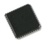
| 供应商器件封装 | 48-LFCSP-VQ(7x7) |
| 分辨率 | 24 bit |
| 包装 | 托盘 |
| 商标 | Analog Devices |
| 安装风格 | SMD/SMT |
| 封装 | Tray |
| 封装/外壳 | 48-VFQFN 裸露焊盘,CSP |
| 封装/箱体 | LFCSP-48 |
| 工作电源电压 | 3.3 V |
| 工厂包装数量 | 260 |
| 接口类型 | Serial (4-Wire, SPI) |
| 最大工作温度 | + 85 C |
| 最小工作温度 | - 40 C |
| 标准包装 | 1 |
| 特性 | 通用 IF 子系统 |
| 电压参考 | Internal |
| 系列 | AD9864 |
| 结构 | Sigma-Delta |
| 视频文件 | http://www.digikey.cn/classic/video.aspx?PlayerID=1364138032001&width=640&height=505&videoID=2245193150001 |
| 转换速率 | 375 kS/s |
| 输入类型 | Single-Ended |
| 通道数量 | 1 Channel |
| 频率 | 10MHz ~ 300MHz |

.jpg)


- 商务部:美国ITC正式对集成电路等产品启动337调查
- 曝三星4nm工艺存在良率问题 高通将骁龙8 Gen1或转产台积电
- 太阳诱电将投资9.5亿元在常州建新厂生产MLCC 预计2023年完工
- 英特尔发布欧洲新工厂建设计划 深化IDM 2.0 战略
- 台积电先进制程称霸业界 有大客户加持明年业绩稳了
- 达到5530亿美元!SIA预计今年全球半导体销售额将创下新高
- 英特尔拟将自动驾驶子公司Mobileye上市 估值或超500亿美元
- 三星加码芯片和SET,合并消费电子和移动部门,撤换高东真等 CEO
- 三星电子宣布重大人事变动 还合并消费电子和移动部门
- 海关总署:前11个月进口集成电路产品价值2.52万亿元 增长14.8%


PDF Datasheet 数据手册内容提取
IF Digitizing Subsystem Data Sheet AD9864 FEATURES GENERAL DESCRIPTION 10 MHz to 300 MHz input frequency The AD98641 is a general-purpose IF subsystem that digitizes a 6.8 kHz to 270 kHz output signal bandwidth low level, 10 MHz to 300 MHz IF input with a signal bandwidth 7.5 dB single sideband noise figure (SSB NF) ranging from 6.8 kHz to 270 kHz. The signal chain of the AD9864 −7.0 dBm input third-order intercept (IIP3) consists of a low noise amplifier (LNA), a mixer, a band-pass Σ-∆ AGC free range up to −34 dBm analog-to-digital converter (ADC), and a decimation filter with 12 dB continuous AGC range programmable decimation factor. An automatic gain control 16 dB front-end attenuator (AGC) circuit gives the AD9864 12 dB of continuous gain Baseband I/Q 16-bit (or 24-bit) serial digital output adjustment. Auxiliary blocks include both clock and local LO and sampling clock synthesizers oscillator (LO) synthesizers. Programmable decimation factor, output format, AGC, and The high dynamic range of the AD9864 and inherent antialiasing synthesizer settings provided by the band-pass Σ-∆ converter allow the device to cope 370 Ω input impedance with blocking signals up to 95 dB stronger than the desired signal. 2.7 V to 3.6 V supply voltage This attribute often reduces the cost of a radio by reducing IF Low current consumption: 17 mA filtering requirements. Also, it enables multimode radios of varying 48-lead LFCSP package channel bandwidths, allowing the IF filter to be specified for the APPLICATIONS largest channel bandwidth. Multimode narrow-band radio products The SPI port programs numerous parameters of the AD9864, Analog/digital UHF/VHF FDMA receivers allowing the device to be optimized for any given application. TETRA, APCO25, GSM/EDGE Programmable parameters include synthesizer divide ratios, AGC Portable and mobile radio products attenuation and attack/decay time, received signal strength level, SATCOM terminals decimation factor, output data format, 16 dB attenuator, and the selected bias currents. The AD9864 is available in a 48-lead LFCSP package and operates from a single 2.7 V to 3.6 V supply. The total power consumption is typically 56 mW and a power-down mode is provided via serial interfacing. FUNCTIONAL BLOCK DIAGRAM MXOPMXON IF2P IF2N GCP GCN DAC AGC AD9864 –16dB IFIN LNA Σ-ΔADC DECFIILMTAETRION FORMATTING/SSI DOUTA DOUTB FS CLKOUT FREF CONTROL LOGIC SLYON CLK SYN REVFOELRTAEGNCEE SPI IOUTL LOP LON IOUTC CLKP CLKN VREFPVCM VREFN PC PD PE SYNCB LLOOO VPC FOILATNEDR LOOP FILTER 04319-0-001 Figure 1. 1 Protected by U.S. Patent No. 5,969,657; other patents pending. Rev. A Document Feedback Information furnished by Analog Devices is believed to be accurate and reliable. However, no responsibility is assumed by Analog Devices for its use, nor for any infringements of patents or other One Technology Way, P.O. Box 9106, Norwood, MA 02062-9106, U.S.A. rights of third parties that may result from its use. Specifications subject to change without notice. No license is granted by implication or otherwise under any patent or patent rights of Analog Devices. Tel: 781.329.4700 ©2003–2016 Analog Devices, Inc. All rights reserved. Trademarks and registered trademarks are the property of their respective owners. Technical Support www.analog.com
AD9864 Data Sheet TABLE OF CONTENTS Features .............................................................................................. 1 SSI Control Registers ................................................................. 21 Applications ....................................................................................... 1 Synchronization Using SYNCB ................................................ 24 General Description ......................................................................... 1 Interfacing to DSPs .................................................................... 24 Functional Block Diagram .............................................................. 1 Power Control ............................................................................. 24 Revision History ............................................................................... 2 LO Synthesizer ............................................................................ 25 Specifications ..................................................................................... 3 Clock Synthesizer ....................................................................... 26 Digital Specifications ................................................................... 5 IF LNA/Mixer ............................................................................. 28 Absolute Maximum Ratings ............................................................ 6 Band-Pass Σ-Δ ADC .................................................................. 29 Thermal Resistance ...................................................................... 6 Decimation Filter ....................................................................... 32 ESD Caution .................................................................................. 6 Variable Gain Amplifier Operation with Automatic Pin Configuration and Functional Descriptions .......................... 7 Gain Control ............................................................................... 33 Typical Performance Characteristics ............................................. 9 Applications Considerations ..................................................... 38 Terminology .................................................................................... 14 External Passive Component Requirements .......................... 40 Serial Peripheral Interface (SPI) ................................................... 15 Applications ................................................................................ 40 Theory of Operation ...................................................................... 17 Layout Example, Evaluation Board, and Software ................. 45 Introduction ................................................................................ 17 SPI Initialization Example ......................................................... 45 Serial Port Interface (SPI) .......................................................... 18 Device SPI Initialization ............................................................ 46 Power-On Reset .......................................................................... 19 Outline Dimensions ....................................................................... 47 Synchronous Serial Interface (SSI) ........................................... 19 Ordering Guide .......................................................................... 47 REVISION HISTORY 2/16—Rev. 0 to Rev. A Changes to Band-Pass Σ-Δ ADC Section and Table 20 ............ 30 Changes to Figure 2 .......................................................................... 7 Changes to Table 21 ....................................................................... 31 Changes to Typical Performance Characteristics Section ........... 9 Changes to Variable Gain Control Section ................................. 34 Changes to Figure 19 ...................................................................... 11 Deleted Table 17 ............................................................................. 34 Changes to Table 6 .......................................................................... 16 Added Figure 64 ............................................................................. 36 Changed General Description Section to Introduction Section ... 17 Changes to Figure 72...................................................................... 40 Changes to Serial Port Interface (SPI) Section ........................... 18 Changes to Layout Example, Evaluation Board, and Added Figure 31; Renumbered Sequentially .............................. 19 Software Section ............................................................................. 45 Added Power-On Reset Section ................................................... 19 Added Figure 77 and SPI Initialization Example Section ......... 45 Deleted Table 9; Renumbered Sequentially ................................ 19 Added Device SPI Initialization Section and Table 24 .............. 46 Added SSI Control Registers Section and Table 8 to Table 13 .... 21 Updated Outline Dimensions ....................................................... 47 Changes to Synchronization Using SYNCB Section and Changes to Ordering Guide .......................................................... 47 Figure 38 .......................................................................................... 24 Changes to Clock Synthesizer Section ......................................... 26 8/03—Revision 0: Initial Version Rev. A | Page 2 of 47
Data Sheet AD9864 SPECIFICATIONS VDDI = VDDF = VDDA = VDDC = VDDL = VDDH = 2.7 V to 3.6 V, VDDQ = VDDP = 2.7 V to 5.5 V, f = 18 MSPS, f = 109.65 MHz, CLK IF f = 107.4 MHz, f = 16.8 MHz, unless otherwise noted. Standard operating mode: VGA at minimum attenuation setting, synthesizers LO REF in normal (not fast acquire) mode, decimation factor = 900, 16-bit digital output, and 10 pF load on SSI output pins. Table 1. Parameter Temperature Test Level Min Typ Max Unit SYSTEM DYNAMIC PERFORMANCE1 SSB Noise Figure at Minimum VGA Attenuation2, 3 Full IV 7.5 9.5 dB SSB Noise Figure at Maximum VGA Attenuation2, 3 Full IV 13 dB Dynamic Range with AGC Enabled2, 3 Full IV 91 95 dB IF Input Clip Point at Maximum VGA Attenuation3 Full IV −20 −19 dBm IF Input Clip Point at Minimum VGA Attenuation3 Full IV −32 −31 dBm Input Third-Order Intercept (IIP3) Full IV −12 −7.0 dBm Gain Variation over Temperature Full IV 0.7 2 dB LNA + MIXER Maximum RF and LO Frequency Range Full IV 300 500 MHz LNA Input Impedance 25°C V 370||1.4 Ω||pF Mixer LO Input Resistance 25°C V 1 kΩ LO SYNTHESIZER LO Input Frequency Full IV 7.75 300 MHz LO Input Amplitude Full IV 0.3 2.0 V p-p FREF Frequency (for Sinusoidal Input Only) Full IV 8 26 MHz FREF Input Amplitude Full IV 0.3 3 V p-p FREF Slew Rate Full IV 7.5 V/µs Minimum Charge Pump Current at 5 V4 Full VI 0.67 mA Maximum Charge Pump Current at 5 V4 Full VI 5.3 mA Charge Pump Output Compliance5 Full VI 0.4 VDDP − 0.4 V Synthesizer Resolution Full IV 6.25 kHz CLOCK SYNTHESIZER CLK Input Frequency Full IV 13 26 MHz CLK Input Amplitude Full IV 0.3 VDDC V p-p Minimum Charge Pump Output Current4 Full VI 0.67 mA Maximum Charge Pump Output Current4 Full VI 5.3 mA Charge Pump Output Compliance5 Full VI 0.4 VDDQ − 0.4 V Synthesizer Resolution Full VI 2.2 kHz Σ-∆ ADC Resolution Full IV 16 24 Bits Clock Frequency (f ) Full IV 13 26 MHz CLK Center Frequency Full V f /8 MHz CLK Pass-Band Gain Variation Full IV 1.0 dB Alias Attenuation Full IV 80 dB GAIN CONTROL Programmable Gain Step Full V 16 dB AGC Gain Range Full V 12 dB GCP Output Resistance Full IV 50 72.5 95 kΩ Rev. A | Page 3 of 47
AD9864 Data Sheet Parameter Temperature Test Level Min Typ Max Unit OVERALL Analog Supply Voltage (VDDA, VDDF, VDDI) Full VI 2.7 3.0 3.6 V Digital Supply Voltage (VDDD, VDDC, VDDL) Full VI 2.7 3.0 3.6 V Interface Supply Voltage (VDDH)6 Full VI 1.8 3.6 V Charge Pump Supply Voltage (VDDP, VDDQ) Full VI 2.7 5.0 5.5 V Total Current Operation Mode7 Full VI 17 mA Standby Full VI 0.01 mA OPERATING TEMPERATURE RANGE −40 +85 °C 1 This includes 0.9 dB loss of matching network. 2 AGC with DVGA enabled. 3 Measured in 10 kHz bandwidth. 4 Programmable in 0.67 mA steps. 5 Voltage span in which LO (or CLK) charge pump output current is maintained within 5% of nominal value of VDDP/2 (or VDDQ/2). 6 VDDH must be less than VDDD + 0.5 V. 7 Clock VCO off and additional 0.7 mA with VGA at maximum attenuation. Rev. A | Page 4 of 47
Data Sheet AD9864 DIGITAL SPECIFICATIONS VDDI = VDDF = VDDA = VDDC = VDDL = VDDH = 2.7 V to 3.6 V, VDDQ = VDDP = 2.7 V to 5.5 V, f = 18 MSPS, f = 109.65 MHz, CLK IF f = 107.4 MHz, f = 16.8 MHz, unless otherwise noted. Standard operating mode: VGA at minimum attenuation setting, synthesizers LO REF in normal (not fast acquire) mode, decimation factor = 900, 16-bit digital output, and 10 pF load on SSI output pins. Table 2. Parameter Temperature Test Level Min Typ Max Unit DECIMATOR Decimation Factor1 Full IV 48 960 Pass-Band Width Full V 50% f CLKOUT Pass-Band Gain Variation Full IV 1.2 dB Alias Attenuation Full IV 88 dBm SPI READ OPERATION (See Figure 30) PC Clock Frequency Full IV 10 MHz PC Clock Period (t ) Full IV 100 ns CLK PC Clock High (t ) Full IV 45 ns HI PC Clock Low (t ) Full IV 45 ns LOW PC to PD Setup Time (t ) Full IV 2 ns DS PC to PD Hold Time (t ) Full IV 2 ns DH PE to PC Setup Time (t) Full IV 5 ns S PC to PE Hold Time (t ) Full IV 5 ns H SPI WRITE OPERATION2 (See Figure 29) PC Clock Frequency Full IV 10 MHz PC Clock Period (t ) Full IV 100 ns CLK PC Clock High (t ) Full IV 45 ns HI PC Clock Low (t ) Full IV 45 ns LOW PC to PD Setup Time (t ) Full IV 2 ns DS PC to PD Hold Time (t ) Full IV 2 ns DH PC to PD (or DOUTB) Data Valid Time (t ) Full IV 3 ns DV PE to PD Output Valid to High-Z (t ) Full IV 8 ns EZ SSI2 (See Figure 33) CLKOUT Frequency Full IV 0.867 26 MHz CLKOUT Period (t ) Full IV 38.4 1153 ns CLK CLKOUT Duty Cycle (t , t ) Full IV 33 50 67 ns HI LOW CLKOUT to FS Valid Time (t ) Full IV −1 +1 ns V CLKOUT to DOUT Data Valid Time (t ) Full IV −1 +1 ns DV CMOS LOGIC INPUTS3 Logic 1 Voltage (V ) Full IV 0.7 × VDDH V IH Logic 0 Voltage (V ) Full IV 0.3 × VDDH V IL Logic 1 Current (I ) Full IV 10 µA IH Logic 0 Current (I ) Full IV 10 µA IL Input Capacitance Full IV 3 pF CMOS LOGIC OUTPUTS2, 3, 4 Logic 1 Voltage (V ) Full IV VDDH − 0.2 V OH Logic 0 Voltage (V ) Full IV 0.2 V OL 1 Programmable in steps of 48 or 60. 2 CMOS output mode with CLOAD = 10 pF and drive strength = 7. 3 Absolute maximum and minimum input/output levels are VDDH + 0.3 V and −0.3 V. 4 IOL = 1 mA; specification is also dependent on drive strength setting. Rev. A | Page 5 of 47
AD9864 Data Sheet ABSOLUTE MAXIMUM RATINGS Table 3. AD9864 Absolute Maximum Ratings Stresses at or above those listed under Absolute Maximum Parameter With Respect To Rating Ratings may cause permanent damage to the product. This is a VDDF, VDDA, VDDC, GNDF, GNDA, GNDC, −0.3 to +4.0 stress rating only; functional operation of the product at these VDDD, VDDH, VDDL, GNDD, GNDH, GNDL, or any other conditions above those indicated in the operational VDDI GNDI, GNDS section of this specification is not implied. Operation beyond VDDF, VDDA, VDDC, VDDR, VDDA, VDDC, −4.0 V to +4.0 V the maximum operating conditions for extended periods may VDDD, VDDH, VDDL, VDDD, VDDH, VDDL, VDDI VDDI affect product reliability. VDDP, VDDQ GNDP, GNDQ −0.3 V to +6.0 V THERMAL RESISTANCE GNDF, GNDA, GNDC, GNDF, GNDA, GNDC, −0.3 V to +0.3 V GNDD, GNDH, GNDL, GNDD, GNDH, GNDL, θJA is specified for the worst-case conditions, that is, θJA is GNDI, GNDQ, GNDP, GNDI, GNDQ, GNDP, specified for device soldered in circuit board for surface-mount GNDS GNDS packages. MXOP, MXON, LOP, LON, GNDH −0.3 V to IFIN, CXIF, CXVL, CXVM VDDI + 0.3 V Table 4. Thermal Resistance PC, PD, PE, CLKOUT, GNDH −0.3 V to Package Type θ Unit DOUTA, DOUTB, FS, VDDH + 0.3 V JA SYNCB 48-Lead LFCSP 29.5 °C/W IF2N, IF2P, GCP, GCN GNDF −0.3 V to VDDF + 0.3 V ESD CAUTION VFEFP, VREGN, RREF GNDA −0.3 V to VDDA + 0.3 V IOUTC GNDQ −0.3 V to VDDQ + 0.3 V IOUTL GNDP −0.3 V to VDDP + 0.3 V CLKP, CLKN GNDC −0.3 V to VDDC + 0.3 V FREF GNDL −0.3 V to VDDL + 0.3 V Maximum Junction 150°C Temperature Storage Temperature −65°C to +150°C Maximum Lead 300°C Temperature Rev. A | Page 6 of 47
Data Sheet AD9864 PIN CONFIGURATION AND FUNCTIONAL DESCRIPTIONS VDDI IFIN CXIF GNDI CXVL LOP LON CXVM VDDL VDDP IOUTL GNDP 48 47 46 45 44 43 42 41 40 39 38 37 MXOP 1 36 GNDL PIN 1 MXON 2 IDENTIFIER 35 FREF GNDF 3 34 GNDS IF2N 4 33 SYNCB IF2P 5 32 GNDH AD9864 VDDF 6 31 FS TOP VIEW GCP 7 (Not to Scale) 30 DOUTB GCN 8 29 DOUTA VDDA 9 28 CLKOUT GNDA 10 27 VDDH VREFP 11 26 VDDD VREFN 12 25 PE 13 14 15 16 17 18 19 20 21 22 23 24 F Q C Q C C P N S D C D E D T D D D K K D D P P R D U N D N L L N N R V O G V G C C G G I N1 . O EATX EPPSCOBS GEDR OPUANDD. T PHAED B ISA COKPSTIIDOEN PAALD.DLE CONTACT IS NOT CONNECTED TO GROUND. 04319-0-002 Figure 2. 48-Lead LFCSP Pin Configuration Table 5. 48-Lead Lead Frame Chip Scale Package (LFCSP) Pin Function Descriptions Pin No. Mnemonic Description 1 MXOP Mixer Output, Positive. 2 MXON Mixer Output, Negative. 3 GNDF Ground for Front End of ADC. 4 IF2N Second IF Input (to ADC), Negative. 5 IF2P Second IF Input (to ADC), Positive. 6 VDDF Positive Supply for Front End of ADC. 7 GCP Filter Capacitor for ADC Full-Scale Control. 8 GCN Full-Scale Control Ground. 9 VDDA Positive Supply for ADC Back End. 10 GNDA Ground for ADC Back End. 11 VREFP Voltage Reference, Positive. 12 VREFN Voltage Reference, Negative. 13 RREF Reference Resistor: Requires 100 kΩ to GNDA. 14 VDDQ Positive Supply for Clock Synthesizer. 15 IOUTC Clock Synth Charge Pump Out Current. 16 GNDQ Ground for Clock Synthesizer Charge Pump. 17 VDDC Positive Supply for Clock Synthesizer. 18 GNDC Ground for Clock Synthesizer. 19 CLKP Sampling Clock Input/Clock VCO Tank, Positive. 20 CLKN Sampling Clock Input/Clock VCO Tank, Negative. 21 GNDS Substrate Ground. 22 GNDD Ground for Digital Functions. 23 PC Clock Input for SPI Port. 24 PD Data I/O for SPI Port. 25 PE Enable Input for SPI Port. 26 VDDD Positive Supply for Internal Digital. 27 VDDH Positive Supply for Digital Interface. 28 CLKOUT Clock Output for SSI Port. 29 DOUTA Data Output for SSI Port. 30 DOUTB Data Output for SSI Port (Inverted) or SPI Port. 31 FS Frame Sync for SSI Port. Rev. A | Page 7 of 47
AD9864 Data Sheet Pin No. Mnemonic Description 32 GNDH Ground for Digital Interface. 33 SYNCB Resets SSI and Decimator Counters; Active Low. Connect to VDDH if unused. 34 GNDS Substrate Ground. 35 FREF Reference Frequency Input for Both Synthesizers. 36 GNDL Ground for LO Synthesizer. 37 GNDP Ground for LO Synthesizer Charge Pump. 38 IOUTL LO Synthesizer Charge Pump Out Current. 39 VDDP Positive Supply for LO Synthesizer Charge Pump. 40 VDDL Positive Supply for LO Synthesizer. 41 CXVM External Filter Capacitor; DC Output of LNA. 42 LON LO Input to Mixer and LO Synthesizer, Negative. 43 LOP LO Input to Mixer and LO Synthesizer, Positive. 44 CXVL External Bypass Capacitor for LNA Power Supply. 45 GNDI Ground for Mixer and LNA. 46 CXIF External Capacitor for Mixer V-I Converter Bias. 47 IFIN First IF Input (to LNA). 48 VDDI Positive Supply for LNA and Mixer. EPAD Exposed Pad. The backside paddle contact is not connected to ground. A PCB ground pad is optional. Rev. A | Page 8 of 47
Data Sheet AD9864 TYPICAL PERFORMANCE CHARACTERISTICS VDDI = VDDF = VDDA = VDDC = VDDL = VDDH = VDDx , VDDQ = VDDP = 2.7 V to 5.5 V, f = 18 MSPS, f = 109.65 MHz, CLK IF f = 107.4 MHz, f = 16.8 MHz, T =25 Co, LO and CLK synthesizer disabled, 16-bit data with AGC and DVGA enabled, unless LO REF A otherwise noted. 9.5 0 9.0 –2 +85°C 8.5 –4 NF (dB) 78..50 +25°C IIP3 (dBm) –6 ++8255°C°C –8 7.0 –40°C –40°C –10 6.5 6.02.7 3.0 VDDx (V) 3.3 3.6 04319-0-003 –122.7 3.0 VDDx (V) 3.3 3.6 04319-0-006 Figure 3. SSB Noise Figure vs. Supply Figure 6. IIP3 vs. Supply 98 –17.5 97 –18.0 +25°C m) 96 B –18.5 B) –40°C NT (d +85°C R (d 95 POI –19.0 +25°C D P LI C 94 T –19.5 +85°C PU –40°C N I 93 –20.0 922.7 3.0 VDDx (V) 3.3 3.6 04319-0-004 –20.52.7 3.0 VDDx (V) 3.3 3.6 04319-0-007 Figure 4. Dynamic Range (DR) vs. Supply Figure 7. Maximum VGA Attenuation Clip Point vs. Supply –29.5 0.1 0 –30.0 –0.1 m) B B) d d –0.2 NT ( –30.5 ON ( OI TI –0.3 P A P RI T CLI –31.0 +85°C N VA –0.4 U AI –0.5 INP +25°C G –0.6 –31.5 –0.7 –40°C –32.02.7 3.0 VDDx (V) 3.3 3.6 04319-0-005 –0.8–20 –17 L–O14 DRIVE (dB–m11) –8 –5 04319-0-008 Figure 5. Minimum VGA Attenuation Clip Point vs. Supply Figure 8. Normalized Gain Variation vs. LO Drive (VDDx = 3.0 V) Rev. A | Page 9 of 47
AD9864 Data Sheet VDDI = VDDF = VDDA = VDDC = VDDL = VDDH = 3.0 V , VDDQ = VDDP = 2.7 V to 5.5 V, f = 18 MSPS, f = 109.65 MHz, f = CLK IF LO 107.4 MHz, f = 16.8 MHz, T =25 Co, LO and CLK synthesizer disabled, unless otherwise noted. REF A 9.0 0 –12 8.8 –10 –15 8.6 c) –20 dB –18 E (dBc) 88..42 –30 6 dBm ( –21 OISE FIGUR 78..80 INMFD ––4500 TH IFIN =–3 dBm ––2247 N 7.6 WI –60 D –30 7.4 IM –70 –33 7.2 7.0–20 –15 –L1O0 DRIVE (dB–m5) 0 5–80 04319-0-009 –36–36 –33 –30 –27 –24IF–I2N1 (d–B1m8)–15 –12 –9 –6 –3 –0 04319-0-012 Figure 9. Noise Figure and IMD vs. LO Drive (VDDx = 3.0 V) Figure 12. Gain Compression vs. IFIN with 16 dB LNA Attenuator Enabled 0 –55 –15 ADC DOES NOT GO INTO HARD COMPRESSION –61 –18 –2 PIN 3.6V –67 –21 3.3V 2.7V –4 –73 –24 S –6 Bm) –79 3.0V –27 FS) dBF –8 3.0V MD (d –85 3.3V –30 N (dB 2.7V I –91 –33 PI –10 –97 –36 3.6V –103 –39 –12 –109 –42 –14–30 –28 –26 –24IFIN– (2d2Bm)–20 –18 –16 –14 04319-0-010 –115–51 –48 –45 –I4F2IN (dB–m3)9 –36 –33 –30–45 043190013 Figure 10. Gain Compression vs. IFIN Figure 13. IMD vs. IFIN 10.0 10.0 9.5 9.5 16-BIT 16-BIT 16-BIT E (dB) 9.0 I/Q DATA DI/VQG DAA ETNAA WBLITEHD E (dB) 9.0 DATA R R 16-BIT DATA GU GU WITH DVGA ENABLED FI FI SE 8.5 SE 8.5 OI OI N N 8.0 8.0 24-BIT 24-BIT I/Q DATA DATA 7.510 CHANNEL BA1N0D0WIDTH (kHz) 1000 04319-0-011 7.510 CHANNEL B1A0N0DWIDTH (kHz) 1000 04319-0-014 Figure 11. Noise Figure vs. Bandwidth Figure 14. Noise Figure vs. Bandwidth (Minimum Attenuation, fCLK = 13 MSPS) (Minimum Attenuation, fCLK = 18 MSPS) Rev. A | Page 10 of 47
Data Sheet AD9864 VDDI = VDDF = VDDA = VDDC = VDDL = VDDH = 3.0 V , VDDQ = VDDP = 2.7 V to 5.5 V, f = 18 MSPS, f = 109.65 MHz, f = CLK IF LO 107.4 MHz, f = 16.8 MHz, T =25 Co, LO and CLK Synthesizer Disabled, unless otherwise noted. REF A 10.0 11.5 16-BIT DATA WITH DVGA ENABLED 11.0 9.5 10.5 BW = 27.08kHz URE (dB) 9.0 1D6A-BTIAT 2D4A-BTIAT URE (dB) 109..05 B(WK == 01,2 M.0 4=k 8H)z(K = 0, M = 3) G G E FI E FI 9.0 NOIS 8.5 NOIS 8.5 (BKW = =0 ,6 M.7 8=k 1H5z) 8.0 8.0 7.5 7.510 CHANNEL BA1N0D0WIDTH (kHz) 100004319-0-015 7.00 3 VGA ATTEN6UATION (dB) 9 12 04319-0-018 Figure 15. Noise Figure vs. Bandwidth Figure 18. Noise Figure vs. VGA Attenuation (fCLK = 13 MSPS) (Minimum Attenuation, fCLK = 26 MSPS) 14 14 13 13 BW = 75kHz BW = 135.42kHz (K = 0, M = 1) (K = 1, M = 1) BW = 90.28kHz 12 12 B) BW = 50kHz B) (K = 1, M = 2) d d E ( (K = 0, M = 2) E ( R 11 R 11 GU BW = 15kHz GU FI (K = 0, M = 9) FI E 10 E 10 OIS OIS BW = 27.08kHz N N (K = 1, M = 9) 9 9 8 8 70 3 VGA ATTEN6UATION (dB) 9 12 04319-0-016 70 3 VGAATTENU6ATION (dB) 9 12 04319-0-019 Figure 16. Noise Figure vs. VGA Attenuation (fCLK = 18 MSPS) Figure 19. Noise Figure vs. VGA Attenuation (fCLK = 26 MSPS) –30 –5 –30 –5 –40 –10 –40 –10 –50 –50 PIN –15 PIN –15 –60 –60 dBFS) –70 IMD –20 FS) BFS) –70 IMD –20 FS) IMD ( ––8900 ––3205 PIN (dB IMD (d ––8900 ––3205 PIN (dB –100 –100 –35 –35 –110 –110 –40 –40 –120 –120 –130–45 –42 –39 –36IFIN (–d3B3) –30 –27 –24 –45 04319-0-017 –13–045 –42 –39 –I3F6IN (dBm–)33 –30 –27 –24 –45 04319-0-020 Figure 17. IMD vs. IFIN (fCLK = 13 MSPS) Figure 20. IMD vs. IFIN (fCLK = 18 MSPS) Rev. A | Page 11 of 47
AD9864 Data Sheet VDDI = VDDF = VDDA = VDDC = VDDL = VDDH = 3.0 V , VDDQ = VDDP = 2.7 V to 5.5 V, f = 18 MSPS, f = 109.65 MHz, f = CLK IF LO 107.4 MHz, f = 16.8 MHz, T =25 Co, LO and CLK synthesizer disabled, 16-bit data with AGC and DVGA enabled, unless otherwise noted. REF A –30 –5 13 –40 –10 12 –50 16-BIT WITH DVGA PIN –15 –60 B) 11 d IMD (dBFS) –––789000 IMD –––322005 PIN (dBFS) OISE FIGURE ( 109 24-BIT –100 N 8 –35 –110 –40 7 –120 –130–45 –42 –39 –IF3I6N (dB–m3)3 –30 –27 –24 –45 04319-0-021 60 50 100 150FR2E00QUE2N5C0Y (3M0H0z) 350 400 450 500 04319-0-024 Figure 21. IMD vs. IFIN (fCLK = 26 MSPS) Figure 24. Noise Figure vs. Frequency (Minimum Attenuation, fCLK = 18 MSPS, BW = 10 kHz) 13 0 16-BIT WITH DVGA 12 –2 B) 11 d RE ( 10 m) –4 U B G d OISE FI 9 24-BIT IIP3 ( –6 N 8 –8 7 60 50 100 150 FR2E00QUE2N5C0Y (3M0H0z) 350 400 450 500 04319-0-022 –100 50 100 150FR2E00QUE2N5C0Y (3M0H0z) 350 400 450 500 04319-0-025 Figure 22. Noise Figure vs. Frequency Figure 25. Input IIP3 vs. Frequency (fCLK = 18 MSPS) (Minimum Attenuation, fCLK = 26 MSPS, BW = 10 kHz) 0 20.0 128 18.5 112 –2 AGC 17.0 96 E Bc) ALU m) –4 E (d 15.5 80 N V IIP3 (dB –6 NOISE FIGUR 1142..05 NOISE FIGURE 4684 MEAN AGC ATT 11.0 32 –8 9.5 16 –100 50 100 150 FR2E00QUE2N50CY (3M0H0z)350 400 450 500 04319-0-023 8.–055 –50 –45 –4IN0TER–3F5ERE–R3 0LEV–E2L5 (dB–m20) –15 –10 –50 04319-0-026 Figure 23. Input IIP3 vs. Frequency (fCLK = 26 MSPS) Figure 26. Noise Figure vs. Interferer Level (16-Bit Data, BW = 12.5 kHz, AGCR = 1, fINTERFERER = fIF + 110 kHz) Rev. A | Page 12 of 47
Data Sheet AD9864 VDDI = VDDF = VDDA = VDDC = VDDL = VDDH = 3.0 V , VDDQ = VDDP = 2.7 V to 5.5 V, f = 18 MSPS, f = 109.65 MHz, f = CLK IF LO 107.4 MHz, f = 16.8 MHz, T =25 Co, LO and CLK Synthesizer Disabled, AGC enabled, unless otherwise noted. REF A 16 256 16 128 15 224 15 AGC ATTN AGC ATTN 14 192 E 14 96 E Bc) ALU Bc) ALU E FIGURE (d1132 NOISE FIGURE 116208 AGC ATTN V E FIGURE (d1132 64 AGC ATTN V OIS11 96 AN OIS11 AN N E N NOISE FIGURE E M M 10 64 10 32 9 32 9 8–50 –45 –40INTE–R3F5ERE–R3 L0EVEL– 2(d5Bm)–20 –15 –100 04319-0-027 8–65 –55 IN–T4E5RFERER–3 L5EVEL (d–B25m) –15 –50 04319-0-028 Figure 27. Noise Figure vs. Interferer Level (16-Bit Data with DVGA, Figure 28. Noise Figure vs. Interferer Level (24-Bit Data, BW = 12.5 kHz, AGCR = 1, fINTERFERER = fIF + 110 kHz) BW = 12.5 kHz, AGCR = 1, fINTERFERER = fIF + 110 kHz) Rev. A | Page 13 of 47
AD9864 Data Sheet TERMINOLOGY Single Sideband Noise Figure (SSB NF) Dynamic Range (DR) Noise figure (NF) is defined as the degradation in SNR Dynamic range is the measure of a small target input signal performance (in dB) of an IF input signal after it passes through (P ) in the presence of a large unwanted interferer signal TARGET a component or system. It can be expressed with the equation (P ). Typically, the large signal causes some unwanted INTER characteristic of the component or system to degrade, thus Noise Figure = 10 × log(SNR /SNR ) IN OUT making it unable to detect the smaller target signal correctly. The term SSB is applicable for heterodyne systems containing a For the AD9864, it is often a degradation in noise figure at mixer. It indicates that the desired signal spectrum resides on only increased VGA attenuation settings that limits its dynamic one side of the LO frequency (that is, single sideband); therefore, range. a noiseless mixer has a noise figure of 3 dB. The test method for the AD9864 is as follows. The small target The SSB noise figure of the AD9864 is determined by the equation signal (an unmodulated carrier) is input at the center of the IF SSB NF = PIN − [10 × log(BW)] − (−174 dBm/Hz) − SNR frequency, and its power level (PTARGET) is adjusted to achieve an SNR of 6 dB. The power of the signal is then increased by where: TARGET 3 dB prior to injecting the interferer signal. The offset frequency P is the input power of an unmodulated carrier. IN of the interferer signal is selected so that aliases produced by BW is the noise measurement bandwidth. the response of the decimation filter, as well as phase noise from −174 dBm/Hz is the thermal noise floor at 293 K. the LO (due to reciprocal mixing), do not fall back within the SNR is the measured signal-to-noise ratio in dB of the AD9864. measurement bandwidth. For this reason, an offset of 110 kHz Note that P is set to −85 dBm to minimize any degradation in IN was selected. The interferer signal (also an unmodulated carrier) measured SNR due to phase noise from the RF and LO signal is then injected into the input and its power level is increased to generators. The IF frequency, CLK frequency, and decimation the point (P ) where the target signal SNR is reduced to 6 dB. INTER factors are selected to minimize any spurious components The dynamic range is determined with the equation falling within the measurement bandwidth. Note also that a DR = P − P + SNR bandwidth of 10 kHz is used for the data sheet specification. All INTER TARGET TARGET references to noise figures within this data sheet imply single Note that the AGC of the AD9864 is enabled for this test. sideband noise figure. IF Input Clip Point Input Third-Order Intercept (IIP3) The IF input clip point is defined as the input power that results IIP3 is a figure of merit used to determine the susceptibility of a in a digital output level 2 dB below full scale. Unlike other linear component or system to intermodulation distortion (IMD) from components that typically exhibit a soft compression its third-order nonlinearities. Two unmodulated carriers at a (characterized by its 1 dB compression point), an ADC exhibits specified frequency relationship (f1 and f2) are injected into a a hard compression when its input signal exceeds its rated nonlinear system exhibiting third-order nonlinearities producing maximum input signal range. For the AD9864, which contains IMD components at 2f1 − f2 and 2f2 − f1. IIP3 graphically a Σ-∆ ADC, hard compression must be avoided because it represents the extrapolated intersection of the carrier’s input causes severe SNR degradation. power with the third-order IMD component when plotted in dB. The difference in power (D in dBc) between the two carriers, and the resulting third-order IMD components can be determined from the equation D = 2 × (IIP3 − P ) IN Rev. A | Page 14 of 47
Data Sheet AD9864 SERIAL PERIPHERAL INTERFACE (SPI) The SPI is a bidirectional serial port. It is used to load the configuration information into the registers listed in Table 6, as well as to read back their contents. Table 6 provides a list of the registers that can be programmed through the SPI port. Addresses and default values are given in hexadecimal form. Table 6. SPI Address Map Address Default (Hex) Bit(s) Width Value Name Description Power Control Registers 0x00 [7:0] 8 0xFF STBY Standby control bits (REF, LO, CKO, CK, GC, LNAMX, unused, and ADC). Default is power-up condition of standby. 0x01 [3:2] 2 0x00 CKOB CK oscillator bias (0 = 0.25 mA, 1 = 0.35 mA, 2 = 0.40 mA, 3 = 0.65 mA). [1:0] 2 0x00 ADCB Do not use. 0x02 [7:0] 8 0x00 TEST Factory test mode. Do not use. AGC 0x03 7 1 0 ATTEN Apply 16 dB attenuation in the front end. [6:0] 7 0x00 AGCG [14:8] AGC attenuation setting (7 MSBs of a 15-bit unsigned word). 0x04 [7:0] 8 0x00 AGCG [7:0] AGC attenuation setting (8 LSBs of a 15-bit unsigned word). 0x05 [7:4] 4 0x00 AGCA AGC attack bandwidth setting. Default yields 50 Hz loop bandwidth. [3:0] 4 0x00 AGCD AGC decay time setting. Default is decay time = attack time. 0x06 7 1 0 AGCV Enable digital VGA to increase AGC range by 12 dB. [6:4] 3 0x00 AGCO AGC overload update setting. Default is slowest update. 3 1 0 AGCF Fast AGC (minimizes resistance seen between GCP and GCN). [2:0] 3 0x00 AGCR AGC enable/reference level (disabled, 3 dB, 6 dB, 9 dB, 12 dB, 15 dB below clip). Decimation Factor 0x07 [7:5] 3 Unused 4 1 0 K Decimation factor = 60 × (M + 1), if K = 0; 48 × (M + 1), if K = 1. [3:0] 4 0x04 M Default is decimate-by-300. LO Synthesizer 0x08 [5:0] 6 0x00 LOR [13:8] Reference frequency divider (6 MSBs of a 14-bit word). 0x09 [7:0] 8 0x38 LOR [7:0] Reference frequency divisor (8 LSBs of a 14-bit word). Default (56) yields 300 kHz from f = 16.8 MHz. REF 0x0A [7:5] 3 0x05 LOA A counter (prescaler control counter). [4:0] 5 0x00 LOB [12:8] B counter MSB (5 MSB of a 13-bit word). Default LOA and LOB values yield 300 kHz from 73.35 MHz to 2.25 MHz. 0x0B [7:0] 8 0x1D LOB [7:0] B counter LSB (8 LSB of a 13-bit word). 0x0C 6 1 0 LOF Enable fast acquire. 5 1 0 LOINV Invert charge pump (0 = source current to increase VCO frequency). [4:2] 3 0x00 LOI Charge pump current in normal operation. I = (LOI +1) × 0.625 mA. PUMP [1:0] 2 0x03 LOTM Manual control of LO charge pump (0 = off, 1 = up, 2 = down, and 3 = normal). 0x0D [5:0] 6 0x00 LOFA [13:8] LO fast acquire time unit (6 MSBs of a 14-bit word). 0x0E [7:0] 8 0x04 LOFA [7:0] LO fast acquire time unit (8 LSBs of a 14-bit word). Clock Synthesizer 0x10 [5:0] 6 0x00 CKR [13:8] Reference frequency divisor (6 MSBs of a 14-bit word). 0x11 [7:0] 8 0x38 CKR [7:0] Reference frequency divisor (8 LSBs of a 14-bit word). Default yields 300 kHz from f = 16.8 MHz; minimum = 3, maximum = 16383. REF 0x12 [4:0] 5 0x00 CKN [12:8] Synthesized frequency divisor (5 MSBs of a 13-bit word). 0x13 [7:0] 8 0x3C CKN [7:0] Synthesized frequency divisor (8 LSBs of a 13-bit word). Default yields 300 kHz from 18 MHz; minimum = 3, maximum = 8191. Rev. A | Page 15 of 47
AD9864 Data Sheet Address Default (Hex) Bit(s) Width Value Name Description 0x14 6 1 0 CKF Enable fast acquire. 5 1 0 CKINV Invert charge pump (0 = source current to increase VCO frequency). [4:2] 3 0x00 CKI Charge pump current in normal operation. I = (CKI + 1) × 0.625 mA. PUMP [1:0] 2 0x03 CKTM Manual control of CLK charge pump (0 = off, 1 = up, 2 = down, and 3 = normal). 0x15 [5:0] 6 0x00 CKFA [13:8] CK fast acquire time unit (6 LSBs of a 14-bit word). 0x16 [7:0] 8 0x04 CKFA [7:0] CK fast acquire time unit (8 LSBs of a 14-bit word). SSI Control 0x18 [7:0] 8 0x12 SSICRA SSI Control Register A. See the SSI Control Registers section. Default is FS and CLKOUT three-stated. 0x19 [7:0] 8 0x07 SSICRB SSI Control Register B. See the SSI Control Registers section (16-bit data, maximum drive strength). 0x1A [3:0] 4 0x01 SSIORD Output rate divisor. f = f /SSIORD. CLKOUT CLK ADC Tuning 0x1C 1 1 0 TUNE_LC Perform tuning on LC portion of the ADC (cleared when done). 0 1 0 TUNE_RC Perform tuning on RC portion of the ADC (cleared when done). 0x1D [3:0] 3 0x00 CAPL1 [2:0] Coarse capacitance setting of LC tank (LSB is 25 pF, differential). 0x1E [5:0] 6 0x00 CAPL0 [5:0] Fine capacitance setting of LC tank (LSB is 0.4 pF, differential). 0x1F [7:0] 8 0x00 CAPR Capacitance setting for RC resonator (64 LSB of fixed capacitance). Test Registers and SPI Port Read Enable 0x37 [7:0] 8 0x00 TEST Factory test mode. Do not use. 0x38 [7:1] 7 0x00 TEST Factory test mode. Do not use. 0 1 0 DACCR Manual feedback DAC control 0x39 [7:0] 8 0x00 DACDATA Feedback DAC data setting in manual mode. 0x3A [7:4] 4 0x00 TEST Factory test mode. Do not use. 3 1 0 SPIREN Enable read from SPI port. [2:0] 3 0x00 TEST Factory test mode. Do not use. 0x3B [7:4] 4 0x00 TEST Factory test mode. Do not use. 3 1 0 TRI Three-state DOUTB. [2:0] 3 0x00 TEST Factory test mode. Do not use. 0x3C to [7:0] 8 0x00 TEST Factory test mode. Do not use. 0x3D 0x3E 7 1 0 TEST Factory test mode. Do not use. 6 1 0 OVL ADC overload detector. [5:3] 3 0 TEST Factory test mode. Do not use. 2 2 0 RC_Q RC Q enhancement. 1 1 0 RC_BYP Bypass RC resonator. 0 1 0 SC_BYP Bypass SC resonators. 0x3F [7:0] 8 Subject ID Revision ID (read-only). A write of 0x99 to this register is equivalent to a to change power-on reset. Rev. A | Page 16 of 47
Data Sheet AD9864 THEORY OF OPERATION INTRODUCTION The cascaded decimation factor is programmable from 48 to 960. The decimation filter data is output via the synchronous serial The AD9864 is a general-purpose, narrow-band IF subsystem interface (SSI) of the chip. that digitizes a low level, 10 MHz to 300 MHz IF input with a signal bandwidth ranging from 6.8 kHz to 270 kHz. The signal Additional functionality built into the AD9864 includes LO and chain of the AD9864 consists of an LNA, a mixer, a band-pass clock synthesizers, programmable AGC, and a flexible synchronous Σ-∆ ADC, and a decimation filter with programmable serial interface for output data. decimation factor. The LO synthesizer is a programmable phase-locked loop (PLL) The input LNA is a fixed gain block with an input impedance of consisting of a low noise phase frequency detector (PFD), a approximately 370 Ω||1.4 pF. The LNA input is single-ended variable output current charge pump (CP), a 14-bit reference and self biasing, allowing the input IF to be ac-coupled. The divider, A and B counters, and a dual modulus prescaler. The LNA can be disabled through the serial interface, providing a user only needs to add an appropriate loop filter and VCO for fixed 16 dB attenuation to the input signal. complete operation. The LNA drives the input port of a Gilbert-type active mixer. The clock synthesizer is equivalent to the LO synthesizer with The mixer LO port is driven by the on-chip LO buffer, which can the following differences: be driven externally, single-ended, or differential. The LO buffer • It does not include the prescaler or A counter. inputs are self biasing and allow the LO input to be ac-coupled. • It includes a negative resistance core used for VCO The open-collector outputs of the mixer drive an external generation. resonant tank consisting of a differential LC network tuned to the IF of the band-pass Σ-∆ ADC. The AD9864 contains both a variable gain amplifier (VGA) and a digital VGA (DVGA). Both of these can operate manually or The external differential LC tank forms the resonator for the automatically. In manual mode, the gain for each is programmed first stage of the band-pass Σ-∆ ADC. The tank LC values must through the SPI. In automatic gain control mode, the gains are be selected for a center frequency of f /8, where f is the CLK CLK adjusted automatically to ensure that the ADC does not clip and sample rate of the ADC. The f /8 frequency is the IF digitized CLK that the rms output level of the ADC is equal to a programmable by the band-pass Σ-∆ ADC. On-chip calibration allows reference level. standard tolerance inductor and capacitor values. The calibration is typically performed once at power-up. The VGA has 12 dB of attenuation range and is implemented by adjusting the ADC full-scale reference level. The DVGA gain is The ADC contains a sixth-order, multibit band-pass Σ-∆ implemented by scaling the output of the decimation filter. The modulator that achieves very high instantaneous dynamic range DVGA is most useful in extending the dynamic range in narrow- over a narrow frequency band centered at f /8. The modulator CLK band applications requiring 16-bit I and Q data format. output is quadrature mixed to baseband and filtered by three cascaded linear phase FIR filters to remove out-of-band noise. The SSI provides a programmable frame structure, allowing 24-bit or 16-bit I and Q data and flexibility by including attenuation and The first FIR filter is a fixed, decimate by 12, using a fourth- RSSI data if required. order comb filter. The second FIR filter also uses a fourth-order comb filter with programmable decimation from 1 to 16. The third FIR stage is programmable for decimation of either 4 or 5. Rev. A | Page 17 of 47
AD9864 Data Sheet SERIAL PORT INTERFACE (SPI) register are shifted into the data pin (PD) on the rising edges of the next eight clock cycles. PE stays low during the operation The serial port of the AD9864 has 3-wire or 4-wire SPI capability, and goes high at the end of the transfer. If PE rises before the allowing read/write access to all registers that configure the internal eight clock cycles have passed, the operation is aborted. If PE parameters of the device. The default 3-wire serial communication stays low for an additional eight clock cycles, the destination port consists of a clock (PC), peripheral enable (PE), and address is incremented and another eight bits of data are shifted bidirectional data (PD) signal. The inputs to PC, PE, and PD in. Again, if PE rises early, the current byte is ignored. By using contain a Schmitt trigger with a nominal hysteresis of 0.4 V this implicit addressing mode, the chip can be configured with centered about the digital interface supply, that is, VDDH/2. a single write operation. Registers identified as being subject to A 4-wire SPI interface can be enabled by setting the MSB of the frequent updates, namely those associated with power control SSICRB register (Register 0x19, Bit 7) and setting Register 0x3A and AGC operation, have been assigned adjacent addresses to to 0x00, resulting in the output data appearing on only the minimize the time required to update them. Note that multibyte DOUTB pin with the PD pin functioning as an input pin only. registers are big endian (the most significant byte has the lower Note that because the default power-up state sets DOUTB low, address) and are updated when a write to the least significant bus contention is possible for systems sharing the SPI output byte occurs. line. To avoid any bus contention, the DOUTB pin can be three- Figure 30 and Figure 31 illustrates the timing for 3-wire and stated by setting the fourth control bit in the three-state bit 4-wire SPI read operations. Although the AD9864 does not (Register 0x3B, Bit 3). This bit can then be toggled to gain require read access for proper operation, it is often useful in the access to the shared SPI output line. product development phase or for system authentication. Note An 8-bit instruction header must accompany each read and that the readback enable bit (Register 0x3A, Bit 3) must be set write SPI operation. Only the write operation supports an auto- for a read operation with a 3-wire SPI interface. For 4-wire SPI increment mode, which allows the entire chip to be configured operation, this bit remains low (Register 0x3A = 0x00) but in a single write operation. The instruction header is shown in DOUTB is enabled via the SSICRB register (Register 0x19, Bit 7). Table 7. It includes a read/not-write indicator bit, six address Note that for the 4-wire SPI interface, the eight data bits appear bits, and a Don’t Care bit. The data bits immediately follow the on the DOUTB pin with the same timing relationship as those instruction header for both read and write operations. Note that appearing at PD for 3-wire SPI interface case. the address and data are always given MSB first. After the peripheral enable (PE) signal goes low, data (PD) Table 7. Instruction Header Information pertaining to the instruction header is read on the rising edges MSB LSB of the clock (PC). A read operation occurs if the read/not-write I7 I6 I5 I4 I3 I2 I1 I0 indicator is set high. After the address bits of the instruction R/W A5 A4 A3 A2 A1 A0 X1 header are read, the eight data bits pertaining to the specified register are shifted out of the data pin (PD) on the falling edges 1 X = don’t care. of the next eight clock cycles. After the last data bit is shifted Figure 29 illustrates the timing requirements for a write out, the user must return PE high, causing PD to become three- operation to the SPI port. After the peripheral enable (PE) stated (for 3-wire case) and return to its normal status as an signal goes low, data (PD) pertaining to the instruction header input pin. Since the auto-increment mode is not supported for is read on the rising edges of the clock (PC). To initiate a write read operations, an instruction header is required for each operation, the read/not-write bit is set low. After the instruction register read operation and PE must return high before header is read, the eight data bits pertaining to the specified initiating the next read operation. tCLK tS tH PE tHI tLOW PC tDS PD R/WtDH A5 A4 A0 DCOARNE'T D7 D6 D1 D0 04319-0-029 Figure 29. SPI Write Operation Timing Rev. A | Page 18 of 47
Data Sheet AD9864 tCLK tS PE tHI tLOW PC tDS tDV tEZ PD R/WtDH A5 A1 A0 DCOANR'ET D7 D6 D1 D0 04319-0-130 Figure 30. 3-Wire SPI Read Operation Timing tCLK tS PE tHI tLOW PC tDS tDV tDH DON'T PD R/W A5 A1 A0 CARE DOUTB DCOANR'ETT DCOANR'ET DCOANR'ET DCOANR'ET DCOANR'ET D7 D6 D1 D0 DCOANR'ET 04319-0-030 Figure 31. 4-Wire SPI Read Operation Timing POWER-ON RESET byte contains both a count of modulator reset events and an estimate of the received signal amplitude (relative to full scale of The SPI registers are automatically set to their default settings the AD9864 ADC). Figure 32 illustrates the structure of the SSI upon power-up when the VDDD supply crosses a threshold. This data frames in a number of SSI modes. ensures that the AD9864 is in a known state and placed in standby for minimal power consumption. In the unlikely event that the The two optional bytes are output if the EAGC bit of SSICRA is SPI registers were not reset to their default settings, an equivalent set. The first byte contains the 8-bit attenuation setting (0 = no software reset by writing 0x99 to Register 0x3F can be used as the attenuation, 255 = 24 dB of attenuation), whereas the second byte first SPI write command to provide additional assurance. contains a 2-bit reset field and 6-bit received signal strength field. The reset field contains the number of modulator reset SYNCHRONOUS SERIAL INTERFACE (SSI) events since the last report, saturating at 3. The received signal The AD9864 provides a high degree of programmability of its strength (RSSI) field is a linear estimate of the signal strength at SSI output data format, control signals, and timing parameters the output of the first decimation stage; 60 corresponds to a to accommodate various digital interfaces. In a 3-wire digital full-scale signal. interface, the AD9864 provides a frame sync signal (FS), a clock The two optional bytes follow the I and Q data as a 16-bit word output (CLKOUT), and a serial data stream (DOUTA) signal to provided that the AAGC bit of SSICRA is not set. If the AAGC the host device. In a 2-wire interface, the frame sync information bit is set, the two bytes follow the I and Q data in an alternating is embedded into the data stream, thus only CLKOUT and fashion. In this alternate AGC data mode, the LSB of the byte DOUTA output signals are provided to the host device. The SSI containing the AGC attenuation is a 0, whereas the LSB of the control registers are SSICRA, SSICRB, and SSIORD. Table 8 to byte containing reset and RSSI information is always a 1. Table 13 show the bit fields associated with these registers. In a 2-wire interface, the embedded frame sync bit (EFS) within The primary output of the AD9864 is the converted I and Q the SSICRA register is set to 1. In this mode, the framing demodulated signal available from the SSI port as a serial bit information is embedded in the data stream, with each eight stream contained within a frame. The output frame rate is equal bits of data surrounded by a start bit (low) and a stop bit (high), to the modulator clock frequency (f ) divided by the digital CLK and each frame ends with at least 10 high bits. FS remains either filter’s decimation factor that is programmed in the Decimator low or three-stated (default), depending on the state of the SFST Register (0x07). The bit stream consists of an I word followed bit. Other control bits can be used to invert the frame sync by a Q word, where each word is either 24 bits or 16 bits long (SFSI), to delay the frame sync pulse by one clock period and is given MSB first in twos complement form. Two optional (SLFS), to invert the clock (SCKI), or to three-state the clock bytes may also be included within the SSI frame following the Q (SCKT). Note that if EFS is set, SLFS is a don’t care bit. word. One byte contains the AGC attenuation and the other Rev. A | Page 19 of 47
AD9864 Data Sheet The SSIORD register controls the output bit rate (f ) of the the pass band of the target signal. Users must verify that the CLKOUT serial bit stream. f can be set equal to the modulator clock output bit rate is sufficient to accommodate the required number CLKOUT frequency (f ) or an integer fraction of it. It is equal to f divided of bits per frame for a selected word size and decimation factor. CLK CLK by the contents of the SSIORD register. Note that f must Idle (high) bits are used to fill out each frame. CLKOUT be chosen such that it does not introduce harmful spurs within 24-BIT I AND Q, EAGC = 0, AAGC = X:48 DATA BITS I(23:0) Q(23:0) 24-BIT I AND Q, EAGC = 1, AAGC = 0:64 DATA BITS I(23:0) Q(23:0) ATTN(7:0) SSI(5:0) RESET COUNT 16-BIT I AND Q, EAGC = 0, AAGC = X:32 DATA BITS I(15:0) Q(15:0) 16-BIT I AND Q, EAGC = 0, AAGC = 0:32 DATA BITS I(15:0) Q(15:0) ATTN(7:0) SSI(5:0) 16-BIT I AND Q, EAGC = 1, AAGC = 1:40 DATA BITS I(15:0) Q(15:0) ATTN(7:1)0 I(15:0) RESETQ C(1O5U:0N)T SSI(5:1)1 04319-0-031 Figure 32. SSI Frame Structure Rev. A | Page 20 of 47
Data Sheet AD9864 SSI CONTROL REGISTERS SSICRA (Address 0x18) Table 8. SSICRA Bitmap Bit 7 Bit 6 Bit 5 Bit 4 Bit 3 Bit 2 Bit 1 Bit 0 AAGC EAGC EFS SFST SFSI SLFS SCKT SCKI Table 9. SSICRA Bit Descriptions Bit(s) Name Width Default Description 7 AAGC 1 0 Alternate AGC data bytes. 6 EAGC 1 0 Embed AGC data. 5 EFS 1 0 Embed frame sync. 4 SFST 1 1 Three-state frame sync. 3 SFSI 1 0 Invert frame sync. 2 SLFS 1 0 Late frame sync (1 = late, 0 = early). 1 SCKT 1 1 Three-state CLKOUT. 0 SCKI 1 0 Invert CLKOUT. SSICRB (Address 0x19) Table 10. SSICRB Bitmap Bit 7 Bit 6 Bit 5 Bit 4 Bit 3 Bit 2 Bit 1 Bit 0 4_SPI Reserved Reserved Reserved DW DS_2 DS_1 DS_0 Table 11. SSICRB Bit Descriptions Bit(s) Name Width Default Description 7 4_SPI 1 0 Enable 4-wire SPI interface for SPI read operation via DOUTB. [6:4] Reserved 3 0 Reserved. 3 DW 1 0 I/Q data-word width (0 = 16 bit, 1 = 24 bit). Automatically 16-bit when AGCV = 1. [2:0] DS 3 7 FS, CLKOUT, and DOUT drive strength Level 0 to Level 7, with 7 being the highest level. SSIORD (Address 0x1A) Table 12. SSIORD Bitmap Bit 7 Bit 6 Bit 5 Bit 4 Bit 3 Bit 2 Bit 1 Bit 0 Reserved Reserved Reserved Reserved DIV_3 DIV_2 DIV_1 DIV_0 Table 13. SSIORD Bit Descriptions Bit(s) Name Width Default Description [7:4] Reserved 4 0 Reserved. [3:0] SSIORD 4 1 Output bit rate divisor setting f = f /SSIORD where SSIORD = 1 to 15. CLKOUT CLK Rev. A | Page 21 of 47
AD9864 Data Sheet CLKOUT FS DOUT I15 I0 Q15 Q14 Q0 SCKI = 0, SCKT = 0, SLFS = 0, SFSI = 0, EFS = 0, SFST = 0, EAGC = 0 CLKOUT FS DOUT I15 I0 Q15 Q14 Q0 SCKI = 0, SCKT = 0, SLFS = 1, SFSI = 0, EFS = 0, SFST = 0, EAGC = 0 CLKOUT FS DOUT I15 I0 Q15 Q14 Q0 ATTN7 ATTEN6 RSSI0 SCKI = 0, SCKT = 0, SLFS = 0, SFSI = 0, EFS = 0, SFST = 0, EAGC = 1, AAGC CLKOUT FS HI-Z DOUT START START I15 I8 STOP BIT I7 I0 STOP BIT Q15 IDLE (HIGH) BITS SSCCKKII == 00,, SSCCKKTT == 00,, SSLLFFSS == XX,, SSFFSSII == XX,, EEBFFITSS == 11,, SSFFSSTT == 10,, EEAAGGCC == 00; AS ABOVE, BUT FSB IIST LOW 04319-0-032 Figure 33. SSI Timing for Several SSICRA Settings with 16-Bit I/Q Data If SSIORD = (decimation factor)/(number of bits per frame), Table 14. Number of Bits per Frame for Different SSICR the last bit in the SSI frame is not clocked out prior to FS Settings returning high. DW EAGC EFS AAGC Number of Bits per Frame 0 (16 Bits) 0 0 N/A 32 Table 14 lists the number of bits within a frame for 16-bit and 24-bit 0 1 N/A 491 output data formats for all of the different SSICR settings. The 1 0 0 48 decimation factor is determined by the contents of Register 0x07. 1 0 1 40 An example helps illustrate how the maximum SSIORD setting 1 1 0 691 is determined. Suppose a user selects a decimation factor of 600 1 1 1 591 (Register 0x07, K = 0, M = 9) and prefers a 3-wire interface with a 1 (24 Bits) 0 0 N/A 48 dedicated frame sync (EFS = 0) containing 24-bit data (DW = 1) 0 1 N/A 691 with nonalternating embedded AGC data included (EAGC = 1, 1 0 0 64 AAGC = 0). Referring to Table 14, each frame consists of 64 1 0 1 56 data bits. Using Equation 1, the maximum SSIORD setting is 1 1 0 891 9 (= TRUNC(600/64)). Therefore, the user can select any 1 1 1 791 SSIORD setting between 1 and 9. 1 The number of bits per frame with embedded frame sync (EFS = 1); assume Figure 33 illustrates the output timing of the SSI port for several at least 10 idle bits are desired. SSI control register settings with 16-bit I/Q data, and Figure 34 2 N/A means not applicable. shows the associated timing parameters. Note that the same The maximum SSIORD setting can be determined by the timing relationship holds for 24-bit I/Q data, with the exception following equation: that I and Q word lengths now become 24 bits. In the default mode SSIORD < TRUNC[(Decimation Factor)/(Number of of operation, data is shifted out on rising edges of CLKOUT Bits per Frame)] (1) after a pulse equal to a clock period is output from the frame sync (FS) pin. As described above, the output data consists of a where TRUNC is the truncated integer value. 16-bit or 24-bit I sample followed by a 16-bit or 24-bit Q sample, plus two optional bytes containing AGC and status information. Rev. A | Page 22 of 47
Data Sheet AD9864 tCLK 14 tHI tLOW 13 CLKOUT 24-BIT I/O DATA tV 12 FS dB) DOUT tDV I15 I14 04319-0-033 E FIGURE ( 1110 16-BwIT1/D6 IV-/OBGI TDA A IE/OTNA ADBALTEAD Figure 34. SSI Timing Parameters for SSI Timing OIS N 9 In Figure 34, the timing parameters also apply to inverted CLKOUT or FS modes, with tDV relative to the falling edge of 8 the CLK and/or FS. The AD9864 also provides the means for controlling the 71 2SSI OUTP3UT DRIVE 4STRENGT5H SETTING6 7 04319-0-035 switching characteristics of the digital output signals via the drive strength (DS) field of the SSICRB. This feature is useful in Figure 36. NF vs. SSI Output Drive Strength limiting switching transients and noise from the digital output (VDDx = 3.0 V, fCLK = 18 MSPS, BW = 75 kHz) that may ultimately couple back into the analog signal path, Table 15 lists the typical output rise/fall times as a function of potentially degrading the sensitivity performance of the AD9864. DS for a 10 pF load. Rise/fall times for other capacitor loads can Figure 35 and Figure 36 show how the NF can vary as a function be determined by multiplying the typical values presented by a of the SSI setting for an IF frequency of 109.65 MHz. The scaling factor equal to the desired capacitive load divided by 10 pF. following two observations can be made from these figures: Table 15. Typical Rise/Fall Times (±25%) with a 10 pF 1. The NF becomes more sensitive to the SSI output drive Capacitive Load for Each DS Setting strength level at higher signal bandwidth settings. DS Typ (ns) 2. The NF is dependent on the number of bits within an SSI 0 13.5 frame that become more sensitive to the SSI output drive 1 7.2 strength level as the number of bits is increased. Therefore, 2 50 select the lowest possible SSI drive strength setting that still 3 3.7 meets the SSI timing requirements. 4 3.2 10.0 5 2.8 9.8 6 2.3 7 2.0 9.6 16-BIT I/O DATA 9.4 B) d E (9.2 R GU 9.0 FI SE 8.8 24-BIT I/O DATA OI N 8.6 8.4 8.2 16-BIT I/0 DATA 8.01 2SSI OUTP3UT DRIVE 4STRENGT5Hw S/ EDTVTGIAN GE6NABLED7 04319-0-034 Figure 35. NF vs. SSI Output Drive Strength (VDDx = 3.0 V, fCLK = 18 MSPS, BW = 10 kHz) Rev. A | Page 23 of 47
AD9864 Data Sheet SYNCHRONIZATION USING SYNCB INTERFACING TO DSPS Many applications require the ability to synchronize one or The AD9864 connects directly to an Analog Devices more AD9864 devices in a way that causes the output data to programmable digital signal processor (DSP). Figure 38 be precisely aligned to an external asynchronous signal. For illustrates an example with the Blackfin® series processors, such example, receiver applications employing diversity often require as the ADSP-BF609. The Blackfin DSP series of 16-bit products synchronization of the digital outputs of multiple AD9864 is optimized for low power telecommunications applications devices. Satellite communication applications using TDMA with its dynamic power management feature, making it well methods may require synchronization between payload bursts suited for portable radio products. The code compatible family to compensate for reference frequency drift and Doppler effects. members share the fundamental core attributes of high performance, low power consumption, and the ease-of-use SYNCB can be used for this purpose. It is an active-low signal advantages of a microcontroller instruction set. that clears the clock counters in both the decimation filter and the SSI port. The counters in the clock synthesizers are not reset As shown in Figure 38, the synchronous serial interface (SSI) because it is presumed that the CLK signals of multiple chips of the AD9864 links the receive data stream to the serial port would be connected. SYNCB also resets the modulator, (SPORT) of the DSP. For AD9864 setup and register resulting in a large-scale impulse that must propagate through programming, the device connects directly to the SPI port of the digital filter and SSI data formatting circuitry of the the DSP. Dedicated select lines (SEL) allow the DSP to program AD9864 before recovering valid output data. As a result, data and read back registers of multiple devices using only one SPI samples unaffected by this SYNCB induced impulse can be port. The DSP driver code pertaining to this interface is recovered 12 output data samples after SYNCB goes high available on the AD9864 product page. (independent of the decimation factor). Because SYNCB also AD9864 ADSP-BF609 resets the modulator, apply SYNCB only after the tuning of the PC SPI1_CLK band-pass Σ-Δ ADC has been completed during the PD SPI1_MOSI SPI SPI DOUTB SPI1_MISO initialization phase. For applications that may be performing a PE SPI1_SSEL7 periodic SYNCB signal that is synchronous to FS, it is CLKOUT SPORT0_ACLK recommended that SYNCB assertion be applied after the rising SSI FS SPORT0_AFS SPORT edge of FS and three CLKOUT cycles before the arrival of the DOUTA SPORT0_AD0 next FS pulse to avoid a possible runt FS pulse that could SYNCB PE0 dunisursuepdt btheec ahuosset iDt dSoPe/sF nPoGt Ain. cLluasdtely a, nS YinNteCrnBa ml puusltl -buep t rieedsi shtoigr.h if DDGGNNDD GGNNDD 04319-0-037 Figure 37 shows the timing relationship between SYNCB and Figure 38. Example of AD9864 and ADSP-BF609 Interface the CLKOUT and FS signals of the SSI port. When the clock synthesizer is enabled to generate the input ADC clock, SYNCB POWER CONTROL is considered an asynchronous active-low signal that must remain To allow power consumption to be minimized, the AD9864 low for at least half an input clock period, that is, 1/(2 × f ). CLK possesses numerous SPI programmable power-down and bias CLKOUT remains high while FS remains low upon SYNCB control bits. The AD9864 powers up with all of its functional going low. CLKOUT becomes active within one to two output blocks placed into a standby state, that is, STBY register default clock periods upon SYNCB returning high. If an external ADC is 0xFF. Each major block can then be powered up by writing a clock input is supplied along with a synchronous SYNCB signal, 0 to the appropriate bit of the STBY register. This scheme it is recommended that SYNCB go low and returns high on the provides the greatest flexibility for configuring the IC to a falling edges of the CLKIN signal to ensure consistent CLKOUT specific application as well as for tailoring the power-down and delay relative to rising edge of SYNCB. FS reappears several wake-up characteristics of the IC. Table 16 summarizes the output cycles later, depending on the decimation factor of the function of each of the STBY bits. Note that when all the blocks digital filter and the SSIORD setting. Note that for any are in standby, the master reference circuit is also put into decimation factor and SSIORD setting, this delay is fixed and standby, and therefore the current is reduced further by 0.4 mA. repeatable. To verify proper synchronization, monitor the FS signals of the multiple AD9864 devices. SYNCB CLKOUT FS 04319-0-036 Figure 37. SYNCB Timing Rev. A | Page 24 of 47
Data Sheet AD9864 Table 16. Standby Control Bits TO EXTERNAL LOOP Current fREF REF fREF PHASE- CHARGE FILTER ÷R FREQUENCY Reduction Wake-Up BUFFER DETECTOR PUMP STBY Bit Effect (mA)1 Time (ms) 7: REF Voltage reference off; all 0.6 <0.1 LOR fLO FAST ACQUIRE biasing shut down. (C = 4.7 nF) REF LOA, LOB 6: LO LO synthesizer off, 1.2 See Note 2 54:: CCKKO CICOllooUccTkkL so tyshncritelhleae-tssotirza etoerf .fo . ff, 11..13 SSeeee NNoottee 22 COUAN. TBERS ÷8/9 BULFOFER fFVLRCOOOM 04319-0-038 Figure 39. LO Synthesizer IOUTC three-state. Clock buffer off if ADC is off. The LO (and CLK) synthesizer works in the following manner. 3: GC Gain control DAC OFF. 0.2 Depends on The externally supplied reference frequency, f , is buffered and REF GCP and GCN three- C GC divided by the value held in the R counter. The internal f is REF state. then compared to a divided version of the VCO frequency, f . LO 2: LNAMX LNA and mixer off. 8.2 <2.2 The phase/frequency detector provides up and down pulses CXVM, CXVL, and CXIF whose widths vary, depending upon the difference in phase and three-state. frequency of the input signals of the detector. The up/down 1: Unused pulses control the charge pump, making current available to 0: ADC ADC off; clock buffer off 9.2 <0.1 if CLK synthesizer off; charge the external low-pass loop filter when there is a VCM three-state; clock discrepancy between the inputs of the PFD. The output of the to the digital filter low-pass filter feeds an external VCO whose output frequency, halted; digital outputs f , is driven such that its divided down version, f , matches LO LO static. that of f , thus closing the feedback loop. REF 1 When all blocks are in standby, the master reference circuit is also put into The synthesized frequency is related to the reference frequency standby, and thus the current is further reduced by 0.4 mA. and the LO register contents as follows: 2 Wake-up time is dependent on programming and/or external components. f = (8 × LOB + LOA)/LOR × f (3) LO REF LO SYNTHESIZER Note that the minimum allowable value in the LOB register is 3, The LO synthesizer shown in Figure 39 is a fully programmable and its value must always be greater than that loaded into LOA. phase-locked loop (PLL) capable of 6.25 kHz resolution at input An example helps to illustrate how the values of LOA, LOB, and frequencies up to 300 MHz and reference clocks of up to 26 MHz. LOR can be selected. Consider an application employing a It consists of a low noise, digital, phase-frequency detector (PFD), 13 MHz crystal oscillator (f = 13 MHz), with the requirement a variable output current charge pump (CP), a 14-bit reference REF that f = 100 kHz and f = 143 MHz, that is, high side injection divider, programmable A and B counters, and a dual-modulus REF LO with f = 140.75 MHz and f = 18 MSPS. LOR is selected to be 8/9 prescaler. IF CLK 130 so that f = 100 kHz. The N-divider factor is 1430, which REF The A (3-bit) and B (13-bit) counters, in conjunction with the can be realized by selecting LOB = 178 and LOA = 6. dual 8/9 modulus prescaler, implement an N divider with N = The stability, phase noise, spur performance, and transient 8 × B + A. In addition, the 14-bit reference counter (R counter) response of the AD9864 LO (and CLK) synthesizers are allows selectable input reference frequencies, f , at the PFD REF determined by the external loop filter, the VCO, the N-divide input. A complete PLL can be implemented if the synthesizer is factor, and the reference frequency, f . A good overview of the used with an external loop filter and voltage controlled REF theory and practical implementation of PLL synthesizers oscillator (VCO). (featured as a 3-part series in Analog Dialogue) can be found on The A, B, and R counters can be programmed via the following the Analog Devices website. A free software copy of the Analog registers: LOA, LOB, and LOR. The charge pump output current Devices ADIsimPLL, a PLL synthesizer simulation tool, is also is programmable via the LOI register from 0.625 mA to 5.0 mA available at www.analog.com. Note that the ADF4112 can be using the equation used as a close approximation to the LO synthesizer of the I = (LOI + 1) × 0.625 mA (2) AD9864 when using this software tool. PUMP An on-chip fast acquire function (enabled by the LOF bit) automatically increases the output current for faster settling during channel changes. The synthesizer can also be disabled using the LO standby bit located in the STBY register. Rev. A | Page 25 of 47
AD9864 Data Sheet instantaneous charge pump current is less than that available for LOP 84kΩ LO a LOFA value of LOR/16. Similarly, a smaller value for LOFA BUFFER decreases T, making more current available for the same phase LON ~VDDL/2 difference. In other words, a smaller value of LOFA enables the FREF TO MIXER synthesizer to settle faster in response to a frequency hop than a LO PORT large LOFA value. Take care to choose a value for LOFA that is 500Ω 500Ω large enough (values greater than 4 are recommended) to 1.75V BIAS prevent the loop from oscillating back and forth in response to a frequency hop. N12..O EFTRSEEDSF D SIOTDBEY SSTWRIUTCCHTUESR ESSH OOWMINT TWEIDT HF OLOR CSLYANRTHITEYS.IZER ON. 04319-0-039 Table 17. SPI Registers Associated with LO Synthesizer Figure 40. Equivalent Input of LO and REF Buffers Address (Hex) Bit(s) Width Default Value Name 0x00 [7:0] 1 0xFF STBY Figure 40 shows the equivalent input structures of the LO and 0x08 [5:0] 6 0x00 LOR [13:8] REF buffers of the synthesizers (excluding the ESD structures). 0x09 [7:0] 8 0x38 LOR [7:0] The LO input is fed to the buffer of the LO synthesizer as well as 0x0A [7:5] 3 0x5 LOA the LO port of the AD9864 mixer. Both inputs are self biasing and [4:0] 5 0x00 LOB [12:8] thus tolerate ac-coupled inputs. The LO input can be driven with 0x0B [7:0] 8 0xiD LOB [7:0] a single-ended or differential signal. Single-ended, dc-coupled inputs ensure sufficient signal swing above and below the 0x0C 6 1 0 LOF common-mode bias of the LO and REF buffers (that is, 1.75 V 5 1 0 LOINV and VDDL/2). Note that the f input is slew rate dependent [4:2] 3 0x00 LOI REF and must be driven with input signals exceeding 7.5 V/µs to [1:0] 2 0x00 LOTM ensure proper synthesizer operation. If this condition cannot be 0x0D [3:0] 4 0x00 LOFA [13:8] met, an external logic gate can be inserted prior to the f input 0x0E [7:0] 8 0x04 LOFA [7:0] REF to square up the signal, thus allowing an f input frequency REF approaching dc. CLOCK SYNTHESIZER Fast Acquire Mode The clock synthesizer is a fully programmable integer-N PLL capable of supporting input clock and reference frequencies up The fast acquire circuit attempts to boost the output current when to 26 MHz. It is similar to the LO synthesizer described in the phase difference between the divided-down LO (that is, f ) LO Figure 39 with the following exceptions: and the divided-down reference frequency (that is, f ) exceeds REF the threshold determined by the LOFA register. The LOFA • It does not include an 8/9 prescaler nor an A counter. register specifies a divisor for the fREF signal that determines the • It includes a negative-resistance core that, when used in period (T) of this divided-down clock. This period defines the conjunction with an external LC tank and varactor, serves time interval used in the fast acquire algorithm to control the as the VCO. charge pump current. The 14-bit reference counter and 13-bit N-divider counter can Assume that the nominal charge pump current is at its lowest be programmed via the CKR and CKN registers. The clock setting (LOI = 0), and denote this minimum current by I. 0 frequency, f , is related to the reference frequency by the CLK When the output pulse from the phase comparator exceeds T, equation the output current for the next pulse is 2I. When the pulse is 0 f = (CKN/CKR × f ) (5) wider than 2T, the output current for the next pulse is 3I, and CLK REF 0 so forth, up to eight times the minimum output current. If the The charge pump current is programmable via the CKI register nominal charge pump current is more than the minimum value from 0.625 mA to 5.0 mA using the equation (LOI > 0), the preceding rule is only applied if it results in an I = (CKI + 1) × 0.625 mA (6) PUMP increase in the instantaneous charge pump current. If the The fast acquire subcircuit of the charge pump is controlled charge pump current is set to its lowest value (LOI = 0) and the by the CKFA register in the same manner the LO synthesizer fast acquire circuit is enabled, the instantaneous charge pump is controlled by the LOFA register. An on-chip lock detect current never falls below 2I when the pulse width is less than T. 0 function (enabled by the CKF bit) automatically increases the Thus, the charge pump current when fast acquire is enabled is output current for faster settling during channel changes. The given by synthesizer may also be disabled using the CK standby bit I = I × [1 = Max(1, LOI, Pulse Width/T)] (4) PUMP-FA 0 located in the STBY register. The recommended setting for LOFA is LOR/16. Choosing a larger value for LOFA increases T. Thus, for a given phase difference between the LO input and the f input, the REF Rev. A | Page 26 of 47
Data Sheet AD9864 VDDC = 3.0V values were selected for the synthesizer: R = 390 Ω, R = 2 kΩ, F D LOOP C = 0.68 μF, C = 0.1 μF, C = 91 pF, L = 1.2 μH, and FILTER RBIAS Z P OSC OSC RD COSC LOSC CVAR = Toshiba 1SV228 varactor. RF CP 0.1µF 0 CVAR –10 CZ –20 –30 15 19CLKP 20 CLKN Hz) –40 IOUTC AD9864 c/ –50 B d –60 E ( VfOCSMC => V1D/{D2(cid:31)C ×– (RLOBISACS ×× (ICBVIAASR A>C 1T.O6VR||COSC))1/2} NOIS ––8700 E CKO = 2 S –90 A CK0 = 0 CKO = 3 CLK OSC. BIAS 2 0IB.4IA0Sm =A 0, .O15Rm 0A.6, 50m.2A5mA, 04319-0-040 PH–––111012000 CKO = 1 EXT CLK Figure 41. External Loop Filter, Varactor, and LC Tank Required to Realize a –130 The AD9864 clock syCnotmhpelseitzee Crl occikr cSuynittrhye siinzecrl udes a negative –140–25 –20 –15 –F1R0EQU–5ENCY 0OFFSE5T (kH1z0) 15 20 25 04319-0-041 resistance core so that only an external LC tank circuit with a Figure 42. CLK Phase Noise vs. IBIAS Setting (CKO); IF = 73.35 MHz, IF = 71.1 MHz, IFIN = −31 dBm, fCLK = 18 MHz, fREF = 16.8 MHz; varactor is needed to realize a voltage controlled clock oscillator CLK SYN Settings: CKI = 7, CLR = 56, and CLN = 60 with fREF = 300 kHz (VCO). Figure 41 shows the external components required to 0 complete the clock synthesizer along with the equivalent input –10 circuitry of the CLK input. The resonant frequency of the VCO –20 is approximately determined by L and the series equivalent –30 OSC capacitance of COSC and CVAR. As a result, LOSC, COSC, and CVAR Hz) –40 c/ –50 must be selected to provide a sufficient tuning range to ensure B both proper start-up oscillation and locking of the clock E (d –60 S –70 synthesizer. Both the COSC and LOSC values must have ±5% E NOI –80 CP = 0 tolerance along with L having a Q > 20 at the desired clock S –90 OSC A CP = 2 CP = 4 frequency. PH–100 CP = 6 –110 EXT CLK The bias, IBIAS, of the negative-resistance core has four –120 programmable settings. The lower equivalent Q of the LC tank –130 creirsciustiat nmceay c orerqe utoir ee nas uhrige hperro pbeiar so ssectiltliantgio onf. Sthelee cnte RgaBItAiSv seo that the –140–25 –20 –15 –F1R0EQU5ENCY 0OFFSE5T (kH1z0) 15 20 25 04319-0-042 common-mode voltage at CLKP and CLKN is approximately 1.6 V. Figure 43. CLK Phase Noise vs. IBIAS Setting (CKO); The synthesizer may be disabled via the CK standby bit to allow the IF = 73.35 MHz, IF = 71.1 MHz, IFIN = −31 dBm, fCLK = 18 MHz, fREF = 16.8 MHz; CLK SYN Settings: CKO Bias = 3, CKR = 56, and CKN = 60 with fREF = 300 kHz user to employ an external synthesizer and/or VCO in place of those resident on the IC. Note that if an external CLK source or Table 18. SPI Registers Associated with CLK Synthesizer VCO is used, the clock oscillator must be disabled via the CKO Address (Hex) Bit(s) Width Default Value Name standby bit. 0x00 [7:0] 8 0xFF STBY 0x01 [3:2] 2 0x00 CKOB The phase noise performance of the clock synthesizer is dependent on several factors, including the CLK oscillator I 0x10 [5:0] 6 0x00 CKR [13:8] BIAS setting, charge pump setting, loop filter component values, and 0x11 [7:0] 8 0x38 CKR [7:0] internal f setting. Figure 42 and Figure 43 show how the 0x12 [4:0] 5 0x00 CKN [12:8] REF measured phase noise attributed to the clock synthesizer varies 0x13 [7:0] 8 0x3C CKN [7:0] (relative to an external f ) as a function of the I setting and 0x14 6 1 0 CKF CLK BIAS charge pump setting for a −31 dBm IFIN signal at 73.35 MHz 5 1 0 CKINV with an external LO signal at 71.1 MHz. Figure 42 shows that [4:2] 3 0x00 CKI the optimum phase noise is achieved with the highest I [1:0] 1 0x00 CKTM BIAS (CKO) setting, while Figure 43 shows that the higher charge 0x15 [3:0] 4 0x00 CKFA [13:8] pump values provide the optimum performance for the given 0x16 [7:0] 8 0x04 CKFA [7:0] loop filter configuration. The AD9864 clock synthesizer and oscillator were set up to provide an f of 18 MHz from an CLK external f of 16.8 MHz. The following external component REF Rev. A | Page 27 of 47
AD9864 Data Sheet 2.5 IF LNA/MIXER The AD9864 contains a single-ended LNA followed by a Gilbert 2.0 type active mixer, shown in Figure 44 with the required external components. The LNA uses negative shunt feedback to set its F) p input impedance at the IFIN pin, thus making it dependent on E ( 1.5 C the input frequency. It can be modeled as approximately AN T 370 Ω||1.4 pF (±20%) below 100 MHz. Figure 45 and Figure 46 CI A1.0 P show the equivalent input impedance vs. frequency characteristics A C of the AD9864. The increase in shunt resistance vs. frequency 0.5 can be attributed to the reduction in bandwidth, thus the amount of negative feedback of the LNA. Note that the input signal into IinFpINut misu ssetl fb bei aasci-ncgo.u pled via a 10 nF capacitor because the LNA 00 50 100 FRE1Q50UENCY2 0(M0Hz) 250 300 350 04319-0-045 2.7V TO 3.6V Figure 46. Shunt Capacitance vs. Frequency of AD9864 IF1 Input 50Ω The differential LO port of the mixer is driven by the LO buffer stage shown in Figure 44, which can be driven single-ended or differential. Because it is self biasing, the LO signal level can be L L C ac-coupled and range from 0.3 V p-p to 1.0 V p-p with negligible effect on performance. The open-collector outputs of the mixer, VDDI MXOP MXON MXOP and MXON, drive an external resonant tank consisting of a differential LC network tuned to the IF of the band-pass Σ-∆ ADC, that is, f = f /8. The two inductors provide a dc IF2_ADC CLK bias path for the mixer core via a series resistor of 50 Ω, which is included to dampen the common-mode response. The output RBIAS CXVL of the mixer must be ac-coupled to the input of the band-pass LO INPUT = RGAIN 01..30VV pp--pp TO Σ-∆ ADC, IF2P, and IF2N via two 100 pF capacitors to ensure proper tuning of the LC center frequency. MULTI-TANH CXIF RF V–I STAGE The external differential LC tank forms the resonant element for the first resonator of the band-pass Σ-∆ modulator, and so must CXVM IFIN be tuned to the f /8center frequency of the modulator. The CLK DCL SOEORPVO 04319-0-043 ainpdpuroctxoimrs amteulyst 1 b4e0 ,c hthoaste ins ,s Lu c=h 1 t8h0a/tf tChLKe.i rA inm apcecduarnaccye aotf f2C0LK%/8 i sis Figure 44. Simplified Schematic of AD9864 LNA/Mixer considered to be adequate. For example, at fCLK = 18 MHz, L = 10 µH is a good choice. Once the inductors have been selected, the required tank capacitance may be calculated using the 600 relation 550 f /8=1/[2×π× (2L×C)] CLK 500 For example, at fCLK = 18 MHz and L = 10 µH, a capacitance of Ω) E ( 250 pF is needed. However, to accommodate an inductor tolerance C AN450 of ±10%, the tank capacitance must be adjustable from 227 pF ST to 278 pF. Selecting an external capacitor of 180 pF ensures that SI RE400 even with a 10% tolerance and stray capacitances as high as 30 pF, the total capacitance is less than the minimum value needed by 350 the tank. Extra capacitance is supplied by the AD9864 on-chip programmable capacitor array. Because the programming range 3000 50 100 FRE1Q50UENCY2 0(M0Hz) 250 300 350 04319-0-044 oraf nthgee ctoa pmacaiktoer u apr rfaoyr itsh aet tloelaesrta 1n6c0e sp Fo,f tlhoew A cDos9t8 e6x4t ehransa pl lenty of Figure 45. Shunt Input Resistance vs. Frequency of AD9864 IF1 Input components. Note that if fCLK is increased by a factor of 1.44 MHz to 26 MHz so that f /8becomes 3.25 MHz, reducing L and C CLK by approximately the same factor (L = 6.9 µH and C = 120 pF) satisfies the requirements stated previously. Rev. A | Page 28 of 47
Data Sheet AD9864 A 16 dB step attenuator is also included within the LNA/mixer Figure 48 shows the measured power spectral density measured circuitry to prevent large signals (that is, > −18 dBm) from at the output of the undecimated band-pass Σ-Δ modulator. overdriving the Σ-Δ modulator. In such instances, the Σ-Δ Note that the wide dynamic range achieved at the center modulator becomes unstable, thus severely desensitizing the frequency, f /8, is achieved once the LC and RC resonators of CLK receiver. The 16 dB step attenuator can be invoked by setting the Σ-Δ modulator have been successfully tuned. The out-of- the ATTEN bit (Register 0x03, Bit 7), causing the mixer gain to band noise is removed by the decimation filters following be reduced by 16 dB. The 16 dB step attenuator can be used in quadrature mixer. applications where a potential target or blocker signal could 0 exceed the IF input clip point. Although the LNA is driven into –10 –2dBFS OUTPUT fNCBLWK == 138.M3kHHzz compression, it may still be possible to recover the desired signal –20 if it is FM. See Table 19 for the gain compression characteristics W) of the LNA and mixer with the 16 dB attenuator enabled. B –30 N FS/ –40 Table 19. SPI Registers Associated with LNA/Mixer dB T ( –50 Address (Hex) Bit(s) Width Default Value Name U P T –60 0x00 [7:0] 8 0xFF STBY U O 0x03 7 1 0 ATTEN FT –70 F –80 BAND-PASS Σ-∆ ADC –90 Tcohnet aAinDsC a osifx tthhe- oArdDe9r8, 6m4u ilst isbhito bwann din- pFaisgsu Σre- Δ4 7m. Todhuel AatDorC th at –1000 1 2 3FREQ4UENCY5 (MHz)6 7 8 9 04319-0-048 achieves very high instantaneous dynamic range over a narrow Figure 48. Measured Undecimated Spectral Output of Σ-∆ frequency band. The loop filter of the band-pass Σ-Δ modulator Modulator ADC with fCLK = 18 MSPS and Noise Bandwidth of 3.3 kHz consists of two continuous-time resonators followed by a discrete The signal transfer function of the AD9864 possesses inherent time resonator, with each resonator stage contributing a pair of anti-alias filtering by virtue of the continuous time portions of complex poles. The first resonator is an external LC tank, while the loop filter in the band-pass Σ-Δ modulator. Figure 49 the second is an on-chip active RC filter. The output of the LC illustrates this property by plotting the nominal signal transfer resonator is ac-coupled to the second resonator input via 100 pF function of the ADC for frequencies up to 2f . The notches CLK capacitors. The center frequencies of these two continuous-time that naturally occur for all frequencies that alias to the f /8 CLK resonators must be tuned to fCLK/8 for the ADC to function pass band are clearly visible. Even at the widest bandwidth properly. The center frequency of the discrete time resonator setting, the notches are deep enough to provide greater than automatically scales with fCLK, thus no tuning is required. 80 dB of alias protection. Thus, the wideband IF filtering EXTERNAL requirements preceding the AD9864 are determined mostly by LC the image band of the mixer, which is offset from the desired IF input frequency by f /4 (that is, 2 × f /8) rather than any CLK CLK IF2P fCLK = 13 MSPS TO 26 MSPS aliasing associated with the ADC. RC SC NINE- IF2N RESO- RESO- LEVEL 0 MXOP NATOR NATOR FLASH MXON –10 B) d DAC1 ESL TO DIGITAL ON (–20 FILTER TI NC–30 NOTCH AT ALL ALIAS FREQUENCIES OMUITXPEURT COGNATIRNOL 04319-0-047 FER FU–40 S Figure 47. Equivalent Circuit of Sixth-Order Band-Pass Σ-∆ Modulator AN–50 R T L A–60 N G SI –70 –800 NORMA0.L5IZED FREQUE1N.0CY (RELATIVE1 .T5OfOUT) 2.0 04319-0-049 Figure 49. Signal Transfer Function of the Band-Pass Σ-∆ Modulator from 0 fCLK to 2fCLK Rev. A | Page 29 of 47
AD9864 Data Sheet Figure 50 shows the nominal signal transfer function The following mechanisms prevent the tuning procedure from magnitude for frequencies near the f /8 pass band. The width finishing (that is, Register 0x1C does not clear): CLK of the pass band determines the transfer function droop, but • CLK signal is not present or scaled/biased properly into even at the lowest oversampling ratio (48) where the pass band CLKP (and/or CLKN) pin such that internal clock receiver edges are at ±f /192 (±0.005 f ), the gain variation is less CLK CLK does not square-up the input clock signal. To determine if than 0.5 dB. Also consider the amount of attenuation offered by the CLK input signal is being received correctly, a clock the signal transfer function near f /8 when determining the CLK signal appears at the CLKOUT when the ADC is not in narrow-band IF filtering requirements preceding the AD9864. standby mode (Register 0x00), and the CLKOUT buffer is 0 not three-stated (Register 0x18). • LC resonator fails to resonate during tune operation. B) Check to see proper values are used for LC tank and that it d N ( –5 is connected to MXOP/MXON pins. Also check if 100 pF O TI capacitors are connected between MXOP (MXON) and C N U IF2P (IF2N) pins. F ER –10 • SYCNB pin is low. F NS • Capacitor value (between the MXOP/MXON and A R T IF2P/IF2N pins) is larger than 100 pF. AL –15 N G Table 20 lists the recommended sequence of the SPI commands for SI tuning the ADC, and Table 21 lists all of the SPI registers associated –20–0.10 NORM–A0.L0I5ZED FREQUEN0CY (RELATIV0E. 0T5OfCLK) 0.10 04319-0-050 wimnicetlhau sdbuearsne das d-tpoda iptsisro eΣnva-e∆ln s tAt etDphseC fbo. Nar crokot-bee utnhsdtan tA etshDse. C Tre hfcreoosmem sm tgeeepnnsd eaerrdaet sainedqgdu iatenino cnea l Figure 50. Magnitude of the Signal Transfer Function of the ADC near fCLK/8 internal unstable signal that locks the state machine, thus Tuning of the Σ-∆ modulator’s two continuous-time resonators preventing resonator tuning. It also allows five attempts to calibrate is essential in realizing the full dynamic range of the ADC, and the resonators. As a further safeguard, the user can save the settings must be performed upon system startup. To facilitate tuning of for Register 0x1D, Register 0x1E, and Register 0x1F determined the LC tank, a capacitor array is internally connected to the MXOP during factory test and reload these settings after five attempts. and MXON pins. The capacitance of this array is programmable Note that that the occurrence of this tuning issue is extremely from 0 pF to 200 pF ± 20% and can be programmed either rare among devices shipped to date, and the occurrence among automatically or manually via the SPI port. The capacitors of any suspect devices being quite low (<0.1%). the active RC resonator are similarly programmable. Note that Table 20. Tuning Sequence the AD9864 can be placed in and out of its standby mode without Address Value retuning since the tuning codes are stored in the SPI registers. (Hex) (Hex) Comments When tuning the LC tank, the sampling clock frequency must 0x3E 0x47 Disable internal ADC unstable signal. be stable and the LNA/mixer, LO synthesizer, and ADC must all Enable RC Q enhancement. Bypass RC and SC resonators. be placed in standby. Because large LO and IF signals 0x38 0x01 Enable manual control of feedback DAC (>−40 dBm) present at the inputs of the AD9864 can corrupt 0x39 0x0F Set DAC to midscale the calibration, these signals must be minimized or disabled 0x00 0x45 LO synthesizer, LNA/mixer, and ADC are during the calibration sequence. Tuning is triggered when the placed in standby.1 ADC is taken out of standby if the TUNE_LC bit of Register 0x1C 0x03 Set TUNE_LC and TUNE_RC. Wait for CLK to 0x1C has been set. This bit clears when the tuning operation is stabilize if CLK synthesizer used. complete (less than 6 ms). The tuning codes can be read from 0x00 0x44 Take the ADC out of standby. Wait for 0x1C the 3-bit CAPL1 (0x1D) and the 6-bit CAPL0 (0x1E) registers. to clear (<6 ms). 0x1C 0x00 If 0x1C does not clear, clear 0x1C and make In a similar manner, tuning of the RC resonator is activated if five attempts before exiting loop. the TUNE_RC bit of Register 0x1C is set when the ADC is 0x38 0x00 Disable manual control of feedback DAC taken out of standby. This bit clears when tuning is complete. 0x3E 0x00 Re-enable ADC unstable signal. The tuning code can be read from the CAPR (0x1F) register. Disable RC Q enhancement. Setting both the TUNE_LC and TUNE_RC bits tunes the LC Disable bypass of RC and SC resonators. tank and the active RC resonator in succession. During tuning, 0x00 0x40 LNA/mixer (and LO SYN if used) can now be the ADC is not operational and neither data nor a clock is taken out of standby available from the SSI port. 1 If external CLK VCO or source is used, the CLK oscillator must also be disabled. Large IF or LO signals can corrupt the calibration; these signals must be disabled during the calibration sequence. Rev. A | Page 30 of 47
Data Sheet AD9864 Table 21. SPI Registers Associated with Band-Pass Σ-∆ ADC 12 Address (Hex) Value Width Default Value Name 0x00 [7:0] 8 0xFF STBY BW = 75kHz 0x1C 1 1 0 TUNE_LC 11 0 1 0 TUNE_RC 0x1D [2:0] 3 0 CAPL1 [2:0] B) 0x1E [5:0] 6 0x00 CAPL1 [5:0] F (d10 N 0x1F [7:0] 8 0x00 CAPR BW = 30kHz 0x38 0 1 0 DACCR 0x39 [7:0] 8 0x00 DACDATA 9 BW = 10kHz 0x3E 0 1 0 ADCCR Watthriebnu ttehde sAoDle9ly8 6to4 tihs etu tnemedp, etrhaet unroei sder iffitg uorf et hdee gLrCa daantdio RnC 8–15 –10 –5 LC ERR0OR (%) 5 10 15 04319-0-051 resonators is minimal. Because the drift of the RC resonator is Figure 51. Typical Noise Figure Degradation from L and C actually negligible compared to that of the LC resonator, the Component Drift (fCLK = 18 MSPS, fIF = 73.3501 MHz) external L and C components temperature drift characteristics tend to dominate. Figure 51 shows the degradation in noise figure as the product of the LC value is allowed to vary from −12.5% to +12.5%. Note that the noise figure remains relatively constant over a ±3.5% range (±35,000 ppm), suggesting that most applications do not need to be retuned over the operating temperature range. Rev. A | Page 31 of 47
AD9864 Data Sheet DECIMATION FILTER COS M K I DEC1 DEC2 DEC3 DATA COMPLEX MODFRUOLAMT ΣO-RΔ SIN SFIILNTCE4R 12 SFIILNTCE4R M + 1 FFIIRLTER O45R QDSSAIT PAO TROT 04319-0-052 Figure 52. Decimation Filter Architecture The decimation filter shown in Figure 52 consists of an f /8 The alias attenuation is at least 94 dB and occurs for frequencies CLK complex mixer and a cascade of three linear phase FIR filters: at the edges of the fourth alias band. The difference between DEC1, DEC2, and DEC3. DEC1 downsamples by a factor of 12 the alias attenuation characteristics of Figure 53 and those of using a fourth-order comb filter. DEC2 also uses a fourth-order Figure 54 is due to the fact that the third decimation stage comb filter, but its decimation factor is set by the M field of decimates by a factor of 5 for Figure 53 compared with a factor Register 0x07. DEC3 is either a decimate-by-5 FIR filter or a of 4 for Figure 54. decimate-by-4 FIR filter, depending on the value of the K bit 0 within Register 0x07. Thus, the composite decimation factor can be set to either 60 × M or 48 × M for K equal to 0 or 1, –20 ±135.466kHz PASS BAND respectively. The output data rate (fOUT) is equal to the modulator clock E (dB)–40 frequency (fCLK) divided by the decimation factor of the digital NS filter. Due to the transition region associated with the frequency PO–60 S E response of the decimation filter, the decimation factor must be R selected so that fOUT is equal to or greater than twice the signal LTER –80 –98dB bandwidth, which ensures low amplitude ripple in the pass FI –115dB –94dB –100 band along with the ability to provide further application- specific digital filtering prior to demodulation. Fdeigcuimrea 5ti3o nsh foawctso trh oef r9e0s0p o(Kns =e o0f, tMhe = d 1ec4i)m anatdio an s faimlteprl iantg a clock –1200 0.5 F1R.0EEQQUUEENNCCYY1. 5(MHz) 2.0 2.5 04319-0-054 Figure 54. Decimation Filter Frequency Response for frequency of 18 MHz. In this example, the output data rate (fOUT) fOUT = 541.666 kSPS (fCLK = 26 MHz, OSR = 48) is 20 kSPS, with a usable complex signal bandwidth of 10 kHz Figure 55 and Figure 56 show expanded views of the pass band centered around dc. As this figure shows, the first and second for the two possible configurations of the third decimation alias bands (occurring at even integer multiples of f /2) have OUT filter. When decimating by 60n (K = 0), the pass-band gain the least attenuation but provide at least 88 dB of attenuation. variation is 1.2 dB; when decimating by 48n (K = 1), the pass- Note that signals falling around frequency offsets that are odd band gain variation is 0.9 dB. Normalization of full scale at integer multiples of f /2 (that is, 10 kHz, 30 kHz, and 50 kHz) OUT band center is accurate to within 0.14 dB across all decimation fall back into the transition band of the digital filter. modes. Figure 57 and Figure 58 show the folded frequency 0 response of the decimator for K = 0 and K = 1, respectively. 3 –20 ±5.0kHz PASS BAND B) FOLD- SE (d–40 PIONIGNT 2 ESPON–60 –88dB –88dB E (dB) 1 PASS-BAND GAIN FREQUENCY = 1.2dB R R –101dB –103dB NS TE–80 PO 0 L S FI RE R –100 TE–1 L FI –1122000 10 20 30FR4E0QUE5N0CY (k6H0z) 70 80 90 100 04319-0-053 –2 Figuref O5U3T. =D 2ec0i mkSaPtSio (nfC LFKi l=te 1r8 F rMeqHuze, OncSyR R =e 9sp0o0n) se for –30 NORMALIZED FREQU0E.N12C5Y (RELATIVE TOfOUT) 0.250 04319-0-055 Figure 54 shows the response of the decimation filter with a Figure 55. Pass-Band Frequency Response of the Decimator for K = 0 decimation factor of 48 and a sampling clock rate of 26 MHz. Rev. A | Page 32 of 47
Data Sheet AD9864 3 VARIABLE GAIN AMPLIFIER OPERATION WITH AUTOMATIC GAIN CONTROL 2 The AD9864 contains both a variable gain amplifier (VGA) and dB) 1 PASS-BAND GAIN VARIATION = 0.9dB a digital VGA (DVGA) along with all of the necessary signal E ( estimation and control circuitry required to implement automatic S N gain control (AGC), as shown in Figure 59. The AGC control PO 0 S circuitry provides a high degree of programmability, allowing E R R users to optimize the AGC response as well as the dynamic E–1 LT range of the AD9864 for a given application. The VGA is FI programmable over a 12 dB range and implemented within the –2 ADC by adjusting its full-scale reference level. Increasing the full scale of the ADC is equivalent to attenuating the signal. An –30 NORMALIZED FREQU0E.N12C5Y (RELATIVE TOfOUT) 0.250 04319-0-056 aodudtpituiot noaf lt h1e2 ddeBc iomf datiigointa lf igltaeirn i nra tnhgee DisV aGchAie. vNeodt eb yth sacta lai nslgi gthhte Figure 56. Pass-Band Frequency Response of the Decimator for K = 1 increase in the supply current (0.67 mA) is drawn from VDDI 0 and VDDF as the VGA changes from 0 dB to 12 dB attenuation. The purpose of the VGA is to extend the usable dynamic range –20 of the AD9864 by allowing the ADC to digitize a desired signal over a large input power range as well as recover a low level E (dB) –40 signal in the presence of larger unfiltered interferers without NS saturating or clipping the ADC. The DVGA is most useful in SPO –60 extending the dynamic range in narrow-band applications E R R requiring a 16-bit I and Q data format. In these applications, E –80 MIN ALIAS ATTN = 87.7dB T quantization noise resulting from internal truncation to 16 bits L FI as well as external 16-bit fixed point post processing can degrade –100 the effective noise figure of the AD9864 by 1 dB or more. –1200 NORMALIZED FREQUE0.N2C5Y (RELATIVE TOfOUT) 0.50 04319-0-057 TVhGeA D (VanGdA t hise eDnVabGleAd) bcya nw oriptienrga tae 1in t oe itthhee rA aG uCseVr fcioenldtr. oTlhleed variable gain mode or automatic gain control (AGC) mode. It is Figure 57. Folded Decimator Frequency Response for K = 0 worth noting that the VGA imparts negligible phase error upon 0 the desired signal as its gain is varied over a 12 dB range. This is due to the bandwidth of the VGA being far greater than the –20 down converted desired signal (centered about f /8) and CLK dB) –40 remaining relatively independent of gain setting. As a result, E ( phase modulated signals experience minimal phase error as the S PON –60 AGC varies the VGA gain while tracking an interferer or the S desired signal under fading conditions. Note that the envelope E R R of the signal is still affected by the AGC settings. E –80 T L FI MIN ALIAS ATTN = 97.2dB –100 –1200 NORMALIZED FREQUE0.N2C5Y (RELATIVE TOfOUT) 0.50 04319-0-058 Figure 58. Folded Decimator Frequency Response for K = 1 Rev. A | Page 33 of 47
AD9864 Data Sheet I/Q DATA DEC2 TO SSI Σ-Δ ADC DECC11 AND DVGA FS ÷12 DEC3 AGCR REF LEVEL I + Q SELECT 1 LARGER + K (1 – Z–1) I + Q AGCA/AGCD AGCCVV VGA SCALING SETTING DAC RSSI DATA GCP TO SSI CDAC 04319-0-059 Figure 59. Functional Block Diagram of VGA and AGC Variable Gain Control Referring to Figure 59, the gain of the VGA is set by an 8-bit control DAC that provides a control signal to the VGA The variable gain control is enabled by setting the AGCR field appearing at the gain control pin (GCP). For applications of Register 0x06 to 0. In this mode, the gain of the VGA (and implementing automatic gain control, the output resistance of the DVGA) can be adjusted by writing to the 16-bit AGCG the DAC can be reduced by a factor of 9 to decrease the attack register. The maximum update rate of the AGCG register via time of the AGC response for faster signal acquisition. An the SPI port is f /240. The MSB of this register is the bit that CLK external capacitor, CDAC, from GCP to analog ground is enables 16 dB of attenuation in the mixer. This feature allows required to smooth the output of the DAC each time it updates the AD9864 to cope with large level signals beyond the VGA as well as to filter wideband noise. Note that CDAC, in range (that is, > −18 dBm at LNA input) to prevent overloading combination with the programmable output resistance of the of the ADC. DAC, sets the −3 dB bandwidth and time constant associated The lower 15 bits specify the attenuation in the remainder of the with this RC network. signal path. If the DVGA is enabled, the attenuation range is A linear estimate of the received signal strength is performed at from −12 dB to +12 dB because the DVGA provides 12 dB of the output of the first decimation stage (DEC1) and output of digital gain. In this case, all 15 bits are significant. However, the DVGA (if enabled), as discussed in the AGC section. This with the DVGA disabled, the attenuation range extends from data is available as a 6-bit RSSI field within an SSI frame with 60 0 dB to 12 dB and only the lower 14 bits are useful. Figure 60 corresponding to a full-scale signal for a given AGC attenuation shows the relationship between the amount of attenuation and setting. The RSSI field is updated at f /60 and can be used the AGC register setting for both cases. CLK with the 8-bit attenuation field (or AGCG attenuation setting) 12 to determine the absolute signal strength. Note that the RSSI data ONLY VGA ENABLED must be post filtered to remove the ac ripple component that is B) 6 VGA dependent on the frequency offset relative to the IF frequency. d RANGE N ( The accuracy of the mean RSSI reading (relative to the IF input O ATI VGDAV GENAA ABNLDED power) depends on the input signal’s frequency offset relative to U N 0 the IF frequency because both the response of the DEC1 filter E T AT as well as the signal transfer function of the ADC attenuate the C AG DVGA downconverted signal level of the mixer, centered at fCLK/8. As a –6 RANGE result, the estimated signal strength of input signals falling within proximity to the IF is reported accurately, while those signals at increasingly higher frequency offsets incur larger –102000 1FFF AGCG SE3TFTFINFG (HEX) 5FFF 7FFF 04319-0-060 mtheea RsuSSreIm reeandti nergr oarss a. Ffuignucrteio 6n1 o sfh tohwe sf rtehqeu neonrcmy aolfifzseedt ferrormor tohfe Figure 60. AGC Gain Range Characteristics vs. AGCG Register IF frequency. Note that the significance of this error becomes Setting With and Without DVGA Enabled apparent when determining the maximum input interferer (or blocker) levels with the AGC enabled. Rev. A | Page 34 of 47
Data Sheet AD9864 0 the DVGA allows the AGC to minimize the effects of the 16-bit truncation noise. –3 B) When the estimated signal level falls within the range of the d R ( AGC, the AGC loop adjusts the VGA (or DVGA) attenuation O –6 R setting so that the estimated signal level is equal to the R E SSI –9 programmed level specified in the AGCR field. The absolute R signal strength can be determined from the contents of the D RE ATTN and RSSI field that is available in the SSI data frame U–12 AS when properly configured. Within this AGC tracking range, the E M 6-bit value in the RSSI field remains constant while the 8-bit –15 ATTN field varies according to the VGA/DVGA setting. Note that the ATTN value is based on the 8 MSB contained in the –180 NORM0A.0L1IZED FRE0Q.0U2ENCY OF0F.0S3ET ((fIN–fI0F.)0f4CLK) 0.05 04319-0-061 AAG dCesGcr fiipetlido no fo Rf ethgeis tAeGr 0Cx 0co3n atnrodl Raelggoisrtiethr m0x a0n4d. the user Figure 61. Normalized RSSI Error vs. Normalized IF Frequency Offset adjustable parameters follows. First, consider the case where the Automatic Gain Control (AGC) in-band target signal is bigger than all out-of-band interferers and the DVGA is disabled. With the DVGA disabled, a control The gain of the VGA (and DVGA) is automatically adjusted loop based only on the target signal power measured after when the AGC is enabled via the AGCR field of Register 0x06. DEC1 is used to control the VGA gain, and the target signal is In this mode, the gain of the VGA is continuously updated at tracked to the programmed reference level. If the signal is too f /60 in an attempt to ensure that the maximum analog signal CLK large, the attenuation is increased with a proportionality level into the ADC does not exceed the ADC clip level and that constant determined by the AGCA setting. Large AGCA values the rms output level of the ADC is equal to a programmable result in large gain changes, thus rapid tracking of changes in reference level. With the DVGA enabled, the AGC control loop signal strength. If the target signal is too small relative to the also attempts to minimize the effects of 16-bit truncation noise reference level, the attenuation is reduced; however, now the prior to the SSI output by continuously adjusting the gain of the proportionality constant is determined by both the AGCA and DVGA to ensure maximum digital gain while not exceeding the AGCD settings. The AGCD value is effectively subtracted from programmable reference level. AGCA, so a large AGCD results in smaller gain changes and This programmable level can be set at 3 dB, 6 dB, 9 dB, 12 dB, thus slower tracking of fading signals. and 15 dB below the ADC saturation (clip) level by writing The 4-bit code in the AGCA field sets the raw bandwidth of the values from 1 to 5 to the 3-bit AGCR field. Note that the ADC AGC loop. With AGCA = 0, the AGC loop bandwidth is at its clip level is defined to be 2 dB below its full scale (−18 dBm at minimum of 50 Hz, assuming f = 18 MHz. Each increment of the LNA input for a matched input and maximum attenuation). CLK AGCA increases the loop bandwidth by a factor of √2; thus the If AGCR is 0, automatic gain control is disabled. Because maximum bandwidth is 9 kHz. A general expression for the clipping of the ADC input degrades the SNR performance, the attack bandwidth is reference level must also take into consideration the peak-to- rms characteristics of the target (or interferer) signals. BW = 50 × (f /18 MHz) × 2(AGCA/2) Hz (8) A CLK Referring again to Figure 59, the majority of the AGC loop Assuming that the loop dynamics are essentially those of a operates in the discrete time domain. The sample rate of the single-pole system, the corresponding attack time is loop is f /60; therefore, registers associated with the AGC CLK t = 2.2/(100 × π × 2(AGCA/2)) = 35/BW (9) ATTACK A algorithm are updated at this rate. The number of overload and The 4-bit code in the AGCD field sets the ratio of the attack ADC reset occurrences within the final I/Q update rate of the time to the decay time in the amplitude estimation circuitry. AD9864, as well as the AGC value (8 MSB), can be read from When AGCD is zero, this ratio is one. Incrementing AGCD the SSI data upon proper configuration. multiplies the decay time constant by 21/2, allowing a 180:1 The AGC performs digital signal estimation at the output of the range in the decay time relative to the attack time. The decay first decimation stage (DEC1) as well as the DVGA output that time may be computed from follows the last decimation stage (DEC3). The rms power of the t = t × 2(AGCD/2) (10) I and Q signal is estimated by the equation DECAY ATTACK Figure 62 shows the AGC response to a 30 Hz pulse-modulated Xest[n] = Abs(I[n] + Abs(Q[n]) (7) IF burst for different AGCA and AGCD settings. The 3-bit Signal estimation after the first decimation stage allows the value in the AGCO field determines the amount of attenuation AGC to cope with out-of-band interferers and in-band signals added in response to a reset event in the ADC. Each increment that could otherwise overload the ADC. Signal estimation after in AGCO doubles the weighting factor. At the highest AGCO setting, the attenuation changes from 0 dB to 12 dB in Rev. A | Page 35 of 47
AD9864 Data Sheet approximately 10 µs, while at the lowest setting the attenuation Specifically, changes from 0 dB to 12 dB in approximately 1.2 ms. In both RC < 1/(8πBW) (11) cases, assume that f = 18 MHz. Figure 63 shows the AGC CLK where: attack time response for different AGCO settings. R is the resistance between the GCP pin and ground AGCA = 0 96 (72.5 kΩ ±30% if AGCF = 0, < 8 kΩ if AGCF = 1). AGCD = 8 80 BW is the raw loop bandwidth. 64 Note that with C chosen at this upper limit, the loop bandwidth 48 increases by approximately 30%. 32 AGCD = 0 Now consider the case described previously but with the DVGA 16 enabled to minimize the effects of 16-bit truncation. With the 0 NG 96 AGCA = 4 DVGA enabled, a control loop based on the larger of the two N SETTI 8604 AGCD = 8 ecostnimtroatlse dth seig DnValG leAv eglas i(nt.h Tath ies ,D thVeG oAu tmpuutl toipf lDieEs Cth1e a onudt pDuVt GofA ) O ATI 48 the decimation filter by a factor of 1 to 4 (that is, 0 dB to 12 dB). NU 32 AGCD = 0 When signals are small, the DVGA gain is 4 and the 16-bit output E ATT 16 is extracted from the 24-bit data produced by the decimation A filter by dropping 2 MSB and taking the next 16 bits. As signals G 0 V 96 AGCA = 8 become larger, the DVGA gain decreases to the point where the 80 DVGA gain is 1 and the 16-bit output data is simply the 16 MSB AGCD = 8 64 of the internal 24-bit data. As signals become even larger, 48 attenuation is accomplished by the normal method of 32 increasing the full scale of the ADC. AGCD = 0 16 The extra 12 dB of gain range provided by the DVGA reduces 0 0 10 20 TIME (ms3)0 40 50 04319-0-062 dthaeta i nmpourte-r teofelerrraendt toruf nLScaBt icoonr rnuopitsieo bny w 1i2th dinB tahned D mSaPk. eTsh teh pe rice paid for this extension to the gain range is that the start of AGC Figure 62. AGC Response for Different AGCA and AGCD Settings with fCLK = 18 MSPS, fCLKOUT = 20 kSPS, Decimate by 900, and AGCO = 0 action is 12 dB lower and that the AGC loop becomes unstable if its bandwidth is set too wide. The latter difficulty results from 128 the large delay of the decimation filters, DEC2 and DEC3, when 112 the user implements a large decimation factor. As a result, given the option, the use of 24-bit data is preferable to using the G N 96 TI AGCO = 7 DVGA. Figure 64 indicates which AGCA values are reasonable T E S 80 for various decimation factors (DEC FAC). The white cells N ATIO 64 indicate that the (decimation factor/AGCA) combination works U AGCO = 4 well; the light gray cells indicate ringing and an increase in the N E T 48 AGC settling time; and the dark gray cells indicate that the T A A combination results in instability or near instability in the AGC G 32 V AGCD = 0 loop. Setting AGCF = 1 improves the time-domain behavior at 16 the expense of increased spectral spreading. 00 0.1 0.2 0.3 0.4TIM0E.5 (ms0).6 0.7 0.8 0.9 1.0 04319-0-063 M 4AGCA5 6 7 8 9 10 11 12 13 14 15 Figure 6f3C.L KAOGUTC = R 3e0sp0o knSsPeS f, oDre Dciimffearteen bt yA G60C aOn Sde AttGinCgAs w= iAthG fCCDLK == 018 MSPS, OR 60 0 T Lastly, the AGCF bit reduces the DAC source resistance by at FAC 120 1 N least a factor of 10, which facilitates fast acquisition by lowering TIO 300 4 the RC time constant that is formed with the external capacitors MA cocoavpnearnscehictooteord tc- fofrrneonem esc ttetheped r GfersCopmPo n ptsihene i tnGo CtghrPeo puAinGnd Ct o( Gl othCoepN ,G cpChinNo)o .g sFeroo truh naen d DECI 594000 E8 04319-0-164 Figure 64. AGCA Limits when DVGA is Enabled pin so that the RC time constant is less than one quarter of the raw loop. Rev. A | Page 36 of 47
Data Sheet AD9864 Finally, consider the case of a strong out-of-band interferer (that System Noise Figure (NF) vs. VGA (or AGC) Control is, −18 dBm to −32 dBm for matched IF input) that is larger The system noise figure of the AD9864 is a function of the ACG than the target signal and large enough to be tracked by the attenuation and output signal bandwidth. Figure 66 plots the control loop based on the output of the DEC1. The ability of the nominal system NF as a function of the AGC attenuation for control loop to track this interferer and set the VGA attenuation both narrow-band (20 kHz) and wideband (150 kHz) modes to prevent clipping of the ADC is limited by the accuracy of the with f = 18 MHz. Also shown on the plot is the SNR that is CLK digital signal estimation occurring at the output of DEC1. The observed at the output for a −2 dBFS input. The high dynamic accuracy of the digital signal estimation is a function of the range of the ADC within the AD9864 ensures that the system frequency offset of the out-of-band interferer relative to the IF NF increases gradually as the AGC attenuation is increased. In frequency as shown in Figure 61. Interferers at increasingly narrow-band (BW = 20 kHz) mode, the system noise figure higher frequency offsets incur larger measurement errors, increases by less than 3 dB over a 12 dB AGC range, while in potentially causing the control loop to inadvertently reduce the wideband (BW = 150 kHz) mode, the degradation is amount of VGA attenuation that may result in clipping of the approximately 5 dB. Therefore, the highest instantaneous ADC. Figure 65 shows the maximum measured interferer signal dynamic range for the AD9864 occurs with 12 dB of AGC level versus the normalized IF offset frequency (relative to f ) CLK attenuation, since the AD9864 can accommodate an additional tolerated by the AD9864 relative to its maximum target input 12 dB peak signal level with only a moderate increase in its signal level (0 dBFS = −18 dBm). Note that the increase in noise floor. allowable interferer level occurring beyond 0.04 × f results CLK As Figure 66 shows, the AD9864 can achieve an SNR in excess from the inherent signal attenuation provided by the signal of 100 dB in narrow-band applications. To realize the full transfer function of the ADC. performance of the AD9864 in such applications, it is 0 recommended that the I/Q data be represented with 24 bits. If 16-bit data is used, the effective system NF increases because of S) F –3 the quantization noise present in the 16-bit data after truncation. B d T ( 15 N POI –6 SNR = 90.1dBFS LIP 14 C O T –9 E B) 13 V d RELATI–12 GURE ( 12 BW = 50kHz E FI BW = 150kHz S 11 –150 NOR0M.0A1LIZED FR0E.0Q2UENCY O0F.F0S3ET = (fIN–0f.I0F4)/fCLK 0.05 04319-0-064 NOI 10 SNR = 82.9dBFS SNR = 103.2dB Figure 65. Maximum Interferer (or Blocker) Input Level vs. Normalized IF 9 BW = 10kHz Frequency Offset SNR = 95.1dBFS TAdabdlree 2ss2 .( HSPexI )R egBiistt(esr) s AWssiodctiha tedD wefitahu lAt GVaClu e Name 80 3 VGA ATTEN6UATION (dB) 9 12 04319-0-065 0x03 7 1 0 ATTEN Figure 66. Nominal System Noise Figure and Peak SNR vs. AGCG Setting [6:0] 7 0x00 AGCG [14:8] (fIF = 73.35 MHz, fCLK = 18 MSPS, and 24-bit I/Q Data) 0x04 [7:0] 8 0x00 AGCG [7:0] Figure 67 plots the nominal system NF with 16-bit output data 0x05 [7:4] 4 0 AGCA as a function of AGC in both narrow-band and wideband [3:0] 4 0x00 AGCD mode. In wideband mode, the NF curve is virtually unchanged 0x06 7 1 0 AGCV relative to the 24-bit output data because the output SNR before [6:4] 3 0x00 AGCO truncation is always less than the 96 dB SNR that 16-bit data 3 1 0 AGCF can support. However, in narrow-band mode, where the output [2:0] 3 0x00 AGCR SNR approaches or exceeds the SNR that can be supported with 16-bit data, the degradation in system NF is more severe. Furthermore, if the signal processing within the DSP adds noise at the level of an LSB, the system noise figure can be degraded even more than Figure 67 shows. For example, this might occur in a fixed 16-bit DSP whose code is not optimized to process the AD9864 16-bit data with minimal quantization effects. To limit the quantization effects within the AD9864, the 24-bit data Rev. A | Page 37 of 47
AD9864 Data Sheet undergoes noise shaping just prior to 16-bit truncation, thus problematic are LO frequencies whose odd order harmonics (that reducing the in-band quantization noise by 5 dB (with 2× is, m × f ) mix with harmonics of f to f /8. This spur LO CLK CLK oversampling). Therefore, 98.8 dBFS SNR performance is still mechanism is a result of the mixer being internally driven by a achievable with 16-bit data in a 10 kHz BW. squared-up version of the LO input consisting of the LO frequency 17 and its odd order harmonics. These spur frequencies can be SNR=98.8dBFS calculated from the relation 16 m × f = (n ± 1/8) × f (12) LO CLK 15 BW=10kHz where: B) 14 d m = 1, 3, 5... ( E R 13 n = 1, 2, 3... U G BW=150kHz FI 12 A second source of spurs is a large block of digital circuitry that E S SNR=89.9dBFS NOI 11 SNR=94.1dBFS is clocked at fCLK/3. Problematic LO frequencies associated with this spur source are given by 10 BW=50kHz fLO = fCLK/3 + n × fCLK ± fCLK/8 (13) 9 SNR=83dBFS where n = 1, 2, 3... 80 3 VGAATTEN6UATION(dB) 9 12 04319-0-066 FEiqguuartei o7n0 1s2h ofowrs m th =at 1o,m 3,i tatnindg 5 t,h aen LdO b yfr Eeqquueanticoines 1 g3i vaecnco buyn ts Figure 67. Nominal System Noise Figure and Peak SNR vs. AGCG Setting for most of the spurs. Some of the remaining low level spurs can (fIF = 73.35 MHz, fCLK = 18 MSPS, and 16-bit I/Q Data) be attributed to coupling from the SSI digital output. Therefore, APPLICATIONS CONSIDERATIONS users are also advised to optimize the output bit rate (f via CLKOUT Frequency Planning the SSIORD register) and the digital output driver strength to achieve the lowest spurious and noise figure performance for a The LO frequency (and/or ADC clock frequency) must be particular LO frequency and f setting. This is especially the chosen carefully to prevent known internally generated spurs CLK case for particularly narrow-band channels where low level from mixing down along with the desired signal and thus spurs can degrade the sensitivity performance of the AD9864. degrading the SNR performance. The major sources of spurs in the AD9864 are the ADC clock and digital circuitry operating Despite the many spurs, sweet spots in the LO frequency are at 1/3 of f . Therefore, the clock frequency (f ) is the most generally wide enough to accommodate the maximum signal CLK CLK important variable in determining which LO (and therefore IF) bandwidth of the AD9864. As evidence of this property, frequencies are viable. Figure 68 shows that the in-band noise is quite constant for LO frequencies ranging from 70 MHz to 71 MHz. Many applications have frequency plans that take advantage of industry-standard IF frequencies due to the large selection of –50 low cost crystal or SAW filters. If the selected IF frequency and ADC clock rate result in a problematic spurious component, select an alternative ADC clock rate by slightly modifying the S)–60 F decimation factor and CLK synthesizer settings (if used) so that dB R ( the output sample rate remains the same. Also, applications E W requiring a certain degree of tuning range must take into PO–70 D consideration the location and magnitude of these spurs when N A B determining the tuning range as well as optimum IF and ADC N- I–80 clock frequency. Figure 69 plots the measured in-band noise power as a function obfa nthdew LidOt hf roefq 1u5e0n ckyH fzo rw fhCLeKn = n 1o8 s iMgnHazl iasn pdr easne notu. tApunty sLigOn al –9700.0 LO FREQU70E.N5CY (MHz) 71.0 04319-0-069 frequency resulting in large spurs must be avoided. As this Figure 68. Expanded View from 70 MHz to 71 MHz figure shows, large spurs result when the LO is f /8 = 2.25 MHz CLK away from a harmonic of 18 MHz , that is, n f ± f /8. Also CLK CLK Rev. A | Page 38 of 47
Data Sheet AD9864 –50 S) F–60 B d R ( E W O–70 P D N A N-B–80 I –900 50 100 LO FREQU15E0NCY (MHz) 200 250 300 04319-0-067 Figure 69. Total In-Band Noise + Spur Power with No Signal Applied as a Function of the LO Frequency (fCLK = 18 MHz and Output Signal Bandwidth = 150 kHz) –50 S) F–60 B d R ( E W O–70 P D N A N-B–80 I –900 50 100 LO FR1E5Q0UENCY (MHz) 200 250 300 04319-0-068 Figure 70. Same as Figure 69 Excluding LO Frequencies Known to Produce Large In-Band Spurs Spurious Responses Figure 71 can also be used to gauge how well the AD9864 rejects undesired signals. For example, the half-IF response The spectral purity of the LO (including its phase noise) is an (at 69.975 MHz and 72.225 MHz) is approximately −100 dBFS, important consideration because LO spurs can mix with undesired giving a selectivity of 90 dB for this spurious response. The signals present at the AD9864 IFIN input to produce an in-band largest spurious response at approximately −70 dBFS occurs response. To demonstrate the low LO spur level introduced with input frequencies of 70.35 MHz and 71.85 MHz. These within the AD9864, Figure 71 plots the demodulated output spurs result from third-order nonlinearity in the signal path power as a function of the input IF frequency for an LO (that is, abs [3 × f − 3 × f ] = f /8). frequency of 71.1 MHz and a clock frequency of 18 MHz. LO IF_INPUT CLK 0 The two large −10 dBFS spikes near the center of the plot are the desired responses at f , ± f , where f = f /8, that is, D =fCLK/4 = 4.5MHz LO IF2_ADC IF2_ADC CLK –20 at 68.85 MHz and 73.35 MHz. LO spurs at f ± f result in LO SPUR DESIRED spurious responses at offsets of ± fSPUR around the desired RESPONSES –40 responses. Close-in spurs of this kind are not visible on the plot; however, small spurious responses at fLO ± fIF2_ADC ± fCLK (at BFS –60 50.85 MHz, 55.35 MHz, 86.85 MHz, and 91.35 MHz) are visible d at the −90 dBFS level. This data indicates that the AD9864 does –80 an excellent job of preserving the purity of the LO signal. –100 –12050 60 IF F7R0EQUENCY (8M0Hz) 90 100 04319-0-070 Figure 71. Response of AD9864 to a −20 dBm IF Input when fLO = 71.1 MHz Rev. A | Page 39 of 47
AD9864 Data Sheet EXTERNAL PASSIVE COMPONENT REQUIREMENTS The LO, CLK, and IFIN signals are coupled to their respective inputs using 10 nF capacitors. The output of the mixer is Figure 72 shows an example circuit using the AD9864 and coupled to the input of the ADC using 100 pF. An external Table 23 shows the nominal dc bias voltages seen at the different 100 kΩ resistor from the RREF pin to GND sets up the internal pins. The purpose is to show the various external passive bias currents of the AD9864. VREFP and VREFN provide a components required by the AD9864, along with nominal dc differential reference voltage to the Σ-∆ ADC of the AD9864, voltages for troubleshooting purposes. and must be decoupled by a 0.01 µF differential capacitor along F F F with two 100 pF capacitors to GND. The remaining capacitors n n n 50Ω 10 10 10 are used to decouple other sensitive internal nodes to GND. NK mH mH 100nF 100nF 1nF NAlottheo tuhgaht SpYoNweCrB s uisp tpileyd d teoc VouDpDlinHg bceacpaaucsieto irts i sa ruen nuoste dsh. own, it LC TA 10 180pF 10 1 MXOP4VDDI8 4IFIN74CXIF64GNDI54CXVL4 4LOP34LON2 4CXVM14VDDL03VDDP93IOUTL83GGNDP7NDL36 pisl arceecdom asm celonsdee ads tphoast sai b0l.e1 t µoF e asuchrf apcoew-mero suunptp clya ppainci tfoorr be 100pF 1p0F0 23 MGNXDOFN GFNRDESF3345 mmaatxcihminugm n eeftfwecotrikve unseesds .t Ao lmsoa tncoht tshheo IwFn i nisp tuhte o ifn tphuet AimDp9e8d6a4n tcoe 4 IF2N SYNCB 33 5 IF2P GNDH32 the external IF filter. Lastly, the loop filter components 2.2nF 6 VDDF AD9864 FS 31 associated with the LO and CLK synthesizers are not shown. 7 GCP DOUTB30 8 GCN DOUTA29 LC component values for fCLK = 18 MHz are given in Figure 72. 100pF 190VGDNDDAA CLVKDODUHT2278 For other clock frequencies, the two inductors and the capacitor 10nF 11VREFP VDDD 26 of the LC tank must be scaled in inverse proportion to the 100pF 12VREFNRREF VDDQ IOUTC GNDQ VDDC GNDC CLKP CLKN GNDS GNDD PC PD PE25 c6l.o9c µkH. F aonrd e xthaem cpalpe,a icfi tfoCLrK m =u 2s6t bMe Hapzp, trhoex itmwaot einlyd 1u2c0to prsF .m Au st be 13 141516 171819 20 21222324 tolerance of 10% is sufficient for these components because 100kΩ 10nF 10nF 04319-0-071 tuning of the LC tank is performed upon system startup. APPLICATIONS Figure 72. Example Circuit Showing Recommended Component Values Superheterodyne Receiver Example Table 23. Nominal DC Bias Voltages Pin Number Mnemonic Nominal DC Bias (V) The AD9864 is well suited for analog and/or digital narrow- band radio systems based on a superheterodyne receiver 1 MXOP VDDI − 0.2 architecture. The superheterodyne architecture is noted for 2 MXON VDDI − 0.2 achieving exceptional dynamic range and selectivity by using 4 IF2N 1.3 − 1.7 two or more downconversion stages to provide amplification of 5 IF2P 1.3 − 1.7 the target signal while filtering the undesired signals. The 11 VREFP VDDA/2 + 0.250 AD9864 greatly simplifies the design of these radio systems by 12 VREFN VDDA/2 − 0.250 integrating the complete IF strip (excluding the LO VCO) while 13 RREF 1.2 providing an I/Q digital output (along with other system 19 CLKP VDDC − 1.3 parameters) for the demodulation of both analog and digital 20 CLKN VDDC − 1.3 modulated signals. The exceptional dynamic range of the 35 FREF VDDC/2 AD9864 often simplifies the IF filtering requirements and 41 CXVM 1.6 − 2.0 eliminates the need for an external AGC. 42 LON 1.65 − 1.9 43 LOP 1.65 − 1.9 44 CXVL VDDI − 0.05 46 CXIF 1.6 − 2.0 47 IFIN 0.9 − 1.1 Rev. A | Page 40 of 47
Data Sheet AD9864 VDDA IF2 =fCLK/8 P N P N P N RF PRESELECT IF CRYSTAL OR VXO VXO II-2 II-2 GC GC AD9864 INPUT FILTER TUNER SAW FILTER –16dB DAC AGC DOUTA IFIN DECIMATION LNA LNA Σ-∆ ADC FORMATTING/SSI FILTER DOUTB TO FS DSP CLKOUT CONTROL LOGIC VCO LO SAMPLE CLOCK VOLTAGE SYNTH. SYNTHESIZER REFERENCE SPI APLDLF 4SR2YxENxFIN IOUTC LOP LON IOUTC CLKP CLKN VREFP VREFN RREF PC PD PE SYNCB LOOP VCO LOOP FILTER FILTER VDDC CRYSTAL OSCILLATOR FROM DSP 04319-0-072 Figure 73. Typical Dual Conversion Superheterodyne Application Using the AD9864 Figure 73 shows a typical dual conversion superheterodyne system frequency planning considerations. In general, crystal receiver using the AD9864. An RF tuner is used to select and filters are often used for narrow-band radios having channel downconvert the target signal to a suitable first IF for the bandwidths below 50 kHz with IFs below 120 MHz, while SAW AD9864. A preselect filter may precede the tuner to limit the RF filters are more suited for channel bandwidths greater than input to the band of interest. The output of the tuner drives an 50 kHz with IFs greater than 70 MHz. The ultimate stop-band IF filter that provides partial suppression of adjacent channels rejection required by the IF filter depends on how much and interferers that could otherwise limit the dynamic range of suppression is required at the AD9864 image band resulting the receiver. Set the conversion gain of the tuner such that the from downconversion to the second IF. This image band is peak IF input signal level into the AD9864 is no greater than offset from the first IF by twice the second IF frequency −18 dBm to prevent clipping. The AD9864 downconverts the (± f /4, depending on high-side or low-side injection). CLK first IF signal to a second IF that is exactly 1/8 of the clock rate The selectivity and bandwidth of the IF filter depends on both of the Σ-Δ ADC (f /8) to simplify the digital quadrature CLK the magnitude and frequency offset(s) of the adjacent channel demodulation process. blocker(s) that could overdrive the input of the AD9864 or This second IF signal is then digitized by the Σ-Δ ADC, generate in-band intermodulation components. Further demodulated into its quadrature I and Q components, filtered suppression is performed within the AD9864 by its inherent via matching decimation filters, and reformatted to enable a band-pass response and digital decimation filters. Note that synchronous serial interface to a DSP. In this example, the LO some applications require additional application-specific and CLK synthesizers of the AD9864 are both enabled, filtering performed in the DSP that follows the AD9864 to requiring some additional passive components (for the loop remove the adjacent channel and/or implement a matched filter filters and CLK oscillator of the synthesizer) and a VCO for the for optimum signal detection. LO synthesizer. Note that not all of the required decoupling Choose the output data rate of the AD9864, f , to be at least OUT capacitors are shown. See the External Passive Component twice the bandwidth or symbol rate of the desired signal to ensure Requirements section and Figure 72 for more information on that the decimation filters provide a flat pass-band response as required external passive components. well as to allow for postprocessing by a DSP. After f is OUT The selection of the first IF frequency is often based on the determined, the decimation factor of the digital filters must be availability of low cost standard crystal or SAW filters as well as set such that the input clock rate, f , falls between the AD9864 CLK Rev. A | Page 41 of 47
AD9864 Data Sheet rated operating range of 13 MHz to 26 MHz and no significant VDDC LOOP spurious products related to f fall within the desired pass band, CLK RBIAS FILTER resulting in a reduction in sensitivity performance. If a spurious 0.1µF COSC RD component is found to limit the sensitivity performance, the LOSC CP RF decimation factor can often be modified slightly to find a CVAR CZ spurious free pass band. Selecting a higher f is typically more CLK desirable given a choice, because the filtering requirements of 15 the first IF often depend on the transition region between the IF IOUTC FROM frequency and the image band (±fCLK/4). Lastly, the output SSI FREF 35 CRYSTAL clock rate, f , and digital driver strength must be set to their OSCILLATION CLKOUT 19CLKP lowest possible settings to minimize the potential harmful 20CLKN effects of digital induced noise while preserving a reliable data 47IFIN link to the DSP. Note that the SSICRA, SSICRB, and SSIORD FS31 registers (0x18, 0x19, and 0x1A) provide a large degree of DOUTA29 TO DSP flexibility for optimization of the SSI interface. CLKOUT28 43LOP Synchronization of Multiple AD9864 Devices 42LON PE25 AD9864 PD24 FROM Some applications, such as receiver diversity and beam steering, MASTER PC23 DSP may require two or more AD9864 devices operating in parallel SYNCB33 IOUTL while maintaining synchronization. Figure 73 shows an example 38 of how multiple AD9864 devices can be cascaded, with one device VCO serving as the master and the other devices serving as the slaves. LOOP In this example, all of the devices have the same SPI register FILTER configuration since they share the same SPI interface to the DSP. Because the state of each of the internal counters of the 15 IOUTC AD9864 devices is unknown upon initialization, synchronization 47IFIN PE25 of the devices is required via a SYNCB pulse (see Figure 37) to PD24 PC23 synchronize their digital filters and to ensure precise time 43LOP SYNCB33 42LON alignment of the data streams. AD9864 Although the synthesizers of all of the device are enabled, the SLAVE TO OTHER LO and CLK signals for the slave(s) are derived from the 19CLKP AD9864s synthesizers of the master and are referenced to an external 20CLKN FS31 crystal oscillator. All of the necessary external components (the DOUTA29 TO loop filters, varactor, LC, and VCO) required to ensure proper CLKOUT28 DSP cNloostee dth-laoto tph eo pFeRrEatFi oinnp ouft t ohfe tmhea sstlearv es ydnetvhiecseisz emrsu satr eb ein tcieludd teod . TAOD O98T6H4EsR FREF35 04319-0-073 ground. Figure 74. Example of Synchronizing Multiple AD9864 Devices Note that although the VCO output of the LO synthesizer is ac- coupled to the LO input(s) of the slave, all of the CLK inputs of the devices must be dc-coupled if the CLK oscillators of the AD9864 are enabled. This is because of the dc current required by the CLK oscillators in each device. In essence, these negative impedance cores are operating in parallel, increasing the effective Q of the LC resonator circuit. R must be sized such BIAS that the sum of the dc bias currents of the oscillators maintains a common-mode voltage of approximately 1.6 V. Rev. A | Page 42 of 47
Data Sheet AD9864 Split Path Rx Architecture The output of the last SAW filters drives the two AD9864 devices via a direct signal path and an attenuated signal path. A split path Rx architecture may be attractive for those The direct path corresponds to the AD9864 having the lowest applications whose instantaneous dynamic range requirements clip point and provides the highest receiver sensitivity with a exceed the capability of a single AD9864 device. To cope with system noise figure of 4.7 dB. The VGA of this device is set for these higher dynamic range requirements, two AD9864 devices maximum attenuation, so its clip point is approximately can be operated in parallel with their respective clip points −17 dBm. Since conversion gain from the antenna to the offset by a fixed amount. Adding a fixed amount of attenuation AD9864 is 19 dB, the digital output of this path is nominally in front of the AD9864 and/or programming the attenuation selected unless the target signal’s power exceeds −36 dBm at the setting of its internal VGA can adjust the input-referred clip antenna. The attenuated path corresponds to the AD9864 point. To save power and simplify hardware, the LO and CLK having the highest input-referred clip point, and its digital circuits of the device can also be shared. Connecting the output point of this path is set to 7 dBm by inserting a 30 dB SYNCB pins of the two devices and pulsing this line low attenuator and setting the VGA of the AD9864 to the middle of synchronizes the two devices. its 12 dB range. This setting results in a ±6 dB adjustment of the An example of this concept for possible use in a GSM base clip point, allowing the clip point difference to be calibrated to station is shown in Figure 75. The signal chain consists of a high exactly 24 dB, so that a simple 5-bit shift would make up the linearity RF front end and IF stage followed by two AD9864 gain difference. The attenuated path can handle signal levels up devices operating in parallel. The RF front end consists of a to −12 dB at the antenna before being overdriven. Because the duplexer and preselect filter to pass the GSM RF band of SAW filters provide sufficient blocker suppression, the digital interest. A high performance LNA isolates the duplexer from data from this path need only be selected when the target signal the preselect filter while providing sufficient gain to minimize exceeds −36 dBm. Although the sensitivity of the receiver with system NF. An RF mixer is used to downconvert the entire GSM the attenuated path is 20 dB lower than the direct path, the band to a suitable IF, where much of the channel selectivity is strong target signal ensures a sufficiently high carrier-to-noise accomplished. The 170.6 MHz IF is chosen to avoid any self ratio. induced spurs from the AD9864. The IF stage consists of two Because GSM is based on a TDMA scheme, digital data (or SAW filters isolated by a 15 dB gain stage. path) selection can occur on a slot-by-slot basis. Configure the The cascaded SAW filter response must provide sufficient blocker AD9864 to provide serial I and Q data at a frame rate of rejection for the receiver to meet its sensitivity requirements 541.67 kSPS, as well as additional information including a 2-bit under worst-case blocker conditions. A composite response reset field and a 6-bit RSSI field. These two fields contain the having 27 dB, 60 dB, and 100 dB rejection at frequency offsets information needed to decide whether the direct or attenuated of ±0.8 MHz, ±1.6 MHz, and ±6.5 MHz, respectively, provides path is to be used for the current time slot. enough blocker suppression to ensure that the AD9864 with the lower clip point is not overdriven by any blocker. This configuration results in the best possible receiver sensitivity under all blocking conditions. Rev. A | Page 43 of 47
AD9864 Data Sheet VDDC LOOP RBIAS FILTER 0.1µF COSC RD LOSC CP RF CVAR ATTENUATED PATH WITH CZ CLIP POINT = 7.0dBm 15 13MHz IO 19 CLKP FREF 35 20 CLKN 47 IFIN FS 31 DOUTA 29 36dB CLKOUT 28 PAD 43 LOP 42 LON AD9864 PE 25 MASTER PD 24 PC 23 SYNCB 33 IOUTL 38 VCO LOOP FILTER DSP OR ASIC DUPLEXER PRESELECT IF SAW 1I F SAW 2 15 IO IF PE 25 LNA AMP 47 IFIN PD 24 MIXER PC 23 43 LOP GAIN = –2dB GAIN = 22dB GAIN = –3dB GAIN = 5dB GAIN = 15dB GAIN = –9dB 42 LON SYNCB 33 NF = 2dB NF = 1dB NF = 3dB NF = 12dB NF = 2dB NF = –9dB AD9864 SLAVE DIRECT PATH WITH FS 31 CLIP POINT = –17dBm 19 CLKP DOUTA 29 20 CLKN CLKFORUETF 3258 04319-0-074 Figure 75. Example of Split Path Rx Architecture to Increase Receiver Dynamic Range Capabilities Hung Mixer Mode attenuation. Several extra decibels in SNR performance can be gained at lower signal bandwidths by using 24-bit I/Q data. The AD9864 can operate in hung mixer mode by tying one of the self biasing inputs of the LO to ground (that is, GNDI), or 105 the positive supply (VDDI). In this mode, the AD9864 acts as a fCLK = 18MSPS narrow-band, band-pass Σ-∆ ADC, because its mixer passes the 100 IFIN signal without any frequency translation. The IFIN signal MAX ATTEN WITH 24-BIT I/Q DATA must be centered around the resonant frequency of the Σ-∆ 95 AmDusCt ,b feC LsKe/l8e,c atendd ttoh ea cccloomckm raotde,a tfeCL tKh, ea nbda nddewciimdtaht ioofn t hfaec tdoerssi red NR (dB) M16A-BXI TA TI/TQE DNA WTAITH S input signal. Note that the LO synthesizer can be disabled 90 because it is no longer required. MIN ATTEN WITH 16-BIT I/Q DATA Because the mixer does not have any losses associated with the 85 mixing operation, the conversion gain through the LNA and MIN ATTEN WITH 24-BIT I/Q DATA m−at2tie4xn edurB aismt iho. inTg hhseeetr tS irNnegsRu, Ilpt/ieQnrg fdo iarnmt aa a rnneoscoeml iuisnt idaoeln pi,ne apnnuddte ncoltui potp npu otth ibneat V nodGf wAi dth 800 20 40 60 BW 8(k0Hz) 100 120 140 160 04319-0-075 Figure 76. Hung Mixer SNR vs. BW and VGA as shown in Figure 76. Applications requiring the highest instantaneous dynamic range must set the VGA for maximum Rev. A | Page 44 of 47
Data Sheet AD9864 LAYOUT EXAMPLE, EVALUATION BOARD, AND A simple software SPI control graphical user interface (GUI) SOFTWARE provides a ways to configure the AD9864. Analog Devices VisualAnalog software is used for real-time data analysis. These The evaluation platform and its accompanying software provide programs have a convenient GUI that allows easy access to the a simple way to evaluate the AD9864. Figure 77 shows the various SPI port configuration registers and frequency/time AD9864 evaluation board connected to the HSC-ADC- domain analysis of the output data. EVALCZ data capture card in its simplest configuration with only an external 5 V lab supply and RF signal generator SPI INITIALIZATION EXAMPLE required for the AD6676 evaluation board. The evaluation Table 24 shows an example SPI initialization sequence that is board is designed to be flexible, supporting different IFs as well used to configure the device when using both the on-chip LO as LO and CLK generation schemes. An alternative right angle and CLK synthesizer. Note the following: 18-pin header is available for monitoring digital input/output Step 4 through Step 10 can be avoided if an external clock signals or interfacing to other FPGA, DSP, or microcontroller is supplied. Note that clock synthesizer and oscillator must development platforms. The evaluation board also serves as a also be disabled in Step 3 (0x00 = 0x7F) and remain disabled layout example. in Step 15 (0x70 or 0x30 depending on the LO synthesizer The power supply distribution block provides filtered, being enabled). adjustable voltages to the main core of the AD9864 as well as Step 20 to Step 24 can be avoided if an external LO source the digital input/output supply. In the IF input signal path, is supplied. component pads are available to implement different IF Wait states are included for both tuning procedure and impedance matching networks. The LO and CLK signals can be clock synthesizer (if used). externally applied or internally derived from on-board VCOs supporting the on-chip LO and CLK synthesizers. The reference for the on-chip LO and CLK synthesizers can be applied via the external f input or an via the on-board crystal oscillator. REF 04319-0-177 Figure 77. Evaluation Board Platform Rev. A | Page 45 of 47
AD9864 Data Sheet DEVICE SPI INITIALIZATION Table 24 shows an example SPI initialization script when both the CLK SYN/OSC and LO SYN are used. Table 24. SPI Initialization Example, f = 16.8 MHz, f = 18 MHz, f = 73.35 MHz, LO = 71.10 MHz, f = 60 kSPS with CLKIN ADC IF DATA_IQ Decimate by 300 Step Address (Hex) Write Value Description 1 0x3F 0x99 Software reset. 2 0x19 0x87 Enable 4-wire SPI readback while keeping default 16-bit I/Q word width and maximum CMOS output drive strength. 3 0x00 0x45 Take REF, GC, and CLK SYN/LO out of standby. Configure Clock Synthesizer 4 0x01 0x0C Set the CK oscillator bias to 0.65 mA for maximum swing. 5 0x10 0x00 Set the CLK synthesizer MSB and LSB reference frequency divider. (Note that default setting is 6 0x11 0x38 shown resulting in divide by 56.) 7 0x12 0x00 Set the CLK synthesizer MSB and LSB reference frequency divider. (Note that default setting is 8 0x13 0x3C shown resulting in divide by 300.) 9 0x14 0x03 Set the CLK synthesizer charge pump to 0.625 mA. (Note that setting depends on PLL loop configuration.) 10 Not applicable Not applicable Wait until the CLK SYN output frequency settles to within 0.01% of final frequency. Begin LC and RC Resonator Calibration 11 0x3E 0x47 Disable the internal ADC unstable signal. Enable RC Q enhancement, and bypass the RC and SC resonators. 12 0x38 0x01 Enable manual control of feedback DAC. 13 0x39 0x0F Set DAC to midscale. 14 0x1C 0x03 Set LC and RC tuning bits. 15 0x00 0x44 Bring ADC out of standby to initiate LC and RC calibration. 16 0x1C Readback value Wait 6 ms and read back Register 0x1C. If Register 0x1C clears, proceed to Step 17. If Register 0x1C does not clear, reset Register 0x1C and return to Step 14. Make five attempts before exiting loop. 17 0x38 0x00 Disable manual control of feedback DAC. 18 0x3E 0x00 Re-enable ADC unstable signal, disable RC_Q enhancement, and disable bypass of RC and SC resonators. End of LC and RC Resonator Calibration 19 0x00 0x00 Bring LNA/Mixer and LO synthesizer out of standby. Configure LO Synthesizer 20 0x08 0x00 Set the LO synthesizer MSB and LSB reference frequency divider. (Note that the default setting 21 0x09 0x38 is shown resulting in divide by 56.) 22 0x0A 0xA0 Set the LO synthesizer A and B counters. (Note that the default setting is shown resulting in 23 0x0B 0x1D divide by 237.) 24 0x0C 0x03 Set the LO synthesizer charge pump to 0.625 mA. (Note that setting depends on PLL loop configuration.) Configure Remaining SPI Registers 25 0x03 to 0x07 Set AGC registers. 26 0x07 0x04 Set decimation factor to 300. 27 0x1A 0x01 Set SSIORD register, which determines the CLKOUT frequency. 28 0x18 0x40 Take FS and CLKOUT out of tristate and configure SSI frame format. Rev. A | Page 46 of 47
Data Sheet AD9864 OUTLINE DIMENSIONS 7.10 0.30 7.00 SQ 0.60 MAX 0.23 6.90 0.60 MAX 0.18 PIN 1 37 48 INDICATOR 36 1 PIN 1 INDICATOR 0.50 66..8755 SQ REF EXPOSED 5.25 6.65 PAD 5.10 SQ 4.95 25 12 0.50 24 13 0.25 MIN TOP VIEW 0.40 5.50 REF 0.30 12° MAX 0.80 MAX 1.00 0.85 0.65 TYP FOR PROPER CONNECTION OF 0.80 0.05 MAX TTHHEE EPXINP COOSENDFI GPAUDR,A RTEIOFNE RA NTOD 0.02 NOM FUNCTION DESCRIPTIONS COPLANARITY SECTION OF THIS DATA SHEET. SEATING 0.08 PLANE 0.20 REF COMPLIANT TO JEDEC STANDARDS MO-220-VKKD-2 06-05-2012-A Figure 78. 48-Lead Lead Frame Chip Scale Package [LFCSP] 7 mm × 7 mm Body and 0.85 mm Package Height (CP-48-1) Dimensions shown in millimeters ORDERING GUIDE Model1 Temperature Range Package Description Package Option AD9864BCPZ −40°C to +85°C 48-Lead Lead Frame Chip Scale Package [LFCSP] CP-48-1 AD9864BCPZRL −40°C to +85°C 48-Lead Lead Frame Chip Scale Package [LFCSP] CP-48-1 AD9864-EBZ Evaluation Board 1 Z = RoHS Compliant Part. ©2003–2016 Analog Devices, Inc. All rights reserved. Trademarks and registered trademarks are the property of their respective owners. D04319-0-2/16(A) Rev. A | Page 47 of 47
Mouser Electronics Authorized Distributor Click to View Pricing, Inventory, Delivery & Lifecycle Information: A nalog Devices Inc.: AD9864BCPZ AD9864BCPZRL AD9864-EBZ