ICGOO在线商城 > AAT4616AIPU-T1
 Datasheet下载
- 型号: AAT4616AIPU-T1
- 制造商: SKYWORKS
- 库位|库存: xxxx|xxxx
- 要求:
| 数量阶梯 | 香港交货 | 国内含税 |
| +xxxx | $xxxx | ¥xxxx |
查看当月历史价格
查看今年历史价格
AAT4616AIPU-T1产品简介:
ICGOO电子元器件商城为您提供AAT4616AIPU-T1由SKYWORKS设计生产,在icgoo商城现货销售,并且可以通过原厂、代理商等渠道进行代购。 提供AAT4616AIPU-T1价格参考¥10.78-¥10.78以及SKYWORKSAAT4616AIPU-T1封装/规格参数等产品信息。 你可以下载AAT4616AIPU-T1参考资料、Datasheet数据手册功能说明书, 资料中有AAT4616AIPU-T1详细功能的应用电路图电压和使用方法及教程。
| 参数 | 数值 |
| 产品目录 | 集成电路 (IC)半导体 |
| 描述 | CL LOAD SWITCH电源开关 IC - 配电 2.4V-5.5V MOSFET Active Low |
| 产品分类 | PMIC - 电源分配开关集成电路 - IC |
| 品牌 | Skyworks Solutions Inc |
| 产品手册 | |
| 产品图片 | |
| rohs | 符合RoHS无铅 / 符合限制有害物质指令(RoHS)规范要求 |
| 产品系列 | 开关 IC,电源开关 IC - 配电,Skyworks Solutions, Inc. AAT4616AIPU-T1- |
| 数据手册 | |
| 产品型号 | AAT4616AIPU-T1 |
| Rds(On) | 130 毫欧 |
| 产品种类 | 电源开关 IC - 配电 |
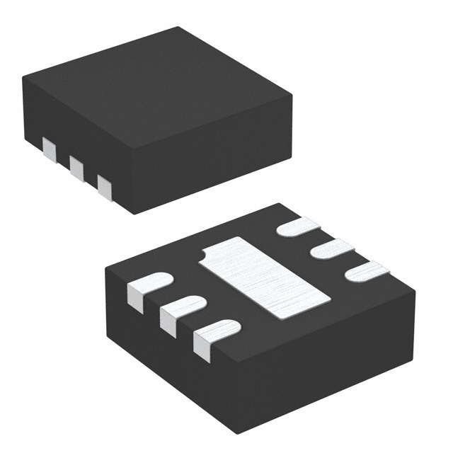
| 供应商器件封装 | 6-TDFN(2x2) |
| 其它名称 | AAT4616AIPUT1 |
| 内部开关 | 是 |
| 包装 | 带卷 (TR) |
| 商标 | Skyworks Solutions, Inc. |
| 安装类型 | 表面贴装 |
| 安装风格 | SMD/SMT |
| 导通电阻—最大值 | 230 mOhms |
| 封装 | Reel |
| 封装/外壳 | 6-WDFN 裸露焊盘 |
| 封装/箱体 | TDFN-22-6 |
| 工作温度 | -40°C ~ 85°C |
| 工作电源电压 | 2.4 V to 5.5 V |
| 工厂包装数量 | 3000 |
| 开关电流—最大值 | 1 uA |
| 开关类型 | 通用 |
| 接口 | 开/关 |
| 最大功率耗散 | 1.18 W |
| 最大工作温度 | + 85 C |
| 最小工作温度 | - 40 C |
| 标准包装 | 3,000 |
| 比率-输入:输出 | 1:1 |
| 特性 | 状态标志 |
| 电压-电源(Vcc/Vdd) | 不需要 |
| 电压-负载 | 2.4 V ~ 5.5 V |
| 电压-输入 | 2.4 V ~ 5.5 V |
| 电流-输出(最大值) | 2A |
| 电流限制 | 可调 |
| 电源电流—最大值 | 10 uA |
| 空闲时间—最大值 | 10 us |
| 类型 | 高端开关 |
| 输入类型 | 非反相 |
| 输出数 | 1 |
| 输出电流 | 2 A |
| 输出端数量 | 1 Output |
| 输出类型 | P 通道 |
| 输出配置 | 高端 |
| 运行时间—最大值 | 7 us |


- 商务部:美国ITC正式对集成电路等产品启动337调查
- 曝三星4nm工艺存在良率问题 高通将骁龙8 Gen1或转产台积电
- 太阳诱电将投资9.5亿元在常州建新厂生产MLCC 预计2023年完工
- 英特尔发布欧洲新工厂建设计划 深化IDM 2.0 战略
- 台积电先进制程称霸业界 有大客户加持明年业绩稳了
- 达到5530亿美元!SIA预计今年全球半导体销售额将创下新高
- 英特尔拟将自动驾驶子公司Mobileye上市 估值或超500亿美元
- 三星加码芯片和SET,合并消费电子和移动部门,撤换高东真等 CEO
- 三星电子宣布重大人事变动 还合并消费电子和移动部门
- 海关总署:前11个月进口集成电路产品价值2.52万亿元 增长14.8%

.jpg)


PDF Datasheet 数据手册内容提取
DATA SHEET AAT4616A: High Precision Adjustable Current Limited Load Switch with Fault Flag Applications Description • USB ports The AAT4616A SmartSwitch is a current-limiting P-channel MOSFET power switch designed for high side load switching • Portable products applications. This switch operates with inputs ranging from 2.4 V • Hot-swap supplies to 5.5 V, making it ideal for both 3 V and 5 V systems. An • Notebook computers integrated current-limiting circuit protects the input supply against large currents that may cause the supply to fall out of • Proprietary peripheral ports regulation. Reverse current blocking is provided to protect the load switch from reverse current potentials while the device is Features shutdown. • Input voltage: 2.4 V to 5.5 V The AAT4616A is also protected from thermal overload which is limited by power dissipation and junction temperatures. The • Programmable over-current limit setting: 300 mA to 1.6 A current limit threshold is programmed with a resistor from SET to • ±10% current limit precision at 750 mA ground and may be adjusted for levels up to 1.6 A. The ultra-fast • Fast transient response: 2 µs response to short circuit current limit response to a sudden short circuit is a mere 2 µs, which reduces the requirements of local supply bypassing. An • Low quiescent current open drain FAULT flag signals an over-current or over- − 10 µA typical while enabled temperature condition after a 4 ms blanking time to prevent false − 1 µA maximum with switch off reporting. Quiescent current is as low as 10 µA and the supply • 130 mΩ typical RDS(ON) current decreases to less than 1 µA in shutdown mode. • Under-Voltage Lockout (UVLO) The AAT4616A is offered in a small Thin, Dual Flat No-Lead • Reverse blocking during disable (TDFN22-6) package. A typical application circuit is shown in Figure 1. The pin configuration is shown in Figure 2. Signal pin • 4 ms fault blanking assignments and functional pin descriptions are provided in • Fault flag open-drain output Table 1. • Active high/low enable options • Over-temperature protection • Temperature range: −40 °C to +85 °C • TDFN (6-pin, 2 x 2 mm) package (MSL1, 260 °C per JEDEC-J-STD-020) Figure 1. AAT4616A Typical Application Circuit Skyworks Solutions, Inc. • Phone [781] 376-3000 • Fax [781] 376-3100 • sales@skyworksinc.com • www.skyworksinc.com 201941E • Skyworks Proprietary Information • Products and Product Information are Subject to Change Without Notice • September 12, 2013 1
DATA SHEET • AAT4616A HIGH PRECISION ADJUSTABLE CURRENT LIMITED LOAD SWITCH WITH FAULT FLAG Figure 2. AAT4616A TDFN22-6 (Top View) Table 1. AAT4616A Signal Descriptions Pin # Name Description Current limiting load switch output (high side P-channel MOSFET drain). Connect a 0.47 µF capacitor from OUT to GND for best 1 OUT load transient response. 2 SET Current limit set pin. Connect a resistor between this pin and ground to program the desired current limit set point. 3 FLT Current limit fault flag pin, open-drain output, active low signal. Pull up with a 10 kΩ to 100 kΩ resistor. 4 ON/ON Load switch enable input. Active high and active low options are available. 5 GND Ground 6 IN Load switch power supply input pin (high side P-channel MOSFET source). Bypass with a 1 µF capacitor from IN to GND. Table 2. AAT4616A Absolute Maximum Ratings (Note 1) Parameter Symbol Minimum Typical Maximum Units IN to GND VIN −0.3 +6.0 V ON/ON,FLT to GND VON, VFLT −0.3 VIN + 0.3 V SET, OUT to GND VSET, VOUT −0.3 VIN + 0.3 V Maximum DC output current (Note 2) IMAX 2 A Operating junction temperature range TJ −40 +150 ºC Storage temperature range TSTG −40 +150 ºC Maximum Soldering Temperature (at leads) TLEAD 300 ºC Thermal resistance θJA 85 ºC/W Power dissipation (Note 3) PD 1.18 W Note 1: Exposure to maximum rating conditions for extended periods may reduce device reliability. There is no damage to device with only one parameter set at the limit and all other parameters set at or below their nominal value. Exceeding any of the limits listed may result in permanent damage to the device. Note 2: The current rating is based on long-term current density limitations. Note 3: Mounted on an FR4 board. Derated 11.8 mW/ ºC above 25 ºC. CAUTION: Although this device is designed to be as robust as possible, Electrostatic Discharge (ESD) can damage this device. This device must be protected at all times from ESD. Static charges may easily produce potentials of several kilovolts on the human body or equipment, which can discharge without detection. Industry-standard ESD precautions should be used at all times. Electrical and Mechanical Specifications Typical performance characteristics of the AAT4616A are illustrated in Figures 3 through 14. The absolute maximum ratings of the AAT4616A are provided in Table 2. The recommended operating conditions are specified in Table 3, and electrical specifications are provided in Table 4. Skyworks Solutions, Inc. • Phone [781] 376-3000 • Fax [781] 376-3100 • sales@skyworksinc.com • www.skyworksinc.com 2 September 12, 2013 • Skyworks Proprietary Information • Products and Product Information are Subject to Change Without Notice • 201941E
DATA SHEET • AAT4616A HIGH PRECISION ADJUSTABLE CURRENT LIMITED LOAD SWITCH WITH FAULT FLAG Table 3. Recommended Operating Conditions Parameter Symbol Minimum Typical Maximum Units Input voltage VIN 2.4 5.5 V High-level Input voltage VON(H) 1.4 V Low-level Input voltage VON(L) 0.5 V Operating temperature TA −40 +85 ºC Table 4. AAT4616A Electrical Specifications (Note 1) (VIN = 5 V, TA = –40 °C to +85 °C [Typical Values are at TA = 25 °C], Unless Otherwise Noted) Parameter Symbol Test Condition Min Typical Max Units Input voltage VIN 2.4 5.5 V Operating quiescent current IQ VIN = 5 V, ON/ON = Active, IOUT = 0 A 10 25 µA Off supply current IQ(OFF) ON/ON = Inactive, VIN = 5.5 V 0.01 1 µA Off switch current ISD(OFF) ON/ON = Inactive, VIN = 5.5 V, VOUT = 0 V 0.01 1 µA Under-Voltage Lockout VUVLO Rising edge, 1% Hysteresis 1.8 2.4 V UVLO hysteresis VUVLO_HYS 10 mV RDS(ON) VIN = 5.0 V, TA = 25 °C 130 180 On resistance mΩ VIN = 3.0 V, TA = 25 °C 150 230 On-resistance temperature coefficient TCRDS 2800 ppm/°C Current limit ILIM RSET = 35 kΩ, VOUT = VIN – 0.5 V 0.67 0.75 0.83 A Minimum current limit ILIM(MIN) 300 mA ON/ON input low voltage VON(L) VIN = 2.4 V to 5.5 V 0.5 V ON/ON input high voltage VON(H) VIN = 2.4 V to 5.5 V 1.4 V ON/ON input leakage ION(SINK) VON = 5.5 V 0.01 1 µA Current limit response time tRESP VIN = 5 V 2 µs Turn-on time tON VIN = 5 V, RLOAD = 10 Ω 4 7 µs Turn-off time tOFF VIN = 5 V, RLOAD = 10 Ω 8 10 µs Fault flag blanking time tBLANK 4 ms Fault flag logic low output VFLT(L) IFLT(SINK) = 1 mA 0.4 V Fault flag logic high leakage current IFLT(SINK) 0.03 1 µA Over-temperature shutdown threshold TSD VIN = 5 V 140 °C Over-temperature shutdown hysteresis TSD_HYS 15 °C Note 1: Performance is guaranteed only under the conditions listed in this Table. Skyworks Solutions, Inc. • Phone [781] 376-3000 • Fax [781] 376-3100 • sales@skyworksinc.com • www.skyworksinc.com 201941E • Skyworks Proprietary Information • Products and Product Information are Subject to Change Without Notice • September 12, 2013 3
DATA SHEET • AAT4616A HIGH PRECISION ADJUSTABLE CURRENT LIMITED LOAD SWITCH WITH FAULT FLAG Typical Performance Characteristics Figure 3. Quiescent Current vs Temperature Figure 4. Current Limit vs Output Voltage (VIN = 5.0 V) (VIN = 5.0 V, TA = 25 °C, RSET = 34.8 kΩ) Figure 5. Quiescent Current Voltage Figure 6. Off-Switch Current vs Temperature (TA = 25 °C) (VIN = 5.0 V) Figure 7. RDS(ON) vs Temperature Figure 8. RSET vs ILIM (TA = 25 °C) Skyworks Solutions, Inc. • Phone [781] 376-3000 • Fax [781] 376-3100 • sales@skyworksinc.com • www.skyworksinc.com 4 September 12, 2013 • Skyworks Proprietary Information • Products and Product Information are Subject to Change Without Notice • 201941E
DATA SHEET • AAT4616A HIGH PRECISION ADJUSTABLE CURRENT LIMITED LOAD SWITCH WITH FAULT FLAG Typical Performance Characteristics Figure 9. ON(ON) Threshold vs Input Voltage Figure 10. AAT4616AIPU-1 Turn-On (RL = 10 Ω, CL = 0.47 µF) Figure 11. Figure 10. AAT4616AIPU-1 Turn-Off Figure 12. Short Circuit Through 0.3 Ω (RL = 10 Ω, CL = 0.47 µF) (VIN = 5.0 V) Figure 13. Output Short Response Figure 14. Fault Blanking Time (VIN = 5.0 V) (VIN = 5.0 V) Skyworks Solutions, Inc. • Phone [781] 376-3000 • Fax [781] 376-3100 • sales@skyworksinc.com • www.skyworksinc.com 201941E • Skyworks Proprietary Information • Products and Product Information are Subject to Change Without Notice • September 12, 2013 5
DATA SHEET • AAT4616A HIGH PRECISION ADJUSTABLE CURRENT LIMITED LOAD SWITCH WITH FAULT FLAG Figure 15. AAT4616A Functional Block Diagram Functional Description typically occurs during device turn-on, but may also occur during a port hot plug-in event. The AAT4616A is ideally suited The AAT4616A is a single channel current limiting load switch for protection of peripheral ports such as USB, RS232, and that is intended to protect against short circuit and over-current parallel ports. events by current limiting to a preset level. This device also provides a reverse current blocking feature, on/off enable Reverse Current Blocking control, and a fault flag to notify a system controller of an over- current, short circuit or over-temperature event. The reverse current blocking feature prevents current flowing from OUT to IN when the device is disabled. When the device is In the event of a load current that exceeds a user-programmed enabled, the electrical characteristics between IN and OUT are current limit level (ILIM), a high speed current limit loop limits still similar to an ideal switch, and current can flow in either the current in a microsecond and resets to low impedance once direction. the short circuit condition is removed. The AAT4616A is internally protected from thermal damage by an over-temperature detection circuit. If the die temperature Application Information reaches the internal thermal limit, the power device is switched Setting Current Limit off until the die temperature cools to a level below the thermal The AAT4616A current limit can be set by an external resistor limit threshold. This device may operate in a thermal cycling (RSET) connected from the SET pin to GND. RSET can be state indefinitely or until the over-current condition is removed. calculated by the following equation: The AAT4616A operates with input voltages ranging from 2.4 V to 5.5 V which, along with its extremely low operating current, make it ideal for battery-powered applications. In cases where the input voltage drops to below 2.4 V, the AAT4616A MOSFET where ILIM is in mA and RSET in kΩ. is protected from entering the saturated region of operation by Table 5 summarizes resistor values for current limit settings. being automatically shut down by the UVLO circuit. Use 1% tolerance metal film resistors to program the desired Current limit or over-temperature conditions are reported by the current limit setting. Figure 16 shows the output current versus open drain FAULT output. A 4 ms blanking interval prevents output voltage with RSET equal to 34.8 kΩ. false reporting during the charging of a capacitive load, which Skyworks Solutions, Inc. • Phone [781] 376-3000 • Fax [781] 376-3100 • sales@skyworksinc.com • www.skyworksinc.com 6 September 12, 2013 • Skyworks Proprietary Information • Products and Product Information are Subject to Change Without Notice • 201941E
DATA SHEET • AAT4616A HIGH PRECISION ADJUSTABLE CURRENT LIMITED LOAD SWITCH WITH FAULT FLAG Table 5. Recommended 1% Tolerance Metal Film Resistors RSET Output Capacitor for Current Limit To ensure stability while the current limit is active, a low RSET (kΩ) Current Limit (mA) capacitance (approximately 0.47 µF) is required. No matter how 86.6 300 large the output capacitor, the output current is limited to the value set by the AAT4616A current limiting circuitry, so very 51 500 large output capacitors can be used. 34.8 750 For example, USB ports are specified to have at least 120 µF of 26.1 1000 capacitance downstream from their controlling power switch. 21.5 1200 The current limiting circuit allows an output capacitance of 18.2 1400 1000 µF or more without disturbing the upstream power supply. 16.5 1600 ON/ON (Enable Input) In many systems, power planes are controlled by integrated circuits that run at lower voltages than the power planes, themselves. The enable input (ON/ON) of the AAT4616A has low and high threshold voltages that accommodate this condition. The threshold voltages are compatible with 5 V TTL and 2.5 V ∼ 5 V CMOS systems. Both active high and active low options are available. Connecting to Capacitive Load When the AAT4616A is switched onto a capacitive load, the device charges the output capacitive load at a rate no greater than the current limit setting. Figure 16. Current Limit vs Output Voltage with 34.8 kΩ RSET FAULT Output Input Capacitor The FAULT Flag FLT is provided to alert the system if an AAT4616A load is not receiving sufficient voltage to operate The input capacitor CIN protects the power supply from current properly. If current limit or over-temperature circuits in any transients generated by the load attached to the AAT4616A. combination are active for more than approximately 4 ms, the When a short circuit is suddenly applied to the output of the FAULT Flag is pulled to ground through an approximately 100 Ω AAT4616A, a large current, limited only by the RDS(ON) of the resistor. MOSFET, flows for less than 1 µs before the current limit circuitry activates. In this event, a moderately sized CIN The filtering of voltage or current transients of less than 4 ms dramatically reduces the voltage transient seen by the power prevents capacitive loads connected to the AAT4616A output supply and by other circuitry upstream from the AAT4616A. from activating the FAULT Flag when they are initially attached. Pull-up resistances of 10 kΩ to 100 kΩ are recommended. The extremely fast short-circuit response time of the AAT4616A Since FLT is an open-drain terminal; it may be pulled up to any reduces the size requirement for CIN. CIN should be located as unrelated voltage less than the maximum operating voltage of close to the device VIN pin as practically possible. Ceramic, 5.5 V, allowing for level shifting between circuits. tantalum, or aluminum electrolytic capacitors are appropriate for CIN. There is no specific capacitor Equivalent Series Resistance (ESR) requirement for CIN. For higher current operation, ceramic capacitors are recommended for CIN due to their inherent capability over tantalum capacitors to withstand input current surges from low impedance sources such as batteries in portable devices. Skyworks Solutions, Inc. • Phone [781] 376-3000 • Fax [781] 376-3100 • sales@skyworksinc.com • www.skyworksinc.com 201941E • Skyworks Proprietary Information • Products and Product Information are Subject to Change Without Notice • September 12, 2013 7
DATA SHEET • AAT4616A HIGH PRECISION ADJUSTABLE CURRENT LIMITED LOAD SWITCH WITH FAULT FLAG Thermal Considerations Note that TJ(MAX) has been replaced by TSD(MIN), the minimum temperature required to activate the over-temperature Since the AAT4616A has internal current limit and over- protection feature of the AAT4616A. With the typical temperature protection, junction temperature is rarely a concern. specification of 140 °C, a safe minimum value to use would be However, if the application requires large currents in a hot 125 °C. environment, it is possible that temperature, rather than current limit, is the dominant regulating condition. In these applications, For example, if an application is specified to operate in 50 °C the maximum current available without risk of an over- environments, the PCB operates at temperatures as high as temperature condition must be calculated. The maximum 85 °C. The application is sealed and its PCB is small, causing internal temperature while the current limit is inactive can be RθJA to be approximately 85 °C/W. Using equation (2): calculated using the following equation: (1) Where: IMAX is the maximum current required by the load. Evaluation Board Information RDS(ON)(MAX) is the maximum rated RDS(ON) of the AAT4616A at The AAT4616A Evaluation Board schematic diagram is provided high temperature. in Figure 17. The PCB layer details are shown in Figure 18, and RθJA is the thermal resistance between the AAT4616A die and Table 6 lists the Evaluation Board Bill of Materials (BOM). the board onto which it is mounted. TA(MAX) is the maximum temperature that the PCB under the AAT4616A would be if the AAT4616A were not dissipating power. Rearranging equation (1) to solve for IMAX: (2) Figure 17. AAT4616A Evaluation Board Schematic Table 6. AAT4616A Evaluation Board Bill of Materials (BOM) Component Part Number Description Manufacturer U1 AAT4616AIPU-T1 Current Limited Load Switch Skyworks C1 GRM188R71C105K Ceramic capacitor, 1 µF, 0603 X7R, 16 V, 10% Murata C2 GRM188R71C474K Ceramic capacitor, 0.47 µF, 0603 X7R, 16 V, 10% Murata RSET Chip Resistor Resistor, 34.8 kΩ, 1/16 W, 1%, 0603 SMD Vishay R2 Chip Resistor Resistor, 100 kΩ, 1/16 W, 1%, 0603 SMD Vishay Skyworks Solutions, Inc. • Phone [781] 376-3000 • Fax [781] 376-3100 • sales@skyworksinc.com • www.skyworksinc.com 8 September 12, 2013 • Skyworks Proprietary Information • Products and Product Information are Subject to Change Without Notice • 201941E
DATA SHEET • AAT4616A HIGH PRECISION ADJUSTABLE CURRENT LIMITED LOAD SWITCH WITH FAULT FLAG Figure 18. AAT4616A Evaluation Board Layer Details Package Information Package dimensions for the TDFN22-6 are shown in Figure 19, and tape and reel dimensions are provided in Figure 20. Skyworks Solutions, Inc. • Phone [781] 376-3000 • Fax [781] 376-3100 • sales@skyworksinc.com • www.skyworksinc.com 201941E • Skyworks Proprietary Information • Products and Product Information are Subject to Change Without Notice • September 12, 2013 9
DATA SHEET • AAT4616A HIGH PRECISION ADJUSTABLE CURRENT LIMITED LOAD SWITCH WITH FAULT FLAG Figure 19. AAT4616A TDFN22-6 Package Dimensions Figure 20. AAT4616A Tape and Reel Dimensions Skyworks Solutions, Inc. • Phone [781] 376-3000 • Fax [781] 376-3100 • sales@skyworksinc.com • www.skyworksinc.com 10 September 12, 2013 • Skyworks Proprietary Information • Products and Product Information are Subject to Change Without Notice • 201941E
DATA SHEET • AAT4616A HIGH PRECISION ADJUSTABLE CURRENT LIMITED LOAD SWITCH WITH FAULT FLAG Ordering Information Marking Manufacturing Part Number Model Name Enable Input Package Evaluation Board Part Number (Note 1) (Note 2) AAT4616A Adjustable Current Limited Active High TDFN22-6 R9XYY AAT4616AIPU-1-T1 AAT4616AIPU-1-EVB Load Switch with Fault Flag Active Low TDFN22-6 U4WBF AAT4616AIPU-T1 AAT4616AIPU-EVB Note 1: XYY = assembly and date code. Note 2: Sample stock is generally held on part numbers listed in BOLD. Copyright © 2013 Skyworks Solutions, Inc. All Rights Reserved. Information in this document is provided in connection with Skyworks Solutions, Inc. (“Skyworks”) products or services. These materials, including the information contained herein, are provided by Skyworks as a service to its customers and may be used for informational purposes only by the customer. Skyworks assumes no responsibility for errors or omissions in these materials or the information contained herein. Skyworks may change its documentation, products, services, specifications or product descriptions at any time, without notice. Skyworks makes no commitment to update the materials or information and shall have no responsibility whatsoever for conflicts, incompatibilities, or other difficulties arising from any future changes. No license, whether express, implied, by estoppel or otherwise, is granted to any intellectual property rights by this document. Skyworks assumes no liability for any materials, products or information provided hereunder, including the sale, distribution, reproduction or use of Skyworks products, information or materials, except as may be provided in Skyworks Terms and Conditions of Sale. THE MATERIALS, PRODUCTS AND INFORMATION ARE PROVIDED “AS IS” WITHOUT WARRANTY OF ANY KIND, WHETHER EXPRESS, IMPLIED, STATUTORY, OR OTHERWISE, INCLUDING FITNESS FOR A PARTICULAR PURPOSE OR USE, MERCHANTABILITY, PERFORMANCE, QUALITY OR NON-INFRINGEMENT OF ANY INTELLECTUAL PROPERTY RIGHT; ALL SUCH WARRANTIES ARE HEREBY EXPRESSLY DISCLAIMED. SKYWORKS DOES NOT WARRANT THE ACCURACY OR COMPLETENESS OF THE INFORMATION, TEXT, GRAPHICS OR OTHER ITEMS CONTAINED WITHIN THESE MATERIALS. SKYWORKS SHALL NOT BE LIABLE FOR ANY DAMAGES, INCLUDING BUT NOT LIMITED TO ANY SPECIAL, INDIRECT, INCIDENTAL, STATUTORY, OR CONSEQUENTIAL DAMAGES, INCLUDING WITHOUT LIMITATION, LOST REVENUES OR LOST PROFITS THAT MAY RESULT FROM THE USE OF THE MATERIALS OR INFORMATION, WHETHER OR NOT THE RECIPIENT OF MATERIALS HAS BEEN ADVISED OF THE POSSIBILITY OF SUCH DAMAGE. Skyworks products are not intended for use in medical, lifesaving or life-sustaining applications, or other equipment in which the failure of the Skyworks products could lead to personal injury, death, physical or environmental damage. Skyworks customers using or selling Skyworks products for use in such applications do so at their own risk and agree to fully indemnify Skyworks for any damages resulting from such improper use or sale. Customers are responsible for their products and applications using Skyworks products, which may deviate from published specifications as a result of design defects, errors, or operation of products outside of published parameters or design specifications. Customers should include design and operating safeguards to minimize these and other risks. Skyworks assumes no liability for applications assistance, customer product design, or damage to any equipment resulting from the use of Skyworks products outside of stated published specifications or parameters. Skyworks, the Skyworks symbol, and “Breakthrough Simplicity” are trademarks or registered trademarks of Skyworks Solutions, Inc., in the United States and other countries. Third-party brands and names are for identification purposes only, and are the property of their respective owners. Additional information, including relevant terms and conditions, posted at www.skyworksinc.com, are incorporated by reference. Skyworks Solutions, Inc. • Phone [781] 376-3000 • Fax [781] 376-3100 • sales@skyworksinc.com • www.skyworksinc.com 201941E • Skyworks Proprietary Information • Products and Product Information are Subject to Change Without Notice • September 12, 2013 11