ICGOO在线商城 > A11-B0-34-615-131-E

 Datasheet下载
- 型号: A11-B0-34-615-131-E
- 制造商: Carling Technologies
- 库位|库存: xxxx|xxxx
- 要求:
| 数量阶梯 | 香港交货 | 国内含税 |
| +xxxx | $xxxx | ¥xxxx |
查看当月历史价格
查看今年历史价格
A11-B0-34-615-131-E产品简介:
ICGOO电子元器件商城为您提供A11-B0-34-615-131-E由Carling Technologies设计生产,在icgoo商城现货销售,并且可以通过原厂、代理商等渠道进行代购。 提供A11-B0-34-615-131-E价格参考以及Carling TechnologiesA11-B0-34-615-131-E封装/规格参数等产品信息。 你可以下载A11-B0-34-615-131-E参考资料、Datasheet数据手册功能说明书, 资料中有A11-B0-34-615-131-E详细功能的应用电路图电压和使用方法及教程。
| 参数 | 数值 |
| 品牌 | Carling Technologies |
| 产品目录 | |
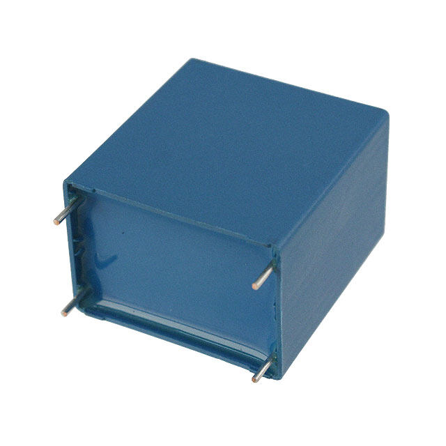
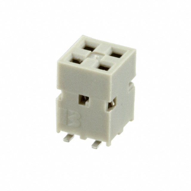
| 描述 | 断路器 15A 1 POLE .250 QC FLAT ROCKER RED |
| 产品分类 | 断路器与附件 |
| 产品手册 | |
| 产品图片 |
|
| rohs | 符合RoHS |
| 产品系列 | 断路器,Carling Technologies A11-B0-34-615-131-E |
| mouser_ship_limit | 该产品可能需要其他文档才能发货到中国。 |
| 产品型号 | A11-B0-34-615-131-E |
| 产品 | Hydraulic Magnetic Circuit Breakers |
| 产品种类 | |
| 产品类型 | Supplementary Protector / Motor Controller |
| 介质强度 | 1.5 V |
| 商标 | Carling Technologies |
| 安装风格 | Threaded Stud |
| 宽度 | 19.18 mm |
| 工作温度范围 | - 40 C to + 85 C |
| 工厂包装数量 | 10 |
| 执行器类型 | Rocker |
| 极数 | 1 Pole |
| 照明 | Not Illuminated |
| 电压额定值 | 277 VAC, 80 VDC |
| 电压额定值AC | 277 V |
| 电压额定值DC | 80 V |
| 电流额定值 | 15 A |
| 电路功能 | Series Trip (Current) |
| 端接类型 | Screw |
| 类型 | Circuit Breakers |
| 系列 | A |
| 跳闸时间 | 0.6 s to 20 s |
| 长度 | 50.8 mm |
| 颜色 | White |


- 商务部:美国ITC正式对集成电路等产品启动337调查
- 曝三星4nm工艺存在良率问题 高通将骁龙8 Gen1或转产台积电
- 太阳诱电将投资9.5亿元在常州建新厂生产MLCC 预计2023年完工
- 英特尔发布欧洲新工厂建设计划 深化IDM 2.0 战略
- 台积电先进制程称霸业界 有大客户加持明年业绩稳了
- 达到5530亿美元!SIA预计今年全球半导体销售额将创下新高
- 英特尔拟将自动驾驶子公司Mobileye上市 估值或超500亿美元
- 三星加码芯片和SET,合并消费电子和移动部门,撤换高东真等 CEO
- 三星电子宣布重大人事变动 还合并消费电子和移动部门
- 海关总署:前11个月进口集成电路产品价值2.52万亿元 增长14.8%


PDF Datasheet 数据手册内容提取
A-Series A-Series CIRCUIT BREAKER Well known for their proven reliability, Carling Technologies’ A-Series hydraulic magnetic circuit breakers are compact, temperature stable and designed for precision operation in OEM markets requiring general purpose as well as full load amp applications. When front panel operation and aesthetics demand a clean, contemporary design, the visi-rocker or paddle actuators are ideally suitable. A sealed toggle actuator style is also available and ideal for harsh environment applications requiring additional sealing protection. Optional rocker-guard and push- to-reset bezels, which help prevent inadvertent actuation, are also available. 1-6 poles; ratings from 0.02 to 50 amps, up to 277VAC or 80VDC; UL Recognized, UL Listed, UL1500, UL1077, TUV, VDE & CSA Product Highlights: Typical Applications: Up to 50 amps in a compact size Telecom/Datacom Various actuator styles Marine Sealed metal toggle option tested to Military MIL-PRF-55629C. Meets IP68 Renewable Energy Requirements Generators & Welder Carling Technologies, Inc. 60 Johnson Avenue, Plainville, CT 06062 Email: sales@carlingtech.com www.carlingtech.com Application Support: team2@carlingtech.com Phone: 860.793.9281 Fax: 860.793.9231
2 | A-Series Circuit Breaker - General Specifications Electrical Mechanical Maximum Voltage 277VAC 50/60 Hz, 80VDC Endurance 10,000 ON-OFF operations @ 6 per Current Ratings Standard current coils: 0.100, minute; with rated Current & Voltage. 0.250, 0.500, 0.750, 1.00, 2.50, Trip Free All A-Series Circuit Breakers will trip 5.00, 7.50, 10.0, 15.0, 20.0, 25.0, on overload, even when the actuator 30.0, 35.0, 40.0, 50.0. Other ratings is forcibly held in the ON position. available - consult ordering Trip Indication The operating actuator moves scheme. positively to the OFF position when Standard Voltage Coils DC-6V, 12V; AC-120V, Other ratings an overload causes the circuit available, consult ordering scheme. breaker to trip. When mid-trip Auxiliary Switch Rating SPDT; 10.1 A - 250VAC, handle is specified, the handle 1.0 A-65VDC/0.5 A - 80 VDC, moves to the mid position on 0.1A - 125VAC (with gold contacts). electrical trip of the circuit breaker. Insulation Resistance Minimum: 100 Megohms at 500 When mid-trip handle with alarm VDC switch is specified, the handle Dielectric Strength UL, CSA - 1500V 60 Hz for one moves to the mid position & the minute between all electrically alarm switch actuates when the isolated terminals. A-Series rocker circuit breaker is electrically tripped. circuit breakers comply with the 8mm spacing & 3750V dielectric Physical requirements from hazardous Number of Poles 1 - 6 Poles (handle) and 1-3 poles voltage to operator accessible (rocker) at 30 Amps or less. 1 and 2 surfaces per EN 60950 and VDE poles at 31 Amps thru 50 Amps. 0805. Internal Circuit Config. Series, (with or without auxiliary Resistance, Impedance Values from Line to Load Terminal switch), Shunt and Relay with current - based on Series Trip Circuit or voltage trip coils, Dual Coil, Breaker. Switch Only with or without auxiliary RESISTANCE PER POLE VALUES switch. from Line to Load Terminals Weight Approximately 65 grams/pole. (Values Based on Series Trip Circuit Breaker) (Approximately 2.32 ounces/pole) CURRENT TOLERANCE Standard Colors Housing - Black; Actuator- See (AMPS) (%) Ordering Scheme. 0.10 - 5.0 15 Environmental 5.1 - 20.0 25 Designed and tested in accordance with requirements of 20.1 - 50.0 35 specification MIL-PRF-55629 & MIL-STD-202 as follows: Shock Withstands 100 Gs, 6ms, sawtooth while carrying rated current per Method 213, Test Condition “I”. Instantaneous and ultra-short curves tested @ 90% of rated current. Vibration Withstands 0.060” excursion from 10-55 Hz, and 10 Gs 55-500 Hz, at rated current per Method 204C, Test Condition A. Instantaneous and ultrashort curves tested at 90% of Pulse Tolerance Curves rated current. Moisture Resistance Method 106D; ten 24-hour cycles @ + 25°C to +65°C, 80-98% RH.56 days @ +85°C, 85% RH. Salt Spray Method 101, Condition A (90-95% RH @ 5% NaCl Solution, 96 hrs). Thermal Shock Method 107D, Condition A (Five cycles @ -55°C to +25°C to +85°C to +25°C). Operating Temperature -40° C to +85° C *Manufacturer reserves the right to change product specification without prior notice. Email: sales@carlingtech.com Application Support: team2@carlingtech.com Phone: (860) 793–9281 Fax: (860) 793–9231 www.carlingtech.com
A-Series Circuit Breaker - General Specifications | 3 Electrical Tables Table A: Lists UL Recognized & CSA Accepted configurations and performance capabilities as a Component Supplementary Protector. A-SERIES TABLE A: COMPONENT SUPPLEMENTARY PROTECTORS Voltage Current Rating Short Circuit Capacity (Amps) Application Codes Circuit General UL / CSA Construction Configuration Max Frequency Phase Full Load Purpose With Backup Without Notes Rating Amps UL CSA Amps Fuse Backup Fuse 32 DC --- 0.02 - 15 --- --- 5000 TC1, OL1, U2 TC1, OL1, U2 65 DC --- 31 - 50 --- --- 7500 TC1, 2, OL1, U1 TC1, 2, OL1, U1 0.02 - 30 --- --- 7500 TC1, 2, OL1, U1 TC1, 2, OL1, U1 80 DC --- --- 31 - 50 --- 7500 TC1, 2, OL0, U1 TC1, 2, OL0, U1 125 50 / 60 1 0.02 - 30 --- --- 3000 TC1, OL1, U2 TC1, OL1, U2 Rocker Version 125 50 / 60 1 1 - 50 --- --- 2000 TC1, OL1, U2 TC1, OL1, U2 125 50 / 60 1 4 1 - 50 --- --- 1000 TC1, OL1, U2 TC3, OL1, U3 125 / 250 50 / 60 1 3 0.02 - 30 --- --- 3000 TC1, 2, OL1, U2 TC1, 2, OL1, U2 Rocker Version Series 125 / 250 50 / 60 1 3 0.02 - 50 --- --- 3000 TC1, 2, OL1, U2 TC1, 2, OL1, U2 Handle 0.02 - 30 --- --- 1500 TC1, 2, OL0, U2 TC1, 2, OL0, U2 Single Pole Break 1 0.02 - 30 --- --- 3000 TC1, OL1, U2 TC1, OL1, U2 Two Pole Break --- --- 3000 TC1, 2, OL0, U1 TC1, 2, OL0, U1 250 50 / 60 1 4 1 - 50 --- --- 1000 TC1, OL1, U2 TC3, OL1, U3 0.02 - 30 --- 5000 2 --- TC1, 2, OL1, C1 TC1, 2, OL1, C1 3 31 - 50 --- 2000 1 --- TC1, 2, OL1, C1 TC1, 2, OL1, C1 277 50 / 60 1 0.02 - 30 --- 5000 1 --- TC1, 2, OL1, C1 TC1, 2, OL1, C1 32 DC --- 0.02 - 50 --- --- 5000 TC1, OL1, U2 TC1, OL1, U2 65 DC --- 0.02 - 50 --- --- 7500 TC1, 2, OL1, U1 TC1, 2, OL1, U1 0.02 - 30 --- --- 7500 TC1, 2, OL1, U1 TC1, 2, OL1, U1 80 DC --- --- 31 - 50 --- 7500 TC1, 2, OL0, U1 TC1, 2, OL0, U1 0.02 - 30 --- --- 3000 TC1, OL1, U2 TC1, OL1, U2 Rocker Version 125 50 / 60 1 1 - 50 --- --- 2000 TC1, OL1, U2 TC1, OL1, U2 125 50 / 60 1 4 0.02 - 30 --- --- 1000 TC1, OL1, U2 TC3, OL1, U3 125 / 250 50 / 60 1 3 0.02 - 30 --- --- 3000 TC1, 2, OL1, U1 TC1, 2, OL1, U1 Rocker Version Dual Coil 125 / 250 50 / 60 1 3 0.02 - 50 --- --- 3000 TC1, 2, OL1, U2 TC1, 2, OL1, U2 1 0.02 - 30 --- --- 1500 TC1, OL0, U2 TC1, OL0, U2 Single Pole Break 1 0.02 - 30 --- --- 3000 TC1, OL1, U2 TC1, OL1, U2 Two Pole Break 1 --- 31 - 50 --- 3000 TC1, 2, OL0, U1 TC1, 2, OL0, U1 250 50 / 60 1 4 1 - 50 --- --- 1000 TC1, OL1, U2 TC3, OL1, U3 0.02 - 30 --- 5000 2 --- TC1, 2, OL1, C1 TC1, 2, OL1, C1 3 31 - 50 --- 2000 1 --- TC1, 2, OL1, C1 TC1, 2, OL1, C1 277 50 / 60 1 0.02 - 30 --- 5000 1 --- TC1, 2, OL1, U1 TC1, 2, OL1, U1 80 DC --- 0.02 - 30 --- --- 7500 TC1, 2, OL1, U1 TC1, 2, OL1, U1 125 / 250 50 / 60 1 0.02 - 30 --- --- 3000 TC1, 2, OL1, U1 TC1, 2, OL1, U1 Shunt 1 0.02 - 30 --- --- 3000 TC1, 2, OL1, U1 TC1, 2, OL1, U1 250 50 / 60 3 0.02 - 30 --- 5000 2 --- TC1, 2, OL1, C1 TC1, 2, OL1, C1 277 50 / 60 1 0.02 - 30 --- 5000 1 --- TC1, 2, OL1, C1 TC1, 2, OL1, C1 80 DC --- 0.02 - 30 --- --- 7500 TC1, 2, OL1, U1 TC1, 2, OL1, U1 125 / 250 50 / 60 1 3 0.02 - 30 --- --- 3000 TC1, 2, OL1, U1 TC1, 2, OL1, U1 Relay 1 0.02 - 30 --- --- 3000 TC1, 2, OL1, U1 TC1, 2, OL1, U1 250 50 / 60 3 0.02 - 30 --- 5000 2 --- TC1, 2, OL1, C1 TC1, 2, OL1, C1 277 50 / 60 1 0.02 - 30 --- 5000 1 --- TC1, 2, OL1, C1 TC1, 2, OL1, C1 65 DC --- 0.02 - 50 --- 80 DC --- 0.02 - 30 --- Switch Only 1 --- 31 - 50 not applicable 250 50 / 60 3 0.02 - 50 --- 277 50 / 60 1 0.02 - 30 31 - 50 Notes: 1 Requires branch circuit backup with a UL LISTED Type K5 or RK5 fuse (15A minimum) at no more than 4 times the rating of the protector. 2 Same as note 1, except that backup fuse is limited to 80 A maximum. 3 2 pole protector required (with one pole per power line) for: 125/250 VAC, 1 pole protector required for : 125 VAC, 1Ø Power System. 4 Satisfies the requirements of clause 11.2.8.2.5 of CSA STD C22.2 No 100 for the use of supplementary protectors with portable generators. Email: sales@carlingtech.com Application Support: team2@carlingtech.com Email: sales@carlingtech.com Application Support: team2@carlingtech.com Phone: (860) 793–9281 Fax: (860) 793–9231 www.carlingtech.com Phone: (860) 793–9281 Fax: (860) 793–9231 www.carlingtech.com
4 | A-Series Circuit Breaker - General Specifications Electrical Tables Table B: Lists UL Recognized, CSA Accepted, VDE & TUV Certified configurations & performance capabilities as a Component Supplementary Protector. 1 3 2 3 2 3 2 Notes: 1 General Purpose Ratings for UL/CSA Only. 2 Requires branch circuit backup with a UL LISTED Type K5 or RK5 fuse (15A minimum) at no more than 4 times the rating of the protector. 3 Same as note 2, except that backup fuse is limited to 80 A maximum. 4 Satisfies the requirements of clause 11.2.8.2.5 of CSA STD C22.2 No 100 for the use of supplementary protectors with portable generators. Email: sales@carlingtech.com Application Support: team2@carlingtech.com Phone: (860) 793–9281 Fax: (860) 793–9231 www.carlingtech.com
A-Series Circuit Breaker - General Specifications | 5 Electrical Tables Table C: Lists UL Recognized, CSA Accepted configurations and performance capabilities as Protectors, Supplementary for Marine Electrical and Fuel Systems (Guide PEQZ2, File E75596). Ignition Protected per UL 1500. UL Classified Small Craft Electrical Devices, Marine in accordance with ISO 8846 (Guide UZMK, File MQ1515) as Marine Supplementary Protectors. A-SERIES TABLE C: UL1500 (Marine Ignition Protected) CURRENT SHORT CIRCUIT VOLTAGE APPLICATION CODES RATING CAPACITY (AMPS) CIRCUIT CONFIGURATION WITHOUT BACKUP MAX. RATING FREQUENCY PHASE FULL LOAD AMPS UL CSA FUSE SERIES 14 1 DC --- 0.02 - 50 5000 TC1,OL1,U1 TC1,OL1,U1 32 1 DC --- 0.02 - 50 5000 TC1,OL1,U2 TC1,OL1,U2 65 DC --- 0.02 - 50 3000 TC1,OL1,U1 TC1,OL1,U1 125 50 / 60 1 0.02 - 50 3000 TC1,OL1,U2 TC1,OL1,U2 125 / 250 50 / 60 1 2 0.02 - 50 3000 TC1,OL1,U2 TC1,OL1,U2 250 50 / 60 1 0.02 - 30 1500 TC1,OL1,U1 TC1,OL1,U1 Notes: 1 Available witNh ospteesci:al catalog number only (consult factory). 2 2 pole protector req1uiArevda (iwlaitbh loen we ipther Spopweecri alinl eC) afotar 1lo2g5 /N 2u5m0 VbAeCr .O 1n ployl e( cporontescutlot rf raecqtuoirreyd) for 125 VAC 1 phase power system 22 pole protector required (with one per power line) for 125 / 250 VAC. 1 pole protector required for 125 VAC 1 phase power system Table D: Lists UL Listed configurations and performance capabilities as Circuit Breakers for use in Communications Equipment (Guide DITT, File E189195), under UL489A. Notes: 1 Parallel Pole Construction Agency Certifications UL Recognized CSA Accepted Component Supplementary UL Standard 1077 Component Recognition Program Protector under Class 3215 30, as Protectors Supplementary File 047848 0 000 CSA (Guide CCN/QVNU2, File E75596) Standard C22.2 No. 235 UL Standard 508 Switches, Industrial Control TUV Certified EN60934, under License No. (Guide CCN/NRNT2, File E148683) R72103448 UL Standard 1500 Protectors, Supplementary for Marine Electrical & Fuel Systems VDE Certified EN60934, VDE 0642 under File (Guide PEQZ2, File E75596) No. 10537 Ignition Protection UL Listed UL Standard 489A Communications Equipment (Guide CCN/DITT, File E189195) Email: sales@carlingtech.com Application Support: team2@carlingtech.com Email: sales@carlingtech.com Application Support: team2@carlingtech.com Phone: (860) 793–9281 Fax: (860) 793–9231 www.carlingtech.com Phone: (860) 793–9281 Fax: (860) 793–9231 www.carlingtech.com
6 | A-Series Circuit Breaker - Handle UL Recognized – Ordering Scheme A A 3 B 0 10 450 1 B 1 C 1 2 3 4 5 6 7 8 9 10 11 Series Actuator Poles Circuit Aux/Alarm Frequency Current Rating Terminal Actuator Mounting/ Agency Switch & Delay Color Barriers Approval 1 SERIES 7 CURRENT RATING (AMPERES) A CODE AMPERES 020 0.020 225 0.250 420 2.000 611 11.000 025 0.025 230 0.300 522 2.250 711 11.500 2 ACTUATOR 1 030 0.030 235 0.350 527 2.750 612 12.000 A Handle, one per pole 035 0.035 240 0.400 430 3.000 712 12.500 B Handle, one per multipole unit 040 0.040 245 0.450 435 3.500 613 13.000 S Mid-Trip Handle, one per pole 045 0.045 250 0.500 440 4.000 614 14.000 T Mid-Trip Handle, one per pole & Alarm Switch 050 0.050 255 0.550 445 4.500 615 15.000 055 0.055 260 0.600 450 5.000 616 16.000 060 0.060 265 0.650 455 5.500 617 17.000 3 POLES 065 0.065 270 0.700 460 6.000 618 18.000 1 One 3 Three 5 Five 070 0.070 275 0.750 465 6.500 620 20.000 2 Two 4 Four 6 Six 075 0.075 280 0.800 470 7.000 622 22.000 080 0.080 285 0.850 475 7.500 624 24.000 085 0.085 290 0.900 480 8.000 625 25.000 4 CIRCUIT 090 0.090 295 0.950 485 8.500 630 30.000 A 2 Switch Only (No Coil) F 3 Relay Trip (Current) 095 0.095 410 1.000 490 9.000 635 8 35.000 B Series Trip (Current) G 3 Relay Trip (Voltage) 210 0.100 512 1.250 495 9.500 640 8 40.000 DC 3 SSehruienst TTrriipp ((CVuorlrtaegnet)) H 3,4 DVoulatal gCeo iCl woiilth Shunt Trip 221250 00..125000 451157 11..570500 671100 1100..050000 664550 88 4550..000000 E 3 Shunt Trip (Voltage) K 3,4 Dual Coil with Relay Trip OR VOLTAGE COIL (NORMAL RATED VOLTAGE) 6 Voltage Coil CODE AMPERES A06 6 DC A32 32 DC J12 12 AC J65 65 AC A12 12 DC A48 48 DC J18 18 AC K20 120 AC 5 AUXILIARY / ALARM SWITCH 5 5 S.P.S.T., 0.093 Q.C. Term. A18 18 DC A65 65 DC J24 24 AC L40 240 AC 0 without Aux Switch (Gold Contacts) A24 24 DC J06 6 AC J48 48 AC 1 S.P.D.T., 0.093 Q.C. Term. 7 S.P.S.T., 0.110 Q.C. Term. 2 S.P.D.T., 0.110 Q.C. Term. (Gold Contacts) 4 S.P.D.T., 0.110 Q.C. Term. 8 S.P.S.T., 0.187 Q.C. Term. 8 TERMINAL 9 (Gold Contacts) 9 S.P.D.T., 0.187 Q.C. Term. 1 10 Push-On 0.250 Tab (Q.C.) E 11 Screw M4 (Bus Type) 2 Screw 8-32 with upturned lugs F Screw M5 with upturned lugs 3 11 Screw 8-32 (Bus Type) & 30° bend 4 Screw 10-32 with upturned lugs G Screw M5 (Bus Type) & 30° bend 6 FREQUENCY & DELAY 5 11 Screw 10-32 (Bus Type) H 11 Screw M5 (Bus Type) 03 DC 50/60Hz, Switch Only 30 DC, 50/60Hz Instantaneous 6 Screw 8-32 with upturned lugs L 12 0.250 Q.C./ Solder Lug 10 DC Instantaneous 31 DC, 50/60Hz Ultra Short & 30° bend M 11 M6 Threaded Stud 11 DC Ultra Short 32 DC, 50/60Hz Short 7 Screw 8-32 (Bus Type) Q 14 Push-In Stud 12 DC Short 34 DC, 50/60Hz Medium & 30° bend R Screw M4 with upturned lugs 11222224601246 DD5555500000CC/////66666 ML00000oHHHHHendzzzzzgi uIUSMLnmohlestnrotdaagri tunSmtahnoertous 44555344624662 777777 555DDDD000CCCC///666,,,, 000SML5HHHo0hen/ozzzd6g ri0S tu,ML, HHhmHoezoini,-d- r IgLIHtnin,u,o r irHm-HunuInsigsi,-- hrIhIHnun rsir-uuhInss hrhu sh CB9 8 SSS&S&ccc c 33rrrreee0e0www°w° bb MM11ee00nn45--dd 33ww 22ii tt(whhB iuutuhpps ttu uuTprrynntpueeerddn) ell uudgg lssu gs SPT 111133 &PPS& urc 33irnse00htew°°- dObb M eenCnn4 i0rdd c(. B1u1uit0 sB TToayabpr de(Q )T e.Crm.)inals Notes: 1 Actuator Code: 9 ACTUATOR COLOR & LEGEND A: Handle tie pin spacer(s) and retainers provided un-assembled with multi-pole units. Actuator Color I-O ON-OFF Dual Legend Color B: Handle location as viewed from front of breaker: White A B 1 Black 2 pole - left pole 3 pole - center pole 4 pole - two handles at center poles Black C D 2 White 5 pole - three handles at center poles 6 pole - four handles at center poles Red F G 3 White S: Handle moves to mid-position only upon electrical trip of the breaker. Available with Green H J 4 White circuit codes B, C, D, E, F, G, H and K. Blue K L 5 White T: Handle moves to mid-position and alarm switch activates only upon electrical trip of the Yellow M N 6 Black breaker. Available with circuit codes B & C. 2 Switch Only circuits, rated up to 50 amps and 6 poles, and only available when tied to a Gray P Q 7 Black protected pole (Circuit Code B, C, D or H.), For .02 to 30 amps, Orange R S 8 Black select Current Code 630. For 35 - 50 amps, select Current Code 650. Black (short handle)15 T U 9 White 3 Available with terminal Codes 1, 2 and 3. Current Rating limited to 50A amps maximum. 4 Consult factory for available Dual Coil options, as special catalog number is required. With Shunt construction, Dual Coils will trip instantaneously on line voltage. Dual coils 10 MOUNTING / BARRIERS require 30VA minimum power to trip and are rated for intermittent duty only. MOUNTING STYLE BARRIERS 5 Auxiliary Switch breakers with Series Trip & Switch Only circuits: ≤ 30A - supplied with standard half shells. 35-50A - supplied with extended boat (B-Style) half shells. Threaded Insert, 2 per pole On multi-pole breakers, one auxiliary switch is supplied, mounted in the extreme right pole. 1 6-32 x 0.195 inches no 6 Separate pole type voltage coils not rated for continuous duty. Available only with delay A 6-32 x 0.195 inches yes codes 10 and 20. 2 ISO M3 x 5mm no 7 Available with Circuit Codes B & D only. VDE Certified to 30 amps. UL Recognized, CSA B ISO M3 x 5mm (multipole only) yes Accepted & TUV Certified to 50 amps. 8 VDE Certification available with single pole breakers with DC Delay only. UL Recognition Front panel Snap-In, 0.75” wide bezel and CSA Accepted available in one and two pole breakers. 5 without Handleguard no 9 Screw Terminals are recommended on ratings greater than 20 amps. Ratings over 30 6 without Handleguard (multipole only) yes amps are only available with Terminal Codes 5, 9, G, H, M and Q.. Front panel Snap-In, 0.96” wide bezel 10 Terminal Code 1: VDE Certification up to 25 amps and UL Recognition and CSA 7 without Handleguard, 1-pole 0.96” wide; no Certification up to 30 amps, but not recommended over 20 amps. 11 Terminal Codes 3, 5, E and H (Bus Type) with VDE, are supplied with Lock Washers, multipole units have .105” bezel overhang on all sides and Terminal Code M (M6 Threaded Stud) with VDE is supplied with Lock and Flat 8 without Handleguard, 1-pole 0.96” wide; yes Washers. These breakers are only VDE Certified when the washers are used. (multipole only) .105” bezel overhang on all sides 12 Terminal Code L: VDE Certified available up to 12A. UL Recognized & CSA Accepted available up to 30A. 13 Single pole breakers with Terminal Code P (Printed Circuit Board) are available up to 30 amps with VDE Certification and 50 amps with UL Recognition and CSA Accepted, with Circuit 11 AGENCY APPROVAL Codes A, B and C. Two pole breakers with Terminal Code P (Printed Circuit Board) are C UL Recognized & CSA Accepted available up to 40 amps with UL Recognition and CSA Accepted with Circuit Codes A, B and C. D VDE Certified, UL Recognized & CSA Accepted 14 Terminal Code Q not available with VDE certification. 15 Single pole only. E TUV Certified, UL Recognized & CSA Accepted I UL Recognized STD 1077, UL Recognized 1500 (ignition protected), & CSA Accepted Email: sales@carlingtech.com Application Support: team2@carlingtech.com Phone: (860) 793–9281 Fax: (860) 793–9231 www.carlingtech.com
A-Series Circuit Breaker - Handle UL489A – Ordering Scheme | 7 A A 1 B 0 14 450 1 B 1 M T 1 2 3 4 5 6 7 8 9 10 11 12 Series Actuator Poles Circuit Aux/Alarm Frequency Current Rating Terminal Actuator Mounting/ Max. Appl. Agency Switch & Delay Color Barriers Rating Approval 1 SERIES 9 ACTUATOR COLOR & LEGEND A Actuator Color ON-OFF Dual Legend Color White B 1 Black Black D 2 White 2 ACTUATOR 1 Red G 3 White A Handle, one per pole Green J 4 White S Mid-Trip Handle, one per pole Blue L 5 White T Mid-Trip Handle, one per pole & Alarm Switch Yellow N 6 Black Gray Q 7 Black Orange S 8 Black 3 POLES 2 Black (short handle) 10 U 9 White 1 One 2 Two 3 Three 10 MOUNTING / BARRIERS 4 Four MOUNTING STYLE BARRIERS Threaded Insert, 2 per pole 1 6-32 x 0.195 inches no 4 CIRCUIT A 6-32 x 0.195 inches yes B Series Trip (Current) 2 ISO M3 x 5mm no B ISO M3 x 5mm (multipole only) yes Front panel Snap-In, 0.75” wide bezel 5 AUXILIARY/ALARM SWITCH 2 7 S.P.S.T., 0.110 Q.C. Term. 5 without Handleguard no 0 without Aux Switch (Gold Contacts) 6 without Handleguard (multipole only) yes 1 S.P.D.T., 0.093 Q.C. Term. 8 S.P.S.T., 0.187 Q.C. Term. Front panel Snap-In, 0.96” wide bezel 2 S.P.D.T., 0.110 Q.C. Term. 9 S.P.D.T., 0.187 Q.C. Term. 7 without Handleguard, 1-pole 0.96” wide; no multipole units have .105” bezel overhang on all sides 8 without Handleguard, 1-pole 0.96” wide; yes 6 FREQUENCY & DELAY (multipole only) .105” bezel overhang on all sides 11 DC Ultra Short 52 3 DC, Short,Hi-Inrush 12 DC Short 54 3 DC, Medium, Hi-Inrush 14 DC Medium 56 3 DC, Long, Hi-Inrush 11 MAXIMUM APPLICATION RATING 16 DC Long M 80 DC 7 CURRENT RATING (AMPERES) 12 AGENCY APPROVAL CODE AMPERES T UL489A Listed 210 0.100 285 0.850 455 5.500 613 13.000 K UL489A Listed, VDE Certified 215 0.150 290 0.900 460 6.000 614 14.000 J UL489A Listed, TUV Certified 220 0.200 295 0.950 465 6.500 615 15.000 225 0.250 410 1.000 470 7.000 616 16.000 230 0.300 512 1.250 475 7.500 617 17.000 Notes: 235 0.350 415 1.500 480 8.000 618 18.000 1 Actuator Code: 240 0.400 517 1.750 485 8.500 620 20.000 A: Handle tie pin spacer(s) and retainers provided un-assembled with multi-pole units. 245 0.450 420 2.000 490 9.000 622 22.000 S: Handle moves to mid-position only upon electrical trip of the breaker. 250 0.500 522 2.250 495 9.500 624 24.000 T: Handle moves to mid-position and alarm switch activates only upon electrical trip of the 255 0.550 527 2.750 610 10.000 625 25.000 breaker. 260 0.600 430 3.000 710 10.500 630 30.000 2 On multi-pole breakers, one auxiliary switch is supplied, mounted in the extreme right pole. 265 0.650 435 3.500 611 11.000 635 3 35.000 3 VDE Certified to 30 amps. UL489A Listed to 50 amps. 270 0.700 440 4.000 711 11.500 640 3 40.000 4 VDE Certification available with single pole breakers only. UL489A Listing available with one 227850 00..785000 444550 45..500000 671122 1122..050000 664550 33 4550..000000 5 aSanrcedr e otwwn loyT eparovmaleiinl ababrlesle aa kwreeitr hrse .Tceormmmineanl Cdeodd eosn 5ra, t9in Ggs, Hgr, eMa taenr dth Qan. 20 amps. Ratings over 30 amps 6 Terminal Code 1 (Push-On) available up to 25 amps with VDE Certification and 30 amps with UL489A Listing, but is not recommended over 20 amps. 8 TERMINAL 5 7 Terminal Codes 3, 5 and H (Bus Type) with VDE, are supplied with Lock Washers, and 12 6 PSucrsehw-O 8n-3 02. 2w5i0th T uapbt u(Qrn.eCd.) l ugs 9 S&c 3re0w° b 1e0n-d32 (Bus Type) 8 TTSehinremgsleien apblor eCleao kbdereer saM ka er(eMrs o6 wn Tliythh rV eTDearEdme Cdine aSrltt iuCfideo)dd w ewi tPhhe (VnPD rthiEnet e iswd sa Cuspihrcpeulriseit daB rwoeai tuhrds Le) odac.r ek aavnadi lFalbalte W upa stohe rs. 3 7 Screw 8-32 (Bus Type) B Screw M5 with upturned lugs 30 amps with VDE Certification and 50 amps with UL489A Listing. 4 Screw 10-32 with upturned lugs F Screw M5 with upturned lugs 9 Terminal Code Q not available with VDE certification. 5 7 Screw 10-32 (Bus Type) & 30° bend 10 Single pole only. 6 Screw 8-32 with upturned lugs G Screw M5 (Bus Type) & 30° bend & 30° bend H Screw M5 (Bus Type) 7 Screw 8-32 (Bus Type) M 7 M6 Threaded Stud & 30° bend P 8 Printed Circuit Board Terminals 8 Screw 10-32 with upturned lugs Q 9 Push-In Stud & 30° bend Email: sales@carlingtech.com Application Support: team2@carlingtech.com Email: sales@carlingtech.com Application Support: team2@carlingtech.com Phone: (860) 793–9281 Fax: (860) 793–9231 www.carlingtech.com Phone: (860) 793–9281 Fax: (860) 793–9231 www.carlingtech.com
8 | A-Series Circuit Breaker - Handle WORLD – Ordering Scheme A A 3 B 0 14 450 1 A 1 P 1 2 3 4 5 6 7 8 9 10 11 Series Actuator Poles Circuit Aux/Alarm Frequency Current Rating Terminal Actuator Mounting/ Agency Switch & Delay Color Barriers Approval 1 SERIES 8 TERMINAL 9 A 1 10 Push-On 0.250 Tab (Q.C.) B Screw M5 with upturned lugs 2 Screw 8-32 with upturned lugs C Screw M4 with upturned lugs 3 11 Screw 8-32 (Bus Type) E 11 Screw M4 (Bus Type) 2 ACTUATOR 1 4 Screw 10-32 with upturned lugs F Screw M5 with upturned lugs A Handle, one per pole 5 11 Screw 10-32 (Bus Type) & 30° bend B Handle, one per multipole unit 6 Screw 8-32 with upturned lugs G Screw M5 (Bus Type) & 30° bend S Mid-Trip Handle, one per pole & 30° bend H 11 Screw M5 (Bus Type) T Mid-Trip Handle, one per pole & Alarm Switch 7 Screw 8-32 (Bus Type) R Screw M4 with upturned lugs & 30° bend & 30° bend 3 POLES 8 Screw 10-32 with upturned lugs T 11 Screw M4 (Bus Type) 1 One 3 Three 5 Five & 30° bend & 30° bend 2 Two 4 Four 6 Six 9 Screw 10-32 (Bus Type) & 30° bend 4 CIRCUIT A 2 Switch Only (No Coil) D 3 Shunt Trip (Current) 9 ACTUATOR COLOR & LEGEND B Series Trip (Current) E 3 Shunt Trip (Voltage) Actuator Color I-O Dual Legend Color C Series Trip (Voltage) H 3,4 Dual Coil with Shunt Trip White A 1 Black Voltage Coil Black C 2 White Red F 3 White Green H 4 White 5 AUXILIARY / ALARM SWITCH 5 Blue K 5 White 0 without Aux Switch Yellow M 6 Black Gray P 7 Black 2 S.P.D.T., 0.110 Q.C. Term. Orange R 8 Black 4 S.P.D.T., 0.110 Q.C. Term. (Gold Contacts) Black (short handle)15 T 9 White 10 MOUNTING / BARRIERS 6 FREQUENCY & DELAY MOUNTING STYLE BARRIERS 03 DC 50/60Hz, Switch Only 30 DC, 50/60Hz Instantaneous Threaded Insert, 2 per pole 10 DC Instantaneous 31 DC, 50/60Hz Ultra Short 1 6-32 x 0.195 inches no 11 DC Ultra Short 32 DC, 50/60Hz Short A 6-32 x 0.195 inches yes 12 DC Short 34 DC, 50/60Hz Medium 2 ISO M3 x 5mm no 14 DC Medium 36 DC, 50/60Hz Long B ISO M3 x 5mm (multipole only) yes 16 DC Long 42 7 50/60Hz Short, Hi-Inrush Front panel Snap-In, 0.75” wide bezel 20 50/60Hz Instantaneous 44 7 50/60Hz Medium, Hi-Inrush 5 without Handleguard no 21 50/60Hz Ultra Short 46 7 50/60Hz Long, Hi-Inrush 6 without Handleguard (multipole only) yes 22 50/60Hz Short 52 7 DC, Short,Hi-Inrush Front panel Snap-In, 0.96” wide bezel 24 50/60Hz Medium 54 7 DC, Medium, Hi-Inrush 7 without Handleguard, 1-pole 0.96” wide; no 26 50/60Hz Long 56 7 DC, Long, Hi-Inrush multipole units have .105” bezel overhang on all sides 8 without Handleguard, 1-pole 0.96” wide; yes (multipole only) .105” bezel overhang on all sides 7 CURRENT RATING (AMPERES) CODE AMPERES 210 0.100 285 0.850 455 5.500 613 13.000 215 0.150 290 0.900 460 6.000 614 14.000 11 AGENCY APPROVAL 220 0.200 295 0.950 465 6.500 615 15.000 P TUV Certified, UL Recognized & CSA Accepted 225 0.250 410 1.000 470 7.000 616 16.000 Q UL Recognized STD 1077, UL Recognized 1500 (ignition protected), 230 0.300 512 1.250 475 7.500 617 17.000 & CSA Accepted 235 0.350 415 1.500 480 8.000 618 18.000 240 0.400 517 1.750 485 8.500 620 20.000 Notes: 245 0.450 420 2.000 490 9.000 622 22.000 1 Actuator Code: 250 0.500 522 2.250 495 9.500 624 24.000 A: Handle tie pin spacer(s) and retainers provided unassembled with multi-pole units. 255 0.550 527 2.750 610 10.000 625 25.000 S: Handle moves to mid-position only upon electrical trip of the breaker. Available with circuit 260 0.600 430 3.000 710 10.500 630 30.000 codes B, C, D, E, and H. 265 0.650 435 3.500 611 11.000 635 8 35.000 T: Handle moves to mid-position and alarm switch activates only upon electrical trip of the 270 0.700 440 4.000 711 11.500 640 8 40.000 breaker. Available with circuit codes B & C. 275 0.750 445 4.500 612 12.000 645 8 45.000 2 Switch Only circuits, rated up to 50 amps and 6 poles, and only available when tied to a 280 0.800 450 5.000 712 12.500 650 8 50.000 pFroort e3c5t e- d5 0p oalme p(Cs,ir sceuliet cCto Cduer rBe,n Ct ,C Do doer 6H5.)0, .For .01 to 30 amps, select Current Code 630. OR VOLTAGE COIL (NORMAL RATED VOLTAGE) 6 3 Available with terminal Codes 1, 2 and 3. Current Rating limited to 30 amps maximum. CODE AMPERES 4 Consult factory for available Dual Coil options, as special catalog number is required. A06 6 DC A32 32 DC J12 12 AC J65 65 AC With Shunt construction, Dual Coils will trip instantaneously on line voltage. Dual coils require A12 12 DC A48 48 DC J18 18 AC K20 120 AC 30VA minimum power to trip and are rated for intermittent duty only. A18 18 DC A65 65 DC J24 24 AC L40 240 AC 5 On multi-pole breakers, one auxiliary switch is supplied, mounted in the extreme right pole. 6 Separate pole type voltage coils not rated for continuous duty. Available only with delay A24 24 DC J06 6 AC J48 48 AC codes 10, 20 & 30. 7 Available with Circuit Codes B & D only. VDE Certified to 30 amps. UL Recognized, CSA Accepted & TUV Certified to 50 amps. 8 Available up to two poles with AC or DC delays. 9 Screw Terminals are recommended on ratings greater than 20 amps. Ratings over 30 amps are only available with Terminal Codes 5, 9, G and H. 10 Terminal Code 1: TUV Certification up to 30 amps, but not recommended over 20 amps. 11 Terminal Codes 3, 5 , 7, 9, E, G and H (Bus Type) are supplied with Lock Washers. These breakers are only TUV Certified when the washers are used. 12 Single pole only. Email: sales@carlingtech.com Application Support: team2@carlingtech.com Phone: (860) 793–9281 Fax: (860) 793–9231 www.carlingtech.com
A-Series Circuit Breaker - Rocker UL489A – Ordering Scheme | 9 A F 1 B 0 14 450 1 3 1 M T 1 2 3 4 5 6 7 8 9 10 11 12 Series Actuator Poles Circuit Aux/Alarm Frequency Current Rating Terminal Actuator Mounting/ Max. Appl. Agency Switch & Delay Color Barriers Rating Approval 1 SERIES 8 TERMINAL 5 A 1 6 Push-On 0.250 Tab (Q.C.) 9 Screw 10-32 (Bus Type) 2 Screw 8-32 with upturned lugs & 30° bend 3 7 Screw 8-32 (Bus Type) B Screw M5 with upturned lugs 2 ACTUATOR 1 4 Screw 10-32 with upturned lugs F Screw M5 with upturned lugs Two Color Visi-Rocker Push-To-Reset, Visi-Rocker 5 7 Screw 10-32 (Bus Type) & 30° bend C Indicate ON, vertical legend N Indicate OFF, vertical legend 6 Screw 8-32 with upturned lugs G Screw M5 (Bus Type) & 30° bend D Indicate ON, horizontal legend O Indicate OFF, horizontal legend & 30° bend H Screw M5 (Bus Type) F Indicate OFF, vertical legend 7 Screw 8-32 (Bus Type) M 7 M6 Threaded Stud G Indicate OFF, horizontal legend & 30° bend P 8 Printed Circuit Board Terminals Single color Push-To-Reset , Single color 8 Screw 10-32 with upturned lugs Q 9 Push-In Stud J Vertical legend R Vertical legend & 30° bend K Horizontal legend U Horizontal legend 9 ACTUATOR COLOR & LEGEND Actuator or Marking: Marking Color Visi-Color 10 ON-OFF Dual 10 Single Color Visi-Rocker White B 1 Black White Black D 2 White n/a Red G 3 White Red Green J 4 White Green Blue L 5 White Blue Yellow N 6 Black Yellow Gray Q 7 Black Gray Orange S 8 Black Orange 10 MOUNTING / BARRIERS 11 STANDARD ROCKER BEZEL BARRIERS Threaded Insert, 2 per pole 1 6-32 x 0.195 inches no A 6-32 X 0.195 inches (multi-pole units only) yes 3 POLES 2 2 ISO M3 x 5mm no 1 One B ISO M3 x 5mm (multi-pole units only) yes 2 Two ROCKERGUARD & PUSH-TO-RESET BEZEL 3 Three Threaded Insert, 2 per pole 3 6-32 x 0.195 inches no C 6-32 x 0.195 inches (multi-pole units only) yes 4 CIRCUIT 4 ISO M3 x 5mm no B Series Trip (Current) D ISO M3 x 5mm (multi-pole units only) yes FRONT PANEL SNAP-IN BRACKET, 0.744” [18.90mm] wide bezel 5 AUXILIARY / ALARM SWITCH 2 7 S.P.S.T., 0.110 Q.C. Term. 8 without Rockerguard (single pole units only) no H with Rockerguard (single pole units only) no 0 without Aux Switch (Gold Contacts) FRONT PANEL SNAP-IN BRACKET, 0.96” [24.48mm] wide bezel 1 S.P.D.T., 0.093 Q.C. Term. 8 S.P.S.T., 0.187 Q.C. Term. 9 without Rockerguard (single pole units only) no 2 S.P.D.T., 0.110 Q.C. Term. 9 S.P.D.T., 0.187 Q.C. Term. J with Rockerguard (single pole units only) no 6 FREQUENCY & DELAY 11 MAXIMUM APPLICATION RATING 11 DC Ultra Short 52 DC, Short,Hi-Inrush M 80 DC 12 DC Short 54 DC, Medium, Hi-Inrush 14 DC Medium 56 DC, Long, Hi-Inrush 16 DC Long 12 AGENCY APPROVAL T UL489A Listed K UL489A Listed, VDE Certified 7 CURRENT RATING (AMPERES) J UL489A Listed, TUV Certified CODE AMPERES 210 0.100 285 0.850 455 5.500 613 13.000 Notes: 215 0.150 290 0.900 460 6.000 614 14.000 1 Push-To-Reset actuators have OFF portion of rocker shrouded. 220 0.200 295 0.950 465 6.500 615 15.000 2 Multi-pole breakers have all breakers identical except when specifying Auxiliary switch and/or 225 0.250 410 1.000 470 7.000 616 16.000 mixed poles, and have one rocker per breaker. 230 0.300 512 1.250 475 7.500 617 17.000 3 Auxiliary Switch breakers with Series Trip circuits: ≤ 30A, are supplied with standard half shells. 235 0.350 415 1.500 480 8.000 618 18.000 30-50A are supplied with extended boat (B-Style) half shells. 240 0.400 517 1.750 485 8.500 620 20.000 4 VDE Certification available with single pole breakers only. UL489A Listing available with one 245 0.450 420 2.000 490 9.000 622 22.000 and two pole breakers. 250 0.500 522 2.250 495 9.500 624 24.000 5 Screw Terminals are recommended on ratings greater than 20 amps. Ratings over 30 amps are only available with Terminal Codes 5, 9, G, H, M and Q. 255 0.550 527 2.750 610 10.000 625 25.000 6 Terminal Code 1 (Push-On) available up to 25 amps with TUV or VDE Certification and 30 260 0.600 430 3.000 710 10.500 630 30.000 amps with UL489A Listing, but is not recommended over 20 amps. 265 0.650 435 3.500 611 11.000 635 4 35.000 7 Terminal Codes 3, 5 and H (Bus Type) with TUV or VDE, are supplied with Lock Washers, and 270 0.700 440 4.000 711 11.500 640 4 40.000 Terminal Code M (M6 Threaded Stud) with VDE is supplied with Lock and Flat Washers. 275 0.750 445 4.500 612 12.000 645 4 45.000 These breakers are only TUV or VDE Certified when the washers are used. 280 0.800 450 5.000 712 12.500 650 4 50.000 8 Single pole breakers with Terminal Code P (Printed Circuit Board) are available up to 30 amps with VDE Certification and 50 amps with UL489A Listing. 9 Terminal Code Q not available with VDE certification. 10 Color shown is Visi and Legend with remainder of rocker black. Dual = ON-OFF/I-O legend. 11 Legend on Push-to-reset bezel/shroud is white with single color actuator codes R & U. Legend on Push-To-Reset bezel/shroud matches Visi-Color of rocker with actuator codes N & O. Rockerguard available with actuator codes C through K Email: sales@carlingtech.com Application Support: team2@carlingtech.com Email: sales@carlingtech.com Application Support: team2@carlingtech.com Phone: (860) 793–9281 Fax: (860) 793–9231 www.carlingtech.com Phone: (860) 793–9281 Fax: (860) 793–9231 www.carlingtech.com
10 | A-Series Circuit Breaker - Handle – Circuit & Terminal Diagrams Circuit & Terminal Diagrams: in. [mm] Notes: 1 All dimensions are in inches [millimeters]. 2 Tolerance ±.020 [.51] unless otherwise specified. 3 Alarm Switch available with .110 x .020 Q.C. & Solder Lug Terminals Only. Email: sales@carlingtech.com Application Support: team2@carlingtech.com Phone: (860) 793–9281 Fax: (860) 793–9231 www.carlingtech.com
A-Series Circuit Breaker - Handle – Circuit & Terminal Diagrams | 11 Circuit & Terminal Diagrams: in. [mm] Notes: 1 All dimensions are in inches [millimeters]. 2 Tolerance ±.020 [.51] unless otherwise specified. 3 Alarm Switch available with .110 x .020 QC & solder lug terminals only. Email: sales@carlingtech.com Application Support: team2@carlingtech.com Email: sales@carlingtech.com Application Support: team2@carlingtech.com Phone: (860) 793–9281 Fax: (860) 793–9231 www.carlingtech.com Phone: (860) 793–9281 Fax: (860) 793–9231 www.carlingtech.com
12 | A-Series Circuit Breaker - Handle - Dimensional Specifications Dimensional Specifications: in. [mm] Notes: 1 All dimensions are in inches [millimeters]. 2 Tolerance ± 0.20 [.51] unless otherwise specified. 3 For agency code P = .150 [3.81]. Email: sales@carlingtech.com Application Support: team2@carlingtech.com Phone: (860) 793–9281 Fax: (860) 793–9231 www.carlingtech.com
A-Series Circuit Breaker - Handle – Front Panel Snap-In Mounting Style 5 - Dimensional Specifications | 13 Dimensional Specifications: in. [mm] Notes: 1 All dimensions are in inches [millimeters]. 2 Recommended panel thickness: .040 [1.02] to .100 [2.54]. 3 Tolerance ±.020 [.51] unless otherwise specified. Email: sales@carlingtech.com Application Support: team2@carlingtech.com Email: sales@carlingtech.com Application Support: team2@carlingtech.com Phone: (860) 793–9281 Fax: (860) 793–9231 www.carlingtech.com Phone: (860) 793–9281 Fax: (860) 793–9231 www.carlingtech.com
14 | A-Series Circuit Breaker - Handle – Front Panel Snap-In Mounting Style 7 - Dimensional Specifications Dimensional Specifications: in. [mm] Notes: 1 All dimensions are in inches [millimeters]. 2 Recommended panel thickness: .040 [1.02] to .100 [2.54]. 3 Tolerance ±.020 [.51] unless otherwise specified. Email: sales@carlingtech.com Application Support: team2@carlingtech.com Phone: (860) 793–9281 Fax: (860) 793–9231 www.carlingtech.com
A-Series Circuit Breaker - Sealed Toggle UL Recognized – Ordering Scheme | 15 A M 1 B 0 10 450 1 0 1 C 1 2 3 4 5 6 7 8 9 10 11 Series Actuator Poles Circuit Aux/Alarm Frequency Current Rating Terminal Actuator Mounting/ Agency Switch & Delay Color Barriers Approval 1 SERIES 8 TERMINAL 9 A 1 10 Push-On 0.250 Tab (Q.C.) E Screw M4 (Bus Type) 2 Screw 8-32 with upturned lugs F Screw M5 with upturned lugs 3 Screw 8-32 (Bus Type) & 30° bend 2 ACTUATOR 1 4 Screw 10-32 with upturned lugs G Screw M5 (Bus Type) & 30° bend M Sealed Toggle, one per unit 5 Screw 10-32 (Bus Type) H Screw M5 (Bus Type) 6 Screw 8-32 with upturned lugs L 12 0.250 Q.C./ Solder Lug & 30° bend M M6 Threaded Stud 3 POLES 7 Screw 8-32 (Bus Type) Q Push-In Stud 1 One & 30° bend R Screw M4 with upturned lugs 2 Two 8 Screw 10-32 with upturned lugs & 30° bend 3 Three & 30° bend T Screw M4 (Bus Type) 9 Screw 10-32 (Bus Type) & 30° bend 4 CIRCUIT & 30° bend P 12 Printed Circuit Board Terminals A 2 Switch Only (No Coil) F 3 Relay Trip (Current) B Screw M5 with upturned lugs S Push-On 0.110 Tab (Q.C.) B Series Trip (Current) G 3 Relay Trip (Voltage) C Screw M4 with upturned lugs C Series Trip (Voltage) H 3,4 Dual Coil with Shunt Trip D 3 Shunt Trip (Current) Voltage Coil E 3 Shunt Trip (Voltage) K 3,4 Dual Coil with Relay Trip 9 LEGEND PLATE Voltage Coil 0 No legend plate 5 AUXILIARY / ALARM SWITCH 5 5 S.P.S.T., 0.093 Q.C. Term. 10 MOUNTING / BARRIERS 0 without Aux Switch (Gold Contacts) MOUNTING STYLE BARRIERS 1 S.P.D.T., 0.093 Q.C. Term. 7 S.P.S.T., 0.110 Q.C. Term. 1 Standard Hex Nut no 2 S.P.D.T., 0.110 Q.C. Term. (Gold Contacts) A Standard Hex Nut (multipole only) yes 4 S.P.D.T., 0.110 Q.C. Term. 8 S.P.S.T., 0.187 Q.C. Term. (Gold Contacts) 9 S.P.D.T., 0.187 Q.C. Term. 11 AGENCY APPROVAL C UL Recognized & CSA Accepted 6 FREQUENCY & DELAY I UL Recognized STD 1077, UL Recognized 1500 (ignition protected), 03 DC 50/60Hz, Switch Only 30 DC, 50/60Hz Instantaneous & CSA Accepted 10 DC Instantaneous 31 DC, 50/60Hz Ultra Short 11 DC Ultra Short 32 DC, 50/60Hz Short 12 DC Short 34 DC, 50/60Hz Medium 14 DC Medium 36 DC, 50/60Hz Long Notes: 16 DC Long 42 7 50/60Hz Short, Hi-Inrush 1 A2 cptoulaet o- rr iCghotd peo Mle: H a n d l e 3 l opcoaletio -n c eans tveire pwoeled from front of panel: 20 50/60Hz Instantaneous 44 7 50/60Hz Medium, Hi-Inrush 2 Switch Only circuits, rated up to 50 amps and 3 poles. Only available when tied to a 21 50/60Hz Ultra Short 46 7 50/60Hz Long, Hi-Inrush protected pole. For .02 to 30 amps, select Current Code 630. For 35 - 50 amps, 22 50/60Hz Short 52 7 DC, Short,Hi-Inrush select Current Code 650. 24 50/60Hz Medium 54 7 DC, Medium, Hi-Inrush 3 Available with terminal Codes 1, 2 and 3. Current Rating limited to 30 amps maximum. 26 50/60Hz Long 56 7 DC, Long, Hi-Inrush 4 Consult factory for available Dual Coil options, as special catalog number is required. With Shunt construction, Dual Coils will trip instantaneously on line voltage. Dual coils require 30VA minimum power to trip and are rated for intermittent duty only. 5 Auxiliary Switch available on Series Trip & Switch Only circuits, limited to 30 amps. 7 CURRENT RATING (AMPERES) On multi-pole breakers, one auxiliary switch is supplied, mounted in the extreme right pole. 6 Voltage coils not rated for continuous duty. Available only with delay codes 10 and 20. CODE AMPERES 7 Available with Circuit Codes B & D only. VDE Certified to 30 amps. UL Recognized, CSA 020 0.020 230 0.300 425 2.500 612 12.000 Accepted & TUV Certified to 50 amps. 025 0.025 235 0.350 527 2.750 712 12.500 8 UL Recognition and CSA Certification available on one and two pole breakers. 030 0.030 240 0.400 430 3.000 613 13.000 9 Screw Terminals are recommended on ratings greater than 20 amps. Ratings over 035 0.035 245 0.450 435 3.500 614 14.000 30 amps are only available with Terminal Codes 5, 9, B, F, G, H, M and Q. 040 0.040 250 0.500 440 4.000 615 15.000 10 Terminal Code 1: UL Recognition and CSA Certification up to 30 amps, but not 045 0.045 255 0.550 445 4.500 616 16.000 recommended over 20 amps. 050 0.050 260 0.600 450 5.000 617 17.000 11 Terminal Code L : available up to 30A. 055 0.055 265 0.650 455 5.500 618 18.000 12 Single pole breakers with Terminal Code P (Printed Circuit Board) are available up to 060 0.060 270 0.700 460 6.000 620 20.000 50 amps, with Circuit Codes A, B and C. Two pole breakers with Terminal Code P (Printed Circuit Board) are available up to 40 amps with Circuit Codes A, B and C. 065 0.065 275 0.750 465 6.500 622 22.000 070 0.070 280 0.800 470 7.000 624 24.000 075 0.075 285 0.850 475 7.500 625 25.000 080 0.080 290 0.900 480 8.000 630 30.000 085 0.085 295 0.950 485 8.500 635 8 35.000 090 0.090 410 1.000 490 9.000 640 8 40.000 095 0.095 512 1.250 495 9.500 645 8 45.000 210 0.100 415 1.500 610 10.000 650 8 50.000 215 0.150 517 1.750 710 10.500 220 0.200 420 2.000 611 11.000 225 0.250 522 2.250 711 11.500 OR VOLTAGE COIL (NORMAL RATED VOLTAGE) 6 CODE AMPERES A06 6 DC A32 32 DC J12 12 AC J65 65 AC A12 12 DC A48 48 DC J18 18 AC K20 120 AC A18 18 DC A65 65 DC J24 24 AC L40 240 AC A24 24 DC J06 6 AC J48 48 AC Email: sales@carlingtech.com Application Support: team2@carlingtech.com Email: sales@carlingtech.com Application Support: team2@carlingtech.com Phone: (860) 793–9281 Fax: (860) 793–9231 www.carlingtech.com Phone: (860) 793–9281 Fax: (860) 793–9231 www.carlingtech.com
16 | A-Series Circuit Breaker - Sealed Toggle - Dimensional Specifications Dimensional Specifications: in. [mm] Notes: 1 All dimensions are in inches [millimeters]. 2 Tolerance ±.020 [.51] unless otherwise specified. Email: sales@carlingtech.com Application Support: team2@carlingtech.com Phone: (860) 793–9281 Fax: (860) 793–9231 www.carlingtech.com
A-Series Circuit Breaker - Rocker UL Recognized – Ordering Scheme | 17 A F 1 B 0 24 630 2 3 1 D 1 2 3 4 5 6 7 8 9 10 11 Series Actuator Poles Circuit Aux/Alarm Frequency Current Rating Terminal Actuator Mounting/ Agency Switch & Delay Color Barriers Approval 1 SERIES 7 CURRENT RATING (AMPERES) A CODE AMPERES 020 0.020 225 0.250 420 2.000 611 11.000 025 0.025 230 0.300 522 2.250 711 11.500 2 ACTUATOR 1 030 0.030 235 0.350 527 2.750 612 12.000 Two Color Visi-Rocker 035 0.035 240 0.400 430 3.000 712 12.500 C Indicate ON, vertical legend 040 0.040 245 0.450 435 3.500 613 13.000 D Indicate ON, horizontal legend 045 0.045 250 0.500 440 4.000 614 14.000 F Indicate OFF, vertical legend 050 0.050 255 0.550 445 4.500 615 15.000 G Indicate OFF, horizontal legend 055 0.055 260 0.600 450 5.000 616 16.000 H Indicate OFF, no legend 060 0.060 265 0.650 455 5.500 617 17.000 Push-To-Reset, Visi-Rocker 065 0.065 270 0.700 460 6.000 618 18.000 N Indicate OFF, vertical legend 070 0.070 275 0.750 465 6.500 620 20.000 O Indicate OFF, horizontal legend 075 0.075 280 0.800 470 7.000 622 22.000 P Indicate OFF, no legend 080 0.080 285 0.850 475 7.500 624 24.000 Single color 085 0.085 290 0.900 480 8.000 625 25.000 J Vertical legend 090 0.090 295 0.950 485 8.500 630 30.000 K Horizontal legend 095 0.095 410 1.000 490 9.000 635 8 35.000 L No legend 210 0.100 512 1.250 495 9.500 640 8 40.000 Push-To-Reset , Single color 215 0.150 415 1.500 610 10.000 645 8 45.000 R Vertical legend 220 0.200 517 1.750 710 10.500 650 8 50.000 U Horizontal legend V No legend OR VOLTAGE COIL (NORMAL RATED VOLTAGE) 8 CODE AMPERES A06 6 DC A32 32 DC J12 12 AC J65 65 AC 3 POLES A12 12 DC A48 48 DC J18 18 AC K20 120 AC 1 One 2 Two 3 Three A18 18 DC A65 65 DC J24 24 AC L40 240 AC A24 24 DC J06 6 AC J48 48 AC 4 CIRCUIT F 4 Relay Trip (Current) A 3 Switch Only (No Coil) G 4 Relay Trip (Voltage) 8 TERMINAL 11 B Series Trip (Current) H 4,5 Dual Coil with Shunt Trip 1 12 Push-On 0.250 Tab (Q.C.) E 13 Screw M4 (Bus Type) C Series Trip (Voltage) Voltage Coil 2 Screw 8-32 with upturned lugs F Screw M5 with upturned lugs D 4 Shunt Trip (Current) K 4,5 Dual Coil with Relay Trip 3 13 Screw 8-32 (Bus Type) & 30° bend E 4 Shunt Trip (Voltage) Voltage Coil 4 Screw 10-32 with upturned lugs G Screw M5 (Bus Type) & 30° bend 5 13 Screw 10-32 (Bus Type) H 13 Screw M5 (Bus Type) 6 Screw 8-32 with upturned lugs L 14 0.250 Q.C./ Solder Lug 5 AUXILIARY / ALARM SWITCH 6,7 5 S.P.S.T., 0.093 Q.C. Term. & 30° bend M 13 M6 Threaded Stud 0 without Aux Switch (Gold Contacts) 7 Screw 8-32 (Bus Type) P 15 Printed Circuit Board Terminals 1 S.P.D.T., 0.093 Q.C. Term. 7 S.P.S.T., 0.110 Q.C. Term. & 30° bend Q 16 Push-In Stud 2 S.P.D.T., 0.110 Q.C. Term. (Gold Contacts) 8 Screw 10-32 with upturned lugs R Screw M4 with upturned lugs 4 S.P.D.T., 0.110 Q.C. Term. 8 S.P.S.T., 0.187 Q.C. Term. & 30° bend & 30° bend (Gold Contacts) 9 S.P.D.T., 0.187 Q.C. Term. 9 Screw 10-32 (Bus Type) S 17 Push-On 0.110 Tab (Q.C.) & 30° bend & 30° bend B Screw M5 with upturned lugs T Screw M4 (Bus Type) 6 FREQUENCY & DELAY C Screw M4 with upturned lugs & 30° bend 03 DC 50/60Hz, Switch Only 30 DC, 50/60Hz Instantaneous 10 DC Instantaneous 31 DC, 50/60Hz Ultra Short 11 DC Ultra Short 32 DC, 50/60Hz Short 9 ACTUATOR COLOR & LEGEND 12 DC Short 34 DC, 50/60Hz Medium Actuator or Marking: Marking Color 14 DC Medium 36 DC, 50/60Hz Long Visi-Color 12 I-O ON-OFF Dual 12 Single Color Visi-Rocker 16 DC Long 42 9 50/60Hz Short, Hi-Inrush White A B 1 Black White 20 50/60Hz Instantaneous 44 9 50/60Hz Medium, Hi-Inrush Black C D 2 White n/a 21 50/60Hz Ultra Short 46 9 50/60Hz Long, Hi-Inrush Red F G 3 White Red 22 50/60Hz Short 52 9 DC, Short,Hi-Inrush Green H J 4 White Green 24 50/60Hz Medium 54 9 DC, Medium, Hi-Inrush Blue K L 5 White Blue 26 50/60Hz Long 56 9 DC, Long, Hi-Inrush Yellow M N 6 Black Yellow Gray P Q 7 Black Gray Notes: Orange R S 8 Black Orange 1 Push-To-Reset actuators have OFF portion of rocker shrouded. 2 Multi-pole breakers have all breakers identical except when specifying Auxiliary switch and/or mixed poles, and have one rocker per breaker. 3 Switch Only circuits, rated up to 50 amps & 3 poles, are available only when tied to a protected pole 10 MOUNTING / BARRIERS 20 (Circuit Code B, C, D or H.), For .02 to 30 amps, select Current Code 630. STANDARD ROCKER BEZEL BARRIERS For 35 - 50 amps, select Current Code 650. Threaded Insert, 2 per pole 4 Available with terminal Codes 1, 2 and 3. Current Rating limited to 30 amps maximum. 1 6-32 x 0.195 inches no 5 Consult factory for Dual Coil options, as special catalog number is required. With Shunt construction, Dual Coils will trip instantaneously on line voltage. Dual coils require 30VA A 6-32 X 0.195 inches (multi-pole units only) yes minimum power to trip and are rated for intermittent duty only. 2 ISO M3 x 5mm no 6 Auxiliary Switch breakers with Series Trip & Switch Only circuits: ≤ 30A, are supplied with B ISO M3 x 5mm (multi-pole units only) yes standard half shells. 30-50A are supplied with extended boat (B-Style) half shells. ROCKERGUARD & PUSH-TO-RESET BEZEL 7 On multi-pole breakers, one auxiliary switch is supplied, mounted in the extreme right pole. Threaded Insert, 2 per pole 8 Separate pole type voltage coils not rated for continuous duty. Available only with delay codes 10 & 20. 3 6-32 x 0.195 inches no 9 Available with Circuit Codes B & D only. VDE Certified to 30 amps. UL Recognized, CSA Accepted & TUV Certified to 50 amps. C 6-32 x 0.195 inches (multi-pole units only) yes 10 Series Trip current ratings: VDE Certification available with single pole breakers with DC Delay only. 4 ISO M3 x 5mm no UL Recognition & CSA Accepted available in one and two pole breakers. D ISO M3 x 5mm (multi-pole units only) yes 11 Screw Terminals are recommended on ratings greater than 20 amps. Ratings over 30 amps are only FRONT PANEL SNAP-IN BRACKET, 0.744” [18.90mm] wide bezel available with Terminal Codes 5, 9, G, H, M and Q. 8 without Rockerguard (single pole units only) no 12 Terminal Code 1: VDE Certification up to 25 amps and UL Recognition and CSA Accepted up to 30 H with Rockerguard (single pole units only) no amps, but not recommended over 20 amps. 13 Terminal Codes 3, 5 E & H (Bus Type) with VDE, are supplied with Lock Washers; Terminal Code M FRONT PANEL SNAP-IN BRACKET, 0.96” [24.48mm] wide bezel (M6 Threaded Stud) with VDE is supplied with Lock and Flat Washers. These breakers are only VDE 9 without Rockerguard (single pole units only) no Certified when the washers are used. J with Rockerguard (single pole units only) no 14 VDE Cert. available up to 12 amps. UL Rec. & CSA Accepted available up to 30 amps. 15 Single pole breakers with Terminal Code P (Printed Circuit Board) are available up to 30 amps with VDE Certification and 50 amps with UL Recognition and CSA Accepted, with Circuit Codes A, B & C. Two pole breakers with Terminal Code P (Printed Circuit Board) are available up to 40 amps with 11 AGENCY APPROVAL UL Recognition and CSA Certification with Circuit Codes A, B and C. C UL Recognized & CSA Accepted 16 Terminal Code Q not available with VDE. D VDE Certified, UL Recognized & CSA Accepted 17 Terminal Code S used on voltage coil circuit constructions only. E TUV Certified, UL Recognized & CSA Accepted 1189 CDoulaolr = s hOoNw-nO iFsF v/iIs-Oi a lnedg elengde wndit hw aitcht ureamtoar.i nNdoenre o =f r noock leerg ebnladc ko.n actuator I UL Recognized STD 1077, UL Recognized 1500 (ignition protected), 20 Legend on Push-to-reset bezel/shroud is white with single color actuator codes R, & U. Legend on & CSA Accepted Push-to-reset bezel/shroud matches Visi-color of rocker with actuator codes N & O. Rockerguard available with actuator codes C through L. Email: sales@carlingtech.com Application Support: team2@carlingtech.com Email: sales@carlingtech.com Application Support: team2@carlingtech.com Phone: (860) 793–9281 Fax: (860) 793–9231 www.carlingtech.com Phone: (860) 793–9281 Fax: (860) 793–9231 www.carlingtech.com
18 | A-Series Circuit Breaker - Flat Rocker UL Recognized – Ordering Scheme A 1 1 B 0 24 630 2 3 1 E 1 2 3 4 5 6 7 8 9 10 11 Series Actuator Poles Circuit Aux/Alarm Frequency Current Rating Terminal Actuator Mounting/ Agency Switch & Delay Color Barriers Approval 1 SERIES 8 TERMINAL 11 A 1 12 Push-On 0.250 Tab (Q.C.) E 13 Screw M4 (Bus Type) 2 Screw 8-32 with upturned lugs F Screw M5 with upturned lugs 3 13 Screw 8-32 (Bus Type) & 30° bend 2 ACTUATOR 1 4 Screw 10-32 with upturned lugs G Screw M5 (Bus Type) & 30° bend Two Color Visi-Rocker 5 13 Screw 10-32 (Bus Type) H 13 Screw M5 (Bus Type) 1 Indicate OFF, vertical legend 6 Screw 8-32 with upturned lugs L 14 0.250 Q.C./ Solder Lug 2 Indicate OFF, horizontal legend & 30° bend M 13 M6 Threaded Stud Single color 7 Screw 8-32 (Bus Type) P 15 Printed Circuit Board Terminals 3 Vertical legend & 30° bend Q Push-In Stud 4 Horizontal legend 8 Screw 10-32 with upturned lugs R Screw M4 with upturned lugs Push-To-Reset, Visi-Rocker & 30° bend & 30° bend 5 Indicate OFF, vertical legend 9 Screw 10-32 (Bus Type) S 16 Push-On 0.110 Tab (Q.C.) 6 Indicate OFF, horizontal legend & 30° bend & 30° bend Push-To-Reset , Single color B Screw M5 with upturned lugs T Screw M4 (Bus Type) 7 Vertical legend C Screw M4 with upturned lugs & 30° bend 8 Horizontal legend 9 ACTUATOR COLOR & LEGEND Actuator or Marking: Marking Color 3 POLES 2 Visi-Color 17 ON-OFF Dual 17 Single Color Visi-Rocker 1 One 2 Two 3 Three White B 1 Black White Black D 2 White n/a Red G 3 White Red 4 CIRCUIT F 4 Relay Trip (Current) Green J 4 White Green A 3 Switch Only (No Coil) G 4 Relay Trip (Voltage) Blue L 5 White Blue B Series Trip (Current) H 4,5 Dual Coil with Shunt Trip Yellow N 6 Black Yellow CDE 44 SSSehhruuiennstt TTTrrriiippp (((CVVouolrltrtaaeggneet))) K 4,5 VDVooullattaal ggCeeo iCCl wooiiillth Relay Trip GOrraayn ge QS 78 BBllaacckk GOrraaynge 5 AUXILIARY / ALARM SWITCH 6,7 5 S.P.S.T., 0.093 Q.C. Term. 10 MOUNTING / BARRIERS 18 STANDARD ROCKER BEZEL BARRIERS 0 without Aux Switch (Gold Contacts) Threaded Insert, 2 per pole 1 S.P.D.T., 0.093 Q.C. Term. 7 S.P.S.T., 0.110 Q.C. Term. FLAT ROCKER ACTUATOR 2 S.P.D.T., 0.110 Q.C. Term. (Gold Contacts) 1 6-32 x 0.195 inches no 4 S.P.D.T., 0.110 Q.C. Term. 8 S.P.S.T., 0.187 Q.C. Term. A 6-32 X 0.195 inches (multi-pole units only) yes (Gold Contacts) 9 S.P.D.T., 0.187 Q.C. Term. 2 ISO M3 x 5mm no B ISO M3 x 5mm (multi-pole units only) yes RECESSED OFF SIDE ROCKER ACTUATOR 19 6 FREQUENCY & DELAY 5 6-32 x 0.195 inches no 03 DC 50/60Hz, Switch Only 30 DC, 50/60Hz Instantaneous E 6-32 x 0.195 inches (multi-pole units only) yes 10 6 DC Instantaneous 31 DC, 50/60Hz Ultra Short 6 ISO M3 x 5mm no 11 DC Ultra Short 32 DC, 50/60Hz Short F ISO M3 x 5mm (multi-pole units only) yes 12 DC Short 34 DC, 50/60Hz Medium PUSH-TO-RESET BEZEL,Threaded Insert, 2 per pole 14 DC Medium 36 DC, 50/60Hz Long 3 6-32 x 0.195 inches no 16 DC Long 42 9 50/60Hz Short, Hi-Inrush C 6-32 x 0.195 inches (multi-pole units only) yes 20 6 50/60Hz Instantaneous 44 9 50/60Hz Medium, Hi-Inrush 4 ISO M3 x 5mm no 21 50/60Hz Ultra Short 46 9 50/60Hz Long, Hi-Inrush D ISO M3 x 5mm (multi-pole units only) yes 22 50/60Hz Short 52 9 DC, Short,Hi-Inrush 24 50/60Hz Medium 54 9 DC, Medium, Hi-Inrush 26 50/60Hz Long 56 DC, Long, Hi-Inrush 11 AGENCY APPROVAL C UL Recognized & CSA Accepted 7 CURRENT RATING (AMPERES) E TUV Certified, UL Recognized & CSA Accepted CODE AMPERES I UL Recognized STD 1077, UL Recognized 1500 (ignition protected), 020 0.020 225 0.250 420 2.000 611 11.000 & CSA Accepted 025 0.025 230 0.300 522 2.250 711 11.500 030 0.030 235 0.350 527 2.750 612 12.000 Notes: 035 0.035 240 0.400 430 3.000 712 12.500 1 Push-To-Reset actuators have OFF portion of rocker shrouded. 040 0.040 245 0.450 435 3.500 613 13.000 2 Multi-pole breakers have all breakers identical except when specifying Auxiliary switch and/or 045 0.045 250 0.500 440 4.000 614 14.000 mixed poles, and have one rocker per breaker. 050 0.050 255 0.550 445 4.500 615 15.000 3 Switch Only circuits, rated up to 50 amps & 3 poles. Only available when tied to a protected 055 0.055 260 0.600 450 5.000 616 16.000 pole. For .02 to 30 amps, select Current Code 630. For 35 - 50 amps, select Current Code 650. 4 Available with terminal Codes 1, 2 and 3. Current Rating limited to 30 amps maximum. 060 0.060 265 0.650 455 5.500 617 17.000 5 Consult factory for Dual Coil options, as special catalog number is required. With Shunt 065 0.065 270 0.700 460 6.000 618 18.000 construction, Dual Coils will trip instantaneously on line voltage. Dual coils require 30VA 070 0.070 275 0.750 465 6.500 620 20.000 minimum power to trip and are rated for intermittent duty only. 075 0.075 280 0.800 470 7.000 622 22.000 6 Auxiliary Switch breakers with Series Trip & Switch Only circuits: ≤ 30A, are supplied with 080 0.080 285 0.850 475 7.500 624 24.000 standard half shells. 30-50A are supplied with extended boat (B-Style) half shells. 085 0.085 290 0.900 480 8.000 625 25.000 7 On multi-pole breakers, one auxiliary switch is supplied, mounted in the extreme right pole. 8 Separate pole type voltage coils not rated for continuous duty. Available only with delay codes 10 & 20. 090 0.090 295 0.950 485 8.500 630 30.000 9 Available with Circuit Codes B & D only. UL Recognized, CSA Accepted & TUV Certified to 50 amps. 095 0.095 410 1.000 490 9.000 635 8 35.000 10 UL Recognition, CSA Acceptance & TUV Certification available in one and two pole breakers. 210 0.100 512 1.250 495 9.500 640 8 40.000 11 Screw Terminals are recommended on ratings greater than 20 amps. Ratings over 30 amps are 215 0.150 415 1.500 610 10.000 645 8 45.000 only available with Terminal Codes 5, 9, G, H, M and Q. 220 0.200 517 1.750 710 10.500 650 8 50.000 12 Terminal Code 1: Available up to 30 amps, but not recommended over 20 amps. 13 Terminal Codes 3, 5 E & H (Bus Type) with TUV, are supplied with Lock Washers; Terminal OR VOLTAGE COIL (NORMAL RATED VOLTAGE) 8 Code M (M6 Threaded Stud) with TUV is supplied with Lock and Flat Washers. These breakers CODE AMPERES are only TUV Certified when the washers are used. A06 6 DC A32 32 DC J12 12 AC J65 65 AC 14 TUV Cert. available up to 12 amps. UL Rec. & CSA Accepted available up to 30 amps. 15 Single pole breakers with Terminal Code P (Printed Circuit Board) are available up to 50 amps A12 12 DC A48 48 DC J18 18 AC K20 120 AC with UL Recognition, CSA Accepted & TUV Certification, with Circuit Codes A, B and C. Two A18 18 DC A65 65 DC J24 24 AC L40 240 AC pole breakers with Terminal Code P (Printed Circuit Board) are available up to 40 amps with UL A24 24 DC J06 6 AC J48 48 AC Recognition and CSA Accepted with Circuit Codes A, B and C. 16 Terminal Code S used on voltage coil circuit constructions only. 17 Color shown is visi and legend with remainder of rocker black, Dual = ON-OFF/I-O legend. 18 Legend on Push-to-reset bezel/shroud is white with single color actuator codes 7 & 8. Legend on Push-To-Reset bezel/shroud matches Visi-Color of rocker with actuator codes 5 & 6. 19 Recessed “off-side” available with actuator codes 1, 2, 3 & 4. Legends on rocker are available in ink stamping only. Email: sales@carlingtech.com Application Support: team2@carlingtech.com Phone: (860) 793–9281 Fax: (860) 793–9231 www.carlingtech.com
A-Series Circuit Breaker - Flat Rocker UL 489A – Ordering Scheme | 19 A 1 1 B 0 14 630 2 3 1 M T 1 2 3 4 5 6 7 8 9 10 11 12 Series Actuator Poles Circuit Aux/Alarm Frequency Current Rating Terminal Actuator Mounting/ Max. Appl. Agency Switch & Delay Color Barriers Rating Approval 1 SERIES 8 TERMINAL 5 A 1 6 Push-On 0.250 Tab (Q.C.) 9 Screw 10-32 (Bus Type) 2 Screw 8-32 with upturned lugs & 30° bend 3 7 Screw 8-32 (Bus Type) B Screw M5 with upturned lugs 2 ACTUATOR 1 4 Screw 10-32 with upturned lugs F Screw M5 with upturned lugs Two Color Visi-Rocker 5 7 Screw 10-32 (Bus Type) & 30° bend 1 Indicate OFF, vertical legend 6 Screw 8-32 with upturned lugs G Screw M5 (Bus Type) & 30° bend 2 Indicate OFF, horizontal legend S3 ingleV ceortlicoarl legend 7 &S c3re0w° b 8e-n3d2 (Bus Type) HM 7 MSc6r eTwh rMea5d (eBdu Ss tTuydp e) 4 Horizontal legend & 30° bend P 8 Printed Circuit Board Terminals Push-To-Reset, Visi-Rocker 8 Screw 10-32 with upturned lugs Q 9 Push-In Stud 5 Indicate OFF, vertical legend & 30° bend 6 Indicate OFF, horizontal legend Push-To-Reset , Single color 7 Vertical legend 9 ACTUATOR COLOR & LEGEND 8 Horizontal legend Actuator or Marking: Marking Color Visi-Color 11 ON-OFF Dual 11 Single Color Visi-Rocker White B 1 Black White Black D 2 White n/a 3 POLES 2 Red G 3 White Red 1 One 2 Two 3 Three Green J 4 White Green Blue L 5 White Blue Yellow N 6 Black Yellow 4 CIRCUIT Gray Q 7 Black Gray B Series Trip (Current) Orange S 8 Black Orange 5 AUXILIARY / ALARM SWITCH 3 7 S.P.S.T., 0.110 Q.C. Term. 10 MOUNTING / BARRIERS 12 0 without Aux Switch (Gold Contacts) STANDARD ROCKER BEZEL BARRIERS 1 S.P.D.T., 0.093 Q.C. Term. 8 S.P.S.T., 0.187 Q.C. Term. Threaded Insert, 2 per pole 2 S.P.D.T., 0.110 Q.C. Term. 9 S.P.D.T., 0.187 Q.C. Term. FLAT ROCKER ACTUATOR 1 6-32 x 0.195 inches no A 6-32 X 0.195 inches (multi-pole units only) yes 2 ISO M3 x 5mm no 6 FREQUENCY & DELAY B ISO M3 x 5mm (multi-pole units only) yes 11 DC Ultra Short 52 DC, Short,Hi-Inrush RECESSED OFF SIDE ROCKER ACTUATOR 12 DC Short 54 DC, Medium, Hi-Inrush 5 6-32 x 0.195 inches no 14 DC Medium 56 DC, Long, Hi-Inrush E 6-32 x 0.195 inches (multi-pole units only) yes 16 DC Long 6 ISO M3 x 5mm no F ISO M3 x 5mm (multi-pole units only) yes PUSH-TO-RESET BEZEL,Threaded Insert, 2 per pole 7 CURRENT RATING (AMPERES) 3 6-32 x 0.195 inches no CODE AMPERES C 6-32 x 0.195 inches (multi-pole units only) yes 020 0.020 225 0.250 420 2.000 611 11.000 4 ISO M3 x 5mm no 025 0.025 230 0.300 522 2.250 711 11.500 D ISO M3 x 5mm (multi-pole units only) yes 030 0.030 235 0.350 527 2.750 612 12.000 035 0.035 240 0.400 430 3.000 712 12.500 040 0.040 245 0.450 435 3.500 613 13.000 045 0.045 250 0.500 440 4.000 614 14.000 11 MAXIMUM APPLICATION RATING 050 0.050 255 0.550 445 4.500 615 15.000 M 80 DC 055 0.055 260 0.600 450 5.000 616 16.000 060 0.060 265 0.650 455 5.500 617 17.000 065 0.065 270 0.700 460 6.000 618 18.000 12 AGENCY APPROVAL 070 0.070 275 0.750 465 6.500 620 20.000 T UL489A Listed 075 0.075 280 0.800 470 7.000 622 22.000 J UL489A Listed, TUV Certified 080 0.080 285 0.850 475 7.500 624 24.000 085 0.085 290 0.900 480 8.000 625 25.000 090 0.090 295 0.950 485 8.500 630 30.000 Notes: 029150 00..019050 451102 11..020500 449905 99..050000 663450 44 3450..000000 12 PMmuuixslethi-d-pT poool-eRle besrs,e eaatnk adec rhtsua havateov roesn ahela l rvboerce kOaekFre Fpr esp roi dbretrienoatnick oaeflr .reoxcckeeprt swhhroeund sepde.cifying Auxiliary switch and/or 215 0.150 415 1.500 610 10.000 645 4 45.000 3 Auxiliary Switch breakers with Series Trip circuits: ≤ 30A, are supplied with standard half 220 0.200 517 1.750 710 10.500 650 4 50.000 shells. 30-50A are supplied with extended boat (B-Style) half shells. 4 VDE Certification available with single pole breakers only. UL489A Listing available with one and two pole breakers. 5 Screw Terminals are recommended on ratings greater than 20 amps. Ratings over 30 amps are only available with Terminal Codes 5, 9, G, H, M and Q. 6 Terminal Code 1 (Push-On) available up to 25 amps with TUV or VDE Certification and 30 amps with UL489A Listing, but is not recommended over 20 amps. 7 Terminal Codes 3, 5 and H (Bus Type) with TUV or VDE, are supplied with Lock Washers, and Terminal Code M (M6 Threaded Stud) with VDE is supplied with Lock and Flat Washers. These breakers are only TUV or VDE Certified when the washers are used. 8 Single pole breakers with Terminal Code P (Printed Circuit Board) are available up to 30 amps with VDE Certification and 50 amps with UL489A Listing. 9 Terminal Code Q not available with VDE certification. 10 Color shown is Visi and Legend with remainder of rocker black. Dual = ON-OFF/I-O legend. 11 Legend on Push-to-reset bezel/shroud is white with single color actuator codes R & U. 12 Legend on Push-To-Reset bezel/shroud matches Visi-Color of rocker with actuator codes N & O. Rockerguard available with actuator codes C through K Email: sales@carlingtech.com Application Support: team2@carlingtech.com Email: sales@carlingtech.com Application Support: team2@carlingtech.com Phone: (860) 793–9281 Fax: (860) 793–9231 www.carlingtech.com Phone: (860) 793–9281 Fax: (860) 793–9231 www.carlingtech.com
20 | A-Series Circuit Breaker - Recessed Paddle – Ordering Scheme A Y 2 B 0 24 620 4 2 1 C C 1 2 3 4 5 6 7 8 9 10 11 12 Series Actuator Poles Circuit Auxiliary Frequency Current Rating Terminal Actuator Mounting/ Max. Appl. Agency Switch & Delay Color Barriers Rating Approval 1 SERIES 8 TERMINAL A 1 Push-On 0.250 Tab (Q.C.) C Screw, M4 with upturned lugs 2 Screw 8-32 with upturned lugs E Screw, M4 (Bus Type) 3 Screw 8-32 (Bus Type) F Screw M5 with upturned lugs 2 ACTUATOR 1 4 Screw 10-32 with upturned lugs & 30° bend Y Single Color Recessed Paddle Actuator with Vertical Legends 5 Screw 10-32 (Bus Type) G Screw M5 (Bus Type) & 30° bend 6 Screw 8-32 with upturned lugs H Screw M5 (Bus Type) 31 POLOEnSe 2 2 Two 3 Three 7 &S c3re0w° b 8e-n3d2 (Bus Type) LM 0M.265 T0h Qre.aCd./eSdo Sldteurd L ug & 30° bend P Printed Circuit Board Terminals 8 Screw 10-32 with upturned lugs Q Push-In Stud 4 CIRCUIT & 30° bend R Screw, M4 with upturned lugs A Switch-Only (No Coil) F Relay Trip (Current) 9 Screw 10-32 (Bus Type) & 30° Bend B Series Trip (Current) G Relay Trip (Voltage) & 30° bend S Screw, M5 with upturned lugs C Series Trip (Voltage) H Dual Coil with Shunt Trip Voltage Coil B Screw M5 with upturned lugs T Screw, M4 with upturned lugs D Shunt Trip (Current) K Dual Coil with Shunt Trip Current Coil E Shunt Trip (Voltage) 9 ACTUATOR COLOR & LEGEND 5 5 AUXILIARY SWITCH Actuator Color I-O ON-OFF Dual Legend Color White A B 1 Black 0 without Aux Switch Black C D 2 White 1 S.P.D.T. with 0.093 Q.C. Terminals Red F G 3 White 2 S.P.D.T. with 0.110 Q.C. Terminals Green H J 4 White 3 S.P.D.T. with 0.139 Solder Lug Terminals Blue K L 5 White 4 S.P.D.T. with 0.110 Q.C. Terminals (Gold Contacts) Yellow M N 6 Black 5 S.P.D.T. with 0.093 Q.C. Terminals (Gold Contacts) Gray P Q 7 Black 6 S.P.S.T.-N.O. with 0.139 Solder Lug Terminals Orange R S 8 Black 7 S.P.S.T.-N.O. with 0.110 Q.C. Terminals (Gold Contacts) 8 S.P.S.T.-N.O. with 0.187 Q.C. Terminals 9 S.P.D.T. with 0.187 Q.C. Terminals 10 MOUNTING / BARRIERS BARRIERS 1 6-32 x 0.195 inches no 6 FREQUENCY & DELAY 3 22 50/60 Hz Short A 6-32 X 0.195 inches (multi-pole units only) yes 2 ISO M3 x 5mm no 3 DC, 50/60 Hz Switch Only 24 50/60 Hz Medium B ISO M3 x 5mm (multi-pole units only) yes 10 DC Instantaneous 26 50/60 Hz Long 11 DC Ultra Short 42 50/60 Hz Short Hi-Inrush 12 DC Short 44 50/60 Hz Medium Hi-Inrush 14 DC Medium 46 50/60 Hz Long Hi-Inrush 11 MAXIMUM APPLICATION RATING 6 16 DC Long 52 DC, Short, Hi-Inrush A 65 VDC 20 50/60 Hz Instantaneous 54 DC, Medium, Hi-Inrush C 120/240 VAC (Available only on 2 or 3-Pole units) 21 50/60 Hz Ultra Short 56 DC, Long, Hi-Inrush K 120 VAC M 80 DC 7 CURRENT RATING (AMPERES) 4 12 AGENCY APPROVAL 7 CODE AMPERES 220 0.200 295 0.950 460 6.000 614 14.000 A Without Approvals 225 0.250 410 1.000 465 6.500 615 15.000 C UL Recognized and CSA Accepted 230 0.300 512 1.250 470 7.000 616 16.000 T UL 489A 235 0.350 415 1.500 475 7.500 617 17.000 240 0.400 517 1.750 480 8.000 618 18.000 Notes: 245 0.450 420 2.000 485 8.500 620 20.000 1 All standard catalog numbers are supplied with Vertical Legends. For Horizontal or other 250 0.500 522 2.250 490 9.000 622 22.000 non-standard legends, choose “X” and order as a special catalog number. 255 0.550 425 2.500 495 9.500 624 24.000 2 For rating (T) 2 & 3 Pole not available. 260 0.600 527 2.750 610 10.000 625 25.000 3 Frequency and Time Delay ratings of (03, 20, 21, 22, 24, 26, 42, 44, 46) not 265 0.650 430 3.000 710 10.500 630 30.000 available with approval T. 270 0.700 435 3.500 611 11.000 635 35.000 4 Voltage Coil Ratings starting with (J, K, or L) not available with approval T. 5 “OFF and/or “O” Legends are on Bracket and are only visible when the Paddle Actuator is in 275 0.750 440 4.000 711 11.500 640 40.000 the off position. 280 0.800 445 4.500 612 12.000 645 45.000 6 Maximum Application Ratings (C & K) not available with approval T. 285 0.850 450 5.000 712 12.500 650 50.000 7 Not all approvals are available in all constructions. Consult factory for details. 290 0.900 455 5.500 613 13.000 OR VOLTAGE COIL (NORMAL RATED VOLTAGE) CODE AMPERES A06 6 DC A32 32 DC J12 12 AC J65 65 AC A12 12 DC A48 48 DC J18 18 AC K20 120 AC A18 18 DC A65 65 DC J24 24 AC L40 240 AC A24 24 DC J06 6 AC J48 48 AC Email: sales@carlingtech.com Application Support: team2@carlingtech.com Phone: (860) 793–9281 Fax: (860) 793–9231 www.carlingtech.com
A-Series Circuit Breaker - Rocker – Circuit & Terminal Diagrams | 21 Circuit & Terminal Diagrams: in. [mm] Notes: 1 All dimensions are in inches [millimeters]. 2 Tolerance ±.020 [.51] unless otherwise specified. 3 Schematic shown represents current trip circuit. 4 Circuits shown for >30 amps / VDE. Email: sales@carlingtech.com Application Support: team2@carlingtech.com Email: sales@carlingtech.com Application Support: team2@carlingtech.com Phone: (860) 793–9281 Fax: (860) 793–9231 www.carlingtech.com Phone: (860) 793–9281 Fax: (860) 793–9231 www.carlingtech.com
22 | A-Series Circuit Breaker - Rocker - Dimensional Specifications Dimensional Specifications: in. [mm] Notes: 1 Dimensions apply to all variations shown. Notice that circuit breaker line & load terminal orientation on indicate OFF is opposite of indicate ON. 2 For pole orientation with horizontal legend, rotate front view clockwise 90°. 3 All dimensions are in inches [millimeters]. 4 Tolerance ± 0.20 [.51] unless otherwise specified. Email: sales@carlingtech.com Application Support: team2@carlingtech.com Phone: (860) 793–9281 Fax: (860) 793–9231 www.carlingtech.com
A-Series Circuit Breaker - Rocker Snap-In Bracket - Dimensional Specifications | 23 Dimensional Specifications: in. [mm] Notes: 1 Dimensions apply to all variations shown. Notice that circuit breaker line & load terminal 2 For pole orientation with horizontal legend, rotate front view clockwise 90°. Orientation on indicate “OFF” is opposite of indicate “ON” 3 Recommended panel thickness: .04 0 [1.02] to .100 [2.54] 4 All dimensions are in Inches [millimeters]. 5 Tolerance ±.020 [.51] unless otherwise specified. Email: sales@carlingtech.com Application Support: team2@carlingtech.com Email: sales@carlingtech.com Application Support: team2@carlingtech.com Phone: (860) 793–9281 Fax: (860) 793–9231 www.carlingtech.com Phone: (860) 793–9281 Fax: (860) 793–9231 www.carlingtech.com
24 | A-Series Circuit Breaker - Flat Rocker - Dimensional Specifications Dimensional Specifications: in. [mm] Notes: 1 All dimensions are in inches [millimeters]. 2 For pole orientation with horizontal legend, rotate front view clockwise 90°. 3 Tolerance ± 0.20 [.51] unless otherwise specified. Email: sales@carlingtech.com Application Support: team2@carlingtech.com Phone: (860) 793–9281 Fax: (860) 793–9231 www.carlingtech.com
A-Series Circuit Breaker - Recessed Paddle - Dimensional Specifications | 25 Dimensional Specifications: in. [mm] Notes: 1 All dimensions are in inches [millimeters]. 2 Tolerance ± 0.20 [.51] unless otherwise specified Email: sales@carlingtech.com Application Support: team2@carlingtech.com Email: sales@carlingtech.com Application Support: team2@carlingtech.com Phone: (860) 793–9281 Fax: (860) 793–9231 www.carlingtech.com Phone: (860) 793–9281 Fax: (860) 793–9231 www.carlingtech.com
26 | A-Series Circuit Breaker - PC Terminal Diagrams PC Terminal Diagrams: in. [mm] Notes: 1 Drawing illustrates A-Series with VDE certification. 2 All dimensions are in inches [millimeters]. 3 Tolerance ± 0.20 [.51] unless otherwise specified Email: sales@carlingtech.com Application Support: team2@carlingtech.com Phone: (860) 793–9281 Fax: (860) 793–9231 www.carlingtech.com
Sales Representatives, Distributors & Company Profile | 27 Authorized Sales Representatives and Distributors Click on a region of the map below to find your local representatives and distributors or visit www.carlingtech.com/findarep. CANADA EUROPE USA MIDDLE EAST MEXICO AFRICA ASIA-PACIFIC OCEANIA SOUTH AMERICA About Carling Founded in 1920, Carling Technologies is a leading manufacturer of electrical and electronic switches and assemblies, circuit breakers, electronic controls, power distribution units, and multiplexed power distribution systems. With four ISO registered manufacturing facilities and technical sales offices worldwide, Carling Technologies Sales, Service and Engineering teams do much more than manufacture electrical components, they engineer powerful solutions! To learn more about Carling please visit www.carlingtech.com/company-profile. To view all of Carling’s environmental, quality, health & safety certifications please visit www.carlingtech.com/environmental-certifications Email: sales@carlingtech.com Application Support: team2@carlingtech.com Email: sales@carlingtech.com Application Support: team2@carlingtech.com Phone: (860) 793–9281 Fax: (860) 793–9231 www.carlingtech.com Phone: (860) 793–9281 Fax: (860) 793–9231 www.carlingtech.com
Worldwide Headquarters Carling Technologies, Inc. 60 Johnson Avenue, Plainville, CT 06062 Phone: 860.793.9281 Fax: 860.793.9231 Email: sales@carlingtech.com Northern Region Sales Office: nrsm@carlingtech.com Southeast Region Sales Office: sersm@carlingtech.com Midwest Region Sales Office: mrsm@carlingtech.com West Region Sales Office: wrsm@carlingtech.com Latin America Sales Office: larsm@carlingtech.com Asia-Pacific Headquarters Carling Technologies, Asia-Pacific Ltd., Suite 1607, 16/F Tower 2, The Gateway, Harbour City, 25 Canton Road, Tsimshatsui, Kowloon, Hong Kong Phone: Int + 852-2737-2277 Fax: Int + 852-2736-9332 Email: sales@carlingtech.com.hk Shenzhen, China: shenzhen@carlingtech.com Shanghai, China: shanghai@carlingtech.com Pune, India: india@carlingtech.com Kaohsiung, Taiwan: taiwan@carlingtech.com Yokohama, Japan: japan@carlingtech.com Europe | Middle East | Africa Headquarters Carling Technologies LTD 4 Airport Business Park, Exeter Airport, Clyst Honiton, Exeter, Devon, EX5 2UL, UK Phone: Int + 44 1392.364422 Fax: Int + 44 1392.364477 Email: ltd.sales@carlingtech.com Germany: gmbh@carlingtech.com France: sas@carlingtech.com www.carlingtech.com REV_05_2017
Mouser Electronics Authorized Distributor Click to View Pricing, Inventory, Delivery & Lifecycle Information: C arling Technologies: AC1-B0-34-620-5F1-C AF1-B0-22-620-2G3-C AA1-B0-34-250-3B1-C AA1-B0-34-050-3B1-C A11-B0-34-630-131-E AA1-B0-34-615-3B1-C AC1-B0-34-610-1G1-C AC1-B0-34-620-131-D A11-B0-34-610-131-E A12-B0-34-450-131-E AC1-B0-34-630-131-D AC3-B0-24-630-1G1-C A12-B0-34-630-131-E A11-B0-34-625-131-E A11-B0-34-620-131-E A11-B0-34-450-131-E AJ1-B0-14-635-523-C AA1-B0-34-625-3B1-C A12-B0-34-620-131-E AC1-B0-34-450-1G1-C AA1-B0-34-650-5B1-C AF1-B0-34-625-1G1-C AA1-B0-34-610-3B1-C AF1-B0-34-620-1G1-C AA1-B0-34-620-3B1-C A12-B0-34-610-131-E AC1-B0-34-620-111-C AC1-B0-34-620-1G1-C A12-B0-34-615-131-E AC1-B0-34-615-131-D A11-B0-34-615-131-E AC1-B0-34-630-1G1-C A12-B0-34-625-131-E AC1-B0-34-610-131-D AF1-B0-34-630-1G1-C AA1-B0-34-630-3B1-C AC1-B0-34-625-1G1-C AF1-B2-34-650-531-C AC1-B0-34-615-1G1-C AB2-B0-46-440-1B1-C AC1-B0-34-630-5F1-C AE1-B0-34-620-331-C AE1-B0-34-610-331-C AA1-B0-14-630-4B1-C AA1-B1-12-610-1B1-C AA1-B1-12-620-1B1-C AA1-B1-14-420-1B1-C AA2-X0-16-282-421-4 AC2-B0-46-620-2FD-D AF2-B0-24-615-131-C AF3-B0-24-615-111-D AJ2-B0-24-630-521-D AJ2-B0-34-620-123-D AM1-B0-34-615-101-C AM1-B0-34-620-101-C AM1-B0-34-625-101-C AM1-B0-34-630-101-C AA1-B0-34-630-3B2-C AA1-B0-10-250-2D1-C AA1-B0-10-425-2D1-C AA1-B0-11-250-2D1-C AA1-B0-11-425-2D1-C AA1-B0-12-615-1B1-C AA1-B0-14-615-1B1-C AA1-B0-20-425-1B2-C AA1-B0-24-615-3D1-C AA1-B0-26-625-1B1-C AA1-B0-34-450-5D1-C AA1-B0-34-475-3D1-C AA1-B0-34-610-1B1-C AA1-B0-34-610-3D1-C AA1-B0-34-610-5D1-C AA1-B0-34-615-3D1-C AA1-B0-34-615-5D1-C AA1-B0-34-620-3D1-C AA1-B0-34-620-5D1-C AA1-B0-34-630-1B1-C AA1-B0-34-630-3D1-C AA1-B0-34-630-5D1-C AA1-B0-34-640-5B1-C AA1-B0-34-650-5D1-C AA1-B0-46-620-1B1-C AA1-B1-12-615-1B1-C AA1-X0-00-652-9D1-C AA2-B0-24-410-1B1-C AA2-B0-24-625-3B1-C AA2-B0-24-630-1B2-C AA2-B0-26-630-1B1-C AA2-B0-34-615-1B1-C AA2-B0-34-620-3G1-C AA2-B0-34-650-5G1-C AA2-B0-44-625-5D3-C AA5-X0-00-056-4D1-A AB2-A0-03-630-2D1-C AB2-B0-26-615-3D1-C AB2-B0-26-640-5D1-C AB2-B0-34-630-5D1-C AB2-X0-03-182-1B1-C AC1-B0-34-610-1G2-C AC1-B0-34-650-5F1-C