
 Datasheet下载
- 型号: 404EN1-6
- 制造商: Honeywell Solid State Electronics
- 库位|库存: xxxx|xxxx
- 要求:
| 数量阶梯 | 香港交货 | 国内含税 |
| +xxxx | $xxxx | ¥xxxx |
查看当月历史价格
查看今年历史价格
404EN1-6产品简介:
ICGOO电子元器件商城为您提供404EN1-6由Honeywell Solid State Electronics设计生产,在icgoo商城现货销售,并且可以通过原厂、代理商等渠道进行代购。 404EN1-6价格参考。Honeywell Solid State Electronics404EN1-6封装/规格:快动,限位开关, Switch 4PDT Panel Mount。您可以下载404EN1-6参考资料、Datasheet数据手册功能说明书,资料中有404EN1-6 详细功能的应用电路图电压和使用方法及教程。
霍尼韦尔(Honeywell Sensing and Productivity Solutions)的404EN1-6是一款快动限位开关,广泛应用于需要精确位置检测和设备安全控制的工业场景。该开关具有快速动作机构,响应灵敏,机械寿命长,适用于频繁操作的环境。

典型应用场景包括:自动化生产线中的机械位置检测,用于确认气缸、传送带或移动部件是否到达指定位置;包装机械中对盖板、门体或滑块的到位确认;物料搬运系统中用于限制行程或防止超程运行,保障设备与人员安全;以及在纺织、印刷、塑料加工等设备中实现精准限位控制。

404EN1-6具备良好的防护性能(通常达到IP67防护等级),耐油污、防尘防水,适合在恶劣工业环境中稳定运行。其紧凑设计便于安装在空间受限的设备中,同时支持多种执行头和滚轮配置,可适配不同的触发方式。

此外,该限位开关常用于安全联锁系统,例如在设备门打开时自动切断电源,符合工业安全标准,提升整体操作安全性。因其高可靠性与耐用性,404EN1-6是工业自动化领域中实现位置传感与过程控制的理想选择。
| 参数 | 数值 |
| 品牌 | Honeywell |
| 产品目录 | 机电产品 |
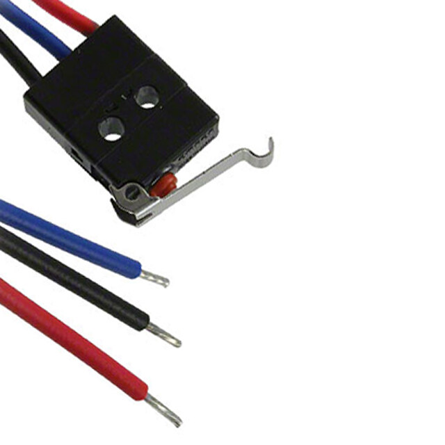
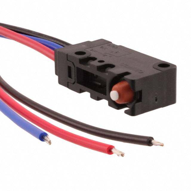
| 描述 | 基本/快动开关 ENCLOSED SW 4PDT 7A Top Plunger Wire |
| 产品分类 | |
| 产品手册 | |
| 产品图片 |
|
| rohs | 符合RoHS |
| 产品系列 | 基本/快动开关,Honeywell 404EN1-6 |
| mouser_ship_limit | 该产品可能需要其他文件才能进口到中国。 |
| 产品型号 | 404EN1-6 |
| 产品种类 | 基本/快动开关 |
| 商标 | Honeywell |
| 安装 | Panel |
| 工作力 | 0.5 N |
| 开关功能 | ON - OFF |
| 执行器 | Plunger |
| 电压额定值AC | - |
| 电压额定值DC | 28 V |
| 电流额定值 | 7 A |
| 端接类型 | Solder Pin |
| 类型 | Limit Switch |
| 触点形式 | 4PDT |
| 零件号别名 | MS21321-2 |


- 商务部:美国ITC正式对集成电路等产品启动337调查
- 曝三星4nm工艺存在良率问题 高通将骁龙8 Gen1或转产台积电
- 太阳诱电将投资9.5亿元在常州建新厂生产MLCC 预计2023年完工
- 英特尔发布欧洲新工厂建设计划 深化IDM 2.0 战略
- 台积电先进制程称霸业界 有大客户加持明年业绩稳了
- 达到5530亿美元!SIA预计今年全球半导体销售额将创下新高
- 英特尔拟将自动驾驶子公司Mobileye上市 估值或超500亿美元
- 三星加码芯片和SET,合并消费电子和移动部门,撤换高东真等 CEO
- 三星电子宣布重大人事变动 还合并消费电子和移动部门
- 海关总署:前11个月进口集成电路产品价值2.52万亿元 增长14.8%


PDF Datasheet 数据手册内容提取
MICRO SWITCH™ Environmentally Sealed Limit Switches 003125 EN Series Issue 1 Datasheet FEATURES • Circuitry options from 1PST (one-pole single throw) circuit to 6PDT (six-pole double throw) circuits for position indication of different independent circuits or providing redundant circuit capabilities • Rugged stainless steel housing and bushing • All-metal drive train for consistent operating characteristics at high or low temperatures • Most EN catalog listings are MIL-PRF-8805 compliant for stringent military and non-military applications • MIL-PRF-8805 symbol 4 (resilient) sealing to keep dust, water, and ice from entering the switch enclosure • Gold-bifurcated, gold-plated, or silver-alloy switch contacts DESCRIPTION for reliably controlling electrical loads from less than 0.5 A [low The Honeywell MICRO SWITCH™ Series of EN limit switches energy/logic level] up to 15 A (power duty) are bushing mount designed, manufactured, and qualified to • Wide temperature range from -54 °C to 125 °C [-65 °F to MIL-PRF-8805 standards. These products provide a durable 257 °F] for sea level or high altitude military or commercial switch for commercial and military aircraft as well as commercial applications and military ground-based equipment. Other applications • Assortment of switch actuators and electrical terminations include off-road equipment where severe environments are • Miniature package size [400EN Series and 600EN Series] encountered. reduces housing diameter by 30 % for smaller space required The EN Series of switches have proven to deliver consistent and on equipment reliable operation in harsh environments on critical applications for more than 65 years. POTENTIAL APPLICATIONS • Landing gear systems for commercial and military aircraft VALUE TO CUSTOMERS including helicopters • Precise and reliable position indication of critical applications - WOW switch (Weight-on-Wheels) for landing gear on aircraft and military systems - Up-lock and down-lock sensing - Landing gear bay doors closed/locked DIFFERENTIATION • External doors and hatches for commercial and military • MICRO SWITCH™ EN Series’ products are highly aircraft including helicopters configurable; offering a variety of integral actuators, electrical - Closed and locked indication for passenger entry/exit doors, circuitries, and electrical terminations cargo bay doors, and/or other doors or hatches (refueling door, APU air inlet door) • Military ground vehicles - Doors or hatches closed/locked or open • Off-road construction equipment - Doors or panels present/closed/open - Up-stop or down-stop limits PORTFOLIO Honeywell offers many Series of MICRO SWITCH™ sealed switches including the HM Series, SE Series, XE Series, HS Series, HE Series, and HR Series. Sensing and Productivity Solutions
MICRO SWITCH™ Environmentally Sealed Limit Switches, EN Series Table 1. Specifications Characteristic Parameter Description Environmentally sealed military qualified limit switch series (MIL-PRF-8805) Housing & bushing material 300 Series stainless steel Contact material Silver alloy, gold plated, gold bifurcated Mechanical endurance 25,000 cycles min. Electrical endurance 25,000 cycles min. @ rated load Circuitry 1PST (one-pole single throw) to 6PDT (six-pole double throw); reference Figure 2, page 3 Electrical rating Up to 15 A @ 28 Vdc; reference Table 2, page 2 Dielectric strength (initial) 1000 V RMS; 500 μA max. leakage Insulation resistance (initial) 500 Vdc; 1000 Megohms min. Environmental sealing Symbol 4, resilient seal per MIL-PRF-8805 Temperature range (std.) -54 °C to 85 °C [-65 °F to 185 °F] Temperature range (opt.) -54 °C to 125 °C [-65 °F to 257 °F] Shock Symbol M (100 g) per MIL-PRF-8805 Vibration Symbol 1, 10 g peak (10 Hz to 500 Hz) Standards Design conforms to MIL-PRF-8805 Table 2. Electrical Ratings Rating Sea Level @ 28 Vdc Altitude 50,000 ft Code Inrush Motor Res. Ind. Inrush Motor² Res. Ind. A 24 4 4 2 24 4 4¹ 2 B 36 6 10 3 36 6 10 3 C 30 5 15 10 30 5 15 10 D 24 4 5 3 – E – 1 0.5 – 1 0.5 F N/A 4 7 4 N/A 4 7 2.5 1 5 A for rotary switches. ² Application information only.² APPLICATION INFORMATION ONLY 2 sensing.honeywell.com
MICRO SWITCH™ Environmentally Sealed Limit Switches, EN Series STANDARD SWITCHES (see pages 4 and 5) TERMINATION While the standard EN Series provides a wide variety of products, Termination is specified in the order guides. Leadwires are Honeywell offers a miniature EN Series and a special EN Series generally six feet long, and of the gage and military specifications per the following descriptions. noted in the order guides. MINIATURE SWITCHES (see pages 6 through 8) MOUNTING Miniature type EN switches meet the demand for smaller size Plunger actuator switches mount through 5⁄8 in [Ø 0.625 in] or and lighter weight without sacrificing performance or electrical 15⁄32 in [Ø 0.469 in] holes. Lock washer, keyed washer, and wire capacity. These types are of the same construction, seal, and lock hexagon mounting nuts lock the switches in their mounting materials as the standard size EN switches. holes. Type 400EN switches are directly interchangeable with their Rotary-actuated switches mount through 15⁄32 in [Ø 0.469 in] standard size EN counterpart, yet the housings are smaller in holes. A lock washer, wire lock hexagon nut, and locating pins on diameter and lighter in weight. The miniature-size housing is 7,92 the top of the housing prevent switch rotation. mm [0.312 in] smaller in diameter, and the switch weighs 9,1 g [0.3 oz] less. Figure 1. Typical EN Switch Construction SWITCHES WITH SPECIAL REQUIREMENTS (see page 9) High velocity actuation This switch (1EN231-6) is designed to withstand near ‘‘hammer- blow’’ actuation as is found in over-center locking mechanisms. It is dimensionally interchangeable with standard listing 1EN1-6. Low force operation Special spring construction within this switch (1EN51-6) reduces the normal 6 lb to 12 lb (26,7 N to 53,4 N) EN operating force to 3 lb to 6 lb (13,3 N to 26,7 N). This switch is also dimensionally interchangeable with the standard size 1EN1-6. Increased overtravel Figure 2. Circuitry Diagrams A longer plunger and bushing on the switch (1EN61-6) extends the EN overtravel capabilities from the normal 6,35 mm to 21,8 mm [0.25 in to 0.86 in]. The longer bushing also permits additional adjustment of the plunger position or installations where an increased bushing length is required. High impact shock Catalog listing, 1EN75-R3 (M8805/65-001), has been qualified to MIL-PRF-8805, including high impact shock class H. Other switches rated for high impact shock applications incorporate the same plunger mechanism and internal switch design as used in the 1EN75-R3 and are expected to conform to the same requirements. Honeywell Sensing and Productivity Solutions 3
MICRO SWITCH™ Environmentally Sealed Limit Switches, EN Series Table 3. EN Series Order Guide - Standard Series Actuator Circuitry Termination Electrical Rating Code** Catalog Listing Military Number or Note O.F. N [lb] R.F. min. N [lb] F.P. nom. mm [in] P.T. max. mm [in] O.T. min. mm [in] D.T. max. mm [in] Bushing Thread Size Housing Height mm [in] Housing Diameter or Length mm [in] Replacement Mounting Hardware Packet Leadwire #20 26,7 to AWG (side MS24331-1 35,0 1,02 6,35 0,51 0.625-24 24,9 Ø 25,4 2PDT A [4 A] 1EN1-6 53,4 17,8 [4] 19PA8 exit) MIL- (8805/40) [1.38] [0.040] [0.250] [0.020] UNEF [0.980] [1.0] [6 to 12] DTL-22759/7 26,7 to Screw (4-48 35,0 1,02 6,35 0,51 0.625-24 38,2 Ø 25,4 19PA78- 2PDT A [4 A] 1EN1-S – 53,4 17,8 [4] thread) [1.38] [0.040] [0.250] [0.020] UNEF [1.51] [1.0] EN [6 to 12] 26,7 to Connector 35,0 1,02 6,35 0,51 0.625-24 27,9 61,0 19PA78- 2PDT A [4 A] 1EN42-R – 53,4 17,8 [4] (side exit) [1.38] [0.040] [0.250] [0.020] UNEF [1.10] [2.4] EN [6 to 12] 26,7 to Connector 35,0 1,02 6,35 0,51 0.625-24 53,3 Ø 25,4 19PA78- 2PDT A [4 A] 1EN43-R – 53,4 17,8 [4] (bottom exit) [1.38] [0.040] [0.250] [0.020] UNEF [2.1] [1.0] EN [6 to 12] R E LUNG LeAaWdwGi r(es id#e1 8 MS24331-2 26,7 to 35,0 1,27 6,35 0,89 0.625-24 38,1 Ø 38,1 P 2PDT B [10 A] 2EN1-6 53,4 22,3 [5] 19PA8 N exit) MIL- (8805/40) [1.38] [0.050] [0.250] [0.035] UNEF [1.50] [1.50] PI DTL-22759/7 [6 to 12] Leadwire #18 26,7 to 1PDT- AWG (side MS24331-3 35,0 1,52 6,35 0,89 0.625-24 33,3 Ø 38,1 C [15 A] 3EN1-6 53,4 22,3 [5] 19PA8 DB exit) MIL- (8805/40) [1.38] [0.060] [0.250] [0.035] UNEF [1.31] [1.50] [6 to 12] DTL-22759/7 Leadwire #18 26,7 to 2PDT- AWG (side MS24331-4 35,0 1,78 6,35 1,14 0.625-24 43,2 Ø 38,1 C [15 A] 4EN1-6 53,4 22,3 [5] 19PA8 DB exit) MIL- (8805/40) [1.38] [0.070] [0.250] [0.045] UNEF [1.70] [1.50] [6 to 12] DTL-22759/7 Leadwire #20 26,7 to AWG (side 35,0 1,02 6,35 0,76 0.625-24 30,5 Ø 38,1 19PA78- 4PDT A [4 A] 5EN1-6 – 53,4 17,8 [4] exit) MIL- [1.38] [0.040] [0.250] [0.030] UNEF [1.20] [1.50] EN [6 to 12] DTL-22759/7 G N Leadwire #20 L BEARILUNGER 2PDT AeWxitG) M(sIiLd-e A [4 A] 2001EN1-6 – [2656 t3,o7 ,14 t2 o ] 17,8 [4] [319.5,14 ] [01.,00420 ] [06.,23550 ] [00.,05210 ] 0.6U2N5E-F24 [02.49,890 ] Ø[ 12.50,]4 19PA8 ALP DTL-22759/7 B Leadwire #20 26,7 to AWG (side 45,2 1,02 6,35 0,51 0.625-24 24,9 Ø 25,4 19PA115- 2PDT A [4 A] 21EN9-6* FAA-PMA 53,4 17,8 [4] exit) MIL- [1.78] [0.040] [0.250] [0.020] UNEF [0.980] [1.0] EN [6 to 12] DTL-22759/7 * R Leadwire #18 26,7 to UNGE 2PDT AWG (side exit) B [10 A] 22EN9-6* – 53,4 22,3 [5] [415.7,28 ] [01.,02570 ] [06.,23550 ] [00.,08395 ] 0.6U2N5E-F24 [318.,51] Ø[ 13.85,]1 19PEAN115- L MIL-W-22759/7 [6 to 12] P R E Leadwire #18 26,7 to L 2PDT- 45,2 1,78 6,35 1,14 0.625-24 43,2 Ø 38,1 19PA115- OL AWG (side exit) C [15 A] 24EN9-6* – 53,4 22,3 [5] R DB [1.78] [0.070] [0.250] [0.045] UNEF [1.70] [1.50] EN MIL-W-22759/7 [6 to 12] Leadwire #20 26,7 to 45,2 1,02 6,35 0,76 0.625-24 30,5 Ø 38,1 19PA115- 4PDT AWG (side exit) A [4 A] 25EN9-6* FAA-PMA 53,4 17,8 [4] [1.78] [0.040] [0.250] [0.030] UNEF [1.20] [1.50] EN MIL-W-22759/7 [6 to 12] O.F.- Operating Force; R.F.- Release Force; F.P.-Free Position; P.T.-Pretravel; O.T.-Overtravel; D.T.-Differential Travel * Roller plunger field adjustable in 45° increments. ** Reference Table 2, page 2, for additional detail. 4 sensing.honeywell.com
MICRO SWITCH™ Environmentally Sealed Limit Switches, EN Series Table 3. EN Series Order Guide - Standard Series, continued Actuator Circuitry Termination Electrical Rating Code** Catalog Listing Military Number or Note O.T. Nm [in-lb] R.T. min. Nm [in-lb] P.T. degrees [nom.] T.T. degrees [nom.] D.T. max. degrees Bushing Thread Size Housing Height mm [in] Housing Diameter or Length mm [in] Replacement Mounting Hardware Packet Leadwire #20 AWG 1,36 to 31EN11-6 MS21320-1 0.469-32 54,8 Ø 25,4 2PDT (side exit) D [5 A] 2,82 [12 1,02 [9] 13° 45° 4° 19PA10 (CW) (8805/48) UNS [2.16] [1.0] MIL-W-22759/7 to 25] Leadwire #20 AWG 1,36 to 31EN1-6 MS21320-2 0.469-32 54,8 Ø 25,4 2PDT (side exit) D [5 A] 2,82 [12 1,02 [9] 13° 45° 4° 19PA10 (CCW) (8805/48) UNS [2.16] [1.0] MIL-W-22759/7 to 25] Leadwire #18 AWG 1,36 to 32EN11-6 MS21320-3 0.469-32 68,6 Ø 38,1 2PDT (side exit) B [10 A] 2,82 [12 1,02 [9] 20° 45° 6° 19PA10 (CW) (8805/48) UNS [2.70] [1.5] MIL-W-22759/7 to 25] R Leadwire #18 AWG 1,36 to EVE 2PDT (side exit) B [10 A] 32EN1-6 MS21320-4 2,82 [12 1,02 [9] 20° 45° 6° 0.469-32 68,6 Ø 38,1 19PA10 L (CCW) (8805/48) UNS [2.70] [1.5] R MIL-W-22759/7 to 25] E L ROL 2PDT- Leadwire #18 AWG 34EN11-6 MS21320-7 1,36 to 0.469-32 71,6 Ø38,1 RY DB (side exit) MIL- C [15 A] (CW) (8805/48) 2,82 [12 0,9 [8] 15° 45° 10° UNS [2.82] [1.5] 19PA10 A W-22759/7 to 25] T O R Leadwire #18 AWG 1,36 to 2PDT- 34EN1-6 MS21320-8 0.469-32 71,6 Ø 38,1 (side exit) C [15 A] 2,82 [12 0,9 [8] 15° 45° 10° 19PA10 DB (CCW) (8805/48) UNS [2.82] [1.5] MIL-W-22759/7 to 25] Leadwire #18 AWG Gold- 1,36 to 35EN27-4 0.469-32 60,7 Ø 38,1 2PDT (side exit) E [1 A] bifurcated 2,82 [12 1,02 [9] 20° 45° 6° 19PA10 (CW) UNS [2.39] [1.5] MIL-W-22759/7 contacts to 25] FAA-PMA, Leadwire #18 AWG 1,36 to 35EN24-4 Gold- 0.469-32 60,7 Ø 38,1 2PDT (side exit) E [1 A] 2,82 [12 1,02 [9] 20° 45° 6° 19PA10 (CCW) bifurcated UNS [2.39] [1.5] MIL-W-22759/7 to 25] contacts Leadwire #20 AWG Nom. 35° actuation 0.469-32 26,7 Ø 25,4 1R 2PDT (side exit) A [4 A] 41EN1-61 MS24420-1 0,34 [3] – 12° 19PA10 E in 360° rotation UNS [1.05] [1.0] V MIL-W-22759/7 E L AGE Leadwire #18 AWG Nom. 35° actuation 0.469-32 42,7 Ø 38,1 K 2PDT (side exit) B [10 A] 42EN1-61 MS24420-2 0,56 [5] – 12° 19PA10 N in 360° rotation UNS [1.68] [1.5] LI MIL-W-22759/7 Y AR Leadwire #18 AWG T 2PDT- Nom. 35° actuation 0.469-32 46,2 Ø 38,1 O (side exit) C [15 A] 44EN1-61 MS24420-4 1,13 [10] – 20° 19PA10 R DB in 360° rotation UNS [1.82] [1.5] MIL-W-22759/7 O.T.- Operating Torque; R.T.- Release Torque; P.T.-Pretravel; T.T.-Total Travel; D.T.-Differential Travel 1 These rotary linkage lever switches are continous rotation CW or CCW. ** Reference Table 2, page 2, for additional detail. Honeywell Sensing and Productivity Solutions 5
MICRO SWITCH™ Environmentally Sealed Limit Switches, EN Series Table 4. EN Series Order Guide - Miniature Series Actuator Circuitry Termination Electrical Rating Code** Catalog Listing Military Number or note O.F. N [lb] R.F. min. N [lb] F.P. nom. mm [in] P.T. max. mm [in] O.T. min. mm [in] D.T. max. mm [in] Bushing Thread Size Housing Height mm [in] Housing Diameter or Length mm [in] Replacement Mounting Hardware Packet Leadwire 26,7 to #20 AWG MS21321-1 53,4 35,0 1,02 6,35 0,51 0.625-24 24,9 Ø 17,5 2PDT (side exit) F [7 A] 402EN1-6 17,8 [4] – 8805/39 [6 to [1.38] [0.040] [0.250] [0.020] UNEF [0.98] [0.69] MIL- 12] W-22759/7 Leadwire 26,7 to #20 AWG MS21321-2 53,4 35,0 1,02 6,35 0,51 0.625-24 30,5 Ø 25,4 4PDT (side exit) F [7 A] 404EN1-6 17,8 [4] – 8805/39 [6 to [1.38] [0.040] [0.250] [0.020] UNEF [1.2] [1.0] MIL- 12] W-22759/7 Leadwire 26,7 to #20 AWG MS27240-1 53,4 22,3 1,02 3,18 0,51 0.469-32 25,4 Ø 17,5 2PDT (side exit) F [7 A] 602EN1-6 17,8 [4] 19PA9 8805/43 [6 to [0.88] [0.040] [0.125] [0.020] UNS [1.0] [0.69] MIL- 12] W-22759/7 26,7 to 22,3 1,02 3,18 0,51 0.469-32 25,4 Ø 17,5 2PDT Solder pins F [7 A] 602EN142 – 53,4 [6 17,8 [4] 19PA9 [0.88] [0.040] [0.125] [0.020] UNS [1.0] [0.69] R to 12] E G LUN Leadwire MS27240-5 26,7 to P #20 AWG N 8805/43, 53,4 22,3 1,02 3,18 0,51 0.469-32 25,4 Ø 17,5 PI 2PDT (side exit) E [1 A] 602EN222-6* Gold-plated [6 to 17,8 [4] [0.88] [0.040] [0.125] [0.020] UNS [1.0] [0.69] 19PA9 MIL- contacts 12] W-22759/7 Leadwire #20 AWG 8,9 to nom. 37,1 6,35 0,51 0.469-32 25,4 Ø 17,5 2PDT (side exit) F [7 A] 602EN602-6 FAA-PMA 17,8 4,7 [1] 0,38 19PA9 [1.46] [0.250] [0.020] UNS [1.0] [0.69] MIL- [2 to 4] [0.015] W-22759/7 Leadwire 26,7 to #20 AWG MS27240-2 53,4 22,3 1,02 3,18 0,51 0.469-32 30,5 Ø 25,4 4PDT (side exit) F [7 A] 604EN1-6 17,8 [4] 19PA9 8805/43 [6 to [0.88] [0.040] [0.125] [0.020] UNS [1.2] [1.0] MIL- 12] W-22759/7 Leadwire MS27240-6 26,7 to #20 AWG 8805/43, 53,4 22,3 1,02 3,18 0,51 0.469-32 30,5 Ø 25,4 4PDT (side exit) E [1 A] 604EN222-6* 17,8 [4] 19PA9 Gold-plated [6 to [0.88] [0.040] [0.125] [0.020] UNS [1.2] [1.0] MIL- contacts 12] W-22759/7 O.F.- Operating Force; R.F.- Release Force; F.P.-Free Position; P.T.-Pretravel; O.T.-Overtravel; D.T.-Differential Travel * Each pole (basic switch) has gold-plated silver contacts for controlling low energy loads. If the switch is applied to a power-duty application, the switch is not recommended to control a low energy load. ** Reference Table 2, page 2, for additional detail. 6 sensing.honeywell.com
MICRO SWITCH™ Environmentally Sealed Limit Switches, EN Series Table 4. EN Series Order Guide - Miniature Series, continued Actuator Circuitry Termination Electrical Rating Code** Catalog Listing Military Number or note O.F. N [lb] R.F. min. N [lb] F.P. nom. mm [in] P.T. max. mm [in] O.T. min. mm [in] D.T. max. mm [in] Bushing Thread Size Housing Height mm [in] Housing Diameter or Length mm [in] Replacement Mounting Hardware Packet Leadwire 26,7 to #20 AWG 53,4 45,2 1,02 6,35 0,51 0.625-24 24,9 Ø 17,5 19PA115- 2PDT (side exit) F [7 A] 422EN1-6* – 17,8 [4] [6 to [1.78] [0.040] [0.250] [0.020] UNEF [0.98] [0.69] EN MIL- 12] W-22759/7 Leadwire 26,7 to #20 AWG 53,4 45,2 1,02 6,35 0,51 0.625-24 30,5 Ø 25,4 4PDT (side exit) F [7 A] 424EN1-6* – 17,8 [4] 19PA8 [6 to [1.78] [0.040] [0.250] [0.020] UNEF [1.2] [1.0] MIL- 12] W-22759/7 Leadwire 26,7 to #20 AWG 6 53,4 45,2 1,02 6,35 0,76 0.625-24 32,7 Ø 38,1 (side exit) F [7 A] 426EN9-8* – 17,8 [4] 19PA8 PDT [6 to [1.78] [0.040] [0.250] [0.030] UNEF [1.29] [1.5] MIL- 12] W-22759/7 * ER Leadwire G 26,7 to N #20 AWG U MS27240-3 53,4 32,9 1,02 3,18 0,51 0.469-32 25,4 Ø 17,5 LER PL 2PDT (sidMeI Le-xit) F [7 A] 622EN1-6* 8805/43 [162 t]o 17,8 [4] [1.30] [0.040] [0.125] [0.020] UNS [1.0] [0.69] 19PA9 L W-22759/7 O R Leadwire MS27240-7 26,7 to #20 AWG 8805/43, 53,4 32,9 1,02 3,18 0,51 0.469-32 25,4 Ø 17,5 2PDT (side exit) E [1 A] 622EN222-6*1 17,8 [4] 19PA9 Gold-plated [6 to [1.30] [0.040] [0.125] [0.020] UNS [1.0] [0.69] MIL- contacts 12] W-22759/7 Leadwire 26,7 to #20 AWG MS27240-4 53,4 32,9 1,02 3,18 0,51 0.469-32 30,5 Ø 25,4 4PDT (side exit) F [7 A] 624EN1-6* 17,8 [4] 19PA9 8805/43 [6 to [1.30] [0.040] [0.125] [0.020] UNS [1.2] [1.0] MIL- 12] W-22759/7 Leadwire MS27240-8 26,7 to #20 AWG 8805/43 53,4 32,9 1,02 3,18 0,51 0.469-32 30,5 Ø 25,4 4PDT (side exit) E [1 A] 624EN222-6* 1 17,8 [4] 19PA9 Gold-plated [6 to [1.30] [0.040] [0.125] [0.020] UNS [1.2] [1.0] MIL- contacts 12] W-22759/7 O.F.- Operating Force; R.F.- Release Force; F.P.-Free Position; P.T.-Pretravel; O.T.-Overtravel; D.T.-Differential Travel 1 Each pole (basic switch) has gold-plated silver contacts for controlling low energy loads. If the switch is applied to a power-duty application, the switch is not recommended to control a low energy load. * Roller plunger field adjustable in 45° increments. ** Reference Table 2, page 2, for additional detail. Honeywell Sensing and Productivity Solutions 7
MICRO SWITCH™ Environmentally Sealed Limit Switches, EN Series Table 4. EN Series Order Guide - Miniature Series, continued Actuator Circuitry Termination Electrical Rating Code** Catalog Listing Military Number or note O.T. Nm [in-lb] R.T. min. Nm [in-lb] P.T. degrees [nom.] T.T. degrees [nom.] D.T. max. degrees Bushing Thread Size Housing Height mm [in] Housing Diameter or Length mm [in] Replacement Mounting Hardware Packet Leadwire #20 AWG Nom. 50° actuation 0.469-32 25,4 Ø 17,5 2PDT (side exit) MIL- F [7 A] 442EN1-61 – 0,34 [3] – 12° – in 360° rotation UNS [1.0] [0.69] W-22759/7 1R EVE Leadwire #20 AWG Nom. 50° actuation 0.469-32 30,23 Ø 17,5 L 4PDT (side exit) MIL- F [7 A] 444EN1-61 – 0,34 [3] – 12° – E in 360° rotation UNS [1.19] [0.69] G W-22759/7 A K LIN Leadwire #20 AWG Nom. 50° actuation 0.469-32 30,23 Ø 17,5 Y 4PDT (side exit) MIL- F [7 A] 444EN49-61 – 0,34 [3] – 12° – R in 360° rotation UNS [1.19] [0.69] TA W-22759/7 O R Leadwire #20 AWG Gold-plated Nom. 50° actuation 0.469-32 30,23 Ø 17,5 4PDT (side exit) MIL- E [1 A] 444EN222-61,2 0,34 [3] – 12° – contacts in 360° rotation UNS [1.19] [0.69] W-22759/7 O.T.- Operating Torque; R.T.- Release Torque; P.T.-Pretravel; T.T.-Total Travel; D.T.-Differential Travel 1 These rotary linkage lever switches are continous rotation CW or CCW. 2 Each pole (basic switch) has gold-plated silver contacts for controlling low energy loads. If the switch is applied to a power-duty application, the switch is not recommended to control a low energy load. ** Reference Table 2, page 2, for additional detail. 8 sensing.honeywell.com
MICRO SWITCH™ Environmentally Sealed Limit Switches, EN Series Table 5. EN Series Order Guide - Special Purpose Series Utilization Actuator Circuitry Termination Electrical Rating Code ** Catalog Listing Military Number or note O.F. N [lb] R.F. min. N [lb] F.P. nom. mm [in] P.T. max. mm [in] O.T. min. mm [in] D.T. max. mm [in] Bushing Thread Size Housing Height mm [in] Housing Diameter or Length mm [in] Replacement Mounting Hardware Packet Y H VELOCITCTUATION 2PDT MALIWLe-aGWd w(-s2iird2ee7 #5e2x90i/t7) A [4 A] 1EN231-6 – 52t36o ,,1472 [t]6o 1[74,]8 [315.3,08 ] [01.,00420 ] [05.,28340 ] [00.,05210 ] 0.6U2N5E-F24 [204.9,98 ] [215.,04] 19PEAN78- GA HI E N W FORCERATIO 2PDT MALIWLe-aGWd w(-s2iird2ee7 #5e2x90i/t7) A [4 A] 1EN51-6 – [1323 6,t3o, 7 6t o] 8[,28]9 [315.3,08 ] [01.,00420 ] [06.,23550 ] [00.,05210 ] 0.6U2N5E-F24 [204.9,98 ] [215.,04] 19PEAN78- OP LO INCREASED OVERTRAVEL N PLUNGER 2PDT MALIWLe-aGWdT yw(-sp8iierd1e eE0 #4e2x40i/t9) A [4 A] 1EN61-6 FAA-PMA 52t36o ,,1472 [t]6o 1[74,]8 [315.3,08 ] [01.,00420 ] [102.5,7000 ] [00.,05210 ] 0.6U2N5E-F24 [204.9,98 ] [215.,04] 19PEAN78- PI 7 Pin bottom 26,7 to 17,8 9,53 1,02 6,35 0,51 1.0-20 57,9 Ø 25,4 19PA121- 2PDT exit, MIL. type A [4 A] 1EN75-R – 53,4 [6 [4] [0.375] [0.040] [0.250] [0.020] UNEF [2.28] [1.0] EN connector to 12] CE 7 Pin side exit, 26,7 to N 17,8 9,53 1,02 6,35 0,51 1.0-20 36,6 26,7 19PA121- A 2PDT MIL. type con- A [4 A] 1EN76-R – 53,4 [6 T [4] [0.375] [0.040] [0.250] [0.020] UNEF [1.44] [1.05] EN SIS nector to 12] E R K 7 Pin bottom 26,7 to D SHOC 2PDT excito, nMnIeLc. ttoyrpe D [5 A] 1EN75-R3 M658-800051/ 5t3o ,142 []6 1[74,]8 [09.,35735 ] [01.,00420 ] [06.,23550 ] [00.,05210 ] 1U.0N-E2F0 [723.8,49 ] Ø[ 12.50,]4 19PEAN121- E S INCREA UNGER* 2PDT e7x ciPto,i nnMn bIeLoc.t tttooyrpme A [4 A] 21EN75-R1* – 52t36o ,,1472 [t]6o 1[74,]8 [109.7,88 ] [01.,00420 ] [06.,23550 ] [00.,05210 ] 1U.0N-E2F0 [527.2,98 ] Ø[ 12.50,]4 19PEAN121- L P R Leadwire #20 26,7 to E 17,8 19,8 1,02 6,35 0,51 1.0-20 34,5 Ø 25,4 19PA121- OLL 2PDT AWG (side exit) A [4 A] 21EN75-2* – 53,4 [6 [4] [0.78] [0.040] [0.250] [0.020] UNEF [1.36] [1.0] EN R MIL-W-22759/7 to 12] O.F.- Operating Force; R.F.- Release Force; F.P.-Free Position; P.T.-Pretravel; O.T.-Overtravel; D.T.-Differential Travel *Roller plunger field adjustable in 45° increments. ** Reference Table 2, page 2, for additional detail. Honeywell Sensing and Productivity Solutions 9
MICRO SWITCH™ Environmentally Sealed Limit Switches, EN Series OPERATION Roller Linkage Lever Actuators Plunger Actuators A threaded rod attaches to the rotary lever for positive actuation. For in-line actuation. An ice scraper ring cleans the actuator with The rotary lever operates in either direction and adjusts laterally each operation. to any position through 360°. The threaded rod pivots in two planes. The actuator has no spring return, but is controlled directly by the movement of the actuating device. Ball Bearing Plunger Actuators For random direction operation. An ice scraper ring cleans the actuator with each operation. Roller Lever Actuators For cam and slide actuation with more than a 30° rise. The actuator is available in clockwise or counterclockwise operation with a spring-return mechanism. The actuator adjusts laterally to any position through 360°. The roller is laminated phenolic. Roller Plunger Actuators For cam and slide actuation not to exceed 20° rise. Roller adjusts laterally in 45° increments. An ice scraper ring cleans the actuator with each operation. 10 sensing.honeywell.com
MICRO SWITCH™ Environmentally Sealed Limit Switches, EN Series Figure 4. Miniature-size EN Switches DIMENSIONAL DRAWINGS Figure 3. Standard-size EN Switches Figure 5. Special-purpose EN Switches NOTE: Steel plunger and actuators are made from stainless steel. Honeywell Sensing and Productivity Solutions 11
MICRO SWITCH™ Environmentally Sealed Limit Switches, EN Series Table 6. Replacement Parts Catalog Listing Description Used On 6PA30 Roller lever arm 30EN Series 6PA31 Linkage lever arm 40EN Series 6PA32 Roller lever arm 1EN and 1HE Series 6PA202-EN Roller lever arm 600EN and 600HE Series 15PA104 Roller guide and locking ring 21EN, 422/424EN Series (5⁄8 in bushing) 15PA105 Roller guide and locking ring 622/624EN Series (15⁄32 in bushing) 15PA137 Locking ring only 21EN 422/424EN Series (5⁄8 in bushing) 15PA107 Locking ring only 622EN and 624EN Series (15⁄32 in bushing) 19PA8 Military-type mounting hardware 1EN Series (5⁄8 in bushing) 19PA9 Military-type mounting hardware 600EN Series (15⁄32 in bushing) 12 sensing.honeywell.com
m WARNING ADDITIONAL MATERIALS PERSONAL INJURY The following associated literature is available on the Honeywell DO NOT USE these products as safety or emergency stop web site at sensing.honeywell.com: devices or in any other application where failure of the product • Product line guide could result in personal injury. • Product range guide Failure to comply with these instructions could result in death or serious injury. • Aerospace and defense product range guide m WARNING MISUSE OF DOCUMENTATION • The information presented in this product sheet is for reference only. Do not use this document as a product installation guide. • Complete installation, operation, and maintenance information is provided in the instructions supplied with each product. Failure to comply with these instructions could result in death or serious injury. Warranty/Remedy Honeywell warrants goods of its manufacture as being free of defective materials and faulty workmanship. Honeywell’s standard product warranty applies unless agreed to otherwise by Honeywell in writing; please refer to your order acknowledgement or consult your local sales office for specific warranty details. If warranted goods are returned to Honeywell during the period of coverage, Honeywell will repair or replace, at its option, without charge those items it finds defective. The foregoing is buyer’s sole remedy and is in lieu of all other warranties, expressed or implied, including those of merchantability and fitness for Find out more a particular purpose. In no event shall Honeywell be liable for Honeywell serves its customers consequential, special, or indirect damages. through a worldwide network While we provide application assistance personally, through our of sales offices, representatives literature and the Honeywell web site, it is up to the customer to and distributors. For application determine the suitability of the product in the application. assistance, current specifica- Specifications may change without notice. The information we tions, pricing or name of the supply is believed to be accurate and reliable as of this printing. nearest Authorized Distributor, However, we assume no responsibility for its use. contact your local sales office. To learn more about Honeywell’s sensing and control products, call +1-815-235-6847 or 1-800-537-6945, visit sensing.honeywell.com, or e-mail inquiries to info.sc@honeywell.com Sensing and Productivity Solutions Honeywell 1985 Douglas Drive North Golden Valley, MN 55422 003125-1-EN IL50 GLO October 2015 honeywell.com © 2015 Honeywell International Inc. All rights reserved.