 Datasheet下载
- 型号: D2HW-C201H
- 制造商: Omron Electronics LLC
- 库位|库存: xxxx|xxxx
- 要求:
| 数量阶梯 | 香港交货 | 国内含税 |
| +xxxx | $xxxx | ¥xxxx |
查看当月历史价格
查看今年历史价格
D2HW-C201H产品简介:
ICGOO电子元器件商城为您提供D2HW-C201H由Omron Electronics LLC设计生产,在icgoo商城现货销售,并且可以通过原厂、代理商等渠道进行代购。 D2HW-C201H价格参考¥13.51-¥16.75。Omron Electronics LLCD2HW-C201H封装/规格:快动,限位开关, Switch SPDT Chassis Mount。您可以下载D2HW-C201H参考资料、Datasheet数据手册功能说明书,资料中有D2HW-C201H 详细功能的应用电路图电压和使用方法及教程。
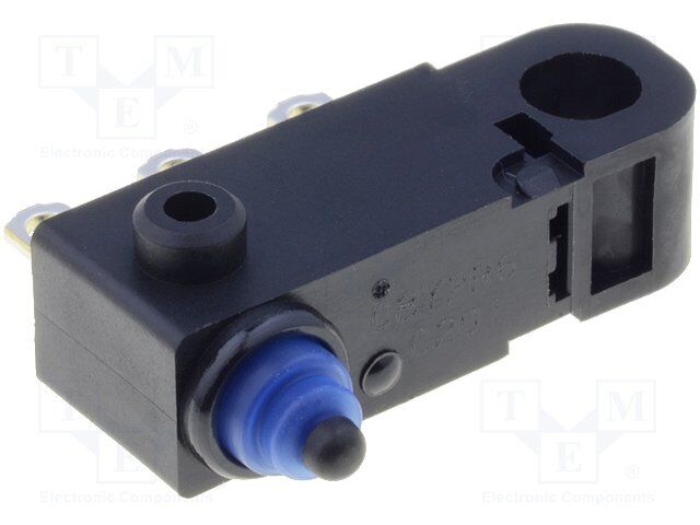
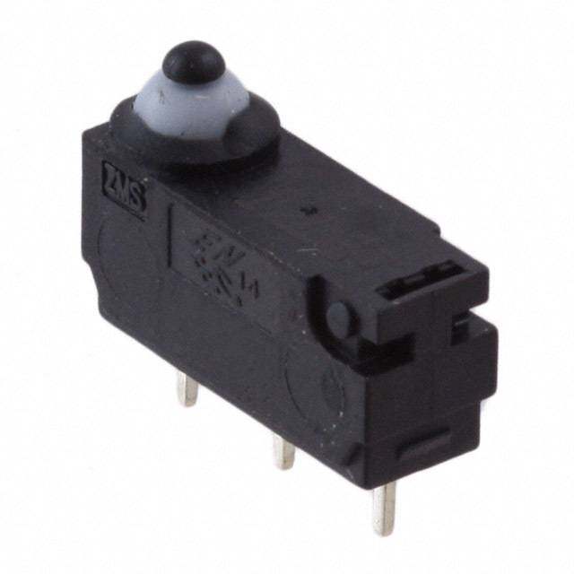
型号为D2HW-C201H、品牌为Omron Electronics Inc-EMC Div的快动限位开关,广泛应用于需要高可靠性和精确位置检测的工业自动化场景。该开关具有快速动作特性,响应灵敏,适合频繁操作的环境。典型应用包括自动化生产线中的机械定位、传送带系统的位置控制、包装机械的行程检测以及注塑机、机床等设备的安全防护与限位保护。其坚固的结构和良好的密封性能(具备一定防尘防水能力)使其可在较恶劣的工业环境中稳定运行。此外,D2HW-C201H常用于门盖联锁装置中,确保设备在门未关闭时无法启动,提升操作安全性。由于其高耐久性和长寿命,也适用于电梯、纺织机械、印刷设备等领域的位置反馈与安全控制。整体而言,该限位开关适用于对稳定性、安全性和响应速度有较高要求的工业控制系统。
| 参数 | 数值 |
| 产品目录 | |
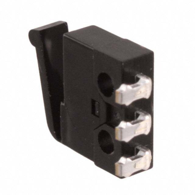
| 描述 | SWITCH SUBMINIATURE SPDT 125V基本/快动开关 Pin plunger SPDT M3 mt solder term |
| 产品分类 | |
| IP等级 | IP 67 |
| 品牌 | Omron Electronics |
| 产品手册 | |
| 产品图片 |
|
| rohs | 符合RoHS无铅 / 符合限制有害物质指令(RoHS)规范要求 |
| 产品系列 | 基本/快动开关,Omron Electronics D2HW-C201HD2HW |
| mouser_ship_limit | 该产品可能需要其他文件才能进口到中国。 |
| 数据手册 | |
| 产品型号 | D2HW-C201H |
| 产品培训模块 | http://www.digikey.cn/PTM/IndividualPTM.page?site=cn&lang=zhs&ptm=19281http://www.digikey.cn/PTM/IndividualPTM.page?site=cn&lang=zhs&ptm=25458 |
| 产品种类 | 基本/快动开关 |
| 侵入防护 | IP67 - 防尘,防水 |
| 其它名称 | D2HW-C201H-ND |
| 其它有关文件 | |
| 包装 | 散装 |
| 单位重量 | 700 mg |
| 商标 | Omron Electronics |
| 安装 | Panel |
| 安装类型 | 底座安装 |
| 工作位置 | 0.250" (6.4mm) |
| 工作力 | 0.5 N |
| 工作温度 | -40°C ~ 85°C |
| 工厂包装数量 | 250 |
| 差动行程 | 0.010" (0.25mm) |
| 开关功能 | ON - (OFF), OFF - (ON) |
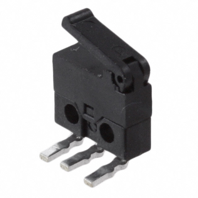
| 执行器 | Plunger, Pin |
| 操作力,扭矩 | 76gf |
| 机械寿命 | 1,000,000 次循环 |
| 标准包装 | 250 |
| 特性 | - |
| 电压额定值AC | 125 V |
| 电压额定值DC | 42 V |
| 电气寿命 | 100,000 次循环 |
| 电流额定值 | 2 A |
| 电路 | 单刀双掷 |
| 端子类型 | 焊片 |
| 端接类型 | Solder Pin |
| 类型 | Standard |
| 系列 | D2HW |
| 致动器类型 | 圆形(针状冲杆) |
| 触点形式 | SPDT |
| 超行程 | 0.055" (1.4mm) |
| 释放力 | 10gf |
| 零件号别名 | 365887 8774480 |
| 预行程 | - |
| 额定电压-AC | 125V |
| 额定电压-DC | 12V |
| 额定电流 | 100mA (AC), 2A (DC) |


- 商务部:美国ITC正式对集成电路等产品启动337调查
- 曝三星4nm工艺存在良率问题 高通将骁龙8 Gen1或转产台积电
- 太阳诱电将投资9.5亿元在常州建新厂生产MLCC 预计2023年完工
- 英特尔发布欧洲新工厂建设计划 深化IDM 2.0 战略
- 台积电先进制程称霸业界 有大客户加持明年业绩稳了
- 达到5530亿美元!SIA预计今年全球半导体销售额将创下新高
- 英特尔拟将自动驾驶子公司Mobileye上市 估值或超500亿美元
- 三星加码芯片和SET,合并消费电子和移动部门,撤换高东真等 CEO
- 三星电子宣布重大人事变动 还合并消费电子和移动部门
- 海关总署:前11个月进口集成电路产品价值2.52万亿元 增长14.8%


PDF Datasheet 数据手册内容提取
D2HW Sealed Ultra Subminiature Basic Switch Smallest sealed snap-action switch in the industry with a very long stroke for reliable ON/OFF action ●The case dimensions are 78% of conventional models, contributing to down-sizing of D mechanical modules. 2 ●Extra-long stroke even without levers. H W (OT reference value: 1.4 mm). ●Made of environmentally-friendly materials. All models are lead-free, including molded lead wire models. RoHS Compliant Model Number Legend @@@@@@@ D2HW- 1 2 3 4 5-6-7 1. Mounting Structure 4. Contact form A : Without posts (base-mounting) 1 : SPDT BR : Long post on right 2 : SPST-NC (Molded lead wire models only) BL : Long post on left 3 : SPST-NO (Molded lead wire models only) C : M3-screw mounting models 5. Terminals ER : Short post on right D, DS : PCB terminals (Straight) EL : Short post on left DR, DRS : PCB Terminals (Right-angled) 2. Raitings DL, DLS : PCB Terminals (Left-angled) 2 : 5 VDC 1mA to 12 VDC 2A H, HS : Solder terminals M, MS : Molded lead wires downwards 3. Actuator MR, MRS : Molded lead wires on right-side 0 : Pin plunger ML, MLS : Molded lead wires on left-side 1 : Hinge lever Note. UL/CSA approved versions are available. 2 : Long hinge lever In this case, a "S" will be added to the end of the model number. 3 : Simulated roller lever The Lead wire is a UL approved wire (AWG24, UL1007). 4 : Hinge roller lever 6. Special Specification 5 : Straight leaf lever 7. Special Industry Specification 6 : Leaf lever 7 : Simulated roller leaf lever 8 : Long leaf lever 1
D2HW Sealed Ultra Subminiature Basic Switch List of Models ●PCB-mounted Models List of Models Short post Long post on right on right Actuator Terminals Contact form Straight - - Pin plunger Angled D2HW-BR201DR D2HW-ER201DR Straight - - Hinge lever Angled D2HW-BR211DR D2HW-ER211DR For PCB SPDT Long hinge Straight - - D lever Angled D2HW-BR221DR D2HW-ER221DR 2 H Simulated roller Straight - - W hinge lever Angled D2HW-BR231DR D2HW-ER231DR List of Models Short post Long post on left Without posts on left Actuator Terminals Contact form Straight - - D2HW-A201D Pin plunger Angled D2HW-BL201DL D2HW-EL201DL - Straight - - D2HW-A211D Hinge lever Angled D2HW-BL211DL D2HW-EL211DL - For PCB SPDT Long hinge Straight - - D2HW-A221D lever Angled D2HW-BL221DL D2HW-EL221DL - Simulated roller Straight - - D2HW-A231D hinge lever Angled D2HW-BL231DL D2HW-EL231DL - Note1. Angled terminals and posts are the same direction. Note2. "S" is added to the end of the model number for the UL/CSA-approved version Consult your OMRON sales representative for details. 2
D2HW Sealed Ultra Subminiature Basic Switch ●Models with Solder Terminals or Molded Lead Wires List of Models Short post Long post on right on right Actuator Terminals Contact form Solder SPDT D2HW-BR201H D2HW-ER201H SPDT D2HW-BR201M D2HW-ER201M Downwards SPST-NC D2HW-BR202M D2HW-ER202M SPST-NO D2HW-BR203M D2HW-ER203M Pin plunger Molded SPST-NC D2HW-BR202MR D2HW-ER202MR lead wires Right-side SPST-NO D2HW-BR203MR D2HW-ER203MR SPST-NC D2HW-BR202ML D2HW-ER202ML Left-side SPST-NO D2HW-BR203ML D2HW-ER203ML Solder SPDT D2HW-BR211H D2HW-ER211H SPDT D2HW-BR211M D2HW-ER211M D Downwards SPST-NC D2HW-BR212M D2HW-ER212M 2 Hinge lever Molded SPST-NO D2HW-BR213M D2HW-ER213M H lead wires Right-side SPST-NC D2HW-BR212MR D2HW-ER212MR W SPST-NO D2HW-BR213MR D2HW-ER213MR SPST-NC D2HW-BR212ML D2HW-ER212ML Left-side SPST-NO D2HW-BR213ML D2HW-ER213ML Solder SPDT D2HW-BR221H D2HW-ER221H SPDT D2HW-BR221M D2HW-ER221M Downwards SPST-NC D2HW-BR222M D2HW-ER222M SPST-NO D2HW-BR223M D2HW-ER223M Long hinge lever Molded SPST-NC D2HW-BR222MR D2HW-ER222MR lead wires Right-side SPST-NO D2HW-BR223MR D2HW-ER223MR SPST-NC D2HW-BR222ML D2HW-ER222ML Left-side SPST-NO D2HW-BR223ML D2HW-ER223ML Solder SPDT D2HW-BR231H D2HW-ER231H SPDT D2HW-BR231M D2HW-ER231M Downwards SPST-NC D2HW-BR232M D2HW-ER232M Simulated roller SPST-NO D2HW-BR233M D2HW-ER233M Molded hinge lever SPST-NC D2HW-BR232MR D2HW-ER232MR lead wires Right-side SPST-NO D2HW-BR233MR D2HW-ER233MR SPST-NC D2HW-BR232ML D2HW-ER232ML Left-side SPST-NO D2HW-BR233ML D2HW-ER233ML Solder SPDT D2HW-BR241H D2HW-ER241H SPDT D2HW-BR241M D2HW-ER241M Downwards SPST-NC D2HW-BR242M D2HW-ER242M Hinge roller SPST-NO D2HW-BR243M D2HW-ER243M Molded lever SPST-NC D2HW-BR242MR D2HW-ER242MR lead wires Right-side SPST-NO D2HW-BR243MR D2HW-ER243MR SPST-NC D2HW-BR242ML D2HW-ER242ML Left-side SPST-NO D2HW-BR243ML D2HW-ER243ML Solder SPDT D2HW-BR251H D2HW-ER251H SPDT D2HW-BR251M D2HW-ER251M Downwards SPST-NC D2HW-BR252M D2HW-ER252M Straight leaf SPST-NO D2HW-BR253M D2HW-ER253M Molded lever SPST-NC D2HW-BR252MR D2HW-ER252MR lead wires Right-side SPST-NO D2HW-BR253MR D2HW-ER253MR SPST-NC D2HW-BR252ML D2HW-ER252ML Left-side SPST-NO D2HW-BR253ML D2HW-ER253ML Solder SPDT D2HW-BR261H D2HW-ER261H SPDT D2HW-BR261M D2HW-ER261M Downwards SPST-NC D2HW-BR262M D2HW-ER262M SPST-NO D2HW-BR263M D2HW-ER263M Leaf lever Molded SPST-NC D2HW-BR262MR D2HW-ER262MR lead wires Right-side SPST-NO D2HW-BR263MR D2HW-ER263MR SPST-NC D2HW-BR262ML D2HW-ER262ML Left-side SPST-NO D2HW-BR263ML D2HW-ER263ML Solder SPDT D2HW-BR271H D2HW-ER271H SPDT D2HW-BR271M D2HW-ER271M Downwards SPST-NC D2HW-BR272M D2HW-ER272M Simulated roller SPST-NO D2HW-BR273M D2HW-ER273M Molded leaf lever SPST-NC D2HW-BR272MR D2HW-ER272MR lead wires Right-side SPST-NO D2HW-BR273MR D2HW-ER273MR SPST-NC D2HW-BR272ML D2HW-ER272ML Left-side SPST-NO D2HW-BR273ML D2HW-ER273ML Solder SPDT D2HW-BR281H D2HW-ER281H SPDT D2HW-BR281M D2HW-ER281M Downwards SPST-NC D2HW-BR282M D2HW-ER282M SPST-NO D2HW-BR283M D2HW-ER283M Long leaf lever Molded SPST-NC D2HW-BR282MR D2HW-ER282MR lead wires Right-side SPST-NO D2HW-BR283MR D2HW-ER283MR SPST-NC D2HW-BR282ML D2HW-ER282ML Left-side SPST-NO D2HW-BR283ML D2HW-ER283ML Note1. The length of standard lead wires (AVSS 0.5) for molded lead wire models shown above is 30 cm. Note2. "S" is added to the end of the model number for the UL/CSA-approved version The lead wire models are UL approved wires (AWG24, UL1007). Consult your OMRON sales representative for details. 3
D2HW Sealed Ultra Subminiature Basic Switch ●Models with Solder Terminals or Molded Lead Wires List of Models Short post M3-screw Long post on left on left mounting Actuator Terminals Contact form Solder SPDT D2HW-BL201H D2HW-EL201H D2HW-C201H SPDT D2HW-BL201M D2HW-EL201M D2HW-C201M Downwards SPST-NC D2HW-BL202M D2HW-EL202M D2HW-C202M SPST-NO D2HW-BL203M D2HW-EL203M D2HW-C203M Pin plunger Molded SPST-NC D2HW-BL202MR D2HW-EL202MR D2HW-C202MR lead wires Right-side SPST-NO D2HW-BL203MR D2HW-EL203MR D2HW-C203MR SPST-NC D2HW-BL202ML D2HW-EL202ML - Left-side SPST-NO D2HW-BL203ML D2HW-EL203ML - Solder SPDT D2HW-BL211H D2HW-EL211H D2HW-C211H D SPDT D2HW-BL211M D2HW-EL211M D2HW-C211M 2 Downwards SPST-NC D2HW-BL212M D2HW-EL212M D2HW-C212M H Hinge lever Molded SPST-NO D2HW-BL213M D2HW-EL213M D2HW-C213M W lead wires Right-side SPST-NC D2HW-BL212MR D2HW-EL212MR D2HW-C212MR SPST-NO D2HW-BL213MR D2HW-EL213MR D2HW-C213MR SPST-NC D2HW-BL212ML D2HW-EL212ML - Left-side SPST-NO D2HW-BL213ML D2HW-EL213ML - Solder SPDT D2HW-BL221H D2HW-EL221H D2HW-C221H SPDT D2HW-BL221M D2HW-EL221M D2HW-C221M Downwards SPST-NC D2HW-BL222M D2HW-EL222M D2HW-C222M SPST-NO D2HW-BL223M D2HW-EL223M D2HW-C223M Long hinge lever Molded SPST-NC D2HW-BL222MR D2HW-EL222MR D2HW-C222MR lead wires Right-side SPST-NO D2HW-BL223MR D2HW-EL223MR D2HW-C223MR SPST-NC D2HW-BL222ML D2HW-EL222ML - Left-side SPST-NO D2HW-BL223ML D2HW-EL223ML - Solder SPDT D2HW-BL231H D2HW-EL231H D2HW-C231H SPDT D2HW-BL231M D2HW-EL231M D2HW-C231M Downwards SPST-NC D2HW-BL232M D2HW-EL232M D2HW-C232M Simulated roller SPST-NO D2HW-BL233M D2HW-EL233M D2HW-C233M Molded hinge lever SPST-NC D2HW-BL232MR D2HW-EL232MR D2HW-C232MR lead wires Right-side SPST-NO D2HW-BL233MR D2HW-EL233MR D2HW-C233MR SPST-NC D2HW-BL232ML D2HW-EL232ML - Left-side SPST-NO D2HW-BL233ML D2HW-EL233ML - Solder SPDT D2HW-BL241H D2HW-EL241H D2HW-C241H SPDT D2HW-BL241M D2HW-EL241M D2HW-C241M Downwards SPST-NC D2HW-BL242M D2HW-EL242M D2HW-C242M Hinge roller SPST-NO D2HW-BL243M D2HW-EL243M D2HW-C243M Molded lever SPST-NC D2HW-BL242MR D2HW-EL242MR D2HW-C242MR lead wires Right-side SPST-NO D2HW-BL243MR D2HW-EL243MR D2HW-C243MR SPST-NC D2HW-BL242ML D2HW-EL242ML - Left-side SPST-NO D2HW-BL243ML D2HW-EL243ML - Solder SPDT D2HW-BL251H D2HW-EL251H D2HW-C251H SPDT D2HW-BL251M D2HW-EL251M D2HW-C251M Downwards SPST-NC D2HW-BL252M D2HW-EL252M D2HW-C252M Straight leaf SPST-NO D2HW-BL253M D2HW-EL253M D2HW-C253M Molded lever SPST-NC D2HW-BL252MR D2HW-EL252MR D2HW-C252MR lead wires Right-side SPST-NO D2HW-BL253MR D2HW-EL253MR D2HW-C253MR SPST-NC D2HW-BL252ML D2HW-EL252ML - Left-side SPST-NO D2HW-BL253ML D2HW-EL253ML - Solder SPDT D2HW-BL261H D2HW-EL261H D2HW-C261H SPDT D2HW-BL261M D2HW-EL261M D2HW-C261M Downwards SPST-NC D2HW-BL262M D2HW-EL262M D2HW-C262M SPST-NO D2HW-BL263M D2HW-EL263M D2HW-C263M Leaf lever Molded SPST-NC D2HW-BL262MR D2HW-EL262MR D2HW-C262MR lead wires Right-side SPST-NO D2HW-BL263MR D2HW-EL263MR D2HW-C263MR SPST-NC D2HW-BL262ML D2HW-EL262ML - Left-side SPST-NO D2HW-BL263ML D2HW-EL263ML - Solder SPDT D2HW-BL271H D2HW-EL271H D2HW-C271H SPDT D2HW-BL271M D2HW-EL271M D2HW-C271M Downwards SPST-NC D2HW-BL272M D2HW-EL272M D2HW-C272M Simulated roller SPST-NO D2HW-BL273M D2HW-EL273M D2HW-C273M Molded leaf lever SPST-NC D2HW-BL272MR D2HW-EL272MR D2HW-C272MR lead wires Right-side SPST-NO D2HW-BL273MR D2HW-EL273MR D2HW-C273MR SPST-NC D2HW-BL272ML D2HW-EL272ML - Left-side SPST-NO D2HW-BL273ML D2HW-EL273ML - Solder SPDT D2HW-BL281H D2HW-EL281H D2HW-C281H SPDT D2HW-BL281M D2HW-EL281M D2HW-C281M Downwards SPST-NC D2HW-BL282M D2HW-EL282M D2HW-C282M SPST-NO D2HW-BL283M D2HW-EL283M D2HW-C283M Long leaf lever Molded SPST-NC D2HW-BL282MR D2HW-EL282MR D2HW-C282MR lead wires Right-side SPST-NO D2HW-BL283MR D2HW-EL283MR D2HW-C283MR SPST-NC D2HW-BL282ML D2HW-EL282ML - Left-side SPST-NO D2HW-BL283ML D2HW-EL283ML - Note1. The length of standard lead wires (AVSS 0.5) for molded lead wire models shown above is 30 cm. Note2. "S" is added to the end of the model number for the UL/CSA-approved version The lead wire models are UL approved wires (AWG24, UL1007). Consult your OMRON sales representative for details. 4
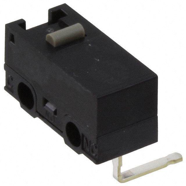
D2HW Sealed Ultra Subminiature Basic Switch Contact form ●SPDT ●SPST-NC, (Molded Lead Wire ●SPST-NO, (Molded Lead Wire Models Only) Models Only) Molded lead wire colors COM NO NC (Black) (Blue)(Red) are indicated in COM NC COM NO parentheses. (Black) (Red) (Black) (Blue) D Contact Specifications Characteristics 2 H W Specification Crossbar Permissible operating speed 1 mm to 500 mm/s (for pin plunger models) Contact Material Gold alloy Permissible operating frequency 30 operations/min Gap (standard value) 0.5 mm Insulation resistance 100 MΩ min. (at 500 VDC with insulation tester) Minimum applicable load (see note) 5 VDC 1mA Contact Terminals 100 mΩ max. resistance (initial value) Molded lead wire models 150 mΩ max. Ratings Between terminals of the 600 VAC 50/60 Hz 1min same polarity Rated voltage Resistive load Between current-carrying Dielectric 1,500 VAC 50/60 Hz 1 min 125 VAC 0.1A metal parts and ground strength 12 VDC 2A Between terminals and 24 VDC 1A non-current-carrying metal 1,500 VAC 50/60 Hz 1 min 42 VDC 0.5A parts Note.The above rating values apply under the following test conditions. Vibration Malfunction 10 to 55 Hz, 1.5 mm double amplitude (1) Ambient temperature: 20±2°C resistance * 1 (2) Ambient humidity: 65±5 % Shock Durability 1,000 m/s2 {approx. 100G} max. (3) Operating frequency: 30 operations/min resistance Malfunction * 1 300 m/s2 {approx. 30G} max. Approved Safety Standard Mechanical 1,000,000 operations min. (30 operations/min) Durability * 2 Electrical 100,000 operations min. (20 operations/min) Consult your OMRON sales representative for specific models Degree of Terminals IEC IP67 (excluding the terminals on terminal models) with standard approvals. protection molded lead wire models IEC IP67 UL (UL1054/CSA C22.2 No.55) -40 to +85°C (at ambient humidity of 60% max.) Ambient operating temperature Model D2HW (with no icing or condensation) Rated voltage Item Resistive load Ambient operating humidity 95% max. (for +5 to +35°C) 125 VAC 0.1A Weight Approx. 0.7 g (for pin plunger models with terminals) 12 VDC 2A Note.The data given above are initial values. *1. For the pin plunger models, the above values apply for use at the free 24 VDC 1A position, operating position, and total travel position. For the lever models, 42 VDC 0.5A they apply at the total travel position. Close or open circuit of the contact is 1ms max. *2. For testing conditions, consult your OMRON sales representative. 5
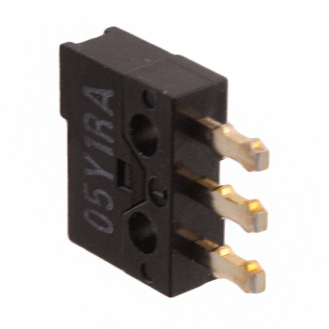
D2HW Sealed Ultra Subminiature Basic Switch Mounting Structure and Reference Positions for Operating Characteristics (Unit: mm) ●Without posts ●Long post ●M3-screw Mounting Models D2HW-A@ D2HW-B@ D2HW-C@ 4 8±0.1 2.65 1.7 dia. 1.7 dia. 13±0.1 3 -00 .1 dia. 3.3±0.15 dia. FPOPTTP 2.6±0.05 FPOPTTP FPOPTTP 3 66.5 7 Standard 6.5 Standard Position Standard Position Position 3.1+ -00..1033 D H2 13.3 5.3 Mounting Hole D1i3m.3ensions (Refe5 r -00e.2nce)5 .3 18.5 1.5 -00.15.31.5 -00.1 Mounting Hole Dimensions (Reference) W 2.4+00.1 dia. holes (Dd2eHpWth:-E@: 1.5 mm min. 3+00.1 dia. holes D2HW-B@: 5 mm min.) 2.6 (depth: 1.5 mm minM.)3 Tap 2 .4 + 00.1 13±0.1 8±0.1 ●Short post D2HW-E@ 8±0.1 1.7 dia. FPOP 2.6±0.05 TTP 3 6.5 13.3 1.5 +-00.2 5.3 Note.The reference positions used for Free Position (FP), Operating Position (OP), and Total Travel Position (TTP) values are as shown above for each type of mounting. 6
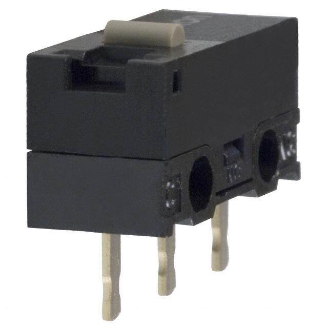
D2HW Sealed Ultra Subminiature Basic Switch Terminals/Appearances (Unit: mm) ●PCB terminals (Straight) ●PCB Terminals (Left-angled) ●PCB terminals (Right-angled) 6 6 2.5 3-0.6 0.5 3-0.6 0.5 3-0.6 0.5 5.08 5.08 5.08 5.08 (3.1) 5.08 5.08 (3.1) <PCB Mounting Dimensions (Reference)> <PCB Cutout Dimensions (Reference)> D 3-1+00.1 dia. holes 2.4+00.1 dia. holes 8±0.1 H2 (depth: 5 mm min.) 2.6 W 5.08±0.15.08±0.1 2 . 4 + 00.1 6±0.1 5.08±0.1 5.08±0.1 3-1+00.1 dia. holes ●Solder terminals 1.8 3.5 1.2 3-2 0.5 4.38 4.38 ●Molded Lead Wires on Left-side ●Molded Lead Wires on Right-side ●Molded Lead Wires Downwards COM AVSS 0.5 (Black)* NC AVSS 0.5 (Red)* Or NC AVSS 0.5 (Red) NO AVSS 0.5 (Blue) or COM AVSS 0.5 (Black) NO AVSS 0.5 (Blue) (12) (12) (12) (5) (5) 300±10 (13.3) (13.3) 300±10 * COM AVSS 0.5 (Black) * UL approved wires (AWG24, UL1007) are * UL approved wires (AWG24, UL1007) are NO AVSS 0.5 (Blue) used for UL/CSA standard approved items. used for UL/CSA standard approved items. 300±10 NC AVSS 0.5 (Red) (5) * UL approved wires (AWG24, UL1007) are used for UL/CSA standard approved items. 7
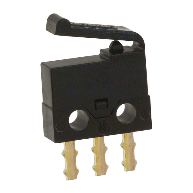
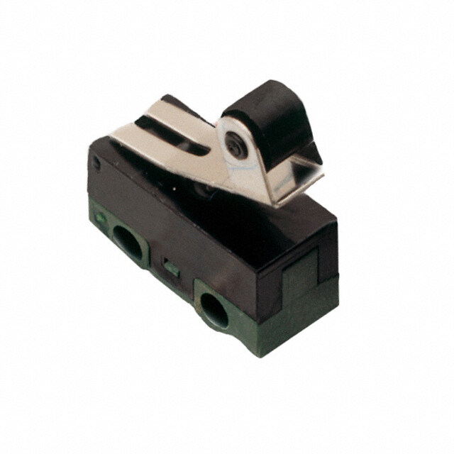
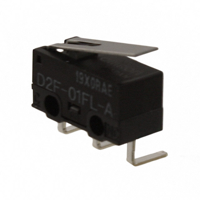
D2HW Sealed Ultra Subminiature Basic Switch Dimensions /Operating Characteristics (Unit: mm) The following illustrations and drawings are representative models. When ordering, replace @ with the code for the mounting structure, contact form and terminal that you need. See the "■List of Models" for available combinations of appearances. Refer to page 3 to 4 for the mounting structures and terminal forms. ●Pin plunger M3-screw D2HW-@20@@ 4 Without Models with Operating characteristics Type Mounting 1.7 dia. posts Posts A Models Operating Force OF Max. 0.75N {76 gf} Releasing Force RF Min. 0.10N {10 gf} D FP OP TTP Overtravel OT 1.4 mm (reference value) 2 7 Movement Differential MD Max. 0.25 mm H Free Position FP Max. 11.2 mm 7.2 mm W Operating Position OP 10.4±0.2 mm 6.4±0.2 mm 5.3 Total Travel Position TTP Max. 9.1 mm 5.1 mm ●Hinge Lever M3-screw D2HW-@21@@ Without Models A t0.3 3.4 Operating characteristics Type posts with Posts Mounting 13 Stainless-steel lever Models (1.15) Operating Force OF Max. 0.75N {76 gf} Releasing Force RF Min. 0.07N {7 gf} FP OP TTP (0.4) Overtravel OT 1.6 mm (reference value) 7 Movement Differential MD Max. 0.5 mm Free Position FP Max. 12.8 mm 8.8 mm Operating Position OP 11.5±0.5 mm 7.5±0.5 mm Total Travel Position TTP Max. 10 mm 6 mm ●Long Hinge Lever D2HW-@22@@ Operating Without Models M3-screw A 3.4 characteristics Type posts with Posts Mounting Models 20 t0.3 Stainless-steel lever Operating Force OF Max. 0.5N {50 gf} Releasing Force RF Min. 0.03N {3 gf} (1.15) FP OP Overtravel OT 2.5 mm (reference value) TTP Movement Differential MD Max. 0.8 mm (0.4) 7 Free Position FP Max. 15.5 mm 11.5 mm Operating Position OP 13.3±0.8 mm 9.3±0.8 mm Total Travel Position TTP Max. 11 mm 7 mm ●Simulated Roller Lever D2HW-@23@@ Operating Without Models M3-screw A R2 3.4 characteristics Type posts with Posts Mounting Models 15 t0.3 Stainless-steel lever Operating Force OF Max. 0.65N {66 gf} Releasing Force RF Min. 0.05N {5 gf} (1.15) Overtravel OT 1.9 mm (reference value) FP OP Movement Differential MD Max. 0.5 mm TTP (0.4) Free Position FP Max. 16.5 mm 12.5 mm 7 Operating Position OP 15.2±0.5 mm 11.2±0.5 mm Total Travel Position TTP Max. 13.5 mm 9.5 mm ●Hinge Roller Lever D2HW-@24@@ M3-screw 4.8×2.8 dia. Operating Type Models with Mounting Polyacetal resin rollerA 8±0.1 (4.6) characteristics Posts Models 15 Operating Force OF Max. 0.65N {66 gf} t0.3 Releasing Force RF Min. 0.03N {3 gf} Stainless-steel lever Overtravel OT 1.9 mm (reference value) FP OPTTP (1.15) Movement Differential MD Max. 0.6 mm Free Position FP Max. 15.3 mm 3 Operating Position OP 14±0.6 mm (0.4) 6.5 Total Travel Position TTP Max. 12.3 mm Note1. Unless otherwise specified, a tolerance of ±0.2mm applies to all dimensions. Note2. The operating characteristics are for operation in the A direction ( ). 8
D2HW Sealed Ultra Subminiature Basic Switch ●Leaf straight lever D2HW-@25@@ M3-screw 8±0.1 Operating Type Models with Mounting 1.7 dia. characteristics Posts Models Operating Force OF Max. 1.2N {122 gf} FPOP 2.6±0.05 Releasing Force RF Min. 0.05N {5 gf} TTP 3 Overtravel OT 2.5 mm (reference value) 6.5 Movement Differential MD Max. 0.7 mm Free Position FP Max. 11.9 mm Operating Position OP 8.1±0.8 mm 13.3 1.5 +-00.2 5.3 Total Travel Position TTP Max. 6.0 mm D 2 H ●Leaf Lever W D2HW-@26@@ 2.65 M3-screw 8±0.1 Operating Type Models with Mounting A t0.3 Stainless-steel lever 3.4 characteristics Posts Models 14 (1.7) Operating Force OF Max. 1.8N {183 gf} Releasing Force RF Min. 0.20N {20 gf} FP OPTTP Overtravel OT 1.8 mm (reference value) 3 Movement Differential MD Max. 0.5 mm 6.5 Free Position FP Max. 9.3 mm Operating Position OP 7.4±0.5 mm Total Travel Position TTP Max. 5.8 mm ●Simulated Roller Lever D2HW-@27@@ M3-screw A 2.R625 16 t0.3 Stainless-steel lever 3.4 Ochpaerraacttinegri stics Type MoPdeolsst sw ith MMooudnetilnsg 8±0.1 Operating Force OF Max. 1.8N {183 gf} (1.7) FP OP Releasing Force RF Min. 0.20N {20 gf} TTP Overtravel OT 2.0 mm (reference value) 3 Movement Differential MD Max. 0.5 mm 6.5 Free Position FP Max. 13.0 mm Operating Position OP 10.8±0.5 mm Total Travel Position TTP Max. 8.9 mm ●Long Leaf Lever D2HW-@28@@ A 20.85±1 t0.2 Stainless-steel lever M3-screw Operating Models with Type Mounting 18.5 characteristics Posts 2.65 13±0.1 Models FP OP Operating Force OF Max. 0.9N {92 gf} TTP Releasing Force RF Min. 0.05N {5 gf} 3.3±0.15 dia. Overtravel OT 2.8 mm (reference value) 3 3.1+-00..0133 6 Movement Differential MD Max. 0.7 mm Free Position FP Max. 19 mm (12) 3 -00. 1 dia. Operating Position OP 15.4±1.5 mm Total Travel Position TTP Max. 12.8 mm * COM AVSS 0.5 (Black) NO AVSS 0.5 (Blue) NC AVSS 0.5 (Red) 300±10 (5) (13.3) 1.5 -00.1 5.3 1.5 -00.1 * UL approved wires (AWG24, UL1007) are used for UL/CSA standard approved items. Note1. Unless otherwise specified, a tolerance of ±0.2mm applies to all dimensions. Note2. The operating characteristics are for operation in the A direction ( ). 9
D2HW Sealed Ultra Subminiature Basic Switch Precautions ★Please refer to "General Information" for correct use. Cautions Correct Use ●Degree of Protection ●Mounting •Do not use this product underwater. •Turn OFF the power supply before mounting or removing the Although molded lead wire models satisfy the test conditions Switch, wiring, or performing maintenance or inspection. for the standard given below, this test is to check the ingress of Failure to do so may result in electric shock or burning. water into the switch enclosure after submerging the Switch in •For M3-screw mounting models, use M3 mounting screws with D water for a given time. Satisfying this test condition does not plane washers or spring washers to securely mount the 2 mean that the Switch can be used underwater. Switch. H W JIS C0920: Tighten the screws to a torque of 0.27 to 0.29 N·m {27.5 to Degrees of protection provided by enclosures of electrical 29.5 gf}. Exceeding the specified torque may result in apparatus (IP Code) deterioration of the sealing or damage. IEC 60529: •For models with posts, secure the posts by thermal caulking or Degrees of protection provided by enclosures (IP Code) by pressing into an attached device. When pressed into an Degree of protection: IP67 attached device, provide guides on the opposite ends of the (check water intrusion after immersion posts to ensure that they do not fall out or rattle. for 30 min. submerged 1m underwater) Thermal caulking conditions varies according to the equipment, •Do not operate the Switch when it is exposed to water spray, jig and base used for switch mounting. Consult your OMRON or when water drops adhere to the Switch surface, or during sales representative for details. sudden temperature changes, otherwise water may intrude ●Operating Body into the interior of the Switch due to a suction effect. •Prevent the Switch from coming into contact with oil and •Use an operating body with low frictional resistance and of a chemicals. shape that will not interfere with the sealing rubber, otherwise Otherwise, damage to or deterioration of Switch materials may the plunger may be damaged or the sealing may deteriorate. result. ●Handling •Do not use the Switch in areas where it is exposed to silicon •Do not handle the Switch in a way that may cause damage to adhesives, oil, or grease. Otherwise faulty contact may result the sealing rubber. due to the generation of silicon oxide. •When handling the Switch, ensure that pressure is not applied ●Soldering to the posts in the directions shown in the following diagram. Also, ensure that uneven pressure or pressure in a direction When soldering the lead wire to the terminal, first insert the other than the operating direction is not applied to the Actuator lead wire conductor through the terminal hole and then as shown in the following diagram. Otherwise, the post, conduct soldering. Actuator, or Switch may be damaged, or the service life may Make sure that the temperature of the soldering iron tip does be reduced. not exceed 300°C, and complete the soldering within 3 seconds. Do not apply any external force for 1 minute after soldering. Soldering at an excessively high temperature or soldering for more than 3 seconds may deteriorate the characteristics of the Switch. In case of automatic soldering, please do not apply the heat beyond 260°C within 5 seconds. Pay careful attention so that flux or solder liquid does not flow over the edge of the PCB panel. ●Wiring Molded Lead Wire Models •When wiring molded lead wire models, ensure that there is no ●Side-actuated (Cam/Dog) Operation weight applied on the wire or that there are no sharp bends •When using a cam or dog to operate the Switch, factors such near the parts where the wire is drawn out. as the operating speed, operating frequency, push-button Otherwise, damage to the Switch or deterioration in the indentation, and material and shape of the cam or dog will sealing may result. affect the durability of the Switch. Confirm performance specifications under actual operating conditions before using ●Using Micro Loads the Switch in applications. •Even when using micro load models within the operating range shown below, if inrush/surge current occurs, it may increase the contact wear and so decrease durability. Therefore, insert a contact protection circuit where necessary. 10
D2HW Sealed Ultra Subminiature Basic Switch D 2 H W (cid:129) Application examples provided in this document are for reference only. In actual applications, confirm equipment functions and safety before using the product. (cid:129) Consult your OMRON representative before using the product under conditions which are not described in the manual or applying the product to nuclear control systems, railroad systems, aviation systems, vehicles, combustion systems, medical equipment, amusement machines, safety equipment, and other systems or equipment that may have a serious influence on lives and property if used improperly. Make sure that the ratings and performance characteristics of the product provide a margin of safety for the system or equipment, and be sure to provide the system or equipment with double safety mechanisms. Note: Do not use this document to operate the Unit. OMRON Corporation Electronic and Mechanical Components Company Contact: www.omron.com/ecb Cat. No. B105-E1-08 0517(0207)(O) 11
Mouser Electronics Authorized Distributor Click to View Pricing, Inventory, Delivery & Lifecycle Information: O mron: D2HW-BL201M D2HW-BR201DR D2HW-BL231M D2HW-BL261M D2HW-C213MR D2HW-BR211M D2HW- BL211M D2HW-BL281M D2HW-BL213MR D2HW-BL213ML D2HW-BR261M D2HW-BR221M D2HW-BR212ML D2HW-BR212MR D2HW-BR211DR D2HW-BL271M D2HW-BR213MR D2HW-BR213ML D2HW-BL201DL D2HW- BR281M D2HW-BR201M D2HW-BL221M D2HW-C212MR D2HW-A201D D2HW-BR271M D2HW-BR231H D2HW- BR231M D2HW-C211M D2HW-C201M D2HW-C201H D2HW-BL212MR D2HW-BL212ML D2HW-BL221DL D2HW- C203MRS D2HW-BR221DR D2HW-BR231DR D2HW-BL211DL D2HW-BL231DL D2HW-A211D D2HW-A221D D2HW-A231D D2HW-BR201H D2HW-BR202M D2HW-BR203M D2HW-BL201H D2HW-BL202M D2HW-BL203M D2HW-C202M D2HW-C203M D2HW-BR202MR D2HW-BR203MR D2HW-BR202ML D2HW-BR203ML D2HW- BR211H D2HW-BR212M D2HW-BR213M D2HW-BR221H D2HW-BR222M D2HW-BR223M D2HW-BR222MR D2HW-BR223MR D2HW-BR222ML D2HW-BR223ML D2HW-BR232M D2HW-BR233M D2HW-BR232MR D2HW- BR233MR D2HW-BR232ML D2HW-BR233ML D2HW-BR261H D2HW-BR262M D2HW-BR263M D2HW-BR262MR D2HW-BR263MR D2HW-BR262ML D2HW-BR263ML D2HW-BR271H D2HW-BR272M D2HW-BR273M D2HW- BR272MR D2HW-BR273MR D2HW-BR272ML D2HW-BR273ML D2HW-BL202MR D2HW-BL202ML D2HW- BL203ML D2HW-BL211H D2HW-BL212M D2HW-BL213M D2HW-BL221H D2HW-BL222M D2HW-BL223M D2HW-BL222MR D2HW-BL223MR D2HW-BL222ML D2HW-BL223ML D2HW-BL231H D2HW-BL232M D2HW- BL233M D2HW-BL232MR