ICGOO在线商城 > 32305

 Datasheet下载
- 型号: 32305
- 制造商: Parallax
- 库位|库存: xxxx|xxxx
- 要求:
| 数量阶梯 | 香港交货 | 国内含税 |
| +xxxx | $xxxx | ¥xxxx |
查看当月历史价格
查看今年历史价格
32305产品简介:
ICGOO电子元器件商城为您提供32305由Parallax设计生产,在icgoo商城现货销售,并且可以通过原厂、代理商等渠道进行代购。 提供32305价格参考¥34.12-¥34.12以及Parallax32305封装/规格参数等产品信息。 你可以下载32305参考资料、Datasheet数据手册功能说明书, 资料中有32305详细功能的应用电路图电压和使用方法及教程。
| 参数 | 数值 |
| 产品目录 | 编程器,开发系统嵌入式解决方案 |
| 描述 | KIT EDUCATION PROPELLER开发板和工具包 - 其他处理器 Propeller Education Kit |
| 产品分类 | 评估板 - 嵌入式 - MCU, DSP工程工具 |
| 品牌 | Parallax Inc |
| 产品手册 | |
| 产品图片 |
|
| rohs | 符合RoHS含铅 / 不符合限制有害物质指令(RoHS)规范要求 |
| 产品系列 | 嵌入式开发工具,嵌入式处理器开发套件,开发板和工具包 - 其他处理器,Parallax 32305Propeller™ |
| 数据手册 | |
| 产品型号 | 32305 |
| 产品 | Development Kits |
| 产品目录页面 | |
| 产品种类 | 开发板和工具包 - 其他处理器 |
| 内容 | 板,电缆,配件 |
| 单位重量 | 688.281 g |
| 商标 | Parallax |
| 安装类型 | 插口 |
| 工作电源电压 | 9 V |
| 工具用于评估 | P8X32A-D40 |
| 平台 | 培训套件 |
| 接口类型 | USB |
| 描述/功能 | Propeller Education Kit - 40-Pin DIP Version |
| 操作系统 | - |
| 板类型 | 评估平台 |
| 标准包装 | 1 |
| 核心 | COGs |
| 核心处理器 | - |
| 相关产品 | /product-detail/zh/P8X32A-D40/P8X32A-D40-ND/1136005/product-detail/zh/P8X32A-M44/P8X32A-M44-ND/1136006/product-detail/zh/P8X32A-Q44/P8X32A-Q44-ND/1136007 |
| 类型 | MCU 32-位 |
| 配套使用产品/相关产品 | P8X32A |
| 配用 | /product-detail/zh/122-32000/122-32000-ND/1774505/product-detail/zh/130-32305/130-32305-ND/1774526/product-detail/zh/130-32000/130-32000-ND/1774527 |


- 商务部:美国ITC正式对集成电路等产品启动337调查
- 曝三星4nm工艺存在良率问题 高通将骁龙8 Gen1或转产台积电
- 太阳诱电将投资9.5亿元在常州建新厂生产MLCC 预计2023年完工
- 英特尔发布欧洲新工厂建设计划 深化IDM 2.0 战略
- 台积电先进制程称霸业界 有大客户加持明年业绩稳了
- 达到5530亿美元!SIA预计今年全球半导体销售额将创下新高
- 英特尔拟将自动驾驶子公司Mobileye上市 估值或超500亿美元
- 三星加码芯片和SET,合并消费电子和移动部门,撤换高东真等 CEO
- 三星电子宣布重大人事变动 还合并消费电子和移动部门
- 海关总署:前11个月进口集成电路产品价值2.52万亿元 增长14.8%


PDF Datasheet 数据手册内容提取
Propeller Education Kit Labs Fundamentals Version 1.2 (web release 2) By Andy Lindsay
WARRANTY Parallax Inc. warrants its products against defects in materials and workmanship for a period of 90 days from receipt of product. If you discover a defect, Parallax Inc. will, at its option, repair or replace the merchandise, or refund the purchase price. Before returning the product to Parallax, call for a Return Merchandise Authorization (RMA) number. Write the RMA number on the outside of the box used to return the merchandise to Parallax. Please enclose the following along with the returned merchandise: your name, telephone number, shipping address, and a description of the problem. Parallax will return your product or its replacement using the same shipping method used to ship the product to Parallax. 14-DAY MONEY BACK GUARANTEE If, within 14 days of having received your product, you find that it does not suit your needs, you may return it for a full refund. Parallax Inc. will refund the purchase price of the product, excluding shipping/handling costs. This guarantee is void if the product has been altered or damaged. See the Warranty section above for instructions on returning a product to Parallax. COPYRIGHTS AND TRADEMARKS This documentation is copyright © 2006-2010 by Parallax Inc. By downloading or obtaining a printed copy of this documentation or software you agree that it is to be used exclusively with Parallax products. Any other uses are not permitted and may represent a violation of Parallax copyrights, legally punishable according to Federal copyright or intellectual property laws. Any duplication of this documentation for commercial uses is expressly prohibited by Parallax Inc. Duplication for educational use is permitted, subject to the following Conditions of Duplication: Parallax Inc. grants the user a conditional right to download, duplicate, and distribute this text without Parallax's permission. This right is based on the following conditions: the text, or any portion thereof, may not be duplicated for commercial use; it may be duplicated only for educational purposes when used solely in conjunction with Parallax products, and the user may recover from the student only the cost of duplication. This text is available in printed format from Parallax Inc. Because we print the text in volume, the consumer price is often less than typical retail duplication charges. Propeller, Penguin, and Spin are trademarks of Parallax Inc. BASIC Stamp, Stamps in Class, Boe-Bot, SumoBot, Scribbler, Toddler, and SX-Key are registered trademarks of Parallax, Inc. If you decide to use any trademarks of Parallax Inc. on your web page or in printed material, you must state that (trademark) is a (registered) trademark of Parallax Inc.” upon the first appearance of the trademark name in each printed document or web page. Other brand and product names herein are trademarks or registered trademarks of their respective holders. ISBN 9781928982555 1.2.0-10.07.12-HKTP — (WEB RELEASE 2) DISCLAIMER OF LIABILITY Parallax Inc. is not responsible for special, incidental, or consequential damages resulting from any breach of warranty, or under any legal theory, including lost profits, downtime, goodwill, damage to or replacement of equipment or property, or any costs of recovering, reprogramming, or reproducing any data stored in or used with Parallax products. Parallax Inc. is also not responsible for any personal damage, including that to life and health, resulting from use of any of our products. You take full responsibility for your Propeller microcontroller application, no matter how life-threatening it may be. INTERNET DISCUSSION LISTS We maintain active web-based discussion forums for people interested in Parallax products. These lists are accessible from www.parallax.com via the Support → Discussion Forums menu. These are the forums that we operate from our web site: Propeller Chip – This list is specifically for our customers using Propeller chips and products. BASIC Stamp – This list is widely utilized by engineers, hobbyists and students who share their BASIC Stamp projects and ask questions. Stamps in Class® – Created for educators and students, subscribers discuss the use of the Stamps in Class series of tutorials in their courses. The list provides an opportunity for both students and educators to ask questions and get answers. Parallax Educators – A private forum exclusively for educators and those who contribute to the development of Stamps in Class and Propeller Education materials. Parallax created this group to obtain feedback on our educational materials and to provide a place for educators to develop and share classroom resources. Robotics – Designed for Parallax robots, this forum is intended to be an open dialogue for robotics enthusiasts using the Boe-Bot®, SumoBot®, Scribbler® or their own custom robots built with Parallax microcontrollers and sensors.. Sensors – A place to discuss interfacing Parallax sensors to microcontrollers. PropScope – Discussion and technical assistance for using this PC-based digital storage oscilloscope and logic analyzer, designed with a Propeller P8X32A on board. HYDRA Game Development – For creating and sharing games on this Propeller P8X32A-based system. ERRATA While great effort is made to assure the accuracy of our texts, errors may still exist. If you find an error, please let us know by sending an email to editor@parallax.com. We continually strive to improve all of our educational materials and documentation, and frequently revise our texts. Occasionally, an errata sheet with a list of known errors and corrections for a given text will be posted to our web site, www.parallax.com. Please check the individual product page’s free downloads for an errata file.
Table of Contents Table of Contents PREFACE...............................................................................................................................................5 1: PROPELLER MICROCONTROLLER & LABS OVERVIEW..............................................................7 The Propeller Microcontroller.............................................................................................................7 The Propeller Education Kit Hardware.............................................................................................12 The Propeller Education Kit Labs.....................................................................................................14 2: SOFTWARE, DOCUMENTATION & RESOURCES........................................................................17 Download Software and Documentation..........................................................................................17 Useful Web Sites..............................................................................................................................18 Tech Support Resources.................................................................................................................18 3: SETUP AND TESTING LAB FOR 40-PIN DIP PE PLATFORM......................................................19 The PE Platform...............................................................................................................................19 Procedure Overview.........................................................................................................................23 Inventory Equipment and Parts........................................................................................................24 Assemble the Breadboards..............................................................................................................25 Set up PE Platform Wiring and Voltage Regulators.........................................................................27 Test the PE Platform Wiring.............................................................................................................29 Socket the Propeller Chip and EEPROM.........................................................................................30 Load a Test Program and Test the I/O Pins....................................................................................32 Before Changing or Adjusting Circuits.............................................................................................37 Propeller Supply Voltage Regulation – It’s Important!.....................................................................37 Troubleshooting for the 40-Pin DIP PE Platform Setup...................................................................39 4: I/O AND TIMING BASICS LAB.........................................................................................................45 Introduction.......................................................................................................................................45 Propeller Nomenclature....................................................................................................................46 Lights on with Direction and Output Register Bits............................................................................47 I/O Pin Group Operations.................................................................................................................49 Reading an Input, Controlling an Output..........................................................................................50 Timing Delays with the System Clock..............................................................................................51 System Clock Configuration and Event Timing................................................................................53 More Output Register Operations....................................................................................................55 Conditional Repeat Commands.......................................................................................................57 Operations in Conditions and Pre and Post Operator Positions......................................................58 Some Operator Vocabulary..............................................................................................................60 Shifting LED Display.........................................................................................................................61 Variable Example.............................................................................................................................62 Timekeeping Applications................................................................................................................64 Study Time.......................................................................................................................................66 5: METHODS AND COGS LAB............................................................................................................69 Introduction.......................................................................................................................................69 Defining a Method’s Behavior with Local Variables.........................................................................70 Calling a Method..............................................................................................................................70 Launching Methods into Cogs..........................................................................................................73 How Much Stack Space for a Method Launched into a Cog?.........................................................75 Method Calls and the Result Variable..............................................................................................77 Cog ID Indexing................................................................................................................................78 Study Time.......................................................................................................................................80 Propeller Education Kit Labs: Fundamentals · Page 3
Table of Contents 6: OBJECTS LAB.................................................................................................................................83 Introduction......................................................................................................................................83 Method Call Review.........................................................................................................................85 Calling Methods in Other Objects with Dot Notation.......................................................................85 Objects that Launch Processes into Cogs.......................................................................................88 Conventions for Start and Stop Methods in Library Objects...........................................................92 Documentation Comments..............................................................................................................92 Public vs. Private methods..............................................................................................................95 Multiple Object Instances.................................................................................................................96 Propeller Chip – PC Terminal Communication................................................................................97 Parallax Serial Terminal.spin and Other Library Objects..............................................................102 Sending Values from Parallax Serial Terminal to the Propeller Chip............................................106 Terminal I/O Pin Input State Display.............................................................................................109 Terminal LED Output Control........................................................................................................111 The DAT Block and Address Passing...........................................................................................112 The Float and FloatString Objects.................................................................................................114 Objects that Use Variable Addresses............................................................................................115 Passing Starting Addresses to Objects that Work with Variable Lists...........................................117 Study Time.....................................................................................................................................120 7: COUNTER MODULES AND CIRCUIT APPLICATIONS LAB.......................................................125 Introduction....................................................................................................................................125 How Counter Modules Work..........................................................................................................126 Measuring RC Decay with a Positive Detector Mode....................................................................126 D/A Conversion – Controlling LED Brightness with DUTY Modes................................................135 Special Purpose Registers............................................................................................................140 Generating Piezospeaker Tones with NCO Mode.........................................................................143 Applications - IR Object and Distance Detection with NCO and DUTY Modes............................153 Counting Transitions with POSEDGE and NEGEDGE Modes.....................................................158 PWM with the NCO Modes............................................................................................................162 Probe and Display PWM – Add an Object, Cog and Pair of Counters..........................................165 PLL Modes for High-Frequency Applications................................................................................171 Metal Detection with an LC Circuit Using PLL and POS Detector Modes.....................................176 Study Time.....................................................................................................................................185 APPENDIX A: OBJECT CODE LISTINGS........................................................................................191 Parallax Serial Terminal.spin.........................................................................................................191 SquareWave.spin..........................................................................................................................200 APPENDIX B: STUDY SOLUTIONS.................................................................................................201 I/O and Timing Basics Lab Study Solutions..................................................................................201 Methods and Cogs Lab Study Solutions.......................................................................................207 Objects Lab Study Solutions..........................................................................................................209 Counter Modules and Circuit Applications Lab Study Solutions...................................................214 APPENDIX C: PE KIT COMPONENTS LISTING..............................................................................224 APPENDIX D: PROPELLER P8X32A BLOCK DIAGRAM................................................................226 APPENDIX E: LM2940CT-5.0 CURRENT LIMIT CALCULATIONS..................................................227 INDEX................................................................................................................................................229 Page 4 · Propeller Education Kit Labs: Fundamentals
Preface Preface Since the Propeller chip comes in a 40-Pin DIP package, a pluggable breadboard kit for the Propeller chip made a lot of sense. The support circuits for the Propeller chip, including EEPROM program memory, voltage regulators, crystal oscillator, and Propeller Plug programming tool are all also available in versions that can be plugged into a breadboard, so why not? It also makes a great deal of sense from the college and university lab standpoint. Provide a simple kit that students can afford, that is reusable, with a microcontroller that excels in a multitude of electronics, robotics, and embedded systems projects. With that in mind, the PE DIP Plus Kit was put together, as a bag that includes the Propeller microcontroller, “plus” all the other parts you might need to make it work. The PE DIP Plus Kit made sense for folks who have already have breadboards and some experience, but what about a student who maybe just completed the Stamps in Class What’s a Microcontroller tutorial, and is interested in approaching the Propeller chip as a kit and tutorial as well? With this student in mind, another bag of parts was assembled, along with a series of activities that put the parts in the bag to work with the Propeller microcontroller. The bag of parts ended up with the name PE Project Parts, and the activities became the PE Kit Labs. The PE Kit Labs in this text are written primarily for college and university students with some previous programming and electronics experience, preferably with microcontrollers. Subjects introduced include: Microcontroller basics such as I/O control and timing with the system clock Programming topics such as operators, method calls, and objects, and variable addresses Programmed multiprocessor control Microcontroller-circuit interactions with indicator lights, pushbuttons, circuits that sense the environment and can be measured with RC decay, frequency circuits (speakers), and frequency selective circuits Advanced topics include utilizing counter modules to perform tasks in the background This collection of PE Kit Labs is intended give the reader a good start with programming the Propeller chip and using it in projects. However, this book is just a start. Introducing all aspects of the Propeller microcontroller with PE Kit Labs would take several such books, so additional labs are available online. More labs and applications will be posted periodically. This text also includes pointers to the wealth of information available for the Propeller chip in the Propeller Manual, Propeller Datasheet, Propeller Forum, and Propeller Object Exchange, as well as examples of using these resources. The reader is especially encouraged to utilize the Propeller Manual as a reference while going through these labs. The Propeller Manual’s contents and index will provide references to more information about any topic introduced in these labs. The Propeller Chip Forum at forums.parallax.com has a Propeller Education Kit Labs sticky-thread with links to discussions about each lab. The reader is encouraged to utilize this resource for posting questions about topics in the PE Kit Labs as well as comments and suggestions. Parallax collects this feedback and incorporates it into future revisions of each lab. Also, if you (or your students) prototyped something cool with the PE Kit, by all means, post your documented project to the forums so that others can see what you did and how you did it. Propeller Education Kit Labs: Fundamentals · Page 5
Preface About Version 1.2 This revision replaces the cadmium sulfide based photoresistor with a cadmium-free phototransistor that meets the European Union’s Restriction of Hazardous Substances guidelines. The Setup and Testing instructions include additions for enhanced Propeller supply voltage stability. In addition, the Parallax Serial Terminal object replaces the FullDuplexSerial Plus object. Acknowledgements Parallaxians: Author: Andy Lindsay, Applications Engineer Cover art: Jennifer Jacobs, Art Director Editing: Stephanie Lindsay, Technical Editor Illustrations: Andy Lindsay, with help from Rich Allred, Manufacturing Lead Photography: Rich Allred Review: Jessica Uelmen, Education Associate Parallax Community – thanks to: Aaron Klapheck for commented code illustrating cog variable bookkeeping in the Advanced Topic: Inside Start and Stop methods section of the Objects Lab. Engineering students at University of California Davis and California State University Sacramento who used the PE Kit in their projects and submitted great questions and bug reports. Steve Nicholson for his incisive and thorough review of earlier drafts of the PE Kit Labs. Page 6 · Propeller Education Kit Labs: Fundamentals
1: Propeller Microcontroller & Labs Overview 1: Propeller Microcontroller & Labs Overview This chapter provides an abbreviated overview of the Propeller Microcontroller and some introductory information about the Propeller Education Kit and Labs. More detailed information about the Propeller microcontroller, its architecture, and programming languages can be found in the Propeller Manual and Propeller Datasheet. Both are available from the Downloads link at www.parallax.com/Propeller. The Propeller Microcontroller The Propeller Microcontroller in Figure 1-1 (a) is a single chip with eight built-in 32-bit processors, called cogs. Cogs can be programmed to function simultaneously, both independently and cooperatively with other cogs. In other words, cogs can all function simultaneously, but whether they function independently or cooperatively is defined by the program. Groups of cogs can be programmed to work together, while others work on independent tasks. A configurable system clock supplies all the cogs with the same clock signal (up to 80 MHz). Figure 1-1 (b) shows how each cog takes turns at the option for exclusive read/write access of the Propeller chip’s main memory via the Hub. Exclusive read/write access is important because it means that two cogs cannot try to modify the same item in memory at the same instance. It also prevents one cog from reading a particular address in memory at the same time another cog is writing to it. So, exclusive access ensures that there are never any memory access conflicts that could corrupt data. Figure 1-1: Propeller Microcontroller Packages and Hub and Cog Interaction (a) Propeller microcontrollers in 40-pin DIP, (b) Excerpt from Propeller Block Diagram TSOP and QFN packages describing Hub and Cog interaction. See Appendix D: Propeller P8X32A Block Diagram 32 KB of the Propeller chip’s main memory is RAM used for program and data storage, and another 32 KB is ROM, and stores useful tables such as log, antilog, sine, and graphic character tables. The ROM also stores boot loader code that cog 0 uses at startup and interpreter code that any cog can use to fetch and execute application code from main memory. Each cog also has the ability to read the states of any or all of the Propeller chip’s 32 I/O pins at any time, as well as set their directions and output states at any time. Propeller Education Kit Labs: Fundamentals · Page 7
Propeller Microcontroller & Labs Overview The Propeller chip’s unique multiprocessing design makes a variety of otherwise difficult microcontroller applications relatively simple. For example, processors can be assigned to audio inputs, audio outputs, mouse, keyboard, and maybe a TV or LCD display to create a microcontroller based computer system, with processors left over to work on more conventional tasks such as monitoring inputs and sensors and controlling outputs and actuators. Figure 1-2 (a) shows a Propeller chip-generated video image that could be used in that this kind of application. The Propeller also excels as a robotic controller, with the ability to assign processors to tasks such as PWM DC motor control, video processing, sensor array monitoring, and high speed communication with nearby robots and/or PCs. Figure 1-2 (b) shows an example of a Propeller controlled balancing robot with video sensor. The initial prototype was developed with a Propeller Education Kit. Although the Propeller chip is very powerful, that doesn’t mean it is difficult to use. The Propeller chip also comes in handy for simple projects involving indicator lights, buttons, sensors, speakers, actuators, and smaller displays found in common product designs. You will see examples of such simple circuits in the following Propeller Education Kit Labs. Figure 1-2: Application Examples (a) Propeller microcontroller generated graphic TV (b) Hanno Sander’s balancing robot, initial prototype display. This application also uses a standard PS/2 developed with the Propeller Education Kit and mouse to control the graphics (not shown). ViewPort software. Photo courtesy of mydancebot.com. Applications with the Propeller Chip Programs for the Propeller chip are written with PC software and then loaded into the Propeller chip, typically via a USB connection. The languages supported by Parallax’ free Propeller Tool software include a high-level language called Spin, and a low-level assembly language. Applications developed in Spin language can optionally contain assembly language code. These applications are stored on your PC as .spin files. Other programming languages have been developed for programming the Propeller chip. Some are free and available through resources like the Parallax forums and Source Forge; others are available for purchase or free in a limited version through the Parallax web site and other companies that sell compilers. Before a cog can start executing a Spin application, it has to first load an Interpreter from the Propeller chip’s ROM (Figure 1-3 a). Spin applications get stored in main memory’s RAM as tokens, which the interpreter code makes the cog repeatedly fetch and execute (Figure 1-3 b & c). A few Page 8 · Propeller Education Kit Labs: Fundamentals
1: Propeller Microcontroller & Labs Overview examples of actions the cog might take based on the token values are shown in Figure 1-3 (c). They include read/writes to configuration registers, variables, and I/O pins as well as reads from ROM. Cogs can also execute the machine codes generated by assembly language. As shown in Figure 1-4, these machine codes get loaded into the cog’s 2 KB (512 longs) of RAM and executed at a very high speed, up to 20 million instructions per second (MIPS). Cog RAM not used by machine instructions can also provide high speed memory for the cog with four clock cycles (50 ns at 80 MHz) per read/write. Figure 1-3: Cog Interpreting Spin Language Main (Hub) Memory Main (Hub) Memory Fetch/Execute Main (Hub) Memory 32 Configuration Configuration Configuration KB Application R Application R Application R A A A M M M Stack + VAR Stack + VAR Stack + VAR Character Character COG Character COG 32 Set COG Set Set KB R R R Log, Antilog, & O Log, Antilog, & O Log, Antilog, & O Sine Tables M Sine Tables M Sine Tables M Boot Loader Boot Loader Boot Loader I/O Interpreter Interpreter Interpreter (a) Interpreter loaded into cog (b) Cog fetches token from Main (c) Cog executes token. Examples from Main Memory’s ROM through Memory’s RAM include RAM, I/O or config Hub read/write, or ROM read A cog executing assembly language can also access the Propeller chip’s main memory through the Hub. The Hub grants main memory access to each cog every 16 clock cycles. Depending on when the cog decides to check with main memory, the access time could take anywhere from 7 to 22 clock cycles, which equates to a worst case memory access time of 275 ns at 80 MHz. After the first access, assembly code can synchronize with the cog’s round-robin access window to main memory, keeping the subsequent access times fixed at 16 clock cycles (200 ns). Main (Hub) Memory Configuration R Application A M 4 clock Stack + VAR cycles Figure 1-4: Cog Executing Character Assembly Language ASM Cog RAM Set 7 to 22 2 KB clock cycles, R 16 cycles (512 long) O Log, Antilog, & when Sine Tables COG M synchronized Boot Loader Interpreter Propeller Education Kit Labs: Fundamentals · Page 9
Propeller Microcontroller & Labs Overview Since each cog has access to the Propeller chip’s RAM in main memory, they can work cooperatively by exchanging information. The Spin language has built-in features to pass the addresses of one or more variables used in code to other objects and cogs. This makes cog cooperation very simple. Code in one cog can launch code into another cog and pass it one or more variable addresses (see Figure 1-5). These variable addresses can then be used for the two cogs to exchange information. Main (Hub) Memory Configuration R Application A M COG Stack + VAR Figure 1-5: Two (or more) Cog’s Working Cooperatively through Shared Memory Character Set R COG O Log, Antilog, & Sine Tables M Boot Loader Interpreter The Propeller chip’s cogs are numbered cog 0 through cog 7. After the application is loaded into the Propeller chip, it loads an interpreter into cog 0, and this interpreter starts executing Spin code tokens stored in main memory. Commands in the Spin code can then launch blocks of code (which might be Spin or assembly language) into other cogs as shown in Figure 1-6. Code executed by the other cogs can launch still other cogs regardless of whether they are Spin or assembly, and both languages can also stop other cogs for the sake of ending unnecessary processes or even replacing them with different ones. 2 1 COG Figure 1-6: Cog Launching 0 COG Code in one cog launching other cogs, which can in 3 turn launch others… COG Cogs can also stop other cogs to free them up for COG other tasks. 4 COG Writing Application Code Spin is an object-based programming language. Objects are designed to be the building blocks of an application, and each .spin file can be considered an object. While an application can be developed as a single object (one program), applications are more commonly a collection of objects. These objects can provide a variety of services. Examples include solutions for otherwise difficult coding problems, communication with peripheral devices, controlling actuators and monitoring sensors. These building block objects are distributed through the Propeller Object Exchange (obex.parallax.com) and also in the Propeller Tool software’s Propeller Library folder. Incorporating these pre-written objects into an application can significantly reduce its complexity and development time. Page 10 · Propeller Education Kit Labs: Fundamentals
1: Propeller Microcontroller & Labs Overview Figure 1-7 shows how objects can be used as application building blocks, in this case, for a robot that maintains a distance between itself and a nearby object it senses. The application code in the Following Robot.spin object makes use of pre-written objects for infrared detection (IR Detector.spin), control system calculations (PID.spin), and motor drive (Servo Control.spin). Note that these pre-written objects can in turn use other objects to do their jobs. Instead of harvesting objects that do jobs for your application, you can also write them from scratch, and if they turn out to be useful, by all means, submit them for posting to the Propeller Object Exchange at obex.parallax.com. Top Object File Launches a cog Figure 1-7: Object Building Blocks for Applications Spin code only Launches a cog Spin + ASM In Figure 1-7, the Following Robot.spin object is called the top object file. This file has the first executable line of code where the Propeller chip starts when the application runs. In every case, cog 0 is launched and begins executing code from the top object. Our top object example, Following Robot.spin, contains code to initialize the three objects below it, making it the “parent object” of the three. Two of these three building blocks in turn initialize “child object” building blocks of their own. Two of the building block objects launch additional cogs to do their jobs, so a total of three cogs are used by this application. Regardless of whether a parent object launches a cog to execute Spin code or assembly code, the child objects have built-in Spin code and documentation that provide a simple interface for code in their parent objects to control/monitor them. Though it is not shown in our example, recall from Figure 1-6 that an object can launch more than one cog. Also, an object can launch a process into a cog and then shut it down again to make it available to other objects. Although any object can actually start and stop any cog, it's a good practice to make stopping a cog the responsibility of the object that started it. How the Propeller Chip Executes Code The Parallax Propeller Tool software can be used to develop applications and load them into the Propeller chip. When an application is loaded into the Propeller chip, the Spin code is compiled into tokens and the optional assembly code is compiled into machine codes. The Propeller Tool then Propeller Education Kit Labs: Fundamentals · Page 11
Propeller Microcontroller & Labs Overview transfers the application to the Propeller chip, typically with a serial-over-USB connection. The programmer can choose to load it directly into the Propeller chip’s main RAM, or into an EEPROM (electrically erasable programmable read-only memory). As shown in Figure 1-8, if the program is loaded directly into RAM, the Propeller chip starts executing it immediately. If the program is loaded into an EEPROM, the Propeller chip copies this information to RAM before it starts executing. Figure 1-8: Loading a Program into RAM or EEPROM Propeller Propeller Copy to Load from EEPROM Code Code EEPROM after Reset Serial Serial over over USB USB (a) Load program directly into Propeller RAM (b) Load program into EEPROM Loading programs from a PC into RAM takes around 1 second, whereas loading programs into EEPROM takes a few seconds (under 10 seconds for most). While loading programs into RAM can be a lot quicker for testing the results of changes during code development, programs should be loaded into EEPROM when the application is deployed, or if it is expected to restart after a power cycle or reset. Programs loaded into RAM are volatile, meaning they can be erased by a power interruption or by resetting the Propeller chip. In contrast, programs loaded into EEPROM are nonvolatile. After a power cycle or reset, the Propeller chip copies the program from EEPROM into RAM and then starts executing it again. The Propeller Education Kit Hardware The Propeller Education (PE) Kit is a complete Propeller microcontroller development system that can be used for projects and product prototypes. This kit also includes parts for projects that are documented by the PE Kit Labs. These labs will help you learn how to develop applications with the Propeller Microcontroller. Figure 1-9: Propeller Education Kit (40-Pin DIP Version) Page 12 · Propeller Education Kit Labs: Fundamentals
1: Propeller Microcontroller & Labs Overview The PE Kit comes in two different versions: 40-pin DIP and PropStick USB. Both feature an arrangement of interlocking breadboards with the following parts mounted on them: Propeller microcontroller 5.0 V and 3.3 V voltage regulators EEPROM for non-volatile program storage 5.00 MHz external crystal oscillator for precise clock signal Reset button for manual program restarts LED power indicator 9 V battery-to-breadboard connector Serial to USB connection for downloads and bidirectional communication with the PC. Collectively, the interlocking breadboards with Propeller microcontroller system mounted on it are referred to in this document as the PE Platform. The PE Platform with the 40-pin DIP kit is also shown in Figure 1-10 (a). With this platform, each part and circuit in the list above is plugged directly into the breadboard. Although this version of the PE Platform takes a little while to build and test, the advantage is that any given part can be replaced at a very low cost. The PE Platform with the PropStick USB is shown in Figure 1-10 (a). The PropStick USB module is a small printed circuit board (PCB) with surface-mount versions of all the parts and circuits listed above (except the external 5 V regulator circuit). The PCB itself has pins so that it can be plugged into the breadboard. While this arrangement makes it quick wire up the PE Platform and get started, it can be relatively expensive to replace the PropStick USB rather than individual components if something gets damaged. Figure 1-10: PE Kit Platforms (a) 40-pin DIP Version (b) PropStick USB Version Propeller Education Kit Labs: Fundamentals · Page 13
Propeller Microcontroller & Labs Overview The Propeller Education Kit Labs The Propeller Education Kit Labs include the ones printed in this text as well as additional labs and applications available for download from www.parallax.com/go/PEKit. The labs in this text demonstrate how to connect circuits to the Propeller microcontroller and write programs that make the Propeller chip interact with the circuits. The programs also utilize the Spin programming language’s features as well as the Propeller microcontroller’s multiprocessing capabilities. Prerequisites These labs assume prior microcontroller experience. Although the Setup and Testing labs provide wiring diagrams, the rest do not. At a minimum, you should have experience building circuits from schematics as well as experience with some form of computer or microcontroller programming language. Resources for Beginners: For introductions to building circuits, microcontroller programming, and much more “prior microcontroller experience”, try either the BASIC Stamp Activity Kit or BASIC Stamp Discovery kit. Both kits have everything you’ll need to get started, including a BASIC Stamp 2 microcontroller, project board, the introductory level What’s a Microcontroller? text and parts for every activity. The What’s a Microcontroller? text is also available for free PDF download from www.parallax.com/go/WAM, and both kits are available for purchase from the web site as well as from a variety of electronics retailers and distributors. To find a retailer or distributor near you, check the Distributors list under the Company category at the Parallax web site. PE Kit Labs in This Text Software, Documentation & Resources – Download Propeller software and documentation, and install the software. Setup and Testing Lab for 40-Pin DIP PE Platform – Hardware preparation. If you have the PropStick USB Version of the PE Kit, use its alternative Setup and Testing Lab. It is a free download from www.parallax.com/go/PEKit. I/O and Timing Basics Lab – How to configure the Propeller chip’s I/O pins, monitor input signals, transmit output signals, and coordinate when events happen based on the system clock. Methods and Cogs – How to write methods in Spin and optionally launch methods into one or more of the Propeller chip’s cogs (processors). Objects – How use pre-written objects to simplify coding tasks, and how to write objects. Counter Modules and Circuit Applications – How to employ the counter modules built into each cog to perform measurements and control processes that require precise timing. (Each cog has two counter modules that can function in parallel with the cog’s program thread.) The last four labs (I/O and Timing through Counter Modules and Circuit Applications) have questions, exercises, and projects at the end of the chapter with answers in Appendix B: Study Solutions, starting on page 201. For best results, hand-enter the code examples as you go through the labs. It’ll give your mind time to consider each line of code along with the concepts and techniques introduced in the various sections of each lab. Page 14 · Propeller Education Kit Labs: Fundamentals
1: Propeller Microcontroller & Labs Overview More PE Kit Labs & Applications Online To find additional labs and applications that build on the concepts introduced in this book, go to www.parallax.com/go/PEKit. You will find links to PDFs and discussions for each of the labs in this text along with additional material, like the ViewPort lab excerpt shown in Figure 1-11. Some of these labs will utilize the parts on the PE Kit, and others require additional parts, most of which are available from Parallax or other electronics suppliers. Figure 1-11: ViewPort Lab Excerpt Oscilloscope and spectrum analyzer display signals generated by a microphone as someone whistles into it. The Propeller chip samples these signals and forwards them to the ViewPort PC Software. This is one of the activities featured in the ViewPort Lab. Propeller Education Kit Labs: Fundamentals · Page 15
Propeller Microcontroller & Labs Overview Page 16 · Propeller Education Kit Labs: Fundamentals
2: Software, Documentation & Resources 2: Software, Documentation & Resources The labs in this book require the free software shown in Figure 2-1. You’ll use the Propeller Tool to write programs for the Propeller chip, and the Parallax Serial Terminal will provide bidirectional text communication between the PC and Propeller chip. Both are included in the Propeller Tool Software Installer (please use v1.3 or newer). The installer also includes PDF versions of this book, the Propeller Manual, and Propeller Datasheet, along with the example code. Figure 2-1: Propeller Tool (left) and Parallax Serial Terminal (right) Download Software and Documentation Go to www.parallax.com/Propeller → Downloads & Articles, Download the Propeller Tool Software v1.3 or newer (requires Win2K/XP/Vista/7) Install the Propeller Tool software by running the setup program and following the prompts. When you get to the Install Optional Driver Step shown below, make sure to leave the Automatically install/update driver box checked. (You can also check for the latest drivers at www.parallax.com/usbdrivers.) Leave this checkbox checked! ! If you are using the PropStick USB version of the PE Kit, be sure to locate its separate Setup and Testing Lab PDF file from www.parallax.com/go/PEKit. Propeller Education Kit Labs: Fundamentals · Page 17
Software, Documentation & Resources Accessing the Software and Documentation The installer should make program shortcuts to both the Propeller Tool and Parallax Serial Terminal. They are also accessible from the Start menu → All Programs → Parallax Inc → Propeller Tool. The same Start menu path will also lead you to a Reference folder with many documentation resources, as shown in Figure 2-2. These PDF files can also be opened through the Propeller Tool’s Help menu. Figure 2-2: PDF Resources included with the Propeller Tool software Accessing the Example Code The Propeller Tool includes several sets of example code, available from the File → Open From menu as shown in Figure 2-3. The example code for this book is included. Figure 2-3: Example code sets in the File → Open From menu Useful Web Sites In addition to www.parallax.com/Propeller, there are a couple of other web sites where you can get answers to questions as well as objects to reduce your development time on Propeller projects. Additional labs and resources for your Propeller Education Kit: www.parallax.com/go/PEKit Object exchange: http://obex.parallax.com Propeller Chip forum: http://forums.parallax.com → Propeller Tech Support Resources Parallax Inc. offers several avenues for free technical support services: Email: support@parallax.com Fax: (916) 624-8003 Telephone: Toll free in the U.S: (888) 99-STAMP; or (916) 624-8333. Please call between the hours of 7:00 am and 5:00 pm Pacific time, or leave us a message. Propeller Chip Forum: Propeller Chip forum: http://forums.parallax.com → Propeller. Here you will find an active, moderated forum dedicated to the Propeller chip, frequented by both Parallax customers and employees. Page 18 · Propeller Education Kit Labs: Fundamentals
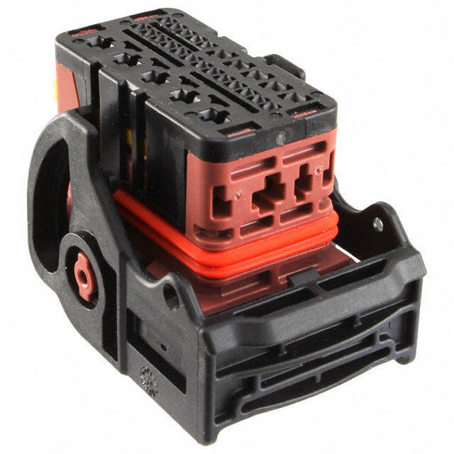
3: Setup and Testing Lab 3: Setup and Testing Lab for 40-Pin DIP PE Platform This is the Setup and Testing lab for the 40-pin DIP version of the PE Kit. If you have the 40-Pin DIP version of the PE Kit (#32305), continue here. If you have the PropStick USB version of the PE Kit (#32306), check for a separate printed Setup and Testing Lab - PropStick USB Version document included with your kit. It is also a free download from www.parallax.com/go/PEKit. The PE Platform The Propeller Education (PE) Kit Platform shown in Figure 3-1 makes a great reusable prototyping tool for electronics and robotics projects. It’s also a great starting point for learning the basics of programming the Propeller microcontroller to be the embedded computer brain in your next invention. This lab introduces the 40-Pin DIP PE Platform and its components and features, and then guides you through assembling and testing your PE Platform. Figure 3-1: PE Kit Platform (40-Pin DIP version) The PE Platform in Figure 3-1 is an array of breadboards connected side-by-side with the Propeller chip and support circuits mounted in the center. Each project circuit you build on the left or right breadboards will be adjacent to Propeller chip I/O pins for easy access. Each breadboard also has vertical power connectors on both sides so that ground and regulated 3.3 V are next to any given breadboard row. This arrangement makes most circuits very simple to wire and visually track. It also minimizes the wiring spaghetti and troubleshooting problems that can occur with tall individual breadboards. Propeller Education Kit Labs: Fundamentals · Page 19
Setup and Testing Lab PE Platform Components and Features Figure 3-2 shows the 40-Pin DIP PE Platform’s major components, including: Propeller microcontroller with pin map sticker affixed 9 V battery-to-breadboard connector 5.0 V and 3.3 V voltage regulators LED power indicator Reset button for manual program restarts 5.00 MHz external crystal oscillator for precise clock signal 32 KB EEPROM for non-volatile program storage Propeller Plug programming and communication tool for program downloads and bidirectional communication with the PC. Figure 3-2: PE Kit Platform Components 9 V battery- to- breadboard 3.3 V voltage connector regulator 5.0 V USB Cable voltage regulator LED Power Indicator Propeller Plug programming & Reset communication tool Button Propeller 32 KB EEPROM Microcontroller + 5 MHz Crystal Pin Map Sticker Oscillator Propeller Microcontroller A Propeller Microcontroller in a 40-pin DIP package provides a breadboard friendly brain for the PE Platform. This amazing microcontroller has eight processors, called cogs. Its system clock can run at up to 80 MHz, and each cog can execute up to 20 million instructions per second (MIPS). Each cog takes turns at accessing the Propeller chip’s main memory. This memory access combined with the Spin (high level) and Assembly (low level) languages created especially for the Propeller makes writing code for multiple processors very simple and straightforward. If you’ve ever written a BASIC subroutine and subroutine call (or a C function and function call, or a Java method and method call), making a different processor execute that subroutine/function/method takes just two more steps. You’ll see lots of examples of this as you go through the PE Kit Labs. Propeller Datasheet and Propeller Manual The Propeller Datasheet provides a complete technical description of the Propeller microcontroller, and the Propeller Manual explains the chip’s programming software and languages in detail. Both the Propeller Datasheet and Propeller Manual are included in PDF form in the Propeller Tool software. The printed version of the Propeller Manual is also available for purchase at www.parallax.com (#122-32000). Page 20 · Propeller Education Kit Labs: Fundamentals
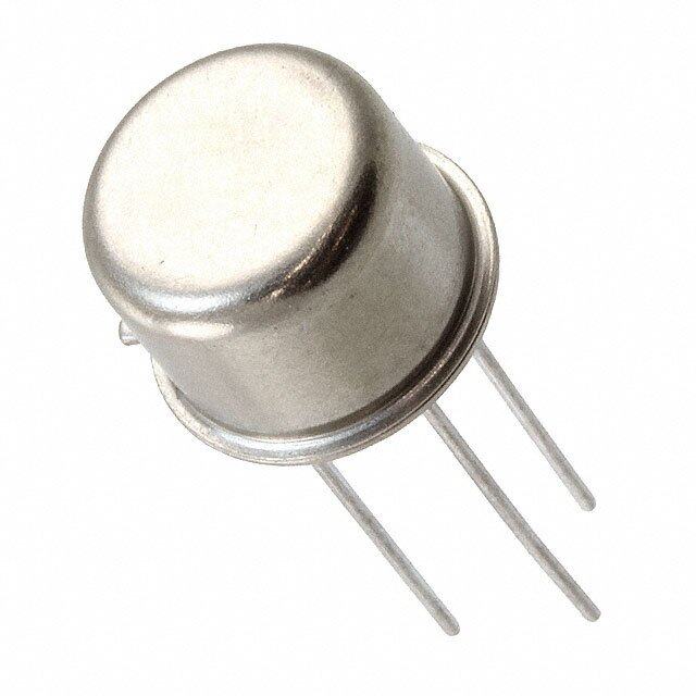
3: Setup and Testing Lab Reset Button The reset button can be pressed and released to restart program execution. It can also be pressed and held to halt program execution. When released, the Propeller chip will load the program stored in PE Platform’s EEPROM program and restart from the beginning. 9 V Battery-to-Breadboard Connector This little gadget provides a simple, breadboard-friendly power supply connection. The recommended DC supply voltage across VIN–VSS is 6 to 9.5 VDC, and recommended power sources for VIN−VSS include: 9 V alkaline batteries Rechargeable 9 V batteries (common voltage ratings include 9 V, 8.4 V, and 7.2 V) Always disconnect the battery from the connector and store separately. 9 V batteries should never be stored in the same box as the PE Kit platform or components because loose parts could short across the terminals. The 9 V battery should always be disconnected from the battery-to-breadboard connector and stored where its terminals cannot short across any metal objects or other conductive materials. “Wall Warts”: The term “wall wart” commonly describes the DC supplies that draw power from AC wall outlets, and they often supply a much higher DC voltage than they are rated for. If you are going to use a wall wart, it’s usually best to choose one that’s rated for 6 V regulated DC output with a current capacity of 500 mA or more. The PE DIP Plus kit includes a 47 µF capacitor that can be placed across the battery inputs on the breadboard to provide the input capacitance required by the PE Platform’s voltage regulator due to the wall wart’s longer supply line. 5.0 V Regulator The National Semiconductor LM2940CT-5.0 regulator is included in the PE Platform to make it convenient to supply 5 V components, such as the infrared detector introduced in the Counter Modules and Circuit Applications lab. A series resistor (typically 10 kΩ) should always be connected between a 5 V output and a Propeller I/O pin, which is 3.3 V. The 5 V regulator also serves as an intermediate stage between the battery input voltage and the 3.3 V regulator that supplies the Propeller chip. The LM2940 voltage regulator circuit is designed to provide a 400 mA output current budget with a 9 V battery supply in the classroom or lab (at room temperature). This current budget can vary with supply voltage and temperature. For example, if the supply voltage reduced from 9 V to 7.5 V, the current budget increases to nearly 700 mA at room temperature. Another example, if the supply voltage is 9 V, but the ambient temperature is 100 F (40 C), the current budget drops to around 350 mA. More Info: Appendix E: LM2940CT-5.0 Current Limit Calculations beginning on page 227 includes equations you can use to predict the PE Kit’s 5 V regulator circuit’s current budgets under various supply voltage and temperature conditions. The LM2940CT datasheet, available from www.national.com, has lots more information, including pointers for attaching a heatsink to the LM2940 to increases its current/temperature budget by improving its ability to dissipate heat 3.3 V Regulator This National Semiconductor LM2937ET-3.3 regulator can draw up to 400 mA from the PE Platform’s LM2940 (5 V regulator) at room temperature and supply the 3.3 V system with up to 360 mA of current. The 3.3 V system includes the Propeller chip, EEPROM, power LED, and the variety of 3.3 V circuits you will build in the PE Kit Labs. Propeller Education Kit Labs: Fundamentals · Page 21
Setup and Testing Lab Keep in mind that if you have a power-hungry 5 V circuit, it subtracts current from the 5 V regulator’s 400 mA output current budget, which in turn leaves the 3.3 V regulator with a smaller current budget to supply the rest of the system. LED Power Indicator This light turns on to indicate that power is connected to the board. It can also provide indications of dead batteries, short circuits, and even tell you if the Propeller Plug programming and communication tool is connected. As wired in this lab, it draws about 12 mA. After completing this lab, you can use a larger resistor for a less-bright indicator light that draws less current. 5.00 MHz Crystal Oscillator and Socket The 5.00 MHz crystal oscillator provides the Propeller chip with a precise clock signal that can be used for time-sensitive applications such as serial communication, RC decay measurements and servo control. The Propeller chip has built-in phase locked loop circuitry that can use the 5.00 MHz oscillator signal to generate system clock frequencies of 5, 10, 40 or even 80 MHz. The 5.00 MHz oscillator can also be replaced with a variety of other oscillators. A few examples include a programmable oscillator and a 60 MHz crystal. The Propeller chip also has a built-in RC oscillator that can be used in fast or slow modes (approximately 12 MHz and 20 kHz respectively). The internal oscillators are not nearly as precise as the 5.00 MHz oscillator, so if your project involves time-sensitive tasks such as serial communication, pulse width modulation for servo control, or TV signal generation, make sure to use the external 5.00 MHz oscillator. 32 KB EEPROM The PE Platform’s 32 KB EEPROM program and data storage memory is non-volatile, meaning it can’t be erased by pressing and releasing the reset button or disconnecting and reconnecting power. This EEPROM memory should not be treated like RAM because each of its memory cells is only good for 1 million erase/write cycles. After that, the cell can actually wear out and no longer reliably store values. So, a program that modifies an EEPROM cell once every second would wear it out in only 11.6 days. On the other hand, if a cell gets modified every ten minutes, it’ll be good for over 19 years. EEPROM: Electrically Erasable Programmable Read-Only Memory RAM: Random Access Memory. Keep in mind that your application can use the Propeller chip’s main memory (32 KB of which is RAM) for indefinite writes and rewrites at any frequency. It can then use the EEPROM to back up data that the application may need later, especially if that data has to live through disconnecting and reconnecting power. The EEPROM Datalogging Application (available at www.parallax.com → Propeller → Downloads & Articles) introduces an object that can be used to periodically back up values stored in RAM to EEPROM. Propeller Plug Programming and Communication Tool The Propeller Plug provides a serial-over-USB connection between the Propeller chip and PC for programming, communication, and debugging. This tool’s blue LED indicates messages received from the PC, while the red one indicates messages transmitted to the PC. The FTDI chip labeled FT232 on the module converts USB signals from the PC to 3.3 V serial signals for the Propeller chip and vice versa. Page 22 · Propeller Education Kit Labs: Fundamentals
3: Setup and Testing Lab On the PC side, a virtual COM port driver provided by FTDI is bundled with the Propeller Tool software you installed in the previous chapter. Aside from being necessary for the Propeller Tool software to load programs into the Propeller chip, the virtual COM port makes it convenient for the Propeller chip to communicate with serial software such as Parallax Serial Terminal. More Virtual COM Port Info After the FTDI virtual COM Port driver is installed by the Propeller Tool Installer, a Propeller Plug that gets connected to one of the PC’s USB ports appears as a “USB Serial Port (COMXX)” in the Windows Device Manager’s Ports (COM & LPT) list. The FTDI driver converts data placed in the COM port’s serial transmit buffer to USB and sends it to the Propeller Plug’s FT232 chip, and USB messages from the FT232 are converted to serial data and stored in the COM port’s receive buffer. Serial communication software like the Propeller Tool and Parallax Serial Terminal use these COM port buffers to exchange information with peripheral serial devices. Prerequisites Please follow the directions in Software, Documentation & Resources, starting on page 17, before continuing here. Procedure Overview In this lab, you will assemble the PE Platform (40-Pin DIP version), following the steps listed below. It’s important to follow the instructions for each step carefully, especially since you will be wiring up your own development platform (on the breadboard) instead of just plugging the Propeller microcontroller into a socket on a carrier PCB. Inventory Equipment and Parts Assemble the Breadboards Set up PE Platform Wiring and Voltage Regulators Test the PE Platform Wiring Socket the Propeller Chip and EEPROM Connect the Propeller Plug to the PC and PE Platform Connect Battery Power Supply Test Communication Load a Test Program and Test the I/O Pins Troubleshooting for the 40-pin DIP PE Platform Setup (if necessary) Since the PE Platform will be the microcontroller system at the heart of the PE Kit Labs, all its electrical connections should be tested before proceeding to the next lab. By following all the steps in this lab, it will help rule out potential wiring errors, which can easily slip by unnoticed as you build the PE Platform circuits, and then cause unexpected problems in later labs. Propeller Education Kit Labs: Fundamentals · Page 23
Setup and Testing Lab Inventory Equipment and Parts Required: Computer with Microsoft Windows 2000, XP, or Vista and an available USB port 9 V alkaline battery (For this Setup and Testing lab, use a new 9 V, alkaline battery.) PE Kit’s Breadboard Set (#700-32305), Propeller Plug (#32201), and Propeller DIP Plus Kit (130-32305) listed in the tables below Optional, but useful: Small needle-nose pliers and wire cutter/stripper Multimeter (DC + AC Voltmeter and Ohmmeter) Digital storage oscilloscope, such as the Parallax USB Oscilloscope (#28014) Antistatic mat and bracelet ESD Precautions: Electrostatic discharge (ESD) can damage the integrated circuits (ICs) in this kit. If you have an antistatic bracelet and mat, use them. If you don’t, the metal chassis of a PC plugged into a grounded outlet can also provide a safe and convenient way of losing static charge periodically before and while handling ICs. The part of the chassis that’s typically exposed on a PC is the frame on the back. The monitor and peripheral ports are connected to it with metal screws. Touch that frame ! (not the ports) before opening the antistatic bags and then frequently while handling the parts. Here are some more tips for reducing the likelihood of a static zap to PE Kit parts: Avoid touching the metal pins on the ICs. Handle ICs by their black plastic cases. Also, if you know your work area conditions cause you to build up static charge and then zap nearby objects, find another work area that is less static prone. Likewise, if you know a particular sweater causes you to build up charge in a certain chair, don’t wear that sweater while working with the PE Platform. Gather the components listed in Table 3-1, Table 3-2, and Table 3-3. Open up the PE Project Parts bag and check its contents against the PE Project Parts list in Table C-2 in Appendix C: PE Kit Components Listing. Table 3-1: Breadboard Set (#700-32305) Breadboard, 12x30 sockets, 700-00077 3 3.19" x 1.65" Breadboard, 2x24 sockets, 700-00081 4 3.19" x 0.5" Table 3-2: Propeller Plug (#32201) 1 Propeller Plug 805-00010 1 USB A to Mini B Retractable Cable Page 24 · Propeller Education Kit Labs: Fundamentals
3: Setup and Testing Lab Table 3-3: Propeller DIP Plus Kit (130-32305) Part Number Quantity Description 571-32305 1 9 V battery clip 201-01085 2 Capacitor, Electrolytic, 6.3 V, 1000 µF 201-04740 1 Capacitor, Electrolytic, 25 V, 0.47 µF 150-01011 1 Resistor, CF, 5%, 1/4 watt, 100 Ω 150-01030 1 Resistor, CF, 5%, 1/4 watt, 10 kΩ 251-05000 1 Crystal 5.00 MHz, 20 pF, HC-49/µs 350-00001 1 LED Green T1 ¾ 400-00002 1 Pushbutton - normally open 451-03601 1 2-pin m/m header 451-00406 1 Extended right angle m/m 4 pin header with 0.1 spacing 601-00513 1 3.3 V regulator, TO92 package 601-00506 1 5.0 V regulator, TO92 package 602-00032 1 32 kB EEPROM, DIP-8 800-00016 6 Bags of 10 Jumper Wires Propeller Chip P8X32A - 40 pin DIP Propeller DIP pin map sticker P8X32A-D40 1 120-00003 1 Parts and quantities subject to change without notice. Assemble the Breadboards The three 12-column × 30-row prototyping breadboards in Figure 3-3 have sockets whose locations can be described by (column letter, row number). Each column has a letter along the top and bottom of the breadboard and each row has a number along the sides. Two examples of breadboard coordinates in the figure are (K, 3) on the center breadboard, and (C, 7) on the right breadboard. Each breadboard is organized in rows of six sockets; all the sockets in each row of six are connected by a metal bracket underneath. So, to connect two or more wires together, just plug them into the same row of six sockets. Propeller Education Kit Labs: Fundamentals · Page 25
Setup and Testing Lab Connect the interlocking breadboards together as shown in Figure 3-3. Figure 3-3: Breadboards Example coordinate: Each group of six sockets (K, 3) on center breadboard is electrically connected. Example coordinate: (C, 7) on right breadboard Two groups of 12 sockets All 24 sockets next to each Example coordinate: Example coordinate: by each red line are black line are electrically (BLACK, 22) on middle- (RED, 28) on right power electrically connected. connected. right power connector connector See it in color and zoom in: This file is available in color as a free PDF download from www.parallax.com/go/PEKit. You can also use Adobe Acrobat Reader to zoom in on regions of the various wiring diagrams, which can be useful for verifying where certain leads get plugged in. Adhesive Backing - don’t expose it. The breadboards have an adhesive backing covered with wax paper. Do not peel off the wax paper unless you are ready to permanently affix the breadboards to something permanent, such as a metal back plane cut to size or a project box. VSS and GND; VDD and 3.3V: The Propeller chip’s GND pin is referred to as VSS in the Propeller Manual, and VDD is +3.3 V. Each breadboard in Figure 3-3 is flanked on both sides by a 2-column × 24-row power connector. The columns on these power connectors are indicated by black and red lines, and the rows are indicated by the breadboard row numbers. Example coordinates include (BLACK, 22) on the middle- right power connector and (RED, 28) on the right one. On each power connector in Figure 3-3, all 24 sockets by the vertical black line are electrically connected. These sockets typically serve as a common ground, and each of these black columns gets connected to the battery’s negative terminal on the PE Platform. Each power connector also has two groups of twelve sockets denoted by two vertical red lines. The upper twelve sockets next to the red line are grouped together, but are not connected to the lower twelve next to the other red line. The break in the red line by these socket groups indicates the break in continuity. The breadboard is designed this way to accommodate two separate voltage supplies on the same power connector. This Page 26 · Propeller Education Kit Labs: Fundamentals
3: Setup and Testing Lab feature is not used now, so all the positive power connectors are shorted together with jumper wires, and then connected to the 3.3 V regulator’s output to provide a supply for the PE Platform. Set up PE Platform Wiring and Voltage Regulators The PE Platform schematic shown in Figure 3-4 will be assembled in steps. In this section, you will first set up and test the wiring without the battery, Propeller Plug, Propeller chip or 24LC256 EEPROM. After some electrical tests to verify the wiring, you will connect and test each component. By following this procedure, you will minimize the likelihood of damaging one of the components due to a wiring error. Figure 3-4: Schematic – Propeller DIP Plus Kit Figure 3-5 shows the wiring diagram we will use for the schematic in Figure 3-4. Note that the Propeller chip, 24LC256 EEPROM, Propeller plug and battery are not yet connected. Note also that the board in the wiring diagram is tight-wired, with all the wires cut to length to be flush with the breadboard surface. This will make it easier to identify and remove loose-wired project circuits without having to worry about potentially disconnecting a part or wire that’s integral to the PE Platform. Make sure your breadboard is oriented so that the numbers and letters that indicate the breadboard socket coordinates are the same as in Figure 3-5. Propeller Education Kit Labs: Fundamentals · Page 27
Setup and Testing Lab Connect the wires and components exactly as shown in Figure 3-5. Make sure that the all of the wires are securely plugged into their sockets. If you accidentally cut a wire too short and it has a tenuous connection in the socket, discard it and replace it with one you have cut to the correct length. The LED’s anode should be connected to (RED, 10) and its cathode to (L, 10). The cathode pin is the one closer to the flat spot on the otherwise round rim at the base of the LED. The resistor across (K, 9) and (K, 10) is 100 Ω (brown-black-brown) and provides series resistance for the power LED. The resistor across (D, 5) and (D, 9) is 10 kΩ (brown-black-orange), and will pull up one of the EEPROM pins. Figure 3-5: Wiring Diagram – Propeller DIP Plus Kit before ICs are Connected Verify Wiring Connections It’s important to eliminate any wiring mistakes before connecting power to the PE Platform. By double-checking your wiring and running a few simple tests, you can in many cases catch a mistake that might otherwise cause your system not to work or even damage some of its components. Although the PE Platform’s parts are not expensive to replace, unless you have extras on hand, waiting while the new parts get shipped could turn out to be an unwelcome delay. Make a printout of Figure 3-5, and verify each connection by drawing over it with a highlighter pen after you have checked your wiring against the diagram, matching the coordinates of each socket that a part or wire is plugged into against the coordinates shown in the figure. Page 28 · Propeller Education Kit Labs: Fundamentals
3: Setup and Testing Lab The 9 V battery’s red positive terminal wire should be plugged into the center breadboard’s (L, 1) socket, and its black negative terminal plugs into (L, 2). The LM2940-5.0 voltage regulator in sockets (J, 1-3) should be plugged in so that the labeling on the black case faces left, and the heat conducting metal tab and backing faces right. The LM2937-3.3 voltage regulator in sockets (H, 3-5) should also be plugged in so that the labeling on the black case faces left, and the heat conducting metal tab and backing faces right. Verify that the LM2940 5 V regulator’s output capacitor’s negative terminal (find the stripe with the minus “–” signs on its metal case) is connected to (BLACK, 1) and that the LM2937 3 V regulator’s output capacitor’s negative terminal is plugged into either (J, 6) or (J, 7). WARNING: Reverse voltage across an electrolytic capacitor can cause it to rupture or ! in some cases explode. The electrolytic capacitor’s negative terminals (denoted by a stripe with negative signs) should always be connected to a lower voltage than its positive terminal. Verify that the Power LED’s anode terminal is connected to (RED, 10) and that its cathode terminal (indicated by the shorter lead and flat spot on the otherwise cylindrical plastic case) is connected to (L, 10). Test the PE Platform Wiring This section has a list of test points that you can probe with a multimeter to verify that: The voltage regulators are correctly wired and working properly The supply voltages are correctly distributed to all the power rails The supply voltages are routed to the correct sockets to supply the Propeller and EEPROM chips. If you have a multimeter at your disposal, the test points are listed below. Tests Points with Battery Disconnected Continuity Most multimeters have a continuity setting that allows you to probe for low resistances. The symbol for continuity test is typically a diode with a dot emitting sound waves, indicating that if the meter detects low resistance, it will play a tone. If your meter does not have a continuity test mode, consider measurements under 1 Ω as an indication of continuity. Resistance measurements tend to vary with length of wire. For example, the resistance between (RED, 30) on the far left power connector and (RED, 30) on the far right power connector might measure in the 0.5 Ω range, while if you measure two points on the same power connector, it might measure almost nothing. The measurement will depend on your meter’s calibration and probe resistance. You can find out what zero ohms should be by shorting your probes together. If a pair of test points below fail the continuity test, look for missing jumper wires and loose connections on the center board and rails. Propeller Education Kit Labs: Fundamentals · Page 29
Setup and Testing Lab Battery clip’s negative terminal sockets to the BLACK columns in all four power connectors. (The negative terminal on the battery clip is the smaller diameter terminal that’s closer to the wires.) Battery clip’s positive terminal to the center board’s (G, 1) Battery clip’s negative terminal to the following sockets: (G, 19), (G, 20), (F, 22), (D, 4), (F, 7), (G, 6, 7, 8, 9), (G, 2), and (K, 4). (I, 5) to (RED, 13) and (RED, 18) on all four power connectors. (RED, 18) to: (F, 19), (G, 22), (B, 5,), and (B, 6). Tests with Battery Connected If your voltmeter is pretty accurate, measured voltages will typically fall in the ± 0.1 VDC range. Some inexpensive voltmeters out there have much lower accuracy. If you are using a very inexpensive voltmeter, or one with an unknown history, you may notice somewhat larger measurement variations. The 0.47 µF capacitor should be placed across the 9 V power input if you are using a 6-9 VDC supply that plugs into the wall, or any supply wire that’s longer than 9 V battery-to-breadboard adapter that comes in the kit. Connect a new alkaline or freshly charged rechargeable 9 V battery to the PE Platform’s battery clip. The power LED should glow brightly. If it does not, or if the green LED takes glows orange instead of green, disconnect the battery immediately and go to Troubleshooting entry (2) on page 41. DC Voltage Test the voltage across the four red/black vertical power rails. The voltage across (RED, 13) and (BLACK, 13) should measure 3.3 VDC on each of the four power connectors. If the voltage is instead in the 4 V neighborhood or higher, disconnect power immediately and go to Troubleshooting entry (11) on page 44. If the voltage is otherwise incorrect, go to Troubleshooting entry (3) on page 42. Repeat the 3.3 VDC test for (RED, 18) and (BLACK, 13). (I, 1) on center breadboard to (BLACK, any): same as voltage across battery terminals. (G, 3) on center breadboard to (BLACK, any): 5 VDC. . If the voltage is instead in the 6 V neighborhood or higher, disconnect power immediately and see Troubleshooting entry (11) on page 44. Socket the Propeller Chip and EEPROM Figure 3-6 shows the PE Platform Schematic after the Propeller chip and EEPROM have been socketed. Disconnect the battery from the clip for the next steps. Identify the reference notch on the Propeller chip and pin map sticker, and compare their orientation to the reference notch on the pin map sticker in Figure 3-6. (The reference notch is the semicircle between the P0 and P31 labels on the pin map sticker, and it should correspond to an actual notch in the Propeller chip at the same location.) Affix the pin map sticker to the Propeller chip, making sure that the reference notch on the sticker is oriented the same way as the reference notch on the chip. Make sure that each pin is aligned with the correct breadboard socket it’s going to get pressed into. Page 30 · Propeller Education Kit Labs: Fundamentals
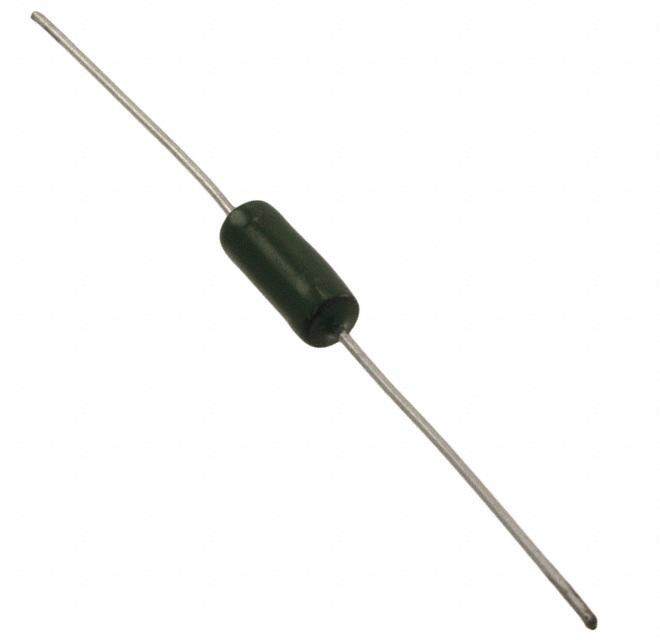
3: Setup and Testing Lab Plug the Propeller chip into the breadboard, verifying its orientation against Figure 3-6. Press firmly with two thumbs. Find the reference notch on the 24LC256 EEPROM chip, then orient it as shown in Figure 3-6 and plug it in. The reference notch should be between the pins that are in the (F, 6) and (G, 6) sockets. Figure 3-6: Wiring Diagram – Propeller DIP Plus Kit Connect the Propeller Plug to the PC and PE Platform The Propeller Tool software should be loaded on your PC before starting here. If you have not already done so, complete the Software, Documentation & Resources lab, starting on page 17 before continuing here. The first time you connect your Propeller Plug to your PC with a USB cable, two things should happen: 1) The Propeller Plug’s serial transmit and receive LEDs should flicker briefly. 2) The Windows operating system should display the message “Found New Hardware – USB Serial Port” followed by “Found New Hardware – Your new hardware is installed and ready to use.” Each time you reconnect your Propeller Plug to the PC, the communication LEDs should flicker, but Windows typically does not display the serial port installation messages again after the first time. The battery should still be disconnected. Propeller Education Kit Labs: Fundamentals · Page 31
Setup and Testing Lab Connect the Propeller Plug to your computer with the USB cable, and verify that both of the Propeller Plug’s communication LEDs (red and blue) flicker briefly immediately after you make the connection. Now, connect the Propeller Plug to the 4-pin header in your PE Platform parts side up as shown in Figure 3-6. Verify that the power indicator LED that’s plugged into the (RED, 10) and (L, 10) sockets glows faintly. You may have to look straight down on its dome top to see the glow. If the power LED does not glow faintly, do not proceed to the next step. Instead, go to Troubleshooting entry (5) on page 42. Connect Battery Power Supply When you connect the battery supply, the power LED that glowed faintly when you connected the Propeller Plug should glow brightly. This indicates that the PE Platform’s 3.3 V regulator is supplying 3.3 V power to the PE Platform’s Propeller chip, EEPROM, and sockets next to the red stripes on the power connectors. Connect the battery to the battery clip as shown in Figure 3-6. The PE Platform’s power LED should glow brightly. If it does not, unplug the battery immediately and go to Troubleshooting entry (4) on page 42. The same applies if the green power LED takes on an orange hue. If you have a voltmeter, test the voltage at the red and black power connectors. Each should now measure 3.3 VDC. If the voltage is incorrect, disconnect the battery and go to Troubleshooting entry (3) on page 42. Check the AC voltage across the red and black power connectors. There should only be about 50 mV of AC voltage. For AC voltages greater than 300 mV, go to Troubleshooting entry (11) on page 44. Test Communication The Propeller Tool software’s Identify Hardware feature can be used to verify communication between the PC and the Propeller chip. Make sure that the battery is connected. Verity that the USB cable connects the PC to the Propeller Plug. Verify that the Propeller Plug is connected to the 4-pin header parts side up (label side down). Open the Propeller Tool software, click the Run menu select Identify Hardware…(or F7). If the Propeller Tool reports, “Propeller Chip version 1 found on COM…”, continue to the next section (Load a Test Program and Test the I/O Pins). Otherwise, go to Troubleshooting entry (6) on page 42 and Troubleshooting entry (1) on page 39. Load a Test Program and Test the I/O Pins These tests are important before proceeding with the PE Kit labs. One example of a problem these tests can intercept is a bent I/O pin on the Propeller chip. Occasionally, one of the pins gets bent underneath the Propeller chip instead of sinking into its breadboard socket. It can be difficult to catch by visual inspection, but if an I/O pin does not sense inputs or control outputs, these tests will lead to finding the problem quickly. It might otherwise take a lot of time looking for an error in an application circuit or the accompanying code before discovering a bent pin is the culprit. So follow along and perform these tests. It won’t take long, and it could end up saving you a lot of time later. Page 32 · Propeller Education Kit Labs: Fundamentals
3: Setup and Testing Lab I/O Pin Test Circuit Parts Open up the PE Project Parts bag and check its contents against the PE Project Parts list in Table C-2 in Appendix C: PE Kit Components Listing. For the next test circuits, gather the following parts from the PE Project Parts bag: (1) LED - Red, green or yellow (2) Resistors – 100 Ω (brown-black-brown) (1) Resistor – 10 kΩ (brown-black-orange) (1) Pushbutton (4) Jumper wires Build the Test Circuit The circuit shown in Figure 3-7 and Figure 3-8 will provide a means of testing the Propeller chip’s I/O pins as both inputs and outputs. If any of the checklist instructions do not work, go to Troubleshooting entry (9) on page 43. Start by verifying that the LED circuit is correct and that all the power connector sockets by the red vertical lines supply 3.3 V as follows: Disconnect the battery from the battery clip. Build the circuit shown in Figure 3-7 and Figure 3-8. Reconnect the battery to the battery clip. The LED circuit can be tested by connecting it to one of the power connector rails’ RED sockets, which should supply it with 3.3 VDC. Disconnect the LED wire from (L, 14) in Figure 3-8, and plug it into (RED, 13) on the power connector between the center and left prototyping breadboards. The LED should light. If it doesn’t, double-check your wiring. First, make sure the LED is not plugged in backwards. Its shorter (cathode) leg should be plugged into a socket next to the black line on the left power connector. Figure 3-7: Test Circuit Schematic Propeller Education Kit Labs: Fundamentals · Page 33
Setup and Testing Lab Figure 3-8: Test Circuit Wiring Diagram The LED circuit can also be used to test and make sure all the RED power rails are connected to the 3.3 V supply. If you already did that with a voltmeter, skip this checklist instruction. Unplug the wire from (RED, 13), and plug it into (RED, 12) on the leftmost power connector. The LED should glow again. Repeat for (RED, 18) on the leftmost power connector as well as (RED, 18) on the middle-left power connector. The LED should glow at each test point. If not, check your board against the wiring diagram in Figure 3-8 for missing jumper wires between RED power connector sockets. After testing the LED circuit and power connectors, the LED should be reconnected to the Propeller I/O pin so that it can be used in conjunction with a test program to indicate that I/O pins are functioning properly as outputs. Reconnect the LED circuit to the Propeller chip’s P3 I/O pin (L, 14) in Figure 3-8. Test Program – PushbuttonLedTest.spin As written, PushbuttonLedTest.spin flashes an LED connected to any I/O pin on the Propeller chip’s left side (P0 to P15). The rate the LED flashes depends on whether or not the pushbutton connected to P18 is pressed (10 Hz) or not pressed (2 Hz). The wire connecting P3 to the LED circuit can be used to probe each I/O pin. For example, if that wire is instead connected to (L, 11), it confirms that P0 is functioning as an output if it makes the LED blink. Connect the wire to (L, 12), and it confirms, P1 is functioning, and so on, up through P15 (L, 30). You can use the pin map sticker on your Propeller chip to quickly and easily locate I/O pins. I/O pin is an abbreviation for input/output pin. The direction and state of each I/O pin is controlled by the program. Programs can set and modify the directions and states of individual I/O pins as well as groups of I/O pins at any time. Page 34 · Propeller Education Kit Labs: Fundamentals
3: Setup and Testing Lab If the LED blinks at 2 Hz while the pushbutton is pressed and held, and blinks at 10 Hz after it is released, it confirms that P18 is functioning as an input. The program can then be modified and the wire connecting P18 to the pushbutton can be moved to each I/O pin on the right side of the Propeller chip to test those I/O pins as inputs. After all the outputs on the Propeller chip’s left side and all the inputs on its right side have been tested, the pushbutton can then be moved to the left side and the LED to the right. Then, the test can be repeated to verify that all I/O pins on the left function as inputs and the pins on the right function as outputs. Load PushButtonLedTest.spin into EEPROM You can load this program into the PE Platform’s EEPROM memory by clicking the Run menu, selecting Compile Current, and then Load EEPROM (F11). After the program is loaded into EEPROM, the Propeller chip copies it from EEPROM into its main memory RAM and one of the Propeller chip’s processors starts executing it. (If you disconnect and reconnect power or press and release the PE Platform’s reset button, the Propeller chip will reload the program from EEPROM into main memory and start running it from the beginning.) Open PushbuttonLedTest.spin into the Propeller Tool, or type it in. If you type it, be careful to indent each line exactly as shown. Click the Propeller Tool’s Run menu and select Compile Current → Load EEPROM (F11). The Propeller Communication window will appear briefly and display progress as the program loads. If it closes after the “Verifying EEPROM” message, then the download was successful. Propeller Education Kit Labs: Fundamentals · Page 35
Setup and Testing Lab If instead an error window opens that reads “EEPROM programming error...” refer to Troubleshooting entry (8) on page 43. Verify that the LED connected to P3 flashes on/off rapidly, at 10 Hz. Press and hold the pushbutton down, and verify that the LED flashes slower, at only 2 Hz. If everything worked as anticipated, go on to I/O Pin Tests below. If it did not work, go to Troubleshooting entry (9) on page 43. I/O Pin Tests Use the pin map sticker on the Propeller chip to locate Propeller I/O pins. If any of these tests indicate that an I/O pin is faulty, refer to Troubleshooting entry (10) on page 43. The first step is to use the LED circuit to verify that each I/O pin on the left side of the Propeller chip functions as an output. Unplug the end of the wire that’s in (L, 14) and use it probe P0 through P15. (L, 11) through (L, 18) and (L, 23) through (L, 30). Each I/O pin should cause the LED circuit to blink. Next, use the Pushbutton circuit to verify that each I/O pin on the right side of the Propeller chip functions as an input. Press and hold the pushbutton on the right breadboard. The LED circuit on the left breadboard should flash at 2 Hz instead of 10 Hz. Disconnect the battery from the battery clip. Unplug the pushbutton wire at P18, (A, 28) on the center breadboard, and plug it into P16 (A, 30). Modify the program to monitor P16 instead of P18 by changing the PUSHBUTTON CON directive in the PushButtonLedTest.spin object from 18 to 16. Reconnect the battery to the battery clip. Load the modified program into RAM by clicking the Run menu and selecting Compile Current → Load RAM (F10). Verify that the pushbutton, which is now connected to P16, controls the LED frequency. Repeat this procedure for P17, P19, P20, and so on, up through P27. Load RAM (F10) vs. Load EEPROM (F11): The Propeller Tool software’s Load RAM feature is fast, but the program gets erased whenever power gets disconnected/reconnected or the PE Platform’s reset button gets pressed. After a reset, the Propeller chip will load the program most recently loaded into EEPROM and start executing it. While programs loaded into EEPROM do not get erased, they take longer to load. Since testing the pushbutton involves iteratively changing and reloading the program into the Propeller chip, it saves time to use Load RAM. What about testing P28..P31? These Propeller I/O pins are hardwired to the FTDI USB → serial chip and EEPROM program memory. If you were able to use the Load EEPROM feature it confirms that these I/O pins are fully functional. While it’s true that these pins can be used with some application circuits, you would need to make sure that the application circuits will not damage and cannot be damaged by the other circuits connected to P28..P31. See Figure 3-4 on page 27 for details. For the most part, the PE Kit labs will not use these I/O pins for application circuits. At this point, half of the Propeller chip’s I/O pins have been tested as outputs, and the other half have been tested as inputs. Before moving the test circuits to opposite sides of the board, it’s a good idea to load an empty program into the PE Platform’s EEPROM so that the Propeller chip won’t send signals to the wrong I/O pins. The power should be disconnected when the circuit is changed. To make sure the empty program runs automatically when the power gets reconnected, it should be loaded into EEPROM using F11. Load this program (DoNothing.spin) into EEPROM (F11): Page 36 · Propeller Education Kit Labs: Fundamentals
3: Setup and Testing Lab '' File: DoNothing.spin PUB main ' Empty main method Now, power can be disconnected, the pushbutton can be moved to the left breadboard, and the LED circuit can be moved to the right breadboard. Disconnect the battery and USB cable. Move the LED circuit to the right breadboard and connect it to P16. Move the pushbutton to the left breadboard and connect it to P15. Modify the object PushbuttonLedTest.spin as follows: o Change the LEDs_START CON directive from 0 to 16. o Change the LEDs_END CON directive from 15 to 27. o Change the PUSHBUTTON CON directive to 15. Reconnect the USB cable and battery. Load the modified PushbuttonLedTest.spin object into EEPROM using F11. Repeat the output LED tests for P16 to P27. Repeat the input pushbutton tests starting at P15, then P14, and so on through P0. Remember to modify the code, and then load RAM using F10 between each test. Before Changing or Adjusting Circuits The program DoNothing.spin causes all the I/O pins to be set to input, ensuring that it cannot inadvertently send a high (3.3 V) signal to a circuit that’s sending a low (0 V) signal, or vice versa. When you are finished testing, it’s a good idea to load the DoNothing.spin object back into EEPROM so that your Propeller chip cannot damage the next circuit that gets connected to it. In fact, make it a habit. Always load DoNothing.spin into EEPROM using F11 before disconnecting power and building a new circuit or making changes to an existing one. Load DoNothing.spin into EEPROM (F11) now. When you reconnect power, DoNothing.spin will automatically load from EEPROM to Propeller main memory, and the Propeller chip will execute it. It will set all I/O pins to input by default. Then, the program ends, and the Propeller chip goes into low power mode. This protects the Propeller chip and your new circuit from the time you turn power back on until the time you load the program for your new circuit into the Propeller chip. Propeller Supply Voltage Regulation – It’s Important! A stable voltage supply is important because many different application circuits and subsystems depend on it. Any voltage supply fluctuations will translate directly into fluctuations in 3.3 V high signals sent by Propeller I/O pins. They also translate into fluctuations in Propeller I/O pin threshold voltage, which in the Propeller is approximately ½ of the 3.3 V supply voltage. When voltage is applied to a Propeller I/O pin set to input, the Propeller interprets it as binary-1 if that voltage is above the threshold or binary-0 if it’s below. I/O pin high and low signal levels and input threshold voltage are also used in a variety of analog to digital (voltage measurement) and digital to analog (voltage synthesis) applications. So any supply voltage fluctuations that affect output-high and input threshold voltage levels also reduce the accuracy of both voltage measurement and synthesis. Products and prototyping printed circuit boards designed with Propeller chips typically have several features to improve supply voltage stability. The voltage regulator output is usually very close to the Propeller chip’s supply inputs—the 3.3V and GND pins. Depending on the diagram, you might also Propeller Education Kit Labs: Fundamentals · Page 37
Setup and Testing Lab see them labeled Vdd and Vss. The metal traces on the board that connect the voltage regulator to the Propeller’s supply inputs are also typically wider than other traces that transmit signals. Since even metal conductors have a small amount of resistance, these measures minimize the resistance between the voltage regulator’s output and the Propeller chip’s supply inputs. This in turn improves supply voltage stability by minimizing voltage fluctuations that can occur if Propeller current consumption fluctuates, which can in turn occur when processors (cogs) launch and when I/O pins that drive loads switch on and off. Capacitors can also be connected across the Propeller chip’s supply inputs to provide additional protection from voltage fluctuations and further improve supply voltage stability. Improve PE Kit Supply Voltage Stability Compared to products and prototyping boards, the distances between the PE Platform’s voltage regulator outputs and Propeller chip supply inputs are quite large, and this can reduce voltage stability. That’s bad. The remedy is simple, and only requires two capacitors and two wires. That’s good. The wires connect the supply inputs on opposite sides of the chip to each other to ensure that the supply voltage levels are identical at both input terminals. The capacitors are placed across the 3.3 V and GND supply input terminals on both sides of the Propeller chip to filter out any voltage fluctuations caused by the long supply lines. Parts List: (2) Jumper Wires (2) Capacitors – 0.1 μF (from the PE Kit Project Parts bag) Procedure: Figure 3-9 shows the jumper wire and capacitor connections. The Propeller chip’s 3.3 V supply pins are connected to each other with one jumper wire, and the GND pins are connected with a second jumper wire. 0.1 μF capacitors are then connected across the Propeller chip’s 3.3 V and GND pins on both sides. Disconnect power and programming port Trim the two jumper wires to reduce any excess wire length when connected as shown in Figure 3-9. Use a red jumper wire to connect (J, 22) to (D, 19). Use a black jumper wire to connect (J, 20) to (D, 22). Plug the leads of one 0.1 μF capacitor into (K, 22) and (J, 19). Plug the leads of the other 0.1 μF capacitor into (B, 19) and (B, 22). Double-check your wiring. Reconnect power and programming port. Figure 3-9: Close-up View of Supply Input Strap and Filter Capacitor Connections Page 38 · Propeller Education Kit Labs: Fundamentals
3: Setup and Testing Lab Troubleshooting for the 40-Pin DIP PE Platform Setup (1) Programming Connection and Serial Port a. When you connect the Propeller plug to the USB port, the red and blue LEDs next to the Propeller Plug’s mini B connector should flicker briefly. If not, try a different port. If none of the ports result in this response, contact Parallax technical support. (See Tech Support Resources on page 18.) b. Run the Propeller Tool, click the Run menu and select Identify Hardware (F7). If you get the message shown in Figure 3-10: i. Make sure the USB cable is connected to both the Propeller Plug and your computer’s USB port. ii. Check the following jumper wires on your PE Platform: (D, 3) to (D, 10), (F, 10) to (F, 21), (B, 1) to (B, 12), and (C, 2) to (C, 11) iii. Also, make sure the battery is connected and that the PE Platform’s green power LED is glowing brightly. Then, try F7 again. iv. If that does not correct the problem, try connecting the cable to a different USB port on your computer. Figure 3-10: Communication Error Message c. If you still get the Figure 3-10 message after ensuring that the USB cable is connected: i. Click the Communication Error message box’s Edit Ports button. The Serial Port Search List window in should appear. You can also access this utility by clicking the Edit menu and selecting Preferences (F5). Click the Operation tab and then click the Edit Ports button. ii. Leave the USB cable plugged into the Propeller Plug and unplug and re-plug the USB cable into the PC’s USB port. Wait about 20 seconds between disconnecting and reconnecting the USB cable. The list should update and show a new “USB Serial Port” entry like the COM46 line in Figure 3-11. iii. If it appears in light gray print, right-click the entry and select Include Port (COMX), or in some cases Re-Include Port. Propeller Education Kit Labs: Fundamentals · Page 39
Setup and Testing Lab Figure 3-11: Serial Port Search List d. If the serial port search list already does scan for and recognize that port, go to www.parallax.com and click on the USB Driver Installer link at the bottom of the page, and then follow the Troubleshooting link at the bottom of that web page. e. If the Propeller Tool software still displays the “No Propeller chip found…” message, use your Device Manager to locate the USB Serial Port. i. To access the Ports List in the Windows Device Manager, right-click My Computer and select Properties. Click the Hardware tab, and then click the Device Manager Button. In the Device Manager, click the + next to Ports (COM & LPT). ii. Each time you plug in the USB cable, a reference to USB Serial Port (COMXX) should appear, as shown in Figure 3-12. Each time you unplug the cable that connects the Propeller Plug to the PC, the reference should disappear. For example, the Device Manager below shows USB Serial Port (COM 46), which indicates that a Propeller Plug might be connected to COM46. Figure 3-12: Device Manager Ports List Page 40 · Propeller Education Kit Labs: Fundamentals
3: Setup and Testing Lab iii. If the USB Serial Port entry does not appear in the Ports (COM &LPT) list but the Device Manger display appears to refresh every time you plug and unplug the USB cable: 1. It may indicate that the Propeller Plug was plugged into the PC and an attempt to manually install the driver was made before the Propeller Tool software and driver were installed. Browse the list to find the driver that gets added each time you plug in the Propeller Plug. When you find it, uninstall it. You can typically do this by right-clicking the driver and selecting Uninstall. 2. Then, unplug the Propeller Plug. Before plugging it back in, make sure the FTDI USB Driver is installed. The easiest way to do this is to uninstall and reinstall the Propeller Tool. 3. When you reinstall the Propeller Tool software: a. Make sure the checkbox for installing the USB drivers is checked! See the Download Software and Documentation section on page 17 for more information. b. After you have reinstalled the software, the correct driver should automatically get installed when you connect the Propeller Plug to the PC. Make sure to leave the battery disconnected when you connect the Propeller Plug to the PC with the USB cable for the first time. f. Contact Parallax Tech Support. (See page 18.) (2) If the PE Platform’s power LED did not light, or if it glowed orange, when the battery was connected: a. If the power LED glowed orange: i. Check for a short between the LED’s cathode and ground. The LED should have a 100 Ω series resistor between its cathode (L, 10) and ground (BLACK, 9). The resistor should bridge (K, 9) to (K, 10). ii. Check to make sure the voltage at the LED’s anode (RED, 10) is 3.3 V. b. If the LED did not light, it may be plugged in backwards. Check to make sure the cathode is connected to the resistor and the anode is connected to the 3.3 V supply. In terms of Figure 3-5 on page 28, the pin coming out by the flat spot on the otherwise cylindrical base of the LED’s round plastic housing should be plugged into (L, 10). The other (anode lead) should be connected to (RED, 10). See Verify Wiring Connections on page 28 for details. c. Make sure the battery’s (+) terminal is connected to (L, 1) and its (–) terminal is connected to (L, 2). d. There could be a wiring mistake causing a short circuit from one of the supply voltages to ground. If you don’t have a multimeter, start visually checking your wiring again. With a multimeter, you can check the resistance between the battery’s negative terminal, and the three positive supplies. Make sure to disconnect the USB cable and battery before testing resistance. iii. Start by measuring the resistance between the 3.3 V connection and the battery’s negative terminal. For example, test at probe points: (RED, 13) and (J, 4) in the center breadboard. iv. Repeat resistance measurements between the battery’s negative terminal (J, 4) and the 5 V regulated output (G, 3) as well as (J, 4) and the battery input (G, 1). If any of these resistance measurements shows less than 10 Ω, that supply voltage may have been shorted to ground. v. Contact Parallax Tech Support. (See page 18.) Propeller Education Kit Labs: Fundamentals · Page 41
Setup and Testing Lab (3) If the voltage across the power connectors (RED−BLACK) is not 3.3 V: a. If your meter is a lesser-quality model or has been subject to heavy use by other students, check it against a known voltage before trusting its measurements. b. Repeat Verify Wiring Connections section starting on page 28. Carefully continue through Connect Battery Power Supply on page 32, paying close attention to detail, and hopefully you’ll catch the error this time around. These tests can rule out a variety of problems, including shorts with the 5 and/or 9 V supplies. (4) If the Power LED does not light when you plug the battery in after socketing the Propeller chip, but it checked out during previous testing: a. Check for wiring errors to its pins: If a wire terminates at a row that is shared with a Propeller chip or 24LC256 EEPROM pin, it’s a prime suspect. Make sure the socket coordinates are identical to Figure 3-5 on page 28, and Figure 3-6 on page 31. b. Remove the Propeller chip and 24LC256 EEPROM from the breadboard and repeat Verify Wiring Connections on page 28. Continue through Connect Battery Power Supply on page 32 with attention to detail, and hopefully you’ll catch the error this time around. c. Contact Parallax Tech Support. (See page 18.) (5) If the Power LED does not glow faintly after you connect the Propeller Plug to the PE Platforms 4-pin header and to the PC with a USB cable: d. Verify that the resistor in the LED circuit is 100 Ω (brown, black, brown). e. Verify that the power LED’s anode is plugged into (RED, 10), and the cathode is plugged into (L, 10). The cathode is the pin by the flat spot at the base of the otherwise cylindrical plastic case. f. Try the other USB Ports on your PC. g. Try one of the green LEDs from the PE Project Parts kit. The long (anode) pin should plug into (RED, 10), and the shorter (cathode) pin into (L, 10). h. Check all wiring details against Figure 3-5 on page 28, and Figure 3-6 on page 31. i. Remove the Propeller chip and EEPROM from the breadboard and repeat Test the PE Platform Wiring on page 29. Continue through Connect Battery Power Supply on page 32, and hopefully you’ll catch the error this time around. j. Contact Parallax Tech Support. (See page 18.) (6) Common causes of the “No Propeller Chip found…” message are: a. Battery disconnected. Connect the battery. b. Dead battery, battery that needs to get recharged. c. USB cable not connecting Propeller Plug to PC. Make sure both ends are plugged in. d. Propeller Plug not plugged into the 4-pin header, or plugged in upside-down. It should be parts side up (label side down). e. Damaged or worn USB port. Most computers have more than one USB port. Try another port. f. Propeller chip or 24LC256 EEPROM not fully plugged in. The underside of the Propeller chip and 24LC256 EEPROM should both be flush with the top of the breadboard. If not, make sure all the pins are lined up with the breadboard holes, then press down firmly on each chip. g. FTDI USB drivers not installed. See entry (1)in this section. h. Supply voltages – if you didn’t check the voltages with a voltmeter, it’s time to get one and do that. (See Test the PE Platform Wiring on page 29.) If the supply voltages are incorrect, see entry (3). i. Propeller chip plugged in upside down. The semicircle Pin-1 indicator on the Propeller chip sticker shown in Figure 3-6 on page 31 should be adjacent to row 11, not row 30. Page 42 · Propeller Education Kit Labs: Fundamentals
3: Setup and Testing Lab Also, verify that the semicircle notch in the Propeller chip is under the printed semicircle on the sticker, also adjacent to row 11. j. Defective USB Cable. If you have a spare USB A to mini B cable, try it. (7) If the test LED circuit does not light when you plug the jumper wire into (RED, 13): a. The polarity on the LED may be backward. Check to make sure the LED’s cathode is connected to a socket on the power connector next to the black line. b. If the LED did not light when probing the power connector on the left, check to make sure the jumper that that connects the red column in the middle-left power connector to the red column on the far left power connector. (8) If you get an “EEPROM programming error…” message when you use the Propeller Tool’s Load EEPROM feature: a. Check for loose USB and battery connections. b. If the problem persists, try a different USB port. c. If you have a spare USB A to mini B cable, try it. d. The Propeller chip may not be firmly socketed. See Socket the Propeller Chip and EEPROM on page 30. e. Check the following connections: (A, 8) to (A, 14), (A, 9) to (A, 13), (BLACK, 9) to (L, 9), (H, 6) to (H, 7), (I, 7) to (I, 8), (H, 8) to (H, 9), (E, 4) to (E, 7), (RED, 6) to (A, 6), and the 10 kΩ resistor across (D, 5) and (D, 9). See Figure 3-6 on page 31. f. Make sure the 24LC256 is not socketed upside-down. The reference notch on the top- center of the chip should be between (F, 6) and (G, 6). g. If the problem still persists, contact Parallax Tech Support. (See page 18.) (9) If the program downloads, but the test LED circuit does not flash: a. If you hand-entered the program, download it from the Propeller Education Kit page instead. Open it with the Propeller Tool software, and use F11 to download it to EEPROM. This will eliminate the possibility of a typing error during program entry. b. If the LED does not start flashing, check to make sure the oscillator is plugged in to the socket. (See the 5.00 MHz Crystal in Figure 3-2 on page 20 and check Figure 3-5 on page 28 for the correct sockets for connecting the 5.00 MHz oscillator.) c. Remove the oscillator and plug it back in, then re-test. d. Try changing the line in the PushButtonLedTestv1.0.spin that reads _clkmode = xtal1 + pll16x to _clkmode = xtal1 + pll8x. If this change causes the light to start flashing, change it back to pll16x, load this original program back into the Propeller chip and verify that the light won’t flash. If that’s the case, please contact Parallax Tech Support. (See page 18.) (10) Propeller chip I/O pins are factory tested before shipment. If the LED or pushbutton tests indicate a bad I/O pin: a. Take a close look at the pin and verify that it did not miss the socket and bend under the chip’s case. b. Try touching the LED probe lead to the I/O pin. If the light blinks with this electrical contact, but not when it is plugged into an adjacent socket: i. Again, take a look to make sure the pin is not bent under the module. ii. Try unsocketing the Propeller chip, and verify that the pin is not bent. iii. If you have a multimeter, test continuity between the socket the I/O pin was in and the socket the wire was plugged into. If there is no continuity, please contact Parallax Tech Support. (See page 18.) c. If the continuity in the breadboard row is good, and the pin is not bent, plug the Propeller chip back into the breadboard, and test all I/O pins, and take notes on which ones work Propeller Education Kit Labs: Fundamentals · Page 43
Setup and Testing Lab and which ones don’t. Also, make notes of any events you observed during testing, and then contact Parallax Tech Support. (See Tech Support Resources on page 18.) d. Please see the Warranty Policy at www.parallax.com for more information on replacing a module with damaged I/O pins. (11) 4 VDC or more across (RED, any) and (BLACK, any), or 6 VDC or more across (G, 3) to (BLACK, any). a. a. One of the 1000 µF capacitors may not be not properly connected. This is indicated by a DC voltage measurement that is 1 to 2.5 V above what it should be. i. Check to make sure the capacitor leads are inserted into the correct sockets. ii. Check to make sure the capacitor leads are long enough and making sufficient contact with the socket. b. If the voltage across (G, 3) to (BLACK, any) turns out to be 9 V, a wiring mistake may be shorting the battery's positive terminal (G..L, 1) to (G..L, 3). c. If the voltage across (RED, any) and (BLACK, any) measures 9 V, a wiring mistake may be shorting the battery's positive terminal (G..L, 1) to either (G..L, 6) or to one of the red power connectors. d. If the problem still persists, contact Parallax Tech Support. (See page 18.) Page 44 · Propeller Education Kit Labs: Fundamentals
4: I/O and Timing Basics Lab 4: I/O and Timing Basics Lab Introduction Most microcontroller applications involve reading inputs, making decisions, and controlling outputs. They also tend to be timing-sensitive, with the microcontroller determining when inputs are monitored and outputs are updated. The pushbutton circuits in this lab will provide simple outputs that the example applications can monitor with Propeller I/O pins set to input. Likewise, LED circuits will provide a simple and effective means of monitoring Propeller I/O pin outputs and event timing. While this lab’s pushbutton and LED example applications might seem rather simple, they make it possible to clearly present a number of important coding techniques that will be used and reused in later labs. Here is a list of this lab’s example applications and the coding techniques they introduce: Turn an LED on – assigning I/O pin direction and output state Turn groups of LEDs on – group I/O assignments Signal a pushbutton state with an LED – monitoring an input, and setting an output accordingly Signal a group of pushbutton states with LEDs – parallel I/O, monitoring a group of inputs and writing to a group of outputs Synchronized LED on/off signals – event timing based on a register that counts clock ticks Configure the Propeller chip’s system clock – choosing a clock source and configuring the Propeller chip’s Phase-Locked Loop (PLL) frequency multiplier Display on/off patterns – Introduction to more Spin operators commonly used on I/O registers Display binary counts – introductions to several types of operators and conditional looping code block execution Shift a light display – conditional code block execution and shift operations Shift a light display with pushbutton-controlled refresh rate – global and local variables and more conditional code block execution Timekeeping application with binary LED display of seconds – Introduction to synchronized event timing that can function independently of other tasks in a given cog. Prerequisite Labs Setup and Testing Parts List and Schematic This lab will use six LED circuits and three pushbutton circuits. (6) LEDs – 2-each: red, green, yellow (9) Resistors – 100 Ω (3) Resistor – 10 kΩ (3) Pushbutton – normally open (misc) jumper wires Build the schematic shown in Figure 4-1. Propeller Education Kit Labs: Fundamentals · Page 45
I/O and Timing Basics Lab Figure 4-1: LED Pushbutton Schematic Propeller Nomenclature The Propeller microcontroller’s documentation makes frequent references to cogs, Spin, objects, methods, and global and local variables. Here are brief explanations of each term: Cog – a processor inside the Propeller chip. The Propeller chip has eight cogs, making it possible to perform lots of tasks in parallel. The Propeller is like a super-microcontroller with eight high speed 32-bit processors inside. Each internal processor (cog) has access to the Propeller chip’s I/O pins and 32 KB of global RAM. Each cog also has its own 2 KB of RAM that can either run a Spin code interpreter or an assembly language program. Spin language – The Spin language is the high-level programming language created by Parallax for the Propeller chip. Cogs executing Spin code do so by loading a Spin interpreter from the Propeller chip’s ROM. This interpreter fetches and executes Spin command codes that get stored in the Propeller chip’s Global RAM. Propeller cogs can also be programmed in low-level assembly language. Whereas high- level Spin tells a cog what to do, low-level assembly language tells a cog how to do it. Assembly language generates machine codes that reside in a cog’s RAM and get executed directly by the cog. Assembly language programs make it possible to write code that optimizes a cog’s performance; however, it requires a more in-depth understanding of the Propeller chip’s architecture. The PE Kit Fundamentals labs focus on Spin programming. Method – a block of executable Spin commands that has a name, access rule, and can optionally create local (temporary) variables, receive parameters, and return a value. Global and local variables – Global variables are available to all the methods in a given object, and they reserve variable space as long as an application is running. Local variables are defined in a method, can only be used within that method, and only exist while that method executes commands. When it’s done, the memory these local variables used becomes available to other methods and their local variables. Local and global variables are defined with different syntax. Object – an application building block comprised of all the code in a given .spin file. Some Propeller applications use just one object but most use several. Objects have a variety of uses, depending partially on how they are written and partially on how they get configured and used by other objects. Some objects serve as top objects, which provide the starting point where the first command in a given application gets executed. Other objects are written to provide a library of useful methods for top objects or other objects to use. Page 46 · Propeller Education Kit Labs: Fundamentals
4: I/O and Timing Basics Lab Objects can be written to use just one cog, or can include code that gets launched into one or more additional cogs. Some objects have methods that provide a means to exchange information with processes running in other cogs. One object can even make multiple copies of another object, and set each one to a different task. Objects can use other objects, which in turn can use still other objects. In more complex applications, a set of objects will form functional relationships that can be viewed as a file structure with the Propeller Tool’s Object Info window. The examples in this lab only involve single, top-level objects with just one method. Upcoming labs will introduce various building-block techniques for using multiple objects and methods in an application, as well as parallel multiprocessing applications using multiple cogs. Though the objects in this lab are simple, many of them will be modified later to serve as building blocks for other objects and/or future projects. Lights on with Direction and Output Register Bits The LedOnP4 object shown below has a method named LedOn, with commands that instruct a cog in the Propeller chip to set its P4 I/O pin to output-high. This in turn causes the LED in the circuit connected to P4 to emit light. Load LedOnP4 into RAM by clicking Run → Compile Current → Load RAM (or press F10). '' File: LedOnP4.spin PUB LedOn ' Method declaration dira[4] := 1 ' Set P4 to output outa[4] := 1 ' Set P4 high repeat ' Endless loop prevents program from ending How LedOnP4.spin Works The first line in the program is a documentation comment. Single-line documentation comments are denoted by two apostrophes (not a quotation mark) to the left of the documentation text. Click the Documentation radio button above the code in the Propeller Editor. While commands like dira :=… and repeat don’t show in documentation mode, notice that the text to the right of the double apostrophe documentation comments does appear. Notice also that the non- documentation comments in the code, preceded by single apostrophes, do not appear in Documentation mode. Try the other radio buttons and note what elements of the object they do and do not show. Block Comments: There are also documentation block comments that can span multiple lines. They have to begin and end with double-braces like this: {{ block of documentation comments }}. Non-documentation comments can also span multiple lines, beginning and ending with single-braces like this: { block of non- documentation comments }. All Spin language commands that the Propeller chip executes have to be contained within a method block. Every method block has to be declared with at least an access rule and a name. Access rules and method names will be explored in depth in upcoming labs; for now, just keep in mind that PUB LedOn is a method block declaration with a public (PUB) access rule and the name LedOn. Propeller Education Kit Labs: Fundamentals · Page 47
I/O and Timing Basics Lab Bold or not bold? In the discussion paragraphs, the Parallax font used in the Propeller Tool is also used for all text that is part of a program. The portions that are reserved words or operators will be in bold. The portions that are defined by the user, such as method, variable, and constant names and values, will not be in bold text. This mimics the Propeller Tool software’s syntax highlighting Spin scheme. Code listings and snippets are not given the extra bolding. To see the full syntax-highlighted version, view it in the Propeller Tool with the Spin scheme. Go to Edit→ Preferences→ Appearance to find the Syntax Highlighting Scheme menu. The dira register is one of several special purpose registers in cog RAM; you can read and write to the dira register, which stores I/O pin directions for each I/O pin. A 1 in a given dira register bit sets that I/O pin to output; a 0 sets it to input. The symbol “:=” is the Assignment operator; the command dira[4] := 1 assigns the value 1 to the dira register’s Bit 4, which makes P4 an output. When an I/O pin is set to output, the value of its bit in the outa register either sets the I/O pin high (3.3 V) with a 1, or low (0 V) with a 0. The command outa[4] := 1 sets I/O pin P4 high. Since the P4 LED circuit terminates at ground, the result is that the LED emits light. I/O Sharing among Cogs? Each cog has its own I/O Output (outa) and I/O Direction (dira) registers. Since our applications use only one cog, we do not have to worry about two cogs trying to use the same I/O pin for different purposes at the same time. When multiple cogs are used in one application, each I/O pin 's direction and output state is the "wired--OR" of the entire cogs collective. How this works logically is described in the I/O Pin section in Chapter 1 of the Propeller Manual. The repeat command is one of the Spin language’s conditional commands. It can cause a block of commands to execute repeatedly based on various conditions. For repeat to affect a certain block of commands, they have to be below it and indented further by at least one space. The next command that is not indented further than repeat is not part of the block, and will be the next command executed after the repeat loop is done. Since there’s nothing below the repeat command in the LedOnP4 object, it just repeats itself over and over again. This command is necessary to prevent the Propeller chip from automatically going into low power mode after it runs out of commands to execute. If the repeat command weren’t there, the LED would turn on too briefly to see, and then the chip would go into low power mode. To our eyes it would appear that nothing happened. Modifying LedOnP4 More than one assignment can be made on one line. Replace this: dira[4] := 1 outa[4] := 1 ...with this: dira[4] := outa[4] := 1 Of course, you can also expand the LedOn method so that it turns on more than one LED. Modify the LedOn method as shown here to turn on both the P4 and P5 LEDs: PUB LedOn dira[4] := outa[4] := 1 dira[5] := outa[5] := 1 repeat Page 48 · Propeller Education Kit Labs: Fundamentals
4: I/O and Timing Basics Lab If the repeat command was not the last command in the method, the LEDs would turn back off again so quickly that it could not be visually discerned as on for any amount of time. Only an oscilloscope or certain external circuits would be able to catch the brief “on” state. Try running the program with the repeat command commented with an apostrophe to its left. If you have an oscilloscope, set it to capture a single edge, and see if you can detect the signal. I/O Pin Group Operations The Spin language has provisions for assigning values to groups of bits in the dira and outa registers. Instead of using a single digit between the brackets next to the outa command, two values separated by two dots can be used to denote a contiguous group of bits. The binary number indicator % provides a convenient way of defining the bit patterns that get assigned to the group of bits in the outa or dira registers. For example, dira[4..9] := %111111 will set bits 4 through 9 in the dira register (to output.) Another example, outa[4..9] := %101010 sets P4, clears P5, sets P6, and so on. The result should be that the LEDs connected to P4, P6, and P8 turn on while the others stay off. Load GroupIoSet.spin into RAM (F10). Verify that the P4, P6, and P8 LEDs turn on. '' File: GroupIoSet.spin PUB LedsOn dira[4..9] := %111111 outa[4..9] := %101010 repeat Modifying GroupIoSet.spin Notice that outa[4..9] := %101010 causes the state of the outa register’s bit 4 to be set (to 1), bit 5 cleared (to 0), and so on. If the pin group’s start and end values are swapped, the same bit pattern will cause bit 9 to be set, bit 8 to be cleared, and so on… Replace outa[4..9] := %101010 …with this outa[9..4] := %101010 Load the modified program into the Propeller chip’s RAM and verify that the LEDs display a reversed bit pattern. It doesn’t matter what value is in an outa register bit if its dira register bit is zero. That’s because the I/O pin functions as an input instead of an output when its dira register bit is cleared. An I/O pin functioning as an input detects high and low signals instead of sending them. While a pin configured to function as an output either transmits 3.3 or 0 V, a pin configured to input doesn’t transmit at all because it is instead monitoring the voltage applied to the pin. An I/O pin set to output-high connected to an LED circuit turns the light on when it applies 3.3 V to the LED circuit. Since the other end of the LED circuit is connected to ground (0 V), the electrical Propeller Education Kit Labs: Fundamentals · Page 49
I/O and Timing Basics Lab pressure across the LED circuit causes current to flow through the circuit, which turns the light on. An I/O pin set to output-low turns the light off because it applies 0 V to the LED circuit. With 0 V at both ends of the circuit, there is no electrical pressure across the circuit, so no current flows through it, and the light stays off. The light also stays off when the I/O pin is set to input, but for a different reason. An I/O pin set to input doesn’t apply any voltage at all because it is instead sensing voltage applied to it by the circuit. The result is the same, the LED stays off. Since an I/O pin set to input doesn’t apply any voltage to a circuit, it doesn’t matter what value is in the corresponding outa register bit. The LED circuit connected to that pin will remain off. Here is an example that sets all the bits in outa[4..9] but not all the bits in dira[4..9]. The LEDs connected to P6 and P7 will not turn on because their I/O pins have been set to input with zeros in the dira register. Set all the outa[4..9] bits. outa[4..9] := %111111 Clear bits 6 and 7 in dira[4..9]. dira[4..9] := %110011 Load the modified program into the Propeller chip’s RAM and verify that the 1’s in the outa[6] and outa[7] bits cannot turn on the P6 and P7 LEDs because their I/O pins have been set to inputs with zeros in dira[6] and dira[7]. Reading an Input, Controlling an Output The ina register is a read-only register in Cog RAM whose bits store the voltage state of each I/O pin. When an I/O pin is set to output, its ina register bit will report the same value as the outa register bit since ina bits indicate high/low I/O pin voltages with 1 and 0. If the I/O pin is instead an input, its ina register bit updates based on the voltage applied to it. If a voltage above the I/O pin’s 1.65 V logic threshold is applied, the ina register bit stores a 1; otherwise, it stores a 0. The ina register is updated with the voltage states of the I/O pins each time an ina command is issued to read this register. The pushbutton connected to P21 will apply 3.3 V to P21 when pressed, or 0 V when not pressed. In the ButtonToLed object below, dira[21] is set to 0, making I/O pin P21 function as an input. So, it will store 1 if the P21 pushbutton is pressed, or 0 if it is not pressed. By repeatedly assigning the value stored in ina[21] to outa[6], the ButtonLed method makes the P6 LED light whenever the P21 pushbutton is pressed. Notice also that the command outa[6] := ina[21] is indented below the repeat command, which causes this line to get executed over and over again indefinitely. Load ButtonToLed.spin into RAM. Press and hold the pushbutton connected to P21 and verify that the LED connected to P6 lights while the pushbutton is held down. '' File: ButtonToLed.spin '' Led mirrors pushbutton state. PUB ButtonLed ' Pushbutton/Led Method dira[6] := 1 ' P6 → output dira[21] := 0 ' P21 → input (this command is redundant) repeat ' Endless loop outa[6] := ina[21] ' Copy P21 input to P6 output Page 50 · Propeller Education Kit Labs: Fundamentals
4: I/O and Timing Basics Lab Read Multiple Inputs, Control Multiple Outputs A group of bits can be copied from the ina to outa registers with a command like outa[6..4] := ina[21..23]. The dira[6] := 1 command will also have to be changed to dira[6..4] := %111 before the pushbuttons will make the LEDs light up. Save a copy of ButtonToLed, and modify it so that it makes the P23, P22, and P21 pushbuttons light up the P4, P5 and P6 LEDs respectively. Hint: you need only one outa command. Try reversing the order of the pins in outa[6..4]. How does this affect the way the pushbutton inputs map to the LED outputs? What happens if you reverse the order of bits in ina[21..23]? Timing Delays with the System Clock Certain I/O operations are much easier to study with code that controls the timing of certain events, such as when an LED lights or how long a pushbutton is pressed. The three basic Spin building blocks for event timing are: cnt – a register in the Propeller chip that counts system clock ticks. clkfreq – a command that returns the Propeller chip’s system clock frequency in Hz. Another useful way to think of it is as a value that stores the number of Propeller system clock ticks in one second. waitcnt – a command that waits for the cnt register to get to a certain value. The waitcnt command waits for the cnt register to reach the value between its parentheses. To control the amount of time waitcnt waits, it’s best to add the number of clock ticks you want to wait to cnt, the current number of clock ticks that have elapsed. The example below adds clkfreq, the number of clock ticks in 1 second, to the current value of cnt. The result of the calculation between the parentheses is the value the cnt register will reach 1 s later. When the cnt register reaches that value, waitcnt lets the program move on to the next command. waitcnt(clkfreq + cnt) ' wait for 1 s. To calculate delays that last for fractions of a second, simply divide clkfreq by a value before adding it to the cnt register. For example, here is a waitcnt command that delays for a third of a second, and another that delays for 1 ms. waitcnt(clkfreq/3 + cnt) ' wait for 1/3 s waitcnt(clkfreq/1000 + cnt) ' wait for 1 ms The LedOnOffP4.spin object uses the waitcnt command to set P4 on, wait for ¼ s, turn P4 off, and wait for ¾ s. The LED will flash on/off at 1 Hz, and it will stay on for 25 % of the time. '' File: LedOnOffP4.spin PUB LedOnOff dira[4] := 1 repeat outa[4] := 1 waitcnt(clkfreq/4 + cnt) outa[4] := 0 waitcnt(clkfreq/4*3 + cnt) Propeller Education Kit Labs: Fundamentals · Page 51
I/O and Timing Basics Lab Load LedOnOffP4 object into the Propeller chip’s RAM and verify that the light flashes roughly every second, on ¼ of the time and off ¾ of the time. Remember that indentation is important! Figure 4-2 shows a common mistake that can cause unexpected results. On the left, all four lines below the repeat command are indented further than repeat. This means they are nested in the repeat command, and all four commands will be repeated. On the right, the lines below repeat are not indented. They are at the same level as the repeat command. In that case, the program never gets to them because the repeat loop does nothing over and over again instead! Notice the faint lines that connect the “r” in repeat to the commands below it. These lines indicate the commands in the block that repeat operates on. To enable this feature in the Propeller Tool software, click Edit and select Preferences. Under the Appearance tab, click the checkmark box next to Show Block Group Indicators. Or, use the shortcut key Ctrl+I. Figure 4-2: Repeat Code Block The commands below repeat are not indented further, so they are not part of the ! This repeat loop repeats four commands repeat loop. Inside waitcnt(clkfreq + cnt) When Run → Compile Current → Load… is used to download an object, the Propeller Tool software examines it for certain constant declarations that configure the Propeller chip’s system clock. If the object does not have any such clock configuration constants, the Propeller Tool software stores default values in the Propeller chip’s CLK register which set it to use the internal RC oscillator to fast mode (approximately 12 MHz) for the system clock. With the default 12 MHz system clock, the instruction waitcnt(clkfreq + cnt) is equivalent to the instruction waitcnt(12_000_000 + cnt). Figure 4-3 shows how waitcnt(12_000_000 + cnt) waits for the cnt register to accumulate 12 million more clock ticks than when the waitcnt command started. Keep in mind that the cnt register has been incrementing with every clock tick since the Propeller chip was either reset or booted. In this example, cnt reached the 50,000,008th clock tick at the point when the waitcnt command was executed. Then, the cnt value that waitcnt waits for is 12,000,000 + 50,000,008 = 62,000,008. So, the cog executing waitcnt(12_000_000 + cnt) is not allowed to move on to the next command until the cnt register reaches the 62,000,008th clock tick. Page 52 · Propeller Education Kit Labs: Fundamentals
4: I/O and Timing Basics Lab Figure 4-3: The waitcnt Command and the cnt Register System Clock Configuration and Event Timing Up to this point, our programs have been using the Propeller chip's default internal 12 MHz clock. Next, let's modify them to use the external 5.00 MHz oscillator in our PE Platform circuit. Both Spin and Propeller Assembly have provisions for declaring constants that configure the system clock and making sure that all the objects know its current operating frequency. The CON block designator defines a section of code for declaring Propeller configuration settings, as well as global constant symbols for program use. Declarations similar to ones in the CON block below can be added to a top object to configure the Propeller chip’s system clock. This particular set of declarations will make the Propeller chip’s system clock run at top speed, 80 MHz. CON _xinfreq = 5_000_000 _clkmode = xtal1 + pll16x The line _xinfreq = 5_000_000 defines the expected frequency from the external oscillator, which in the PE Platform’s case is 5.00 MHz. The line _clkmode = xtal1 + pll16x causes the Propeller Tool software’s Spin compiler to set certain bits in the chip’s CLK register when it downloads the program. (See the Propeller Manual for more information.) The xtal1 clock mode setting configures certain XO and XI pin circuit characteristics to work with external crystals in the 4 to 16 MHz range. The frequency of the external crystal provides the input clock signal which the Propeller chip’s phase-locked loop (PLL) circuit multiplies for the system clock. pll16x is a predefined clock mode setting constant which makes the PLL circuit multiply the 5 MHz frequency by 16 to supply the system with an 80 MHz clock signal. The constant pll8x can be used with the same oscillator to run the Propeller chip’s system clock at 40 MHz. pll4x will make the Propeller chip’s system clock run at 20 MHz, and so on. The full listing of valid _clkmode constant declarations can be found in the Propeller Manual's Spin Language Reference _CLKMODE section. Propeller Education Kit Labs: Fundamentals · Page 53
I/O and Timing Basics Lab Crystal Precision The Propeller chip's internal RC clock serves for non-timing-sensitive applications, such as controlling outputs based on inputs and blinking lights. For applications that are timing-sensitive like serial communication, tone generation, servo control, and timekeeping, the Propeller chip can be connected to crystal oscillators and other higher-precision external clock signals via its XI and XO pins. The Propeller chip’s internal oscillator in its default RCFAST mode is what the Propeller chip uses if the program does not specify the clock source or mode. This oscillator’s nominal frequency is 12 MHz, but its actual frequency could fall anywhere in the 8 to 20 MHz range. That’s an error of +66 to – 33%. Again, for applications that do not require precise timing, it suffices. On the other hand, an application like asynchronous serial communication can only tolerate a total of 5 % error, and that’s the sum of both the transmitter’s and receiver’s timing errors. In practical designs, it would be best to shoot for an error of less than 1%. By using an external crystal for the Propeller chip’s clock source, the clock frequency can be brought well within this tolerance, or even within timekeeping device tolerances. The PE Platform has an ESC Inc. HC-49US quartz crystal connected to the Propeller chip’s XI and XO pins that can be used in most timing-sensitive applications. The datasheet for this part rates its room temperature frequency tolerance at +/- 30 PPM, meaning +/- 30 clock ticks for every million. That’s a percent error of only +/- 0.003%. Obviously, this is more than enough precision for asynchronous serial communication, and it’s also great for servo control and tone generation. It’s not necessarily ideal for watches or clocks though; this crystal’s error could cause an alarm clock or watch to gain or lose up to 2.808 s per day. This might suffice for datalogging or clocks that periodically check in with an atomic clock for updates. Keep in mind that to make the Propeller chip function with digital wristwatch precision, all it takes is a more precise oscillator. The HC-49US datasheet also has provisions for temperature (+/- 50 PPM) and aging (+/- 5 PPM per year). Even after 5 years, and at its rated -10 to + 70 C, the maximum error would be 105 PPM, which is still only +/- 0.0105% error. That’s still great for asynchronous serial communication, tone generation, and servo control, but again, an alarm clock might gain or lose up to 9 s per day. Since clkfreq stores the system clock frequency, object code can rely on it for correct timing, regardless of the system clock settings. The clkfreq command returns the number of ticks per second based on the Propeller chip’s system clock settings. For example, this CON block uses _xinfreq = 5_000_000 and _clkmode = xtal1 + pll16x, so clkfreq will return the value of 5,000,000 × 16, which equals 80,000,000. ConstantBlinkRate.spin can be configured to a variety of system clock rates to demonstrate how clkfreq keeps the timing constant regardless of the clock frequency. Load ConstantBlinkRate.spin into the Propeller chip’s RAM (F10). The system clock will be running at 80 MHz. Verify that the blink rate is 1 Hz. Modify the _clkmode constant declaration to read _clkmode = xtal1 + pll8x to make the system clock run at 40 MHz, and load the program into RAM (F10). '' File: ConstantBlinkRate.spin CON _xinfreq = 5_000_000 _clkmode = xtal1 + pll16x PUB LedOnOff dira[4] := 1 repeat outa[4] := 1 waitcnt(clkfreq/2 + cnt) outa[4] := 0 waitcnt(clkfreq/2 + cnt) Page 54 · Propeller Education Kit Labs: Fundamentals
4: I/O and Timing Basics Lab The Propeller chip’s system clock is now running at 40 MHz. Is the LED still blinking on/off at 1 Hz? Repeat for pll4x, pll2x, and pll1x. There should be no change in the blink rate at any of these system clock frequencies. Timing with clkfreq vs. Timing with Constants Let’s say that a constant value is used in place of clkfreq to make the program work a certain way at one particular system clock frequency. What happens when the Propeller system clock frequency changes? Save a copy of the ConstantBlinkRate object as BlinkRatesWithConstants.spin. Make sure the PLL multiplier is set to pll1x so that the system clock runs at 5 MHz. For a 1 Hz on/off signal, replace both instances of clkfreq/2 with 2_500_000. (The Propeller Tool accepts underscores, but not commas, in long numbers to make them more legible.) Load the object into the Propeller chip’s RAM and verify that the LED blinks at 1 Hz. Next, change the PLL multiplier to pll2x. Load the modified object into the Propeller chip’s RAM. Does the light blink twice as fast? Try pll4x, pll8x, and pll16x. When a constant value was used instead of clkfreq, a change in the system clock caused a change in event timing. This is why objects should use clkfreq when predictable delays are needed, especially for objects that are designed to be used by other objects. That way, the programmer can choose the best clock frequency for the application without having to worry about whether or not any of application’s objects will behave differently. More Output Register Operations In the I/O Pin Group Operations section, binary values were assigned to groups of bits in the dira and outa registers. There are lots of shortcuts and tricks for manipulating groups of I/O pin values that you will see used in published code examples. ~~ ~ The Post-Set “ ” and Post-Clear “ ” Operators Below are two example objects that do the same thing. While the object on the left uses techniques covered earlier to set and clear all the bits in dira[4..9] and outa[4..9], the one on the right does it differently, with the Post-Set “~~”and Post-Clear “~”operators. These operators come in handy when all the bits in a certain range have to be set or cleared. ''File: LedsOnOff.spin ''File: LedsOnOffAgain.spin ''All LEDS on for 1/4 s and off ''All LEDS on for 1/4 s and off ''for 3/4 s. ''for 3/4 s with post set/clear. PUB BlinkLeds PUB BlinkLeds dira[4..9] := %111111 dira[4..9]~~ repeat repeat outa[4..9] := %111111 outa[4..9]~~ waitcnt(clkfreq/4 + cnt) waitcnt(clkfreq/4 + cnt) outa[4..9] := %000000 outa[4..9]~ waitcnt(clkfreq/4*3 + cnt) waitcnt(clkfreq/4*3 + cnt) Load each program into the Propeller chip’s RAM and verify that they function identically. Propeller Education Kit Labs: Fundamentals · Page 55
I/O and Timing Basics Lab Examine how the Post-Set operator replaces := %111111 and the Post-Clear operator replaces := %000000. Try modifying both programs so that they only affect P4..P7. Notice that the Post-Set and Post-Clear operators require less maintenance since they automatically set or clear all the bits in the specified range. ! The Bitwise Not “ ” Operator Here are two more example programs that do the same thing. This time, they both light alternate patterns of LEDs. The one on the left has familiar assignment operators in the repeat loop. The one on the right initializes the value of outa[4..9] before the repeat loop. Then in the repeat loop, it uses the Bitwise NOT “!” operator on outa[4..9]. If outa[4..9] stores %100001, the command !outa[4..9] inverts all the bits (1s become 0s, 0s become 1s). So, the result of !outa[4..9] will be %011110. Load each object into the Propeller chip’s RAM and verify that they function identically. Try doubling the frequency of each object. ''File: LedsOnOff50Percent.spin ''File: LedsOnOff50PercentAgain.spin ''Leds alternate on/off 50% of ''Leds alternate on/off 50% of ''the time. ''the time with the ! operator. PUB BlinkLeds PUB BlinkLeds dira[4..9]~~ dira[4..9]~~ outa[4..9] := %100001 repeat repeat outa[4..9] := %100001 waitcnt(clkfreq/4 + cnt) !outa[4..9] outa[4..9] := %011110 waitcnt(clkfreq/4 + cnt) waitcnt(clkfreq/4 + cnt) Register Bit Patterns as Binary Values A range of bits in a register can be regarded as digits in a binary number. For example, in the instruction outa[9..4] := %000000,recall that % is the binary number indicator; %000000 is a 6-bit binary number with the value of zero. Operations can be performed on this value, and the result placed back in the register. The IncrementOuta object below adds 1 to outa[9..4] each time through a repeat loop. The result will be the following sequence of binary values, displayed on the LEDs: Binary Value Decimal Equivalent %000000 0 %000001 1 %000010 2 %000011 3 %000100 4 %000101 5 etc… %111101 61 %111110 62 %111111 63 Page 56 · Propeller Education Kit Labs: Fundamentals
4: I/O and Timing Basics Lab Load IncrementOuta.spin it into RAM. '' File: IncrementOuta.spin PUB BlinkLeds dira[9..4]~~ outa[9..4]~ repeat waitcnt(clkfreq/2 + cnt) 'change to (clkfreq + cnt) to slow down the loop outa[9..4] := outa[9..4] + 1 The loop starts by setting LED I/O pins to output with dira[9..4]~~. Next, outa[9..4]~ clears all the bits in the outa register range 9..4 to %000000, binary zero. The first time through the repeat loop, 1 is added to it, the equivalent of outa[9..4] := %000001, which causes the P4 LED to light up. As the loop repeats indefinitely, the LED pattern cycles through every possible permutation. ++ The Increment “ ” operator The Increment “++”operator can be used instead of + 1 to increment a value. The command outa[9..4]++ is equivalent to outa[9..4] := outa[9..4] + 1. Modify the outa command in the repeat loop to use only outa[9..4]++. Load the modified object into RAM. Do the LEDs behave the same way? Conditional Repeat Commands Syntax options for repeat make it possible to specify the number of times a block of commands is repeated. They can also be repeated until or while one or more conditions exist, or even to sweep a variable value from a Start value to a Finish value with an optional step Delta. Read the syntax explanation in the REPEAT section of the Propeller Manual's Spin Language Reference, if you have it handy. Let's modify IncrementOuta.spin further to stop after the last value (%111111 = 63) has been displayed. To limit the loop to 63 cycles just add an optional Count expression to the repeat command, like this: repeat 63 Save IncrementOuta.spin as BinaryCount.spin. Add the Count value 63 after the repeat command. To keep the LEDs lit after the repeat block terminates, add a second repeat command below the block. Make sure it is not indented further than the first repeat. Load the BinaryCount object into the Propeller chip’s RAM and verify that the LEDs light up according to the Binary Value sequence. There are a lot of different ways to modify the repeat loop to count to a certain value and then stop. Here are a few repeat loop variations that count to decimal 20 (binary %010100); the second example uses the Is Equal “==” operator, the third uses the Is Less Than “<” operator. repeat 20 ' Repeat loop 20 times repeat until outa[9..4] == 20 ' Repeat until outa[9..4] is equal to 20 repeat while outa[9..4] < 20 ' Repeat while outa[9..4] is less than 20 Propeller Education Kit Labs: Fundamentals · Page 57
I/O and Timing Basics Lab Operations in Conditions and Pre and Post Operator Positions (11 more ways to count to 20) The outa[9..4]++ command can be removed from the code block in the repeat loop and incremented right inside the repeat command conditions. The IncrementUntilCondition.spin object shows an example that counts to 20 with outa[9..4] incremented by ++ right in the repeat loop’s condition. '' File: IncrementUntilCondition.spin PUB BlinkLeds dira[4..9]~~ repeat until outa[9..4]++ == 19 waitcnt(clkfreq/2 + cnt) repeat outa and dira initialize to zero when the program starts, so there is no need to include outa[9..4]~. Load IncrementUntilCondition.spin into the Propeller and verify that it counts to 20. Note that the loop repeats until 19, but the program actually counts up to 20. Another way to use ++ in the repeat loop’s condition is to place it before outa[9..4], like this: repeat until ++outa[9..4] == 20 Modify the IncrementUntilCondition object’s repeat command, with its condition being until ++outa[9..4] == 20. Verify that it still stops counting at 20. What’s the difference? If the ++ is placed to the left of outa[9..4], it is typically called Pre-Increment and the operation is performed before the ++outa[9..4] ==… condition is evaluated. (The operator “--” placed to the left called Pre-Decrement.) Likewise, if ++ or -- is placed to the right of outa[9..4], it is typically called Post-Increment or Post-Decrement, and the operation is performed after the condition is evaluated. With repeat until outa[9..4]++ == 19, the loop delays at waitcnt when outa[9..4] stores 0, 1, 2…19. When outa[9..4] stores 19, the loop does not repeat the waitcnt. However, since the post- incrementing occurs after the condition is evaluated, another 1 gets added to outa[9..4] even though the loop doesn't get repeated again. With repeat until ++outa[9..4] == 20, outa[9..4] is pre-incremented, so the first delay doesn’t occur until after outa[9..4] gets bumped up to 1. The next delay occurs after 2, 3, and so on up through 19. The next repetition, outa[9..4] becomes 20, so waitcnt command inside the loop does not execute, but again, the last value that outa[9..4] holds is 20. Instead of repeating until a condition is true, a loop can be repeated while a condition is true. Here are examples that count to 20 using the while condition, with Post- and Pre-Increment operators adding 1 to outa[9..4]: Page 58 · Propeller Education Kit Labs: Fundamentals
4: I/O and Timing Basics Lab repeat while outa[9..4]++ < 19 ' Repeat while outa[9..4] post-incremented is less ' than 19. repeat while ++outa[9..4] < 20 ' Repeat while outa[9..4] pre-incremented is less ' than 20. Notice that the post-incremented loop counts to 20, repeating while outa[9..4] is less than 19, but the pre-incremented version repeats while outa[9..4] is less than 20. Notice that with repeat while…, the Is Less Than “<” operator is used instead of the Is Equal “==”operator. These two approaches demonstrate the distinction between repeating until something is equal to a value as opposed to repeating while something is less than a value. Of course, you could also use the Is Equal or Less “=<” operator, or even the Is Not Equal “<>” operator. Here are examples of those; in each case the LED display will stop at binary 20. repeat while outa[9..4]++ =< 18 ' Repeat while outa[9..4] post-incremented is less ' than or equal to 18. repeat while ++outa[9..4] =< 19 ' Repeat while outa[9..4] pre-incremented is less ' than 19. repeat while ++outa[9..4] <> 20 ' Repeat while outa[9..4] pre-incremented is not ' equal to 20. Is Greater “>” or even Is Equal or Greater “=>” also be used with repeat until… repeat until outa[9..4]++ > 18 ' Repeat until outa[9..4] post-incremented is ' greater than 18. repeat until ++outa[9..4] > 19 ' Repeat until outa[9..4] pre-incremented is ' greater than 19. repeat until ++outa[9..4] => 20 ' Repeat until outa[9..4] pre-incremented is equal ' or greater than 20. repeat until outa[9..4]++ => 19 ' Repeat until outa[9..4] post-incremented is equal ' or greater than 19. Examine each of the repeat commands and try each one in the IncrementUntilCondition object. If there are any question marks in your brain about this, don’t worry right now. The point of this section is to demonstrate that there is a variety of ways to make comparisons and to increment values. Upcoming labs will include better ways to display each loop repetition so that you can test each approach. More Repeat Variations with From...To... (Or, Another 3 Ways to Count to 20) Here is one more condition for repeat, repeating outa[9..4] from one value to another value. With each repetition of the loop, this form of repeat automatically adds 1 to the count each time through. Take a look at the code snippet below. The first time through the loop, outa[9..4] starts at 0. The second time through, 1 is automatically added, and the condition is checked to make sure outa[9..4] is greater than or equal to 0 or less than or equal to 19. 1 is added each time through the loop. After the repetition where outa[9..4] is equal to 19, it adds 1 to outa[9..4], making 20. Since 20 is not in the "from 0 to 19" range, the code in the loop does not execute. repeat outa[9..4] from 0 to 19 ' Add 1 to outa[9..4] with each repetition ' start at 0 and count through 19. Repeats Code ' block when outa[9..4] gets to 20. Propeller Education Kit Labs: Fundamentals · Page 59
I/O and Timing Basics Lab Here is a repeat command that serves a similar function using and. It tests for two conditions, both of which must be true in order for the loop to repeat. Here we need to increment outa[9..4] within the loop block: repeat while (outa[9..4] => 0) and (outa[9..4] =< 19) outa[9..4]++ Another nice thing about the repeat…from…to… form is you can use an optional step argument. For example, if you want to repeat what’s in a loop with outa[9..4] at all even values, and exit the loop leaving outa[9..4] at 20, here’s a way to do it: Repeat outa[9..4] from 0 to 18 step 2 Try the various repeat command variations in this section in the IncrementUntilCondition object. Some Operator Vocabulary Unary operators have one operand. For example, the Negate operator “-” in the expression -1 is a unary operator, and 1 is the operand. Binary operators have two operands; for example, the Subtract operator “-” in the expression x - y is a binary operator, and both x and y are operands. Normal operators, such as Add “+”, operate on their operands and provide a result for use by the rest of the expression without affecting the operand(s). Some operators we have used such as :=, ~~, ~, and ! are assignment operators. Unary assignment operators, such as ~ , ~~, and ++ write the result of the operation back to the operand whereas binary assignment operators, such as :=, assign the result to the operand to the immediate left. In both cases the result is available for use by the rest of the expression. The shift operators Shift Right “>>”and Shift Left“<<” take the binary bit pattern of the value in the first operand and shift it to the right or the left by the number of bits specified by a second operand, and returns the value created by the new bit pattern. If an assignment form is used (>>= or <<=) the original value is overwritten with the result. The shift operators are part of a larger group, Bitwise operators, which perform various bit manipulations. The Bitwise NOT “!”operator we used earlier is an example. Some normal and assignment operators have the additional characteristic of being a comparison operator. A comparison operator returns true (-1) if the values on both sides of the operator make the expression true, or false (0) if the values on both sides make the expression false. (These binary comparison operators are also called Boolean operators; there is also a unary Boolean operator, NOT.) Conditional Blocks with if As with many programming languages, Spin has an if command that allows a block of code to be executed conditionally, based on the outcome of a test. An if command can be used on its own, or as part of a more complex series of decisions when combined with elseif, elseifnot and else. Comparison operators are useful to test conditions in if statements: if outa[9..4] == 0 outa[9..4] := %100000 waitcnt(clkfreq/10 + cnt) Page 60 · Propeller Education Kit Labs: Fundamentals
4: I/O and Timing Basics Lab If the condition is true, the block of code (one line in this case) below it will be executed. Otherwise, the program will skip to the next command that’s at the same level of indentation as the if statement (here it is waitcnt). Shifting LED Display The next example object, ShiftRightP9toP4.spin, makes use of several types of operators to efficiently produce a shifting light pattern with our 6 LED circuits. Load ShiftRightP9toP4 into the Propeller chip’s RAM. Orient your PE platform so that the light appears to be shifting from left to right over and over again. Verify that the pattern starts at P9 and ends at P4 before repeating. '' File: ShiftRightP9toP4.spin '' Demonstrates the right shift operator and if statement. PUB ShiftLedsLeft dira[9..4] ~~ repeat if outa[9..4] == 0 outa[9..4] := %100000 waitcnt(clkfreq/10 + cnt) outa[9..4] >>= 1 Each time through the repeat loop, the command if [9..4] == 0 uses the == operator to compare outa[9..4] against the value 0. If the expression is true, the result of the comparison is -1. If it’s false, the result is 0. Remember that by default outa[9..4] is initialized to zero, so the first time through the repeat loop outa[9..4] == 0 evaluates to true. This makes the if statement execute the command outa[9..4] := %100000, which turns on the P9 LED. After a 1/10 s delay, >>= (the Shift Right assignment operator) takes the bit pattern in outa[9..4] and shifts it right one bit with this instruction: outa[9..4] >>= 1. The rightmost bit that was in outa[4] is discarded, and the vacancy created in outa[9] gets filled with a 0. For example, if outa[9..4] stores %011000 before outa[9..4] >>= 1, it will store %001100 afterwards. If the command was outa[9..4] >>= 3, the resulting pattern would instead be %000011. Each time through the loop, the outa[9..4] >>= 1 command shifts the pattern to the right, cycling through %100000, %010000, %001000,…, %000001, %000000. When outa[9..4] gets to %000000, the if command sees that outa[9..4], stores a 0, so stores %100000 in outa[9..4], and the shifting LED light repeats. Try changing the second operand in the shift right operation from 1 to 2, to make the pattern in outa[9..4] shift two bits at a time. You should now see every other LED blink from left to right. Propeller Education Kit Labs: Fundamentals · Page 61
I/O and Timing Basics Lab Variable Example The ButtonShiftSpeed object below is an expanded version of ShiftRightP9toP4 that allows you to use pushbuttons to control the speed at which the lit LED shifts right. If you hold the P21 pushbutton down the shift rate slows down; hold the P22 pushbutton down and the shift rate speeds up. The speed control is made possible by storing a value in a variable. The pattern that gets shifted from left to right is also stored in a variable, making a number of patterns possible that cannot be achieved by performing shift operations on the bits in outa[9..4]. Load ButtonShiftSpeed.spin into RAM. Try holding down the P22 pushbutton and observe the change in the LED behavior, then try holding down the P21 pushbutton. '' File: ButtonShiftSpeed.spin '' LED pattern is shifted left to right at variable speeds controlled by pushbuttons. VAR Byte pattern, divide PUB ShiftLedsLeft dira[9..4] ~~ divide := 5 repeat if pattern == 0 pattern := %11000000 if ina[22] == 1 divide ++ divide <#= 254 elseif ina[21] == 1 divide -- divide #>= 1 waitcnt(clkfreq/divide + cnt) outa[9..4] := pattern pattern >>= 1 ButtonShiftSpeed has a variable (VAR) block that declares two byte-size variables, pattern and divide. The pattern variable stores the bit pattern that gets manipulated and copied to outa[9..4], and divide stores a value that gets divided into clkfreq for a variable-length delay. Byte is one of three options for variable declarations, and it can store a value from 0 to 255. Other options are word (0 to 65535) and long (-2,147,483,648 to 2,147,483,647). Variable arrays can be declared by specifying the number of array elements in brackets to the right of the variable name. For example, byte myBytes[20] would result in a 20-element array named myBytes. This would make available the variables myBytes[0], myBytes[1], myBytes[2],…, myBytes[18], and myBytes[19]. The first if block in the repeat loop behaves similarly to the one in the ShiftRightP9toP4 object. Instead of outa[9..4], the if statement examines the contents of the pattern variable, and if it’s zero, the next line reassigns pattern the value %11000000. Page 62 · Propeller Education Kit Labs: Fundamentals
4: I/O and Timing Basics Lab #> <# The Limit Minimum “ ”and Limit Maximum “ ” Operators Spin has Limit Minimum “#>” and Limit Maximum “<#”operators that can be used to keep the value of variables within a desired range as they are redefined by other expressions. In our example object, the second if statement in the repeat loop is part of an if…elseif… statement that checks the pushbutton states. If the P22 pushbutton is pressed, divide gets incremented by 1 with divide ++, and then divide is limited to 254 with <#=, the assignment form of the Limit Maximum operator. So, if divide ++ resulted in 255, the next line, divide <#= 254 reduces its value back to 254. This prevents the value of divide from rolling over to 0, which is important because divide gets divided into clkfreq in a waitcnt command later in the repeat loop. If the P21 pushbutton is pressed instead of P22, the divide variable is decremented with divide --, which subtracts 1 from divide. The #>= assignment operator is used to make sure that divide never gets smaller than 1, again preventing it from getting to 0. After the if…elseif… statement checks the pushbutton states and either increments or decrements the divide variable if one of the pushbuttons is pressed, it uses waitcnt(clkfreq/divide + cnt) to wait for a certain amount of time. Notice that as divide gets larger, the time waitcnt waits gets smaller. After the waitcnt delay that’s controlled by the divide variable, pattern gets stored in outa with outa[9..4] := pattern. Last of all, the pattern variable gets shifted right by 1 for the next time through the loop. Comparison Operations vs. Conditions Comparison operators return true (-1) or false (0). When used in if and repeat blocks, the specified code is executed if the condition is non-zero. This being the case, if ina[22] can be used instead of if ina[22] == 1. The code works the same, but with less processing since the comparison operation gets skipped. When the button is pressed, the condition in if ina[22] == 1 returns -1 since ina[22] stores a 1 making the comparison true. Using just if ina[22] will still cause the code block to execute when the button is pressed since ina[22] stores 1, which is still non-zero, causing the code block to execute. When the button is not pressed, ina[22] stores 0, and ina[22] == 1 returns false (0). In either case, the if statement’s condition is 0, so the code below either if ina[22] == 0 or if ina[22] gets skipped. Change if ina[22] == 1…elseif ina[21] == 1 to if ina[22]…elseif ina[21]…, and verify that the modified program still works. Local Variables While all the example objects in this lab have only used one method, objects frequently have more than one method, and applications typically are a collection of several objects. Methods in applications pass program control, and optionally parameters, back and forth between other methods in the same object as well as methods in other objects. In preparation for working with multiple methods in the next labs, let's look at how a method can create a local variable. Variables declared in an object’s VAR section are global to the object, meaning all methods in a given object can use them. Each method in an object can also declare local variables for its own use. These local variables only last as long as the method is being executed. If the method runs out of commands and passes program control back to whatever command called it, the local variable name and memory locations get thrown back in the heap for other local variables to use. Propeller Education Kit Labs: Fundamentals · Page 63
I/O and Timing Basics Lab The two global variables in the ButtonShiftSpeed object can be replaced with local variables as follows: Remove the VAR block (including its byte variable declarations). Add the pipe | symbol to the right of the method block declaration followed by the two variable names separated by commas, then test the program verify it still functions properly. PUB ShiftLedsLeft | pattern, divide The pattern and divide variables are now local, meaning other methods in the object could not use them; since our object has just one method this is of no consequence here. There is one other difference. When we used the VAR block syntax, we had the option of defining our global variables as byte, word, or long in size. However, local variables are automatically defined as longs and there is no option for byte or word size local variables. Timekeeping Applications For clock and timekeeping applications, it’s important to eliminate all possible errors, except for the accuracy of the crystal oscillator. Take a look at the two objects that perform timekeeping. Assuming you have a very accurate crystal, the program on the left has a serious problem! The problem is that each time the loop is repeated, the clock ticks elapsed during the execution of the commands in the loop are not accounted for, and this unknown delay accumulates along with clkfreq + cnt. So, the number of seconds the seconds variable will be off by will grow each day and will be significantly more than just the error introduced by the crystal’s rated +/- PPM. ''File: TimekeepingBad.spin ''File: TimekeepingGood.spin CON CON _xinfreq = 5_000_000 _xinfreq = 5_000_000 _clkmode = xtal1 + pll1x _clkmode = xtal1 + pll1x VAR VAR long seconds long seconds, dT, T PUB BadTimeCount PUB GoodTimeCount dira[4]~~ dira[9..4]~~ repeat dT := clkfreq waitcnt(clkfreq + cnt) T := cnt seconds ++ ! outa[4] repeat T += dT waitcnt(T) seconds ++ outa[9..4] := seconds The program on the right solves this problem with two additional variables: T and dT. A time increment is set with dT := clkfreq which makes dT equal to the number of ticks in one second. A particular starting time is marked with T := cnt. Inside the loop, the next cnt value that waitcnt has to wait for is calculated with T += dT. (You could also use T := T + dT.) Adding dT to T each time through the loop creates a precise offset from original marked value of T. With this system, each new target value for waitcnt is exactly 1 second’s worth of clock ticks from the previous. It no longer matters how many tasks get performed between waitcnt command executions, so long as they take under 1 second to complete. So, the program on the right will never lose any clock ticks and maintain Page 64 · Propeller Education Kit Labs: Fundamentals
4: I/O and Timing Basics Lab a constant 1 s time base that’s as good as the signal that the Propeller chip is getting from the external crystal oscillator. Tip: In TimeKeepingGood.spin, two lines: T += dT waitcnt(T) can be replaced with this single line: waitcnt(T += dT). Try running both objects. Without an oscilloscope, there should be no noticeable difference. Add a delay of 0.7 s to the end of each object (inside each repeat loop). The object on the left will now repeat every 1.7 s; the one on the right should still repeat every 1 s. Instead of a delay, imagine how many other tasks the Propeller chip could accomplish in each second and still maintain an accurate time base! Various multiples of a given time base can have different meanings and uses in different applications. For example, these objects have seconds as a time base, but we may be interested in minutes and hours. There are 60 seconds in a minute, 3,600 seconds in an hour and 86,400 seconds in a day. Let’s say the application keeps a running count of seconds. A convenient way of determining whether another minute has elapsed is by dividing seconds by 60 to see if there is a remainder. The Modulus “//”operator returns the reminder of division problems. As the seconds pass, the result of seconds // 60 is 0 when seconds is 0, 60, 120, 180, and so on. The rest of the time, the Modulus returns whatever is left over. For example, when seconds is 121, the result of seconds // 60 is 1. When seconds is 125, the result of seconds // 60 is 5, and so on. This being the case, here’s an expression that increments a minutes variable every time another 60 seconds goes by: if seconds // 60 == 0 minutes ++ Here’s another example with hours: if seconds // 3600 == 0 hours ++ For every hour that passes, when minutes gets to 60, it should be reset to zero. Here is an example of a nested if statement that expands on the previous minutes calculation: if seconds // 60 == 0 minutes ++ if minutes == 60 minutes := 0 The TimeCounter object below uses synchronized timekeeping and a running total of seconds with the Modulus operator to keep track of seconds, minutes, hours, and days based on the seconds count. The value of seconds is displayed in binary with the 6 LED circuits. Study this program carefully, because it contains keys to this lab’s projects that increment a time setting based in different durations of holding down a button. It also has keys to another project in which LEDs are blinked at different rates without using multiple cogs. (When you use multiple cogs in later labs, it will be a lot easier!) Propeller Education Kit Labs: Fundamentals · Page 65
I/O and Timing Basics Lab Load TimeCounter.spin into EEPROM, and verify that it increments the LED count every 1 s. Modify the code so that the last command copies the value held by minutes into outa[9..4], and verify that the LED display increments every minute. ''File: TimeCounter.spin CON _xinfreq = 5_000_000 _clkmode = xtal1 + pll1x VAR long seconds, minutes, hours, days, dT, T PUB GoodTimeCount dira[9..4]~~ dT := clkfreq T := cnt repeat T += dT waitcnt(T) seconds++ if seconds // 60 == 0 minutes++ if minutes == 60 minutes := 0 if seconds // 3600 == 0 hours++ if hours == 24 hours := 0 if seconds // 86400 == 0 days++ outa[9..4] := seconds Eventually, the seconds variable will reach variable storage limitations. For example, when it gets to 2,147,483,647, the next value will be -2,147843,648, and after that, -2,147,843,647, -2,147,843,646, and so on down to -2, -1. So, how long will it take for the seconds counter to get to 2,147,483,647? The answer is 68 years. If this is still a concern for your application, consider resetting the second counter every year. Study Time (Solutions begin on page 201.) Questions 1) How many processors does the PE Kit’s Propeller microcontroller have? 2) How much global RAM does the Propeller microcontroller have? 3) What’s the Propeller chip’s supply voltage? How does this relate to an I/O pin’s high and low states? 4) Where does the Propeller chip store Spin code, and how is it executed? Page 66 · Propeller Education Kit Labs: Fundamentals
4: I/O and Timing Basics Lab 5) How does executing Spin codes differ from executing assembly language codes? 6) What’s the difference between a method and an object? 7) What’s a top object? 8) What do bits in the dira and outa registers determine? 9) Without optional arguments the repeat command repeats a block of code indefinitely. What types of optional arguments were used in this lab, and how did they limit the number of loop repetitions? 10) What Spin command used with waitcnt makes it possible to control timing without knowing the Propeller chip’s system clock frequency in advance? 11) If commands are below a repeat command, how do you determine whether or not they will be repeated in the loop? 12) What was the most frequent means of calculating a target value for the waitcnt command, and what register does the waitcnt command compare this target value to? 13) What’s the difference between _xinfreq and _clkmode? 14) What does the phase-locked loop circuit do to the crystal clock signal? 15) Why is it so important to use a fraction of clkfreq instead of a constant value for delays? 16) Which clock signal will be more accurate, the Propeller’s internal RC clock or an external crystal? 17) What registers control I/O pin direction and output? If an I/O pin is set to input, what register’s values will change as the application is running, and how are the values it returns determined by the Propeller? 18) What’s the difference between dira/outa/ina syntax that refers to single bit in the register and syntax that denotes a group of bits? 19) What indicator provides a convenient means of assigning a group of bit values to a contiguous group of bits in a dira/outa/ina register? 20) How does an I/O pin respond if there is a 0 in its dira register bit and a 1 in its outa register bit? 21) If bits in either dira or outa are not initialized, what is their default value at startup? 22) What assignment operators were introduced in this lab? 23) What comparison operators were used in this lab? 24) What’s the difference between the := and == operators? 25) Are comparison operators necessary for if conditions? 26) What are the two different scopes a variable can have in an object? 27) What are the three different variable sizes that can be declared? What number range can each hold? Does the scope of a variable affect its size? 28) How does a method declare local variables? What character is required for declaring more than one local variable? Exercises 1) Write a single line of code that sets P8 through P12 to output-high. 2) Write commands to set P9 and P13 through P15 to outputs. P9 should be made output-high, and P13 through P15 should be low. 3) Write a single initialization command to set P0 through P2 to output and P3 through P8 to input. 4) Write a repeat block that toggles the states of P8 and P9 every 1/100 s. Whenever P8 is on, P9 should be off, and vice versa. 5) Write a repeat loop that sets P0 through P7 to the opposite of the states sensed by P8 through P15. You may want to consult the Propeller Manual’s list of assignment operators for the best option. 6) Write a CON block to make the Propeller chip’s system clock run at 10 MHz. 7) Write code for a five-second delay. Propeller Education Kit Labs: Fundamentals · Page 67
I/O and Timing Basics Lab 8) Write code that sets P5 through P11 high for 3 seconds, then sets P6, P8, and P10 low. Assume the correct dira bits have already been set. 9) Write a method named LightsOn with a repeat loop that turns on P4 the first second, P5 the second, P6 the third, and so on through P9. Assume that the I/O pin direction bits have not been set. Make sure the lights stay on after they have all been turned on. 10) Write a method that turns an LED connected to P27 on for 5 s if a pushbutton connected to P0 has been pressed, even if the button is released before 5 s. Don’t assume I/O directions have been set. Make sure to turn the P27 LED off after 5 s. 11) Write a second countdown method that displays on the P4 through P9 LEDs. It should count down from 59 to 0 in binary. 12) Write a second countdown method that displays on the P4 through P9 LEDs. It should count down from 59 to 0 in binary, over and over again, indefinitely. 13) Write a method named PushTwoStart that requires you to press the buttons connected to P21 and P23 at the same time to start the application. For now, the application can do as little as turn an LED on and leave it on. 14) Write a method named PushTwoCountdown that requires you to press the buttons connected to P21 and P23 at the same time to start the application. The application should count down from 59 to 0 using P9 through P4. Projects 1) Connect red LEDs to P4 and P7, yellow LEDs to P5 and P8, and green LEDs to P6 and P9. Assume that one set of LEDs is pointing both directions on the north south street, and the other set is pointing both ways on the east west street. Write an non-actuated street controller object (one that follows a pattern without checking to find out which cars are at which intersections). 2) Repeat the previous project, but assume that the N/S street is busy, and defaults to green while the E/W street has sensors that trigger the lights to change. 3) Use a single cog to make LEDs blink at different rates (this is much easier with multiple cogs, as you will see in later labs). Make P4 blink at 1 Hz, P5 at 2 Hz, P6 at 3 Hz, P7 at 7 Hz, P8 at 12 Hz and P9 at 13 Hz. 4) Buttons for setting alarm clock times typically increment or decrement the time slowly until you have held the button down for a couple of seconds. Then, the time increments/decrements much more rapidly. Alarm clock buttons also let you increment/decrement the time by rapidly pressing and releasing the pushbutton. Write an application that lets you increase or decrease the binary count for minutes (from 0 to 59) with the P21 and P23 pushbuttons. As you hold the button, the first ten minutes increase/decrease every ½ s, then if you continue to hold down the button, the minutes increase/decrease 6 times as fast. Use the P9 through P4 LEDs to display the minutes in binary. 5) Extend project 4 by modifying the object so that it is a countdown timer that gets set with the P21 and P23 buttons and started by the P22 button. Page 68 · Propeller Education Kit Labs: Fundamentals
5: Methods and Cogs Lab 5: Methods and Cogs Lab Introduction Objects are organized into code building blocks called methods. In Spin, method names can be used to pass program control and optionally parameter values from one method to another. When one method uses another method’s name to pass it program control, it’s called a method call. When the called method runs out of commands, it automatically returns program control and a result value to the line of code in the method that called it. Depending on how a method is written, it may also receive one or more parameter values when it gets called. Common uses for parameter values include configuration, defining the method’s behavior, and input values for calculations. Methods can also be launched into separate cogs so that their commands get processed in parallel with commands in other methods. The Spin language has commands for launching methods into cogs, identifying cogs, and stopping cogs. When Spin methods are launched into cogs, global variable arrays have to be declared to allocate memory for the methods to store return addresses, return values, parameters, and values used in calculations. This memory is commonly referred to as a as stack space. This lab demonstrates techniques for writing methods, calling methods, passing parameters to methods, and returning values from methods. It also demonstrates using method calls in commands that launch instances of methods into separate cogs, along with an overview of estimating how much stack space will be required for one or more Spin methods that get executed by a given cog. Prerequisite Labs Setup and Testing I/O and Timing Basics Parts List and Schematic This lab will use six LED circuits and three pushbutton circuits (the same as I/O and Timing Basics) (6) LEDs – assorted colors (9) Resistors – 100 Ω (3) Resistor – 10 kΩ (3) Pushbutton – normally open (misc) jumper wires Build the circuits shown in Figure 5-1. Propeller Education Kit Labs: Fundamentals · Page 69
Methods and Cogs Lab Figure 5-1: LED Pushbutton Schematic Defining a Method’s Behavior with Local Variables The AnotherBlinker object below uses three local variables, pin, rate, and reps, to define its repeat loop’s LED on/off behavior. With the current variable settings, it makes P4 blink at 3 Hz for 9 on/off repetitions. Since the repeat loop only changes the LED state (instead of a complete on/off cycle), the object needs twice the number of state changes at half the specified delay between each state change. So, the reps variable has to be multiplied by 2 and rate has to be divided by 2. That’s why the repeat loop repeats for reps * 2 iterations instead of just reps iterations, and that’s also why the waitcnt command uses rate/2 instead of rate for the 3 Hz blink rate. Run the AnotherBlinker.spin object, and verify that it makes the P4 LED blink at 3 Hz for 9 repetitions. Try a variety of pin, rate and reps settings and verify that they correctly define the repeat loop’s behavior. '' AnotherBlinker.spin PUB Blink | pin, rate, reps pin := 4 rate := clkfreq/3 reps := 9 dira[pin]~~ outa[pin]~ repeat reps * 2 waitcnt(rate/2 + cnt) !outa[pin] Calling a Method The Blink method is used again in the next example object, CallBlink, along with another method named Main. Figure 5-2 shows how the Blink method is called from within the Main method. Program execution begins at Main, the first PUB block. When the program gets to the Blink line in the Main method, program control gets passed to the Blink method. That’s a minimal version of a method Page 70 · Propeller Education Kit Labs: Fundamentals
5: Methods and Cogs Lab call. When the Blink method is done blinking the LED 9 times, program control gets passed back to the Blink method call in the Main method. That’s the method return, or just the “return.” Let's take a closer look at the CallBlink object’s Main method. It starts by turning on the P9 LED, to let the user know that the P23 pushbutton can be pressed. The repeat until ina[23] loop keeps repeating itself until the P23 button is pressed and the program moves on, turning off the P9 LED with outa[9] := 0. Then, it calls the Blink method, which blinks P4 at 3 Hz for 9 reps, and then returns. The next command is waitcnt(clkfreq/2*3 + cnt) which pauses for 3/2 s. Then, the outermost repeat loop in the Main method starts its next iteration. At that point, the P9 LED turns on again, indicating that the P23 pushbutton can again trigger the P4, 3 Hz, 9 reps sequence. Load the CallBlink.spin object into the Propeller chip. When the P9 LED turns on, press/release the P23 pushbutton. Wait for the P9 LED to turn on again after the P4 LED has blinked 9 times. Press/release the P23 pushbutton again to reinitiate the sequence. Figure 5-2: Calling a Method '' CallBlink.spin PUB Main repeat outa[9] := dira[9] := 1 repeat until ina[23] outa[9] := 0 Next Method Blink Command Call waitcnt(clkfreq/2*3 + cnt) PUB Blink | pin, rate, reps pin := 4 rate := clkfreq/3 reps := 9 Method dira[pin]~~ Return outa[pin]~ repeat reps * 2 waitcnt(rate/2 + cnt) !outa[pin] Parameter Passing The Blink method we just used sets the values of its pin, rate, and reps local variables with individual var := expression instructions. To make methods more flexible and efficient to use, the value of their local variables can be defined in the method call instead of within the method itself. Figure 5-3 below shows how this works in the BlinkWithParams object. The modified Blink method declaration now reads: Blink(pin, rate, reps). The group of local variables between the parentheses is called the parameter list. Notice how the Blink method call in the BlinkTest method also has a parameter list. These parameter values get passed to the local variables in the Blink method declaration’s parameter list. In this case, Blink(4, clkfreq/3, 9) passes 4 to pin, clkfreq/3 to rate, and 9 to reps. The result is the same as the AnotherBlinker object, but now code in one method can pass values to local variables in another method. Load BlinkWithParams.spin into the Propeller chip and verify that the result is the same the previous AnotherBlinker object. Propeller Education Kit Labs: Fundamentals · Page 71
Methods and Cogs Lab Try adjusting the parameter values in the method call to adjust the Blink method’s behavior. Figure 5-3: Parameter Passing '' BlinkWithParams.spin PUB BlinkTest Blink(4, clkfreq/3, 9) PUB Blink( pin, rate, reps) dira[pin]~~ outa[pin]~ repeat reps * 2 waitcnt(rate/2 + cnt) !outa[pin] Methods can be called repeatedly with the option of changing parameter values with each new call. Below is a modified BlinkTest method that can stand in for the one in BlinkWithParams.spin. In this example the Blink method is called three times with three different sets of parameters. Since those parameter values affect how the method behaves, it makes it possible to configure and reconfigure the method’s behavior with each call. PUB BlinkTest Blink(4, clkfreq/3, 9) waitcnt(clkfreq + cnt) Blink(5, clkfreq/7, 21) waitcnt(clkfreq + cnt) Blink(6, clkfreq/11, 33) This next modified BlinkTest method example demonstrates another level of method call flexibility. Here, a value stored by a variable becomes a parameter that gets passed in the method call. The method queues you to press and release the P23 pushbutton by turning on the P9 LED. The first time you press/release the P23 button, the P4 LED blinks at 3 Hz for 9 repetitions. The second time, the P5 LED blinks. With each successive P23 button press/release, the sequence advances up through the P9 LED, and then starts over with P4. This method has a local variable named led and a repeat loop that sets the led variable to 4, 5, …, 8, 9, 4, 5, …8, 9, …. The modified Blink method call passes the value stored by the led variable to the Blink method's pin parameter. Since the led variable’s value changes with each iteration of the repeat led.... loop, the pin parameter receives the next value in the sequence each time Blink is called. PUB BlinkTest | led repeat repeat led from 4 to 9 outa[9] := dira[9] := 1 repeat until ina[23] outa[9] := 0 Blink(led, clkfreq/3, 9) waitcnt(clkfreq/2*3 + cnt) The BlinkTest method's led variable could have also been named pin because it’s a local variable, so only code in the BlinkTest method uses it. You would also have to change all instances of led in the BlinkTest method to pin. Code in the Blink method also has a local variable named pin, but again, only code in the Blink method will be aware of that pin local variable’s value. Page 72 · Propeller Education Kit Labs: Fundamentals
5: Methods and Cogs Lab Try the two modified versions of BlinkTest just discussed in the BlinkWithParams.spin object. Try changing the parameters so that the P4 LED blinks four times, P5 blinks 5 times, etc. Launching Methods into Cogs All the methods in the objects up to this point have executed in just one of the Propeller chip’s cogs, Cog 0. Each time the Blink method was called, it was called in sequence, so the LEDs blinked one at a time. The Blink method can also be launched into several different cogs, each with a different set of parameters, to make the LEDs all blink at different rates simultaneously. The BlinkWithCogs object shown in Figure 5-4 demonstrates how to do this with three cognew commands. The first method in a top object automatically gets launched into Cog 0, so the BlinkWithCogs object’s LaunchBlinkCogs method starts in Cog 0. It executes three cognew commands, and then runs out of instructions, so Cog 0 shuts down. Meanwhile, three other cogs have been started, each of which runs for about three seconds. After the last cog runs out of commands, the Propeller chip goes into low power mode. Figure 5-4: Launching Methods Into Cogs with Parameter Passing '' BlinkWithCogs.spin VAR long stack[30] Cog 0 LaunchBlinkCogs commands PUB LaunchBlinkCogs Launch into Cog 1 cognew(Blink(4, clkfreq/3, 9), @stack[0]) cognew(Blink(5, clkfreq/7, 21), @stack[10]) Launch into cognew(Blink(6, clkfreq/11, 33), @stack[20]) Cog 2 Launch into Cog 3 Cog 1 PUB Blink( pin, rate, reps) Blink(4, clkfreq/3, 9) RAM @stack[0] dira[pin]~~ outa[pin]~ Cog 2 Blink(5, clkfreq/7, 21) repeat reps * 2 RAM @stack[10] waitcnt(rate/2 + cnt) !outa[pin] Cog 3 Blink(6, clkfreq/11, 33) RAM @stack[20] While Cog 0 accesses unused Global RAM that comes after the program codes to store method call return addresses, local variables and intermediate expression calculations, other cogs that execute Spin methods have to have variables set aside for them. Such variable space reserved in Global RAM for those temporary storage activities is called stack space, and the data stored there at any given moment is the stack. Notice that the BlinkWithCogs object in Figure 5-4 has a long stack[30] variable declaration. This declares an array of long variables named stack with 30 elements: stack[0], stack[1], stack[2], …, stack[28], stack[29]. The command cognew(Blink(4, clkfreq/3, 9), @stack[0]) calls the Blink method with the parameters 4, clkfreq/3, and 9 into the next available cog, which happens to be Cog 1. The @stack[0] argument passes the address of the stack[0] array element to Cog 1. So Cog 1 starts executing Blink(4, clkfreq/3, 9) using stack[0] and upward for its return address, local variables, Propeller Education Kit Labs: Fundamentals · Page 73
Methods and Cogs Lab and intermediate calculations. The command cognew(Blink(5, clkfreq/7, 21), @stack[10]) launches Blink(5, clkfreq/7, 21) into Cog 2, with a pointer to stack[10]’s address in RAM so it uses from stack[10] and upwards. Then cognew(Blink(6, clkfreq/11, 33), @stack[20]) does it again with different Blink method parameters and a different address in the stack array. Load the BlinkWithCogs object into the Propeller chip and verify that it makes the three LEDs blink at different rates at the same time (instead of in sequence). Examine the program and make notes of the new elements. The unused RAM that Cog 0 uses for its stack can be viewed with the Object Info window shown in Figure 5-5 (F8, then Show Hex.) The gray color-coded bytes at the top are initialization codes that launch the top object into a cog, set the Propeller chip’s CLK register, and various other initialization tasks. The red memory addresses store Spin program codes, the yellow indicates global variable space (the 30-long variable stack array). What follows is blue unused RAM, some of which will be used by Cog 0 for its stack. The beginning RAM address of Cog 0’s stack space is hexadecimal 00F0. Figure 5-5: Object Info Window First unused RAM address for Cog 0’s stack Stopping Cogs With cognew commands, the Propeller chip always looks for the next available cog and starts it automatically. In the BlinkWithCogs object, the pattern of cog assignments is predictable: the first cognew command launches Blink(4, clkfeq/3, 9) into Cog 1, Blink(5, clkfreq/7, 21) into Cog 2, and Blink(6, clkfreq/11, 33) into Cog 3. Choose your Cog: Instead of using the next available cog, you can specify which cog you wish to launch by using the coginit command instead of cognew. For example, this command will launch the Blink method into Cog 6: coginit(6, Blink(4, clkfreq/3, 9), @stack[0]) The cogstop command can be used to stop each of these cogs. Here is an example with each reps parameter set so that the object will keep flashing LEDs until one million repetitions have elapsed. Page 74 · Propeller Education Kit Labs: Fundamentals
5: Methods and Cogs Lab After a 3 second delay, cogstop commands shut down each cog at one-second intervals using the predicted cog ID so that none of the methods get close to executing one million reps. PUB LaunchBlinkCogs cognew(Blink(4, clkfreq/3, 1_000_000), @stack[0]) cognew(Blink(5, clkfreq/7, 1_000_000), @stack[10]) cognew(Blink(6, clkfreq/11, 1_000_000), @stack[20]) waitcnt(clkfreq * 3 + cnt) cogstop(1) waitcnt(clkfreq + cnt) cogstop(2) waitcnt(clkfreq + cnt) cogstop(3) With some indexing tricks, the cogs can even be launched and shut down with repeat loops. Below is an example that uses an index local variable in a repeat loop to define the I/O pin, stack array element, and cog ID. It does exactly the same thing as the modified version of the LaunchBlinkCogs method above. Notice that the local variable index is declared with the pipe symbol. Then, repeat index from 0 to 2 increments index each time through the three cognew command executions. When index is 0, the Blink method call’s pin parameter is 0 + 4, passing 4 to the Blink method’s pin parameter. The second time through, index is 1, so pin becomes 5, and the third time through, it makes pin 6. For the clkfreq sequence of 3, 7, 11 with index values of 0, 1, and 2, (index * 4) + 3 fits the bill. For 0, 10, and 20 as the array element, index * 10 fits the bill. To stop cogs 1, 2, and 3, the second repeat loop sweeps index from 1 to 3. The first time through the loop, index is 1, so cogstop(index) becomes cogstop(1). The second time through, index is 2, so cogstop(2), and the third time through, index is 3 resulting in cogstop(3). PUB LaunchBlinkCogs | index repeat index from 0 to 2 cognew(Blink(index + 4, clkfreq/((index*4) + 3), 1_000_000), @stack[index * 10]) waitcnt(clkfreq * 3 + cnt) repeat index from 1 to 3 cogstop(index) waitcnt(clkfreq + cnt) Try the modified versions of the LaunchBlinkCogs methods. Objects can be written so that they keep track of which cog is executing a certain method. One approach will be introduced in the Cog ID Indexing section on page 78. Other approaches will be introduced in the upcoming Objects lab. How Much Stack Space for a Method Launched into a Cog? Below is a list of the number of longs each method adds to the stack when it gets called. 2 – return address 1 – return result number of method parameters number of local variables workspace for intermediate expression calculations Propeller Education Kit Labs: Fundamentals · Page 75
Methods and Cogs Lab Assume you have an object with three methods: A, B and C. When method A calls method B, the stack will grow, containing two sets of these longs, one for method A, and one for method B. If method B calls method C, there will be a third set. When method C returns, the stack drops down to two sets. The workspace is for storing values that exist during certain tasks and expression evaluations. For example, the Blink method’s repeat reps * 2 uses the workspace in two different ways. First, the reps * 2 expression causes two elements to be pushed to the stack: the value stored by reps and 2. After the * calculation, 2 is popped from the stack, and the result of the calculation is stored in a single element. This element stays on the stack until the repeat loop is finished. Inside the repeat reps * 2 loop, two similar expansions and contractions of the stack occur with waitcnt(rate/2 + cnt), first with rate/2, and again when the result of rate/2 is added to cnt. In this case of the Blink method, the most it uses for workspace and intermediate expression calculations is 3 longs: one long for holding the result of reps * 2 until the repeat loop is done, and two more for the various calculations with binary operators such as multiply (*) and divide (/). Knowing this, we can tally up the number of long variables a cog’s stack will need to execute this method are listed below. So, the total amount of stack space (i.e. number of long variables) a cog needs to execute the Blink method is 10. 2 – return address 1 – result variable (every method has this built-in, whether or not a return value is specified. This will be introduced in the next section.) 3 – pin, freq, and reps parameters 1 – time local variable 3 – workspace for calculations. ------------------------------------------------ 10 – Total As mentioned earlier, one cog needs enough stack space to for all the memory it might use, along with all the stack space of any method it calls. Some methods will have nested method calls, where method A calls method B, which in turn calls method C. All those methods would need stack memory allocated if method A is the one getting launched into the cog. Err on the side of caution: The best way to set aside stack space for a cog that gets a Spin method launched into it is to err on the side of caution and declare way more memory that you think you’ll need. Then, you can use an object in the Propeller Tool’s object library (the folder the Propeller.exe file lives in) named Stack Length.spin to find out how many variables the method actually used. The Objects Lab will feature a project that uses the Stack Length object to verify the number of long variables required for a Spin method that gets launched into a cog. Declaring a long variable array named stack in an object’s VAR code block is a way of setting aside extra RAM for a cog that’s going to run a Spin interpreter. The name of the array doesn’t have to be stack; it just has to be a name the Spin language can use for variable name. The names blinkStack or methodStack would work fine too, so long as the name that is chosen is also the one whose address gets passed to the cog by the cognew command. Remember that the @ operator to the left of the variable name is what specifies the variable’s Global RAM address. About _STACK: The Spin language also has an optional _stack constant, which can be used in a CON block. It is a one-time settable constant to specify the required stack space of an application. Read more about it in the Spin Language Reference section of the Propeller Manual. Page 76 · Propeller Education Kit Labs: Fundamentals
5: Methods and Cogs Lab Method Calls and the Result Variable Every public and private method has a built-in, predefined local variable named result. Each time a given method is called, its result variable is initialized to zero. Then, the value of result can be defined by the code within the method. When that method is done executing, the current value of result is returned. At that point, that method call can be used like a value (being the value of result) in expressions. When a method call appears in an expression, the method is executed to obtain its result value before the expression is evaluated. About Method Calls in Expressions: A method call can be used in expressions in all the same ways a value can, including conditions, comparisons and normal operators. However, this excludes using it in an operation that attempts to change it. Therefore, a method call cannot be used with unary assignment operators, or as the “target” operand on the left side of a binary assignment operator. One handy use of this feature allows us to take a value defined by processes in one method and make it available for use by other methods. Our example ButtonBlink.spin uses three methods to demonstrate: Main, Blink, and ButtonTime. In this application, pressing and then releasing a pushbutton on P23 will cause an LED on P4 to blink 10 times (using the Blink method), and the blink rate is determined by how long the pushbutton was held down (using the ButtonTime method). Figure 5-6: Using a Method’s Result Variable '' ButtonBlink.spin (Step 3) ButtonTime method’s result value PUB Main | time is assigned to the Main method’s time variable Repeat time := ButtonTime(23) (Step 4) time is used in Blink(4, time, 10) the Blink method call PUB Blink(pin, rate, reps) dira[pin]~~ (Step 5) Blink method receives time as the outa[pin]~ value to use in its rate parameter (Step 1) ButtonTime repeat reps * 2 (Step 2) ButtonTime method call passes waitcnt(rate/2 + cnt) method defines the 23 to ButtonTime’s !outa[pin] result variable and pin parameter returns this value to the method call PUB ButtonTime(pin) | t1, t2 repeat until ina[pin] t1 := cnt repeat while ina[pin] t2 := cnt result := t2 - t1 Take a look at Figure 5-6. ButtonBlink’s Main method declares just one variable, time. It contains just two method calls in a repeat loop. In the first one, ButtonTime(23) calls the ButtonTime method and passes the value 23 to its pin parameter (Step 1). The code in ButtonTime defines the value of its result variable, which represents how long the P23 pushbutton was held down. This value is returned to the point of the method call (Step 2). The expression time := ButtonTime(23)assigns the value returned by the ButtonTime method call to the Main method’s time variable. (Step 3). Then, time is Propeller Education Kit Labs: Fundamentals · Page 77
Methods and Cogs Lab ready to be used in the next method call Blink (4, time, 10) (Step 4), as the value to pass to the Blink method’s rate parameter (Step 5). Load ButtonBlinkTime into the Propeller chip. Press and release the button, and observe that the LED blinks ten times at a rate determined by how long you held the button down. After the LED finishes blinking, press and hold the pushbutton down for a different amount of time to set a different blink rate. Try various durations from a quick tap on the pushbutton to holding it down for a few seconds. Specifying Return Values Public and private method declarations offer the option to name a return value (Rvalue in the PUB and PRI syntax definitions in the Propeller Manual). When a return value is specified, it actually just provides an alias to the method’s result variable. This alias name is useful, especially for making the code self-documenting, but it is not required. Below is a modified version of the ButtonTime method that demonstrates how a return value can be used instead of the result variable. Here, :dt has been added to the method declaration, and the last line now reads dt := t2 – t1 instead of result := t2 – t1. Keep in mind that dt is really just an alias to the result local variable. So, from the method call’s standpoint, this revised method still functions identically to the one in the original ButtonBlink object. PUB ButtonTime(pin) : dt | t1, t2 ' Optional return value alias specified repeat until ina[pin] t1 := cnt repeat while ina[pin] t2 := cnt dt := t2 - t1 ' Value stored by dt is automatically returned Make a copy of the ButtonBlink object under a new tab. Substitute this modified version of the ButtonTime method into the copy of the ButtonBlink object and verify that it works the same way. Use the Summary and Documentation views to compare the two objects. In the modified version of ButtonBlink, you should see the return value dt included in the Summary and Documentation views. Making a habit of defining return values when declaring methods that will be called inside expressions will make your objects easier to understand and reuse. Cog ID Indexing As mentioned earlier, objects can’t necessarily predict which cog a given method will get launched into. The cognew command returns the ID of the cog it launched a method into. Each time a method gets launched into a new cog, the cog ID returned by the cognew command can be stored in a variable. This makes it possible to keep track of what each cog is doing. The CogStartStopWithButton object demonstrates keeping track of cog IDs with an array variable in an application that launches a new cog each time the pushbutton is pressed and released. It uses the same ButtonTime method from the previous example object to measure the time the pushbutton was held down. Then, it launches the Blink method into a new cog with the time measurement determining the blink rate. The result is an application where each time you press and release the pushbutton, another LED starts blinking at a rate that matches the time you held down the pushbutton. After the sixth pushbutton press/release, the next six pushbutton press/releases will shut down the Page 78 · Propeller Education Kit Labs: Fundamentals
5: Methods and Cogs Lab cogs in reverse sequence. Since the entire cog-starting-and-stopping is nested into a repeat loop with no conditions, the 13th time you press/release the P23 pushbutton will have the same effect as the first press/release. Load CogStartStopWithButton.spin into the Propeller chip, and use the P23 pushbutton to successively launch the Blink method into six other cogs. Try a variety of button press times so that each LED is obviously blinking at a different rate. Make sure to press/release the P23 pushbutton at least twelve times to launch and then shut down Cogs 1 through 7. '' File: CogStartStopWithButton.spin '' Launches methods into cogs and stops the cogs within loop structures that '' are advanced by pushbuttons. VAR long stack[60] PUB ButtonBlinkTime | time, index, cog[6] repeat repeat index from 0 to 5 time := ButtonTime(23) cog[index] := cognew(Blink(index + 4, time, 1_000_000), @stack[index * 10]) repeat index from 5 to 0 ButtonTime(23) cogstop(cog[index]) PUB Blink( pin, rate, reps) dira[pin]~~ outa[pin]~ repeat reps * 2 waitcnt(rate/2 + cnt) !outa[pin] PUB ButtonTime(pin) : delta | time1, time2 repeat until ina[pin] == 1 time1 := cnt repeat until ina[pin] == 0 time2 := cnt delta := time2 - time1 Inside ButtonBlinkTime The CogStartStopWithButton object’s ButtonBlinkTime method is declared with eight local variables: time, index, and an array named cog with six elements. The repeat command under the method declaration repeats the rest of the commands in the method since they are all indented further. Because this repeat command has no conditions, the rest of the commands in the method get repeated indefinitely. PUB ButtonBlinkTime | time, index, cog[6] repeat Propeller Education Kit Labs: Fundamentals · Page 79
Methods and Cogs Lab The first nested repeat loop increments the index variable from 0 to 5 each time through. The first command it repeats is time := ButtonTime(23), which gets a new button-press elapse time measurement each instance it’s called. Next, the line cog[index] := cognew… launches Blink(index + 4, time, 1_000_000) into a new cog. The cognew command returns the cog ID, which gets stored in cog[index]. The first time through the loop, index is equal to 0, so the command becomes cog[0] := cognew(Blink(4, time, 1_000_000), @stack[0]). The second time through, it’s cog[1] := cognew(Blink(5, time, 1_000_000), @stack[10]). The third time through, it’s cog[2] := cognew(Blink(6, time, 1_000_000), @stack[20]), and so on. So, cog[0], cog[1], up through cog[5], each stores the cog ID for a different cog in which a different version of Blink was launched. repeat index from 0 to 5 time := ButtonTime(23) cog[index] := cognew(Blink(index + 4, time, 1_000_000), @stack[index * 10]) After the sixth button press/release, the code enters this repeat loop. Notice how the ButtonTime method gets called, but its return value doesn’t get stored in the time variable. That’s because this method is just being used to wait for the next pushbutton press/release so that it can shut down the next cog. Since nothing is done with its return value, it doesn’t need to be stored by the time variable. This repeat loop goes from 5 to 0. So the first time through, cogstop will shut down the cog with the ID stored in cog[5]. The second time through, it will shut down the cog with the ID stored in cog[4], and so on, down to cog[0]. repeat index from 5 to 0 ButtonTime(23) cogstop(cog[index]) Study Time (Solutions begin on page 207.) Questions 1) What happens if a method that was called runs out of commands? 2) How many parameters can be passed to a method? 3) How many values does a method return? 4) How do you determine what value a method returns? 5) What two arguments does cognew need to launch a method into a new cog? 6) What’s the difference between Cog 0’s stack and other cogs’ stacks? 7) What’s the difference between cognew and coginit? 8) How to you stop a cog? 9) When a method gets called, what items get copied to the cog’s stack? 10) What can happen to the stack as the commands in a method are executed? 11) What happens to a stack during nested method calls? 12) What’s the best way to avoid trouble with stacks when you are prototyping a method that gets launched into a cog? 13) What feature of the cognew command makes it possible for the program to keep track of which process is occurring in which cog? 14) Is it possible to launch successive cogs in a loop? Page 80 · Propeller Education Kit Labs: Fundamentals
5: Methods and Cogs Lab Exercises 1) Write a public declaration for a method named SquareWave that expects parameters named pin, tHigh, and tCycle, returns success, and has the local variables tC and tH. 2) Write a call to the method from Question #1. Set the pin to 24, the high time to 1/2000th of the system clock frequency, and the cycle time 1/100ths of the clock frequency. Store the result in a variable named yesNo. 3) Set aside 40 longs named swStack for prototyping the SquareWave method in a separate cog. 4) Declare a variable named swCog for storing the cog ID of the cog the SquareWave method gets launched into. 5) Launch the SquareWave method into a new cog and store the cog ID in the swCog variable with the start address of the swStack variable. 6) Launch the SquareWave method into Cog 5. 7) Modify the swStack variable declaration for launching three copies of the SquareWave methods into separate cogs. Remember, this is for prototyping, and the unneeded stack space will be reclaimed later (in the Objects lab). 8) Modify the swCog variable declaration for storing three different cog IDs. 9) Launch three copies of the SquareWave method into separate cogs. Here is a list of parameters for each SquareWave method: (1) 5, clkfreq/20, clkfreq/10, (2) 6, clkfreq/100, clkfreq/5, (3) 9, clkfreq/1000, clkfreq/2000. Projects 1) Prototype the SquareWave method described in the Exercises section. Make sure to incorporate the coding techniques to prevent inaccuracies due to command execution time that were introduced in the I/O and Timing lab. (Please keep in mind that there are higher- performance ways to generate square waves that will be introduced in the Counters and Assembly Language labs.) 2) Write a program to test the SquareWave method using various features from the Exercises section. 3) More experimentation: You may have noticed that the P9 LED glowed dimly. If you decrease the tHigh term by increasing the denominator, it will get dimmer. If you increase the tHigh term by decreasing its denominator, it will get brighter. Make sure that tHigh is always smaller than tCycle, otherwise the program will not work as intended. Try it. Propeller Education Kit Labs: Fundamentals · Page 81
Methods and Cogs Lab Page 82 · Propeller Education Kit Labs: Fundamentals
6: Objects Lab 6: Objects Lab Introduction In the previous labs, all the application code examples were individual objects. However, applications are typically organized as collections of objects. Every application has a top object, which is the object where the code execution starts. Top objects can declare and call methods in one or more other objects. Those objects might in turn declare and call methods in other objects, and so on… A lot of objects that get incorporated into applications are designed to simplify development. Some of these objects are collections of useful methods that have been published so that common coding tasks don’t have to be done “from scratch.” Other objects manage processes that get launched into cogs. They usually cover the tasks introduced in the Methods and Cogs lab, including declaring stack space and tracking which cog the process gets launched into. These objects that manage cogs also have methods for starting and stopping the processes. Useful objects that can be incorporated into your application are available from a number of sources, including the Propeller Tool software’s Propeller Library, the Propeller Object Exchange at obex.parallax.com, and the Propeller Chip forum at forums.parallax.com. Each object typically has documentation that explains how to incorporate it into your application along with one or more example top files that demonstrate how to declare the object and call its methods. In addition to using pre-written objects, you may find yourself wanting to modify an existing object to suit your application’s needs, or even write a custom object. If you write an object that solves problems or performs tasks that are not yet available elsewhere, consider posting it to the Propeller Object Exchange. This lab guides you through writing a variety of objects and incorporating them into your applications. Some of the objects are just collections of useful methods, while others manage processes that get launched into cogs. Some of the objects will be written from scratch, and others from the Propeller Library will be used as resources. The example applications will guide you through how to: Call methods in other objects Use objects that launch processes into cogs Write code that calls an object’s methods based on its documentation Write object documentation and schematics Use objects from the Propeller Object library Access values and variables by their memory addresses Use objects to launch cogs that read and/or update the parent object’s variables. Prerequisite Labs Setup and Testing I/O and Timing Methods and Cogs Propeller Education Kit Labs: Fundamentals · Page 83
Objects Lab Equipment, Parts, Schematic Although the circuit is the same one used in the previous two labs, there are a few twists. First, the schematic shown in Figure 6-1 was drawn using the Parallax font and the Propeller Tool software’s Character Chart, which is an important component of documenting objects. Second, some of the coding examples allow you to monitor and control elements of the circuit from your PC with the Parallax Serial Terminal (PST.exe). The Propeller Tool v1.3 has the Parallax Serial Terminal software bundled with it, along with an object named “Parallax Serial Terminal” in its Propeller Library. As you will see in this chapter, the Parallax Serial Terminal object makes it very easy to program the Propeller to communicate with the Parallax Serial Terminal computer software. You can access the character chart by clicking Help and then selecting View Character Chart. If you have not already done so, go to the Downloads section of www.parallax.com/propeller and download and install the most recent version of the Propeller Tool software. Figure 6-1: Schematic (drawn with the Propeller Tool software) Page 84 · Propeller Education Kit Labs: Fundamentals
6: Objects Lab Method Call Review The ButtonBlink object below is an example from the Methods and Cogs lab. Every time you press and release the pushbutton connected to P23, the object measures the approximate time the button is held down, and uses it to determine the full blink on/off period, and blinks the LED ten times. (Button debouncing is not required with the pushbuttons included in the PE kit.) The object accomplishes these tasks by calling other methods in the same object. Code in the Main method calls the ButtonTime method to measure the time the button is held down. When ButtonTime returns a value, the Blink method gets called, with one of the parameters being the result of the ButtonTime measurement. Load ButtonBlink.spin into the Propeller chip and test to make sure you can use the P23 pushbutton to set the P4 LED blink period. '' ButtonBlink.spin PUB Main | time Repeat time := ButtonTime(23) Blink(4, time, 10) PUB Blink(pin, rate, reps) dira[pin]~~ outa[pin]~ repeat reps * 2 waitcnt(rate/2 + cnt) !outa[pin] PUB ButtonTime(pin) : dt | t1, t2 repeat until ina[pin] t1 := cnt repeat while ina[pin] t2 := cnt dt := t2 - t1 Calling Methods in Other Objects with Dot Notation The ButtonBlink object’s ButtonTime and Blink methods provide a simple example of code that might be useful in a number of different applications. These methods can be stored in a separate object file, and then any object that needs to blink an LED or measure a pushbutton press can access these methods by following two steps: 1) Declare the object in an OBJ code block, and give the object’s filename a nickname. 2) Use ObjectNickname.MethodName to call the object’s method. What we are calling “dot notation” here is referred to as “object-method reference” in the Propeller Manual. Propeller Education Kit Labs: Fundamentals · Page 85
Objects Lab Figure 6-2 shows an example of how this works. The ButtonTime and Blink methods have been moved to an object named ButtonAndBlink. To get access to the ButtonAndBlink object’s public methods, the DotNotationExample object has to start by declaring the ButtonAndBlink object and giving it a nickname. These object declarations are done in the DotNotationExample object’s OBJ code block. The declaration PbLed : "ButtonAndBlink" gives the nickname PbLed to the ButtonAndBlink object. The PbLed declaration makes it possible for the DotNotationExample object to call methods in the ButtonAndBlink object using the notation ObjectNickname.MethodName. So, DotNotationExample uses time := PbLed.ButtonTime(23) to call ButtonAndBlink’s ButtonTime method, pass it the parameter 23, and assign the returned result to the time variable. DotNotationExample also uses the command PbLed.Blink(4, time, 20) to pass 4, the value stored in the time variable, and 20 to ButtonAndBlink’s Blink method. File Locations: An object has to either be in the same folder with the object that’s declaring it, or in the same folder with the Propeller Tool.exe file. Objects stored with the Propeller Tool are commonly referred to as library objects. Figure 6-2: Calling Methods in Another Object with Dot Notation ''File: DotNotationExample.spin '' File: ButtonAndBlink.spin Object '' Example object with two methods OBJ declaration PUB ButtonTime(pin): delta | time1, time2 PbLed : "ButtonAndBlink" repeat until ina[pin] == 1 time1 := cnt PUB Main | time repeat until ina[pin] == 0 time2 := cnt repeat delta := time2 - time1 time := PbLed.ButtonTime(23) PUB Blink( pin, rate, reps) PbLed.Blink(4, time, 20) dira[pin]~~ outa[pin]~ Method calls with repeat reps * 2 ObjectNickname.MethodName waitcnt(rate/2 + cnt) !outa[pin] Load the DotNotationExample object into the Propeller chip. If you are hand entering this code, make sure to save both files in the same folder. Also, the ButtonAndBlink object’s filename must be ButtonAndBlink.spin. Verify that the program does the same job as the previous example object (ButtonBlink). Follow the steps in Figure 5-4, and make sure it’s clear how ButtonAndBlink gets a nickname in the OBJ section, and how that nickname is then used by DotNotationExample to call methods within the ButtonAndBlink object. Compare DotNotationExample.spin to the previous example object (ButtonBlink). Object Organization Objects can declare objects that can in turn declare other objects. It’s important to be able to examine the interrelationships among parent objects, their children, grandchildren, and so on. There are a couple of ways to examine these object family trees. First, let’s try viewing the relationships in the Object Info window with the Propeller Tool’s Compile Current feature: Page 86 · Propeller Education Kit Labs: Fundamentals
6: Objects Lab Click the Propeller Tool’s Run menu, and select Compile Current → View Info (F8). Notice that the object hierarchy is shown in the Object Info window’s top-left corner. In this windowpane, you can single click each folder to see how much memory it occupies in the Propeller chip’s global RAM. You can also double-click each folder in the Object Info window to open the Spin file that contains the object code. Since DotNotationExample declared ButtonAndBlink, the ButtonAndBlink code becomes part of the DotNotationExample application, which is why it appears to have more code than ButtonAndBlink in the Object Info window even though it has much less actual typed code. Figure 6-3: Object Info Window After closing the Object Info window, the same Object View pane will be visible in the upper-left corner of the Propeller tool (see Figure 6-4). The objects in this pane can be opened with a single- click. The file folder icons can also be right-clicked to view a given object in documentation mode. They can then be left-clicked to return to Full Source view mode. Figure 6-4: Propeller Tool with Object View (Upper-Left Windowpane) Propeller Education Kit Labs: Fundamentals · Page 87
Objects Lab Objects that Launch Processes into Cogs In the Methods Lab, it took several steps to write a program that launches a method into a cog. First, additional variables had to be declared to give the cog stack space and track which cog is running which process before the cognew or cogstart commands could be used. Also, a variable that stored the cog’s ID was needed to pick the right cog if the program needed to stop a given process after starting it. Objects that launch processes into cogs can take care of all these details for you. For example, here is a top object file that declares two child objects, named Button and Blinker. The Blinker object has a method named Start that takes care of launching its Blink method into a new cog and all the variable bookkeeping that accompanies it. So, all this top object has to do is call the Blinker object’s Start method. {{ Top File: CogObjectExample.spin Blinks an LED circuit for 20 repetitions. The LED blink period is determined by how long the P23 pushbutton is pressed and held. }} OBJ Blinker : "Blinker" Button : "Button" PUB ButtonBlinkTime | time repeat time := Button.Time(23) Blinker.Start(4, time, 20) Unlike the DotNotationExample object, you won’t have to wait for 20 LED blinks before pressing the button again to change the blink rate (for the next 20 blinks). There are two reasons why. First, the Blinker object automatically launches the LED blinking process into a new cog. This leaves Cog 0 free to monitor the pushbutton for the next press/release while Cog 1 blinks the LED. Second, the Blinker object’s Start method automatically stops any process it’s currently running before launching the new process. So, as soon as the button measurement gets taken with Button.Time(23), the Blinker.Start method stops any process (cog) that it might already be running before it launches the new process. If you are using the pre-written .spin files that are available for this text (see page 17), they will already all be in the same folder. If you are hand entering code, make sure to hand enter and save all three objects in the same folder. The objects that will have to be saved are CogObjectExample (above), Blinker, and Button (both below). Load CogObjectExample into the Propeller chip. Try pressing and releasing the P23 pushbutton so that it makes the LED blink slowly. Before the 20th blink, press and release the P23 pushbutton rapidly. The LED should immediately start blinking at the faster rate. Inside the Blinker Object Building block objects that launch processes into cogs are typically written to take care of most cog record-keeping details. All a parent object has to do is declare the object, and then launch the process by calling the object’s Start method, or halt it by calling the object’s Stop method. For example, the Blinker object below has the necessary variable array for the cog’s stack operations while executing Page 88 · Propeller Education Kit Labs: Fundamentals
6: Objects Lab the Blink method in another cog. It also has a variable named cog for keeping track of which cog it launched its Blink method into. The Blinker object has the Start and Stop methods for launching the now-familiar Blink method into a new cog and stopping it again. When the Start method launches the Blink method into a new cog, it takes the cog ID that cognew returns, adds 1 to it, and copies the resulting value into the cog variable. The value the Start method returns in the success variable is also cog ID + 1, which the parent object can treat as a Boolean value. So long as this value is non-zero, it means the process launched successfully. If the value is zero, it means the cog was not successfully launched. This typically happens when all eight of the Propeller chip’s cogs are already in use. The Blinker.spin object’s Stop method can be called to shut down the process. When it gets called, it uses the value stored in the cog variable (minus 1) to get the right cog ID for shutting down the cog that the Start method launched the Blink method into. {{ File: Blinker.spin Example cog manager for a blinking LED process. SCHEMATIC ─────────────────────────────── 100 ω LED pin ──────────┐ GND ─────────────────────────────── }} VAR long stack[10] 'Cog stack space byte cog 'Cog ID PUB Start(pin, rate, reps) : success {{Start new blinking process in new cog; return True if successful. Parameters: pin - the I/O connected to the LED circuit → see schematic rate - On/off cycle time is defined by the number of clock ticks reps - the number of on/off cycles }} Stop success := (cog := cognew(Blink(pin, rate, reps), @stack) + 1) PUB Stop ''Stop blinking process, if any. if cog cogstop(cog~ - 1) PUB Blink(pin, rate, reps) {{Blink an LED circuit connected to pin at a given rate for reps repetitions. Parameters: pin - the I/O connected to the LED circuit → see schematic rate - On/off cycle time is defined by the number of clock ticks reps - the number of on/off cycles }} dira[pin]~~ outa[pin]~ repeat reps * 2 waitcnt(rate/2 + cnt) !outa[pin] Propeller Education Kit Labs: Fundamentals · Page 89
Objects Lab The Start and Stop methods shown in this object are the recommended approach for objects that manage cogs. The Start method’s parameter list should have all the parameters the process will need to get launched into a cog. Note that these values are passed to the object’s Blink method via a call in the cognew command. Start and Stop methods are used by convention in objects that launch processes into new cogs. If you are using an object with Start and Stop methods, you can expect the object’s Start method to launch the process into a new cog for you, and the Stop method will halt the process and free up that cog. If you are writing code that depends on building block objects with Start and Stop methods, your main concern will be calling the Start method from a parent object and passing it the correct parameters. These parameters are typically explained by an object’s documentation comments, which will be introduced in the Documentation Comments section starting on page 92. Start and Stop methods also keep track of which cog the process (the Blink method in the case of Blinker.spin) gets launched into. If all the cogs are already in use, the Start method returns 0; otherwise, it returns cog ID + 1, which is nonzero. This simplifies the parent object’s job of checking to find out if the Start method successfully launched the process into a new cog. Especially if the parent object has already called lots of other objects’ Start methods, all the Propeller chip’s cogs might be working on other tasks at some point. For example, the parent object can check to find out if the Blinker object’s Start method succeeded like this: if Blinker.Start 'Insert code for successful Start here else 'Insert code for fail to Start here The code under and indented from the if statement executes if Blinker.Start indicates that it successfully launched the cog by returning nonzero. If the Blinker.Start method instead returned zero, this indicates that it was unable to launch the cog, which can happen if all the cogs are already busy. In that case, the code under and indented from the else condition would execute. A common practice among authors of building block objects is to copy and paste example Start and Stop methods from the Propeller Manual or this text into their objects they write. They then adjust the Start method’s parameter list and documentation as needed. Not only do the example Start and Stop methods conform to Conventions for Start and Stop Methods in Library Objects discussed on page 92, they combine correct cog bookkeeping with returning nonzero/zero values to indicate success. If you are interested in exactly how they do this, pay careful attention to the next section. Otherwise, skip to The Button Object section, which starts on page 91. Advanced Topic: Inside Start and Stop Methods In addition to the stack array a Spin method needs when it gets launched into another cog, the Blinker object also declares a cog variable. This global variable is accessible to all the methods in the object, so the Start method can store a value that corresponds to which cog was launched in this variable, and the Stop method can access this variable if it needs to know which cog to stop. VAR long stack[10] 'Cog stack space byte cog 'Cog ID The cognew command in the Start method returns the cog ID. The value of the cog ID could be 0 to 7, if it successfully launches a cog, or -1 if it failed to launch a cog. Since -1 is nonzero, the Start and Stop methods have to do a little extra bookkeeping to keep track of which cog is running the Page 90 · Propeller Education Kit Labs: Fundamentals
6: Objects Lab process (in case your code decides to stop it later) while still returning values that indicate successfully launching the cog (nonzero) or failure to launch the cog (0). In case the parent object calls the Start method twice in a row without calling the Stop method, the first thing the Start method does is call the Stop method. Next, the Start method uses the cognew command to launch the Blink method into a new cog. The cognew command returns the value of the cog, or -1 if no cogs were available. On the far right, 1 gets added to the value cognew returns, and this value gets stored in both the cog and success variables. Remember, at this point, cog and success store the Cog ID + 1, which is 0 if the Blink method was not launched into a cog, or nonzero if cognew succeeded. PUB Start(pin, rate, reps) : success {{...}} Stop success := (cog := cognew(Blink(pin, rate, reps), @stack) + 1) ' ' │ │ └─ Returns Cog ID (0 to 7) or -1 if failed to launch cog ' │ └─ Global var; Cog ID + 1 (1 to 8) or 0 (-1 + 1) if launch failed ' └─ Start method's return value set equal to cog global var, so the top object ' can optionally use as nonzero result in an IF condition (IF blinker.Start... The first thing the Start method did was call the Stop method. Remember: The cog variable stores 0 if its process (the Blink method) is not running in another cog, or Cog ID + 1 if the process the object manages is active. If the cog was not already launched, or if the Stop method had already been called, the cog variable would store 0. In that case, the code under the if condition would get skipped and the Stop method would return without taking any other action. If the cog variable instead stores the Cog ID + 1, the code under the if condition starts by subtracting 1 from the cog variable, so that we are back to the Cog ID value. The cogstop command uses this value to Stop the correct cog, which is the one that was launched by the Start method at some earlier time. The last thing the Stop method does is use the Post-Clear operator ~ to set cog to zero so that everything is correctly handled the next time either the Start or Stop method gets called. PUB Stop '' ... ' ┌─ 0 if no cog has been launched by the Start method, ' 1 to 8 if cog was Started by Start method if cog cogStop(cog~ - 1) ' ' └─ Order of operations: ' 1. cog (Cog ID + 1) - 1 = Cog ID. ' 2. Stop the cog with Cog ID. The Button Object CogObjectExample also uses the Button object, which at this time has just one method, but it can be expanded into a collection of useful methods. Note that this version of the Button object doesn’t launch any new processes into cogs, so it doesn’t have a Start or Stop method. Everything the Button object does is done in the same cog as the object that calls it. This object could be modified in several different ways. For example, other button-related methods could be added. The object could also be modified to work with a certain button or group of buttons. It could also have an Init or Config method added to set the object up to automatically monitor a certain button or group of buttons. The object could also be modified to monitor these buttons in a separate cog, but in that case, Start and Stop methods should be added. Propeller Education Kit Labs: Fundamentals · Page 91
Objects Lab '' File: Button.spin '' Beginnings of a useful object. PUB Time(pin) : delta | time1, time2 repeat until ina[pin] == 1 time1 := cnt repeat until ina[pin] == 0 time2 := cnt delta := time2 - time1 Conventions for Start and Stop Methods in Library Objects If an object that is designed to be a building block for other objects launches a cog, it should have Start and Stop methods. The Start method takes care of launching the cog. If it’s launching a spin method into a new cog, the Start method uses the cognew command to pass the method call and the address of the object’s global variable stack array to the cog. It also records which cog the method was launched into with one of the object’s global variables, typically a byte variable named cog. The Stop method finds out which cog it needs to shut down by checking that same cog variable. The convention of Start and Stop methods in building block objects that launch cogs was established by Parallax keep the user interfaces simple and consistent. It also provides the object designer with a place to take care of the stack space and cog number record keeping for the object. If you use an object from the Propeller Library folder or from the Propeller Object exchange, and if it launches a cog, it should have Start and Stop methods that take care of all these details. Then, all your application object has to do is call the object’s Start method and pass it the parameters it needs. The library object takes care of everything else, and it should also provide methods and documentation comments that simplify monitoring and controlling the process happening in the cog it launched. Never use cognew or coginit to launch a method that’s in another object. The cognew and coginit commands can only successfully launch a Spin method into a new cog if it’s in the same object with the command. This is another reason why building block objects that launch cogs should always have start and stop methods. The cognew command is located in the object’s start method, ensuring that it’s in the same object with the method it’s going to launch into another cog. Many useful objects don’t need to launch a cog. When the parent object calls its methods, they just do something useful in the same cog. In some cases, these objects have variables that need to be configured before the object can provide its services. The recommended method name for configuring object variables if it doesn’t launch a cog is either Init or Config. Don’t use the method name start in these kind of objects because it could mislead people into thinking it launches a cog. Likewise, don’t use start as a method name at the beginning of your application code. Instead, use the method name Go if nothing more descriptive comes to mind. Documentation Comments Figure 6-5 shows the first part of the Blinker object displayed in documentation view mode. To view the object in this mode, make sure it’s the active tab (click the tab with the Blinker filename), then click the Documentation radio button just above the code. Remember from the I/O and Timing Lab that single line documentation comments are preceded by two apostrophes: ''comment, and that documentation comments occupying more than one line are started and ended with double braces: {{comments}}. Take a look at the documentation comments in Full Source mode, and compare them to the comments in Documentation mode. Page 92 · Propeller Education Kit Labs: Fundamentals
6: Objects Lab Documentation view mode automatically adds some information above and beyond what’s in the documentation comments. First, there’s the Object Interface information, which is a list of the object’s public method declarations including the method name, parameter list, and return value name, if any. This gives the programmer an “at a glance” view of the object’s methods. With this in mind, it’s important to choose descriptive names for an object’s method, and the method’s parameters and return value. Documentation mode also lists how much memory the object's use would add to a program and how much it takes in the way of variables. These, of course, are also important “at a glance” features. Figure 6-5: Documentation View The Documentation view mode also inserts each method declaration (without local variables that are not used as parameters or return variable aliases). Notice how documentation comments below the method declaration also appear, and how they explain what the method does, what information its parameters should receive, and what it returns. Each public method’s documentation should have enough information for a programmer to use it without switching back to Full Source view to reverse engineer the method and try to figure out what it does. This is another good reason to pick your method and parameter names carefully, because they will help make your documentation comments more concise. Below each public method declaration, explain what the method does with documentation comments. Then, explain each parameter, starting with its name and include any necessary information about the values the parameter has to receive. Do the same thing for the return value as well. Try adding a block documentation comment just below the CogObjectExample object’s ButtonBlinkTime method, and verify that the documentation appears below the method declaration in Documentation view mode. Figure 6-6: More Documentation View Propeller Education Kit Labs: Fundamentals · Page 93
Objects Lab Drawing Schematics The Parallax font has symbols built in for drawing schematics, and they should be used to document the circuits that objects are designed for. The Character Chart tool for inserting these characters into an object is shown in Figure 6-7. In addition to the symbols for drawing schematics, it has symbols for timing diagrams , math operators ± + - × ÷ = ≈ √ ¹ ² ³, and Greek symbols for quantities and measurements ω μ δ σ π. Click Help and select View Character Chart. Click the character chart’s symbolic Order button Place your cursor in a commented area of an object. Click various characters in the Character Chart, and verify that they appear in the object. Figure 6-7: Propeller Tool Character Chart Files that involve circuits should also have schematics so that the circuit the code is written for can be built and tested. For example, the schematic shown in Figure 6-8 can be added to CogObjectExample. The pushbutton can be a little tricky. The character chart is shown in Figure 6-8, displayed in the standard order (click the Standard Order radio button). In this order, character 0 is the top left, character 1, the next one over from top-left, and so on, all the way down to character 255 on the bottom-right. Here is a list of characters you will need: Pushbutton: 19, 23, 24, 27, 144, 145, 152, 186, 188 LED: 19, 24, 36, 144, 145, 158, 166, 168, 169, 189, 190 Try adding the schematic shown in Figure 6-8 to your copy of CogObjectExample. Page 94 · Propeller Education Kit Labs: Fundamentals
6: Objects Lab Figure 6-8: Drawing Schematics with the Character Chart Public vs. Private methods The Blinker object is currently written so that its parent object can call either its Start or Blink methods. For this particular object, it’s useful because there are times when the programmer might not want to allow the 20 LED blinks to be interrupted. In that case, instead of calling the Start method, the parent object can call the Blink method directly. Modify a copy of CogObjectExample so that it calls the Blinker object’s Blink method instead of its Start method. The modified version will not let you interrupt the LED blinking to restart at a different rate. That’s because all the code now gets executed in the same cog; whereas the unmodified version allows you to call the Start method at any time since the LED blinking happens in a separate cog. So, while the cog is busy blinking the LED it does not monitor the pushbutton. Some objects are written so that they have public (PUB) methods that other objects can call, and private (PRI) methods, which can only be called from another method in the same object. Private methods tend to be ones that help the object do its job, but are not intended to be called by other objects. For example, sometimes an intricate task is separated into several methods. A public method might receive parameters and then call the private methods in a certain sequence. Especially if calling those methods in the wrong sequence could lead to undesirable results, those other methods should be private. Propeller Education Kit Labs: Fundamentals · Page 95
Objects Lab With the Blinker object’s Blink method, there’s no actual reason to make it private aside from examining what happens when a parent object tries to call another object’s private method. Change the Blinker object’s Blink method from PUB to PRI. Try to run the modified copy of CogObjectExample, and observe the error message. This demonstrates that the Blink method cannot now be accessed by another object since it’s private. Run the unmodified copy (which only calls the public Start method, not the now private Blink method), and verify that it still works properly. This demonstrates how the now private Blink method can still be accessed from within the same (Blinker) object by its Start method. Multiple Object Instances Spin objects that launch and manage one or more cogs for a given process are typically written for just one copy of the process. If the application needs more than one copy of the process running concurrently, the application can simply declare more than one copy of the object. For example, the Propeller chip can control a television display with one cog, but each TV object only controls one television display. If the application needs to control more than one television, it declares more than one copy of the TV object. Multiple object copies? No Problem! There is no code space penalty for declaring multiple instances of an object. The Propeller Tool’s compiler optimizes so that only one instance of the code is executed by all the copies of the object. The only penalty for declaring more than one copy of the same object is that there will be more than one copy of the global variables the object declares, one set for each object. Since roughly the same number of extra variables would be required for a given application to do the same job without objects, it’s not really a penalty. The MultiCogObjectExample object below demonstrates how multiple copies of an object that manages a process can be launched with an object array. Like variables, objects can be declared as arrays. In this example, six copies of the Blinker object are declared in the OBJ block with Blinker[6] : Blinker. The six copies of Blinker can also be indexed the same way variable arrays are, with Blinker[0], Blinker[1], and so on, up through Blinker[5]. In MultiCogObjectExample, a repeat loop increments an index variable, so that Blinker[index].Start… calls each successive object’s Start method. The MultiCogObjectExample object is functionally equivalent to the Methods and Cogs lab’s CogStartStopWithButton object. When the program is run, each successive press/release of the P23 pushbutton launches new cogs that blink successive LEDs (connected to P4 through P9) at rates determined by the duration of each button press. The first through sixth button presses launch new LED blinking processes into new cogs, and the seventh through twelfth presses successively stop each LED blinking cog in reverse order. Load the MultiCogObjectExample.spin object into the Propeller chip. Press and hold the P23 pushbutton six successive times (each with a different duration) and verify that six cogs were launched. Press and release the P23 pushbutton six more times and verify that each LED blinking process halts in reverse order. Page 96 · Propeller Education Kit Labs: Fundamentals
6: Objects Lab ''Top File: MultiCogObjectExample.spin OBJ Blinker[6] : "Blinker" Button : "Button" PUB ButtonBlinkTime | time, index repeat repeat index from 0 to 5 time := Button.Time(23) Blinker[index].Start(index + 4, time, 1_000_000) repeat index from 5 to 0 Button.Time(23) Blinker[index].Stop Propeller Chip – PC Terminal Communication Exchanging characters and values with the Propeller microcontroller using PC terminal software makes a number of applications really convenient. Some examples include computer monitored and controlled circuits, datalogging sensor measurements, and sending and receiving diagnostic information for system testing and debugging. Terminal/Propeller chip communication involves PC software and microcontroller code. For the PC software, we’ll use the Parallax Serial Terminal, which is introduced next. For the microcontroller code, we’ll make use of objects that take care of the electrical signaling and conversions between binary values and their character representations so that we can focus on writing applications. As you develop applications that make use of the serial communication objects, consider how those readily available objects simplify writing programs. It provides an example of how using objects from the Propeller Library, Propeller Object Exchange, and Propeller Chip forum make it possible to get a lot done with just a few lines of code. Parallax Serial Terminal The Parallax Serial Terminal software (PST.exe) shown in Figure 6-9 is a convenient tool for PC/Propeller chip communication. It displays text and numeric messages from the Propeller chip and also allows you to send similar messages to the Propeller chip. If you have not already done so, go to Software, Documentation & Resources on page 17, and follow the instructions for downloading and setting up the Parallax Serial Terminal. This software has a Transmit windowpane that sends characters you type to the Propeller chip, and a Receive windowpane that displays characters sent by the Propeller chip. It has drop-down menus for Com Port and Baud Rate selection and port activity indicators and checkbox controls for the various serial channels (TX, RX, etc). There’s also an Echo On checkbox that is selected by default so that characters entered into the Transmit windowpane also appear in the Receive windowpane. Propeller Education Kit Labs: Fundamentals · Page 97
Objects Lab On the Parallax Serial Terminal window’s lower-right, there are control buttons that: Display and edit preferences (Prefs) (Clear) the terminal windows (Pause) the display of incoming data (Disable/Enable) the Parallax Serial Terminal’s connection to the serial port Figure 6-9: Parallax Serial Terminal Transmit Windowpane Receive Windowpane The Disable/Enable button in the Parallax Serial Terminal’s lower-right corner is important. (See Figure 6-10.) When it displays Disable, it means the terminal is connected to the serial port. When you click the Disable button, the Parallax Serial Terminal releases the serial port so that the Propeller Tool can use it to load a program into the Propeller chip. While the Parallax Serial Terminal is disabled, the button displays Enable, flashing on/off. After the program has loaded, you can click the Enable button to resume terminal communication with the Propeller chip. Automatic Disable/Enable Settings: In Prefs → Serial Port Selection, the Automatically disable… and Wait for busy… checkboxes are selected by default. With these settings, you can just click the Propeller Tool software, load a program, and immediately click the Enable button to reconnect. There’s no need to click Disable before switching to the Propeller Tool to load a program because the Parallax Serial Terminal will automatically disconnect from the serial port as soon as you have clicked another window. Likewise, you don’t have to wait for the program to finish loading into the Propeller chip before clicking the Enable button. You can just click it as soon as you have started the program loading, and the Parallax Serial Terminal will detect that the serial port is still busy and wait until the Propeller Tool is done loading the program before it reconnects. Figure 6-10: Connected vs. Disconnected (to/from the Com Port) Connected to serial port and communicating with the Propeller chip. Disconnected from the serial port so the Propeller Tool can load program. Page 98 · Propeller Education Kit Labs: Fundamentals
6: Objects Lab You can click the Parallax Serial Terminal’s Prefs button to view the appearance and function preference tabs shown in Figure 6-11. The Appearance preferences allow you to define the terminal’s colors, fonts, and other formatting. The Function preferences allow you to select special functions for non-printable ASCII characters. Leave all of them checked for these labs since we’ll be using them to clear the screen, display carriage returns, etc… Figure 6-11: Appearance and Function Preferences It’s also best to leave both the boxes in the Serial Port Selection category checked. The Automatically Disable… feature makes the Parallax Serial Terminal automatically disable to free the serial port for program loading whenever you click the Propeller Tool software. Wait for busy port… makes the Parallax Serial Terminal automatically wait up to 10 seconds if you click the Enable button before the Propeller tool is finished loading the program. (Not an issue with Load RAM (F10), but Load EEPROM (F11) can take a few seconds.) If those features were unchecked, you would have to manually click Disable before loading a program and wait until the program is finished loading before clicking Enable to reconnect. When to uncheck the Automatically disable… setting: The Automatically disable… setting is very convenient for iteratively modifying code with the Propeller Tool software and observing the results in the Parallax Serial Terminal. The event that triggers the automatic Disable is the fact that you clicked another window. Let’s say you are instead switching back and forth between the Parallax Serial Terminal and some other software such as a spreadsheet for sensor measurement analysis. With the Automatically disable… setting, each time you click the other window, the Parallax Serial Terminal automatically disconnects from the serial port, and any messages sent by the Propeller chip will not be buffered or displayed. To make the Parallax Serial Terminal maintain the serial port connection while you are working with other windows, uncheck the Automatically disable… setting. Then, the Parallax Serial Terminal will remain connected to the serial port and continue displaying updated messages, regardless of which window you are working in. Keep in mind that with this setting unchecked, you will have to manually click the Disable button before loading a program and then click the Enable button after the program is done loading. The Edit Ports button in Figure 6-11 opens the Serial Port Search List. You can drag entries in the list up and down to change the order they appear in the Parallax Serial Terminal’s Com Port drop- down menu. You can also right-click an entry to include or exclude it, or even create rules for which ports get included or excluded based on text in the Port Description column. Propeller Education Kit Labs: Fundamentals · Page 99
Objects Lab Parallax Serial Terminal Test Messages Figure 6-12 shows HelloPST.spin on the left, and the repeated messages it sends to the Parallax Serial Terminal on the right. HelloPST declares the Parallax Serial Terminal object in the OJB block, giving it the nickname pst. The HelloPST makes the Propeller send messages to the Parallax Serial Terminal software by making calls to the Parallax Serial Terminal object’s methods. HelloPST’s TestMessages method first calls the Parallax Serial Terminal object’s start method with pst.Start. Next come the pst.Str and pst.NewLine method calls in a repeat loop, so HelloPST repeatedly sends the same text string, followed by a carriage return, to the Parallax Serial Terminal window. Let’s first give it a try, and then take a closer look at the Parallax Serial Terminal object and its features and methods. Figure 6-12: Using the Parallax Serial Terminal Object to Display Messages The first time you open the Parallax Serial Terminal (PST.exe), you’ll need to set the Com Port to the one the Propeller Tool software uses to load programs into the Propeller chip. You may also need to set the Baud Rate to the one used by the Spin program. After that, just use the Propeller Tool software’s Load EEPROM feature to load the program into the Propeller chip’s EEPROM, and then click the Parallax Serial Terminal’s Enable button to see the messages. Open HelloPST.spin with the Propeller Tool software. Open the Parallax Serial Terminal from the desktop icon, or from Start → All Programs → Parallax, Inc → Propeller Tool… → Parallax Serial Terminal . In the Propeller Tool software, click Run, and select Identify Hardware… (F7). Make a note of the COM port number where the Propeller chip was found. Set the Com Port field in the bottom-left corner of the Parallax Serial Terminal to the Propeller’s COM port number you found in the previous step. Check the baudrate parameter in the pst.Start method call to find the baud rate. (It’s currently 115_200.) Set the Baud Rate field in the Parallax Serial Terminal software to match. (Set it to 115200.) In the Propeller Tool software, use F11 to load HelloPST.spin into the Propeller chip’s EEPROM. In the Parallax Serial Terminal, click the Enable button to start displaying messages from the Propeller chip. Page 100 · Propeller Education Kit Labs: Fundamentals
6: Objects Lab Don’t wait for the program to finish loading; click the Parallax Serial Terminal software’s Enable button before the Propeller Communication is done reporting on the Propeller Tool software’s progress loading the Program into the Propeller. The Parallax Serial Terminal will automatically wait until the Propeller Tool software is done loading the program before it takes over the COM port and connects to the Propeller chip. The Parallax Serial Terminal object only delays for 1 second after the Program is loaded before it starts communication. So to make sure you don’t miss any messages from your Propeller, just click the Parallax Serial Terminal’s Enable button right after you make the Propeller Tool software start loading a program into the Propeller chip. ''HelloPST.spin ''Test message to Parallax Serial Terminal. CON _clkmode = xtal1 + pll16x _xinfreq = 5_000_000 OBJ pst : "Parallax Serial Terminal" PUB TestMessages ''Send test messages to Parallax Serial Terminal. pst.Start(115_200) repeat pst.Str(string("This is a test message!")) Pst.NewLine waitcnt(clkfreq + cnt) IMPORTANT NOTE FOR WHEN YOUR PROPELLER CHIP IS NOT CONNECTED TO THE PC! If your Propeller chip is running an application but not connected to the PC, code that tries to send messages to the PC can cause the Propeller chip to be reset by the USB to serial converter. The USB to serial converter normally gets its power from the USB port. If the USB-to-serial converter is disconnected from the USB port, its FTDI USB-to-serial converter chip should be shut down. However, if the Propeller tries to send messages to the PC, the signal voltages can supply enough power for the FTDI chip to ! wake up briefly. When it wakes up, one of the first things it does is toggle its DTR pin, which is connected to the Propeller chip’s /RES (reset) line, resulting in a Propeller chip reset and program restart. The solution for the 40-pin DIP version of the PE Kit is simple. Just unplug the Propeller Plug from the 4-pin header to remove the USB-to-serial converter from the system. This prevents any messages intended for a PC to inadvertently cause the FTDI chip to reset the Propeller chip. Since the PropStick USB module has its FTDI USB-to-serial converter built-in, it needs a different remedy. Before running an application that's not connected to the PC with the USB cable, make sure to comment out or remove all code that attempts to send messages to the PC. This will prevent the application from mysteriously resetting when the PE platform is not connected to a PC. Propeller Education Kit Labs: Fundamentals · Page 101
Objects Lab Changing Baud Rates You can pick whatever baud rate is suitable for your application: up to 250 kbps send/receive or 1 Mbps send-only when the Propeller chip’s system clock is set to 80 MHz. Make sure that the application’s and Parallax Serial Terminal software’s baud rate settings match. For example, you can change the baud rate from 115.2 to 57.6 kbps like this: In the Propeller Tool, modify the HelloPST object’s start method call so that it passes the value 57_600 to the Parallax Serial Terminal object’s start method’s baudrate parameter: pst.Start(57_600) Load the modified version of HelloPST into the Propeller chip. Choose 57600 in the Parallax Serial Terminal’s Baud Rate drop-down menu. Click Parallax Serial Terminal’s Enable Button. Verify that the messages still display at the new baud rate. Change the settings back to 115200 in your code and the Parallax Serial Terminal. Before moving on to the next example, make sure to load your version of the code that passes 115_200 to pst.Start and verify that the Parallax Serial Terminal receives and displays the messages when set to 115200. Parallax Serial Terminal.spin and Other Library Objects The Parallax Serial Terminal object greatly simplifies exchanging data between the Propeller and peripheral devices that communicate with asynchronous serial protocols such as RS232. Just a few examples of serial devices that can be connected to the Propeller chip include the PC, other microcontrollers, phone modems, the Parallax Serial LCD, and the Pink Ethernet module. Serial Communication: For more information about asynchronous serial communication, see the Serial Communication and RS232 articles on Wikipedia. Serial-over-USB: For more information about how the FT232 chip built into the Propeller Plug and the PropStick USB relays serial data to the PC over the USB connection, see the PropStick USB version of the Setup and Testing lab. As mentioned earlier, code in an object can declare another object, so long as either: The two objects are saved in the same folder, or The object being declared is in the same folder with the Propeller Tool software. Objects in the same folder with the Propeller Tool software are called Propeller Library objects. You can use the Propeller Tool software’s Explorer pane to view the contents of the Propeller Library as well as to open and inspect the library objects. Let’s try that with the Parallax Serial Terminal object. Click the drop-down menu between the upper-left and middle-left Explorer windowpanes shown in Figure 6-13 and select Propeller Library. The Propeller Library’s objects will appear in the lower-left windowpane. Double-click the Parallax Serial Terminal object to open it. In Figure 6-13, the folder icon next to Parallax Serial Terminal in the Propeller Tool’s upper left Object View windowpane is blue instead of yellow. Blue indicates that the file is in the Propeller Library folder. Yellow would indicate that the object is in the same folder with the top object file, which is HelloPST.spin in this case. You can also open objects shown in the Object View pane by single-clicking them. Another way to open the Parallax Serial Terminal object would be to use Page 102 · Propeller Education Kit Labs: Fundamentals
6: Objects Lab Windows Explorer to navigate to the folder where the Propeller Tool software is installed. Its default install path is C:\Program Files\Parallax Inc\Propeller Tool... Select Propeller Figure 6-13: Library Opening the Parallax Serial Open Parallax Terminal Serial Object from Terminal the Propeller Object Library Propeller Library objects are typically designed to make the Propeller chip work with some type of hardware or to simplify certain programming tasks. A library object typically has documentation comments enclosed by double braces: {{documentation comments}} ...and/or to the right of two single apostrophes (not a double quotation mark): '' documentation comment. These comments are in addition to coding comments, which are enclosed in single braces: {coding comments} ...or to the right of a single apostrophe: ' coding comment. An apostrophe only makes the text to the right of it on a given line into a comment. In contrast, braces can contain comments that span multiple lines. Documentation comments explain the object’s methods and their parameters, and sometimes also include instructions or even circuit schematics. When viewed in Documentation mode, these comments are like a reference manual for the object. It is sometimes helpful to think about the methods as programming commands that a particular object makes available to you, and the documentation comments are like the programming manual entries for that set of commands. With the Parallax Serial Terminal object open, click the Documentation radio button so that the view resembles the top portion of Figure 6-14. Optionally press Ctrl+E to close the Explorer pane. You can re-open it by pressing Ctrl+E a second time. Check the list of methods in the Object “Parallax Serial Terminal” Interface section. Consider how they might affect the Parallax Serial Terminal software’s display based on their names. Scroll down and find the documentation for the Start, Str, and NewLine methods. Read them and consider how you could use them to display messages. Propeller Education Kit Labs: Fundamentals · Page 103
Objects Lab Figure 6-14: Parallax Serial Terminal Object Documentation View … … The HelloPST.spin object you ran declares the Parallax Serial Terminal object, giving it the nickname pst. Then, it calls the Parallax Serial Terminal object’s start method with the command pst.Start(115_200). According to the object’s documentation, this sets the baudrate parameter to 115_200. After that, a repeat loop sends the same text message to the Parallax Serial Terminal once every second. The pst.Str method call is what transfers the starting memory address of the "This is a test message!" string to the Parallax Serial Terminal object. After that, the Parallax Serial Terminal object takes care of sending each successive character in the string to the Propeller Plug which forwards it to the PC via serial over USB. Let’s take a closer look at pst.Str(string("This is a test message!")). First, pst.Str calls the Parallax Serial Terminal object’s Str method. The documentation comments for the Str method indicate that the stringptr parameter it expects to receive should be the starting address of a “zero terminated string.” The parameter name stringptr is short for “string pointer” which is another name for the starting address of a string. The string directive in string("This is a test message!") stores the values that correspond to the characters in the text message in the Propeller chip’s program memory. The compiler also automatically appends the string with a zero to make it zero-terminated. At runtime, the string directive returns the starting address of the string. So, by including string("This is a test message!") as the Str method call’s stringptr parameter in the pst.Str call, your code is actually passing the starting address of a zero-terminated string. When the Page 104 · Propeller Education Kit Labs: Fundamentals
6: Objects Lab Parallax Serial Terminal object’s Str method receives this starting address, it fetches and sends characters in the string until it reaches the zero terminator. You can see where the string gets stored in the program with the Propeller Tool Software’s Object Info window. In the Propeller Tool, click the HelloPST tab. While viewing the HelloPST object, click Run, then point at Compile Current, and select View info (F8). An Object Info window similar to the one in Figure 6-15 should appear. Look for the text in the rightmost column’s, 3rd and 4th lines. The hexadecimal ASCII codes occupy hexadecimal memory addresses 0037 through 004E with the 0 terminator at address 004F. Figure 6-15: Finding a Text String in Memory Enlarged below Displaying Values While examining the Parallax Serial Terminal object in documentation mode, you may have noticed that it has a method named Dec, which is for displaying decimal values. The Dec method takes a value and converts it to the characters that represent the value and then serially transmits them to the Parallax Serial Terminal. It’s especially useful for displaying sensor measurements and other values stored by variables at various points in a program. Modify the HelloPST object’s TestMessages method declaration by adding a local variable named counter: PUB TestMessages | counter Modify the HelloPST object’s repeat loop as shown here: repeat pst.Str(String("counter = ")) pst.Dec(counter++) pst.NewLine waitcnt(clkfreq/5 + cnt) Use the Propeller Tool software to load the modified version of HelloPST into the Propeller chip's EEPROM (F11). Propeller Education Kit Labs: Fundamentals · Page 105
Objects Lab Click Parallax Serial Terminal’s Enable button, and verify that the updated value of counter is displayed several times each second. You can press and release the PE Platform's Reset button to start the count at 0 again. You can also remotely restart the Propeller chip from the Parallax Serial Terminal by clicking the DTR checkbox twice. Try it. Sending Values from Parallax Serial Terminal to the Propeller Chip Sending characters, strings, and values from the Parallax Serial Terminal to the Propeller chip can be useful for both configuration and testing. The Parallax Serial Terminal has a Transmit windowpane that sends characters you type to the Propeller. The Parallax Serial Terminal’s Transmit and Receive windowpanes are shown in Figure 6-16. The Parallax Serial Terminal object has a method called CharIn to receive individual characters, as well as StrIn for storing a string of characters. You can also use the number keys to type in decimal, hexadecimal, or binary numbers into the Parallax Serial Terminal’s Transmit windowpane. The Parallax Serial Terminal object also has DecIn, HexIn, and BinIn methods that can receive these character representations of numbers and return their corresponding values, which can then be stored in a variables or used in expressions. The Parallax Serial Terminal object is part of the Propeller Tool software’s Propeller Library. A full listing of the code is also provided in Appendix A: Object Code Listings on page 191. Open the Parallax Serial Terminal object and view it in Documentation mode. Locate the DecIn, BinIn, and HexIn methods and examine their documentation. Test Application – EnterAndDisplayValues.spin Figure 6-16 shows an example of testing the EnterAndDisplayValues.spin object with the Parallax Serial Terminal. EnterAndDisplayValues utilizes the Parallax Serial Terminal object’s methods to make the Propeller chip send prompts that are displayed in Parallax Serial Terminal’s Receive windowpane. After you type a decimal value into the Transmit windowpane and press the Enter key, the Propeller chip converts the string of characters to its corresponding value, stores it in a variable, and then uses the Parallax Serial Terminal object to send back decimal, hexadecimal, and binary representations of the value. Transmit Windowpane Figure 6-16: Testing for Receive Windowpane Input Values Use the Propeller Tool to load EnterAndDisplayValues.spin into EEPROM (F11) and immediately click the Parallax Serial Terminal’s Enable button. Make sure there is a checkmark in the Parallax Serial Terminal’s Echo On checkbox. The Parallax Serial Terminal object gives you one second to connect to the Parallax Serial Terminal by clicking the Enable button. If no “Enter a decimal value:” prompt appears, you may not have clicked the Enable button in time. You can restart the application by pressing Page 106 · Propeller Education Kit Labs: Fundamentals
6: Objects Lab and releasing the PE Platform’s reset button. You can also reset the Propeller chip from the Parallax Serial Terminal by checking and unchecking the DTR checkbox. Follow the prompts in the Parallax Serial Terminal. Start with 131071 and verify that it displays the values shown in Figure 6-16. The Propeller represents negative numbers with 32-bit twos complement. The Propeller chip’s long variables store 32 bit signed integer values, ranging from -2,147,483,648 to 2,147,483,647. Enter these values: 4, 3, 2, 1, 0, -1, -2, -3, -4, -5, and discern the pattern of twos complement. Try entering 2,147,483,645, 2,147,483,646, and 2,147,483,647 and examine the equivalent hexadecimal and binary values. Also try it with -2,147,483,646, -2,147,483,647, and -2,147,483,648. '' File: EnterAndDisplayValues.spin '' Messages to/from Propeller chip with Parallax Serial Terminal. Prompts you to enter a '' value, and displays the value in decimal, binary, and hexadecimal formats. CON _clkmode = xtal1 + pll16x _xinfreq = 5_000_000 OBJ pst : "Parallax Serial Terminal" PUB TwoWayCom | value ''Test Parallax Serial Terminal number entry and display. pst.Start(115_200) pst.Clear repeat pst.Str(String("Enter a decimal value: ")) value := pst.DecIn pst.Str(String(pst#NL, "You Entered", pst#NL, "--------------")) pst.Str(String(pst#NL, "Decimal: ")) pst.Dec(value) pst.Str(String(pst#NL, "Hexadecimal: ")) pst.Hex(value, 8) pst.Str(String(pst#NL, "Binary: ")) pst.Bin(value, 32) repeat 2 pst.NewLine pst.Dec vs. pst.DecIn The Parallax Serial Terminal object’s DecIn method buffers characters it receives from the Parallax Serial Terminal until the Enter key is pressed. Then, it converts the characters into the value they represent and returns that value. The expression value := pst.DecIn copies the result returned by the DecIn method call to the value variable. In contrast, the pst.Dec(value) call sends the decimal character representation of the number stored by the value variable to the Parallax Serial Terminal. The pst.Hex(value, 8) method call displays value in 8-character hexadecimal format, and the pst.Bin(value, 32) call displays it in 32-character binary format. Propeller Education Kit Labs: Fundamentals · Page 107
Objects Lab Hex and Bin Character Counts If you’re sure you’re only going to be displaying positive word or byte size variables, there’s no reason to display all 32 bits of a binary value. Since word variables have 16 bits, and byte variables only have 8 bits, there’s no reason to display 32 bits when examining those smaller variables. Make a copy of EnterAndDisplayValues and change the command pst.Bin(value, 32) to pst.Bin(value, 16). Remove the local variable | value from the TwoWayCom method declaration (remember that local variables are always 32 bits; global variables can be declared long, word, or byte.) Add a VAR block to the object, declaring value as a word variable. Re-run the program, entering values that range from 0 to 65535. What happens if you enter 65536, 65537, and 65538? Try repeating this with the unmodified object, to see the missing bits. Each hexadecimal digit takes 4 bits. So, it will take 4 digits to display all possible values in a word variable (16 bits). Modify the copy of EnterAndDisplayValues so that it only displays 4 hexadecimal digits. Object-Constant Reference “#” An object that declares another object can access its constants using the Object-Constant reference symbol #. You may have noticed several instances of pst#NL in the EnterAndDisplayValues.spin object’s String directives. Inside the Parallax Serial Terminal object, NL is the constant 13. So, this method call: pst.Str(String(pst#NL, "You Entered", pst#NL, "--------------")) …is equivalent to: pst.Str(String(13, "You Entered", 13, "--------------")) In the Parallax Serial Terminal, 13 is the New Line control character. When the Parallax Serial Terminal receives 13 from the Propeller, it has the same effect as when you press the Enter key while typing in a word processor—the cursor moves down to the leftmost position on the next line. So, as the Propeller transmits the characters in the string, each time it transmits a 13 to the Parallax Serial Terminal, it advances the cursor to the next line. It’s a convenient way to embed the functionality of a call to pst.NewLine in a string. Figure 6-17 shows the Parallax Serial Terminal object’s list of control character constants. For quick reference, this list can be viewed in Documentation view (left). In Full Source view (right), the actual values assigned to each constant are also visible, and they can be compared to the Parallax Serial Terminal software’s list of control characters. Use the Propeller Tool to examine the Parallax Serial Terminal object’s Control Character Constants in both Documentation and Full Source modes. Compare the constants’ values to the ones in the Parallax Serial Terminal’s control character list. To view this list, click the Parallax Serial Terminal software’s Prefs button, then click the Function tab. (See Figure 6-11.) Page 108 · Propeller Education Kit Labs: Fundamentals
6: Objects Lab Figure 6-17: The Parallax Serial Terminal Object’s Control Character Constant List Documentation view(left) and Full Source view (right) Terminal I/O Pin Input State Display The Parallax Serial Terminal display provides a convenient means for testing sensors to make sure that both the program and wiring are correct. The DisplayPushbuttons object below displays the values stored in ina[23..21] in binary format as shown in Figure 6-18. A 1 in a particular slot indicates the pushbutton is pressed; a 0 indicates the pushbutton is not pressed. Figure 6-18 shows an example where the P23 and P21 pushbuttons are pressed. Figure 6-18: Serial Terminal Pushbutton State Display The DisplayPushbuttons object uses the command pst.Bin(ina[23..21], 3) to display the pushbutton states. Recall from the I/O and Timing lab that ina[23..21] returns the value stored in bits 23 through 21 of the ina register. This result gets passed as a parameter to the Parallax Serial Terminal object’s bin method with the command pst.Bin(ina[23..21], 3). Note that since there are only 3 bits to display, the value 3 was chosen for the bin method’s bits, which in turn makes the method display only 3 binary digits. Use the Propeller Tool to load the DisplayPushbuttons.spin object into EEPROM (F11), and immediately click the Parallax Serial Terminal’s Enable button. Again, if you don’t click it within 1 second after the download, just press the PE Platform’s reset button to restart the program. Press and hold various combinations of the P23..P21 pushbuttons and verify that the display updates when they are pressed. Propeller Education Kit Labs: Fundamentals · Page 109
Objects Lab {{ DisplayPushbuttons.spin Display pushbutton states with Parallax Serial Terminal. Pushbuttons ─────────────────────────────────────────────────────────────────── 3.3 V 3.3 V 3.3 V │ │ │ ┤Pushbutton ┤Pushbutton ┤Pushbutton │ │ │ P21 ───┫ P22 ───┫ P23 ───┫ 100 ω│ 100 ω│ 100 ω│ │ │ │ 10 kω 10 kω 10 kω │ │ │ GND GND GND ─────────────────────────────────────────────────────────────────── }} CON _clkmode = xtal1 + pll16x _xinfreq = 5_000_000 OBJ pst : "Parallax Serial Terminal" PUB TerminalPushbuttonDisplay ''Read P23 through P21 pushbutton states and display with Parallax Serial Terminal. pst.Start(115_200) pst.Char(pst#CS) pst.Str(String("Pushbutton States", pst#NL)) pst.Str(String("-----------------", pst#NL)) repeat pst.PositionX(0) pst.Bin(ina[23..21], 3) waitcnt(clkfreq/100 + cnt) Timing and Communication Between Cogs In the DisplayPushbuttons.spin test code, one cog monitors pushbuttons and passes messages to the Parallax Serial Terminal object with method calls. The Parallax Serial Terminal’s Start method launches a serial driver running in another cog. The cog running the serial driver transmits messages (strings of characters) to the Parallax Serial Terminal as soon as it receives them from the cog that monitors the pushbuttons. The application is set to transmit those characters at 115,200 bits per second (bps), so each bit gets transmitted in a 1/115,200 ≈ 8.68 μs time slot. Each character has a start bit, 8 data bits, and a stop bit for a total of 10 bits, so it takes 86.8 μs to send a single character. The application transmits a total of 5 characters each time through its repeat loop. So the total time it takes to transmit the information for one repetition of the repeat loop is: 5 characters × 10 bits/character × 8.68 μs/bit = 434 μs The reciprocal of 434 μs is the rate at which all five characters (x-position control character, 0, and 3 binary digits) can be repeatedly transmitted. That rate is: 1 ÷ 434 μs/message ≈ 2304 messages/s Page 110 · Propeller Education Kit Labs: Fundamentals
6: Objects Lab So, the DisplayPushbuttons.spin object should not attempt to transmit characters at a rate above 2304 times per second (2304 Hz) because that could cause characters to accumulate in the Parallax Serial Terminal’s queue, eventually resulting in buffer overflow and lost information. In practice, there will also be a small delay transferring the information between cogs, so some testing would be in order for rates approaching 2 kHz. Our application is only testing pushbuttons, so the 1/100 second delay with waitcnt(clkfreq/100 + cnt) poses no risk of data loss. Since all the application is doing is displaying pushbutton states, the 1/100 second delay could probably be increased to 1/20th or even 1/10th of a second without any noticeable change in performance. Terminal LED Output Control Testing various actuators can also be important during prototyping. The TerminalLedControl object demonstrates a convenient means of setting output states for testing various output circuits (see Figure 6-19). While this example uses LED indicator lights, the I/O pin output signals could just as easily be sent to other chips’ input pins, or inputs to circuits that control high-current outputs such as solenoids, relays, DC motors, heaters, lamps, etc. Figure 6-19: Entering Binary Patterns that Control I/O Pin Output States The command outa[9..4] := pst.BinIn calls the Parallax Serial Terminal object’s BinIn method. This method returns the value that corresponds to the binary characters (ones and zeros) you enter into the Parallax Serial Terminal’s Transmit windowpane. The value the BinIn method returns is assigned to outa[9..4], which makes the corresponding LED pattern light. Use the Propeller Tool to Load TerminalLedControl.spin into EEPROM (F11), and immediately click the Parallax Serial Terminal’s Enable button. Try entering the values shown in Figure 6-19 into the Transmit windowpane, and verify that the corresponding LED patterns light. {{ TerminalLedControl.spin Enter LED states into Parallax Serial Terminal. Propeller chip receives the states and lights the corresponding LEDs. LED SCHEMATIC ────────────────────── (all) 100 ω LED P4 ──────────┐ │ P5 ──────────┫ │ P6 ──────────┫ │ P7 ──────────┫ │ P8 ──────────┫ │ P9 ──────────┫ GND ────────────────────── Propeller Education Kit Labs: Fundamentals · Page 111
Objects Lab }} CON _clkmode = xtal1 + pll16x _xinfreq = 5_000_000 OBJ pst : "Parallax Serial Terminal" PUB TerminalLedControl ''Set/clear I/O pin output states based binary patterns ''entered into Parallax Serial Terminal. pst.Start(115_200) pst.Char(pst#CS) dira[4..9]~~ repeat pst.Str(String("Enter 6-bit binary pattern: ")) outa[4..9] := pst. BinIn The DAT Block and Address Passing One of the DAT block’s uses is for storing sequences of values (including characters). Especially for longer messages and menu designs, keeping all the messages in a DAT block can be a lot more convenient than using string("...") in the code. The DAT Block can also be used to store assembly language code that gets launched into a cog. For an example, take a look at the Parallax Serial Terminal object in Full Source view mode. Below is the DAT block from the next example object, TestMessages. Notice how each line has a label, a size, and a sequence of values (characters in this case). DAT MyString byte "This is test message number: ", 0 MyOtherString byte ", ", pst#NL, "and this is another line of text.", 0 BlankLine byte pst#NL, pst#NL, 0 Remember that the string directive returns the starting address of a string so that the Parallax Serial Terminal object’s str method can start sending characters, and then stop when it encounters the zero- termination character. With DAT blocks, the zero termination character has to be manually added. The name of a given DAT block directive makes it possible to pass the starting address of the sequence using the @ operator. For example, @MyString returns the address of the first character in the MyString sequence. So, pst.Str(@myString) will start fetching and transmitting characters at the address of the first character in MyString, and will stop when it fetches the 0 that follows the "…number: " characters. Use the Propeller Tool to load the TestMessages.spin object into EEPROM (F11), and then immediately click the Parallax Serial Terminal’s Enable button. Verify that the three messages are displayed once every second. Page 112 · Propeller Education Kit Labs: Fundamentals
6: Objects Lab '' TestMessages.spin '' Send text messages stored in the DAT block to Parallax Serial Terminal. CON _clkmode = xtal1 + pll16x _xinfreq = 5_000_000 OBJ pst : "Parallax Serial Terminal" PUB TestDatMessages | value, counter ''Send messages stored in the DAT block. pst.Start(115_200) repeat pst.Str(@MyString) pst.Dec(counter++) pst.Str(@MyOtherString) pst.Str(@BlankLine) waitcnt(clkfreq + cnt) DAT MyString byte "This is test message number: ", 0 MyOtherString byte ", ", pst#NL, "...and this is another line of text.", 0 BlankLine byte pst#NL, pst#NL, 0 Expanding the DAT Section and Accessing its Elements Here is a modified DAT section. The text messages have different content and different label names. In addition, there is a ValueList with long elements instead of byte elements. DAT ValTxt byte pst#NL, "The value is: ", 0 ElNumTxt byte ", ", pst#NL, "and its element #: ", 0 ValueList long 98, 5282, 299_792_458, 254, 0 BlankLine byte pst#NL, 0 Individual elements in the list can be accessed with long, word, or byte. For example, long[@ValueList] would return the value 98, the first long. There’s also an optional offset that can be added in a second bracket for accessing successive elements in the list. For example: value := long[@ValueList][0] ' copies 98 to the value variable value := long[@ValueList][1] ' copies 5282 to the value variable value := long[@ValueList][2] ' copies 299_792_458 to value The long, word, and byte keywords have different uses in different types of blocks. In VAR blocks, long, word and byte can be used to declare three different size variables. In DAT blocks, long, word, and byte can be used to declare the element size of lists. In PUB and PRI methods, long, word, and byte are used to retrieve values at certain addresses. Make a copy of the TestMessages object, and replace the DAT section with the one above. Replace the PUB section with the one shown below. PUB TestDatMessages | value, index pst.Start(115_200) waitcnt(clkfreq*2 + cnt) pst.Char(pst#CS) Propeller Education Kit Labs: Fundamentals · Page 113
Objects Lab repeat repeat index from 0 to 4 pst.Str(@ValTxt) value := long[@valueList][index] pst.Dec(value) pst.Str(@ElNumTxt) pst.Dec(index) pst.Str(@BlankLine) waitcnt(clkfreq + cnt) Test the modified object with the Propeller chip and Parallax Serial Terminal. Note how an index variable is used in long[@ValueList][index] to return successive elements in the ValueList. The Float and FloatString Objects Floating-point is short for floating decimal point, and it refers to values that might contain a decimal point, preceded and/or followed by some number of digits. The IEEE754 single precision (32-bit) floating-point format is supported by the Propeller Tool software and by the Float and FloatString Propeller Library objects. This format uses a certain number of bits in a 32-bit variable for a number’s significant digits, other bits to store the exponent, and a single bit to store the value’s sign. While calculations involving two single-precision floating-point values aren’t as precise as those involving two 32-bit variables, it’s great when you have fractional values to the right of the decimal point, including very large and small magnitude numbers. For example, while signed long variables can hold integers from -2,147,483,648 to 2,147,483,647, single-precision floating-point values can represent values as large as ±3.403×1038, or as small as ±1.175×10−38. For this lab, it’s just important to know that the Propeller Library has objects that can be used to process floating-point values. TerminalFloatStringTest demonstrates some basic floating-point operations. First, a := 1.5 and b := pi are using the Propeller Tool software’s ability to recognize floating point values to pre-assign the floating-point version of 1.5 to the variable a and pi (3.141593) to b. Then, it uses the FloatMath object to add the floating-point values stored by the variables a and b. Finally, it uses the FloatString object to display the result, which gets stored in c. Use the Propeller Tool to load the FloatStringTest.spin object into EEPROM (F11), and then immediately click the Parallax Serial Terminal’s Enable button. Verify that the Parallax Serial Terminal’s Receive windowpane displays 1.5 + Pi = 4.641593. ''FloatStringTest.spin ''Solve a floating point math problem and display the result with Parallax Serial ''Terminal. CON _clkmode = xtal1 + pll16x _xinfreq = 5_000_000 OBJ pst : "Parallax Serial Terminal" fMath : "FloatMath" fString : "FloatString" PUB TestFloat | a, b, c Page 114 · Propeller Education Kit Labs: Fundamentals
6: Objects Lab '' Solve a floating point math problem and display the result. pst.Start(115_200) a := 1.5 b := pi c := fmath.FAdd(a, b) pst.Str(String("1.5 + Pi = ")) pst.Str(fstring.FloatToString(c)) Objects that Use Variable Addresses Like elements in DAT blocks, variables also have addresses in RAM. Certain objects are designed to be started with variable address parameters. They often run in separate cogs, and either update their outputs based on a value stored in the parent object’s variable(s) or update the parent object’s variables based on measurements or incoming data, or both. AddressBlinker is an example of an object that fetches values from its parent object’s variables. Note that its Start method has parameters for two address values, pinAddress and rateAddress. The parent object has to pass the AddressBlinker object’s Start method the address of a variable that stores the I/O pin number, and another that stores the rate. The Start method relays these parameters to the Blink method via the method call in the cognew command. So, when the Blink method gets launched into a new cog, it also receives copies of these addresses. Each time through the Blink method’s repeat loop, it check’s the values stored in its parent object’s variables with pin := long[pinAddress] and rate := long[rateAddress]. Note that since the pinAddress and rateAddress already store addresses, the @ operator is no longer needed. Global vs. Local Variables: In this program, the pinAddress and rateAddress variables are passed to the Start method by the parent object as parameters. The Start method relays these values to the Blink method as parameters too. Both the Start and Blink methods end up with their own pinAddress and rateAddress local variables because local variables are only accessible by the method that declares them. Another common practice is to make the Start method copy parameters it receives to global variables declared in the object’s VAR block. Other methods in the object can then read from and write to these global variables as needed. Keep in mind that different cogs might be executing code in different methods. Even so, both methods can still work with an object’s global variables. An example of this important practice is demonstrated in the next lab’s Inside the MonitorPWM Object section on page 169. Examine the AddressBlinker.spin object and pay careful attention to the variable interactions just discussed. '' File: AddressBlinker.spin '' Example cog manager that watches variables in its parent object VAR long stack[10] 'Cog stack space byte cog 'Cog ID PUB Start(pinAddress, rateAddress) : success ''Start new blinking process in new cog; return True if successful. ''Parameters: pinAddress - long address of the variable that stores the I/O pin '' rateAddress - long address of the variable that stores the rate Stop success := (cog := cognew(Blink(pinAddress, rateAddress), @stack) + 1) Propeller Education Kit Labs: Fundamentals · Page 115
Objects Lab PUB Stop ''Stop blinking process, if any. if Cog cogstop(Cog~ - 1) PRI Blink(pinAddress, rateAddress) | pin, rate, pinOld, rateOld pin := long[pinAddress] rate := long[rateAddress] pinOld := pin rateOld := rate repeat pin := long[pinAddress] dira[pin]~~ if pin <> pinOld dira[pinOld]~ !outa[pin] pinOld := pin rate := long[rateAddress] waitcnt(rate/2 + cnt) The AddressBlinkerControl object demonstrates one way of declaring variables, assigning their values, and passing their addresses to an object that will monitor them, the AddressBlinker object in this case. After it passes the addresses of its pin and rateDelay variables to AddressBlinker’s Start method, the AddressBlinker object checks these variables between each LED state change. If the value of either pin or rateDelay has changed, AddressBlinker detects this and updates the LED’s pin or blink rate accordingly. Use the Propeller Tool to load the AddressBlinkerControl.spin object into EEPROM (F11), and then immediately click the Parallax Serial Terminal’s Enable button. Enter the pin numbers and delay clock ticks shown in Figure 6-20 into the Parallax Serial Terminal’s Transmit windowpane, and verify that the application correctly selects the LED and determines its blink rate. As soon as you press enter, the AddressBlinker object will update based on the new value stored in the AddressBlinkerControl object’s pin or rateDelay variables. Figure 6-20: Entering Pin and Rate into Serial Terminal Page 116 · Propeller Education Kit Labs: Fundamentals
6: Objects Lab '' AddressBlinkerControl.spin '' Enter LED states into Parallax Serial Terminal and send to Propeller chip via '' Parallax Serial Terminal. CON _clkmode = xtal1 + pll16x _xinfreq = 5_000_000 OBJ pst : "Parallax Serial Terminal" AddrBlnk: "AddressBlinker" VAR long pin, rateDelay PUB UpdateVariables '' Update variables that get watched by AddressBlinker object. pst.Start(115_200) pin := 4 rateDelay := 10_000_000 AddrBlnk.Start(@pin, @rateDelay) dira[4..9]~~ repeat pst.Str(String("Enter pin number: ")) pin := pst.DecIn pst.Str(String("Enter delay clock ticks:")) rateDelay := pst.DecIn pst.Str(String(pst#NL)) Displaying Addresses In AddressBlinkerControl, the values of pin and rateDelay can be displayed with pst.Dec(pin) and pst.Dec(rateDelay). The addresses of pin and rateDelay can be displayed with pst.Dec(@pin) and pst.Dec(@rateDelay). Insert commands that display the addresses of the pin and rateDelay variables in Parallax Serial Terminal just before the repeat loop starts, and display the value of those variables each time they are entered. Note: The point of this exercise is to reinforce the distinction between a variable’s contents and its address. Passing Starting Addresses to Objects that Work with Variable Lists Some objects monitor or update long lists of variables from another cog, in which case, they typically have documentation that explains the order and size of each variable that the parent object needs to declare. This kind of object’s Start method typically just expects one value, the starting address of the list of variables in the parent object. The child object takes that one address and uses address offsets to access the rest of the variables in the parent object’s list. Propeller Education Kit Labs: Fundamentals · Page 117
Objects Lab AddressBlinkerWithOffsets is an example of an object whose start method expects the starting address of a variable list. Unlike AddressBlinker, its Start method just receives the address of the parent object’s long variable that stores the pin value. Its documentation requires the long variable storing the blink rate delay to be declared next, with no extra variables between. Since the baseAddress parameter stores the address of the parent object’s variable that stores the pin number, long[baseAddress][0] will access this value. Likewise, long[baseAddress][1] will access the variable that stores the blink rate. That’s how this program fetches both variable values with just one address parameter. Examine the AddressBlinkerWithOffsets.spin object. Note how its start method requires a baseAddress that it uses to find variables in its parent object that determine the pin and delay in the blink rate. Consider how this could be applied to longer lists of variables using address offsets. '' File: AddressBlinkerWithOffsets.spin '' Example cog manager that watches variables in its parent object '' Parent object should declare a long that stores the LED I/O pin number '' followed by a long that stores the number of click ticks between each '' LED state change. It should pass the address of the long that stores '' the LED I/O pin number to the Start method. VAR long stack[10] 'Cog stack space byte cog 'Cog ID PUB Start(baseAddress) : success ''Start new blinking process in new cog; return True if successful. '' ''baseAddress.......the address of the long variable that stores the LED pin number. ''baseAddress + 1...the address of the long variable that stores the blink rate delay. Stop success := (cog := cognew(Blink(baseAddress), @stack) + 1) PUB Stop ''Stop blinking process, if any. if Cog cogstop(Cog~ - 1) PRI Blink(baseAddress) | pin, rate, pinOld, rateOld pin := long[baseAddress][0] rate := long[baseAddress][1] pinOld := pin rateOld := rate repeat pin := long[baseAddress][0] dira[pin]~~ if pin <> pinOld dira[pinOld]~ !outa[pin] pinOld := pin rate := long[baseAddress][1] waitcnt(rate/2 + cnt) Page 118 · Propeller Education Kit Labs: Fundamentals
6: Objects Lab Keep in mind that the point of this example is to demonstrate how a parent object can pass a base address to a child object whose documentation requires a list of variables of specified sizes that hold certain values and are declared in a certain order. The AddressBlinkerControlWithOffsets object works with the AddressBlinkerWithOffsets object in this way to perform the same application featured in the previous example, terminal-controlled LED selection and blink rate. In keeping with the AddressBlinkerWithOffsets object’s documentation, AddressBlinkerControlWithOffsets declares a long variable to store pin, and the next long variable it declares is rateDelay. Then, it passes the address of its pin variable to the AddressBlinkerControl object’s Start method. In this object, the variable declaration long pin, rateDelay is crucial. If the order of these two variables were swapped, the application wouldn’t work right. Again, that’s because the AddressBlinkerWithOffsets object expects to receive the address of a long variable that stores the pin value, and it expects the next consecutive long variable to store the rateDelay variable. Now, it’s perfectly fine to declare long variables before and after these two. It’s just that pin and rateDelay have to be long variables, and they have to be declared in the order specified by AddressBlinkerWithOffsets. The starting address of the variable list also has to get passed to the child object’s start method, in this case with AddrBlnk.start(@pin). Keep an eye open for this approach in objects that are designed to work with long lists of variables in their parent objects. Test AddressBlinkerControlWithOffsets and verify that it is functionally identical to AddressBlinkerControl. Examine how AddressBlinkerControlWithOffsets is designed in accordance with the AddressBlinkerWithOffsets object’s documentation. '' File: AddressBlinkerControlWithOffsets.spin '' '' Another example cog manager that relies on an object that watches variables in its '' parent object. '' '' This one's start method only passes one variable address, but uses it as an anchor '' for two variables that are monitored by AddressBlinkerWithOffsets. CON _clkmode = xtal1 + pll16x _xinfreq = 5_000_000 VAR long pin, rateDelay OBJ pst : "Parallax Serial Terminal" AddrBlnk: "AddressBlinkerWithOffsets" PUB TwoWayCom ''Send test messages and values to Parallax Serial Terminal. pst.Start(115_200) pin := 4 rateDelay := 10_000_000 AddrBlnk.start(@pin) dira[4..9]~~ Propeller Education Kit Labs: Fundamentals · Page 119
Objects Lab repeat pst.Str(String("Enter pin number: ")) pin := pst.DecIn pst.Str(String("Enter delay ticks for 'rate':")) rateDelay := pst.DecIn pst.Char(pst#NL) Study Time (Solutions begin on page 209.) Questions 1) What are the differences between calling a method in the same object and calling a method in another object? 2) Does calling a method in another object affect the way parameters and return values are passed? 3) What file location requirements have to be satisfied before one object can successfully declare another object? 4) Where can object hierarchy in your application be viewed? 5) How are documentation comments included in an object? 6) How do you view an object's documentation comments while filtering out code? 7) By convention, what method names do objects use for launching methods into new cogs and shutting down cogs? 8) What if an object manages one process in one new cog, but you want more than one instance of that process launched in multiple cogs? 9) What is the net effect of an object’s Start method calling its Stop method? 10) How are custom characters for schematics, measurements, mathematical expressions and timing diagrams entered into object comments? 11) What’s are the differences between a public and private method? 12) How do you declare multiple copies of the same object? 13) Where are Propeller Library objects stored? 14) How do you view Object Interface information 15) Where in RAM usage does the String directive cause character codes to be stored? 16) Why are zero-terminated strings important for the Parallax Serial Terminal object? 17) What should an object’s documentation comments explain about a method? 18) How can character strings be stored, other than with the String declaration? 19) What are the three different uses of the long, word and byte keywords in the Spin language? 20) What method does the Float object use to add two floating-point numbers? 21) What object’s methods can be used to display floating-point numbers as strings of characters? 22) Is the command a := 1.5 processed by the FloatMath object? 23) How does a variable’s address get passed to a parameter in another object’s method? 24) How can passing an address to an object’s method reduce the number of parameters required? 25) Given a variable’s address, how does an object’s method access values stored in that variable and variables declared after it? 26) Given an address, can an object monitor a variable value? 27) Given an address, can an object update the variable in another object using that address? Page 120 · Propeller Education Kit Labs: Fundamentals
6: Objects Lab Exercises 1) Given the file MyLedObject.spin, write a declaration for another object in the same folder so that it can use its methods. Use the nickname led. 2) Write a command that calls a method named on in an object nicknamed led. This method requires a pin parameter (use 4). 3) List the decimal values of the Parallax font characters required to write this expression in a documentation comment f = T. 4) Declare a private method named calcArea that accepts parameters height and width, and returns area. 5) Declare five copies of an object named Parallax Serial Terminal (which could be used for five simultaneous serial communication bidirectional serial connections). Use the nickname uart. 6) Call the third Parallax Serial Terminal object’s str method, and send the string “Hello!!!”. Assume the nickname uart. 7) Write a DAT block and include a string labeled Hi with the zero terminated string “Hello!!!”. 8) Write a command that calculates the circumference (c) of a circle given the diameter (d). Assume the FloatMath object has been nicknamed f. 9) Given the variable c, which stores a floating-point value, pass this to a method in FloatString that returns the address of a stored string representation of the floating point value. Store this address in a variable named address. Assume the nickname fst. Projects 1) The TestBs2IoLiteObject uses method calls that are similar to the BASIC Stamp microcontroller’s PBASIC programming language commands. This object needs a Bs2IoLite object with methods like high, pause, low, in, and toggle. Write an object that supports these method calls using the descriptions in the comments. ''Top File: TestBs2IoLiteObject.spin ''Turn P6 LED on for 1 s, then flash P5 LED at 5 Hz whenever the ''P21 pushbutton is held down. OBJ stamp : "Bs2IoLite" PUB ButtonBlinkTime | time, index stamp.high(6) ' Set P6 to output-high stamp.pause(1000) ' Delay 1 s stamp.low(6) ' Set P6 to output-low stamp.low(5) ' Set P5 to output-low repeat ' Repeat (like DO...LOOP in PBASIC) if stamp.in(21) ' If P21 pushbutton pressed stamp.toggle(5) ' Toggle P5 output state else stamp.low(5) stamp.pause(100) ' Delay 0.1 s before repeat 2) Examine the Stack Length object in the Propeller Library, and the Stack Length Demo in the Propeller Library Demo folders. Make a copy of Stack Length Demo.spin, and modify it to test the stack space required for launching the Blinker object’s Blink method (from the beginning of this lab) into a cog. Create a Parallax Serial Terminal connection based on Stack Length Demo’s documentation to display the result. NOTE: The instructions for using Propeller Education Kit Labs: Fundamentals · Page 121
Objects Lab the Stack Length object are hidden in its THEORY OF OPERATION comments, which are visible in documentation view mode. 3) Some applications will have a clock running in a cog for timekeeping. Below is a terminal display that gets updated each time the PE Platform’s P23 pushbutton is pressed and released. The Parallax Serial Terminal gets updated by the TerminalButtonLogger.spin object below. There are two calls to the TickTock object. The first is call is Time.Start(0, 0, 0, 0), which initializes the TickTock object’s day, hour, minute, and second variables. The second method call is Time.Get(@days, @hours, @minutes, @seconds). This method call passes the TickTock object the addresses of the TerminalButtonLogger object’s days, hours, minutes, and seconds variables. The TickTock object updates these variables with the current time. Your task in this project is to write the TickTock object that works with the TerminalButtonLogger object. Make sure to use the second counting technique from the GoodTimeCount method from the I/O and Timing lab. '' TerminalButtonLogger.spin '' Log times the button connected to P23 was pressed/released in '' Parallax Serial Terminal. CON _clkmode = xtal1 + pll16x _xinfreq = 5_000_000 OBJ pst : "Parallax Serial Terminal" Button : "Button" Time : "TickTock" VAR long days, hours, minutes, seconds PUB TestDatMessages pst.Start(115_200) ' Start Parallax Serial Terminal object. Time.Start(0, 0, 0, 0) ' Start the TickTock object and initialize ' the day, hour, minute, and second. pst.Str(@BtnPrompt) ' Display instructions in Parallax Serial ' Terminal Page 122 · Propeller Education Kit Labs: Fundamentals
6: Objects Lab repeat if Button.Time(23) ' If button pressed. ' Pass variables to TickTock object for update. Time.Get(@days, @hours, @minutes, @seconds) DisplayTime ' Display the current time. PUB DisplayTime pst.Char(pst#NL) pst.Str(String("Day:")) pst.Dec(days) pst.Str(String(" Hour:")) pst.Dec(hours) pst.Str(String(" Minute:")) pst.Dec(minutes) pst.Str(String(" Second:")) pst.Dec(seconds) DAT BtnPrompt byte pst#CS, "Press/release P23 pushbutton periodically...", 0 Propeller Education Kit Labs: Fundamentals · Page 123
Objects Lab Page 124 · Propeller Education Kit Labs: Fundamentals
7: Counter Modules and Circuit Applications Lab 7: Counter Modules and Circuit Applications Lab Introduction Each Propeller cog has two counter modules, and each counter module can be configured to independently perform repetitive tasks. So, not only does the Propeller chip have the ability to execute code simultaneously in separate cogs, each cog can also orchestrate up to two additional processes with counter modules while the cog continues executing program commands. Counters can provide a cog with a variety of services; here are some examples: Measure pulse and decay durations Count signal cycles and measure frequency Send numerically-controlled oscillator (NCO) signals, i.e. square waves Send phase-locked loop (PLL) signals, which can be useful for higher frequency square waves Signal edge detection Digital to analog (D/A) conversion Analog to digital (A/D) conversion Provide internal signals for video generation Since each counter module can be configured to perform many of these tasks in a “set it and forget it” fashion, it is possible for a single cog to execute a program while at the same time do things like generate speaker tones, control motors and/or servos, count incoming frequencies, and transmit and/or measure analog voltages. This lab provides examples of how to use ten of the thirty-two different counter modes to perform variations of eight different tasks: RC decay time measurement for potentiometers and phototransistor D/A conversion to control LED brightness NCO signals to send speaker tones NCO signals for modulated IR for object and distance detection Count speaker tone cycles Detect a signal transition Pulse width control Generate-high frequency signals for metal proximity detection A cog doesn’t necessarily have to “set and forget” a counter module. It can also dedicate itself to processes involving counter modules to do some amazing things, including a number of audio and video applications. This lab also includes an example that demonstrates this kind of cog-counter relationship, applied to sending multiple PWM signals. Prerequisite Labs Setup and Testing I/O and Timing Methods and Cogs Objects Propeller Education Kit Labs: Fundamentals · Page 125
Counter Modules and Circuit Applications Lab How Counter Modules Work Each cog has two counter modules, Counter A and Counter B. Each cog also has three 32-bit special purpose registers for each of its counter modules. The Counter A special purpose registers are phsa, frqa, ctra, and Counter B’s are phsb, frqb and ctrb. Note that each counter name is also a reserved word in Spin and Propeller assembly. If this lab is referring to a register generally, but it doesn’t matter whether it’s for Counter A or Counter B, it will use the generic names PHS, FRQ, and CTR. Here is how each of the three registers works in a counter module: PHS – the “phase” register gets updated every clock tick. A counter module can also be configured make certain PHS register bits affect certain I/O pins. FRQ – the “frequency” register gets conditionally added to the PHS register every clock tick. The counter module’s mode determines what conditions cause FRQ to get added to PHS. Mode options include “always”, “never”, and conditional options based on I/O pin states or transitions. CTR – the “control” register configures both the counter module’s mode and the I/O pin(s) that get monitored and/or controlled by the counter module. Each counter module has 32 different modes, and depending on the mode, can monitor and/or control up to two I/O pins. Measuring RC Decay with a Positive Detector Mode Resistor-Capacitor (RC) decay is useful for a variety of sensor measurements. Some examples include: Dial or joystick position with one or more potentiometers Ambient light levels with either a light-dependent resistor or a photodiode Surface infrared reflectivity with an infrared LED and phototransistor Pressure with capacitor plates and a compressible dielectric Liquid salinity with metal probes RC Decay Circuit RC decay measurements are typically performed by charging a capacitor (C) and then monitoring the time it takes the capacitor to discharge through a resistor (R). In most RC decay circuits, one of the values is fixed, and the other varies with an environmental variable. For example, the circuit in Figure 7-1 is used to measure a potentiometer knob’s position. The value of C is fixed at 0.01 µF, and the value of R varies with the position of the potentiometer’s adjusting knob (the environmental variable). Build the circuit shown in Figure 7-1 on your PE Platform. Figure 7-1: RC Decay Parts and Circuit Parts List Schematic ─────────────────────── ─────────────────────────────── (1) Potentiometer 10 kω P17 ─────┳───────────┐ (1) Resistor 100 ω │ POT │ (1) Capacitor - 0.01 μF └ 10 kω 0.01 μF (misc) Jumper wires │ │ 100 ω │ GND GND ─────────────────────── ─────────────────────────────── Page 126 · Propeller Education Kit Labs: Fundamentals
7: Counter Modules and Circuit Applications Lab Measuring RC Decay Before taking the RC decay time measurement, the Propeller chip needs to set the I/O pin connected to the circuit to output-high. This charges the capacitor up to 3.3 V as shown on the left side of Figure 7-2. Then, the Propeller chip starts the RC decay measurement by setting the I/O pin to input, as shown on the right side of Figure 7-2. When the I/O pin changes to input, the charge built up in the capacitor drains through the variable resistor. The time it takes the capacitor to discharge from 3.3 V down to the I/O pin’s 1.65 V threshold is: Δt = 0.693 × C × (R + 100 Ω) Since 0.693, C and 100 Ω are all constants, the time Δt it takes for the circuit to decay is directly proportional to R, the variable resistor’s resistance. Figure 7-2: RC Charge and Decay Circuits and Voltages Charge Circuit Decay Circuit (I/O pin = output-high) (I/O pin = input) ───────────────────────────────── ─────────────────────────────────── 3.3 V Vc Vc │i ── │ │ └───────┳─────┴──────┐ I/O Pin ───────┳─────┴──────┐ │ │ │ ── │ │ir ic │ │ i │ └ R C └ R C │ │ │ │ 100 ω │ 100 ω │ GND GND GND GND ───────────────────────────────── ─────────────────────────────────── 3.3 - - - - - - - - - - - - - - - - - - - - - - - - - - - - - - - - - - - - - - - - │ │ │ │ 1.65 - - - - - - - - - - - - - - - - - - - - - - - - - - - - - - - - - - - - - - - - │ │ │ │ │ 0 - - - - - - - - - - - - - - - - - - - - - - - - - - - - - - - - - - - - - - - - Vc (V) t, (s) ─── │─ δt─│ δt = 0.693 × C × (R + 100 ω) Why is there a 100 Ω resistor below the potentiometer? One end of the potentiometer’s range of motion sets the resistance R to 10 kΩ, and the other end sets it to 0 Ω. Take a look at the left side of Figure 7-2, and think about what would happen if the potentiometer gets adjusted to 0 Ω with no 100 Ω resistor. The I/O pin that’s trying to supply 3.3 V to the circuit would get shorted to ground. Although a Propeller I/O pin can survive this, it causes fluctuations in the supply voltage that could affect the performance of other circuits in a larger application. A 100 Ω series resistor can instead be placed between the I/O pin and the RC circuit. The main benefit of this approach is that it reduces any potential effects of even a brief current inrush when the I/O pin starts charging the capacitor. The main drawback is that a protection resistor at the I/O pin forms a voltage divider with the potentiometer’s resistance, which in turn prevents the capacitor from charging to 3.3 V. Instead, the capacitor charges to 3.3 V × R ÷ (R + 100). As the value of R gets smaller, the voltage the capacitor can charge to before the decay measurement starts also drops. Although ∆t would still vary with R over most of the potentiometer’s range of motion, the measured decay time would no longer be directly proportional to resistance like it is with the circuit in Figure 7-2. Propeller Education Kit Labs: Fundamentals · Page 127
Counter Modules and Circuit Applications Lab Positive Detector Modes There are two positive detector mode options, “regular” and “with feedback.” In regular positive detector mode, the Propeller chip’s counter module monitors an I/O pin, and adds FRQ to PHS for every clock tick in which the pin is high. To make the PHS register accumulate the number of clock ticks in which the pin is high, simply set the counter module’s FRQ register to 1. For measuring RC decay, the counter module should start counting (adding FRQ = 1 to PHS) as soon as the I/O pin is changed from output-high to input. After the signal level decays below the I/O pin’s 1.65 V logic threshold, the module no longer adds FRQ to PHS, and what’s stored in PHS is the decay time measurement in system clock ticks. One significant advantage to using a counter module to measure RC decay is that the cog doesn’t have to wait for the decay to finish. Since the counter automatically increments PHS with every clock tick in which the pin is high, the program is free to move on to other tasks. The program can then get the value from the PHS register whenever it’s convenient. Configuring a Counter Module for Positive Detector Mode Figure 7-3 shows excerpts from the Propeller Library’s CTR object’s Counter Mode Table. The CTR object has counter module information and a code example that generates square waves. The CTR object’s Counter Mode Table lists the 32 counter mode options, seven of which are shown below. The mode we will use for the RC decay measurement is positive detector (without feedback), shown as “POS detector” in the table excerpts. Figure 7-3: Excerpts from the CTR.spin’s Counter Mode Table Accumulate APIN BPIN CTRMODE Description FRQ to PHS output* output* ┌────────┬─────────────────────────────┬────────────┬────────────┬────────────┐ │ %00000 │ Counter disabled (off) │ 0 (never) │ 0 (none) │ 0 (none) │ ├────────┼─────────────────────────────┼────────────┼────────────┼────────────┤ . . ├────────┼─────────────────────────────┼────────────┼────────────┼────────────┤ │ %01000 │ POS detector │ A¹ │ 0 │ 0 │ │ %01001 │ POS detector w/feedback │ A¹ │ 0 │ !A¹ │ │ %01010 │ POSEDGE detector │ A¹ & !A² │ 0 │ 0 │ │ %01011 │ POSEDGE detector w/feedback │ A¹ & !A² │ 0 │ !A¹ │ ├────────┼─────────────────────────────┼────────────┼────────────┼────────────┤ . . │ %11111 │ LOGIC always │ 1 │ 0 │ 0 │ └────────┴─────────────────────────────┴────────────┴────────────┴────────────┘ * must set corresponding DIR bit to affect pin A¹ = APIN input delayed by 1 clock A² = APIN input delayed by 2 clocks B¹ = BPIN input delayed by 1 clock Notice how each counter mode in Figure 7-3 has a corresponding 5-bit CTRMODE code. For example, the code for “POS detector” is %01000. This value has to be copied to a bit field within the counter module’s CTR register to make it function in “POS detector” mode. Figure 7-4 shows the register map for the ctra and ctrb registers. Notice how the register map names bits 31..26 CTRMODE. These are the bits that the 5-bit code from the CTRMODE column in Figure 7-3 have to be copied to in order to make a counter module operate in a particular mode. Page 128 · Propeller Education Kit Labs: Fundamentals
7: Counter Modules and Circuit Applications Lab Figure 7-4: CTRA/B Register Map from CTR.spin ┌────┬─────────┬────────┬────────┬───────┬──────┬──────┐ bits │ 31 │ 30..26 │ 25..23 │ 22..15 │ 14..9 │ 8..6 │ 5..0 │ ├────┼─────────┼────────┼────────┼───────┼──────┼──────┤ Name │ ── │ CTRMODE │ PLLDIV │ ────── │ BPIN │ ──── │ APIN │ └────┴─────────┴────────┴────────┴───────┴──────┴──────┘ Like the dira, outa and ina registers, the ctra and ctrb registers are bit-addressable, so the procedure for setting and clearing bits in this register is the same as it would be for a group I/O pin operations with dira, outa, or ina. For example, here’s a command to make Counter A a “POS detector”: ctra[30..26] := %01000 The Counter Mode Table and CTRA/B Register Map appear in the Propeller Library’s CTR object, and also in the Propeller Manual’s CTRA/B section, located in the Spin Reference chapter. APIN and BPIN are I/O pins that the counter module might control, monitor, or not use at all, depending on the mode. Notice also in Figure 7-4 how there are bit fields for PLLDIV, BPIN, and APIN. PLLDIV is short for “phase-locked loop divider” and is only used for PLL counter modes, which can synthesize high- frequency square waves (more on this later). APIN (and BPIN for two-pin modes) have to store the I/O pin numbers that the counter module will monitor/control. In the case of the Counter A module set to POS detector mode, frqa gets added to phsa based on the state of APIN during the previous clock. (See the A¹ reference and footnote in Figure 7-3.) So the APIN bit field needs to store the value 17 since P17 will monitor the RC circuit’s voltage decay. Here’s a command that sets bits 5..0 of the ctra register to 17: ctra[5..0] := 17 Remember that frqa gets added to phsa with every clock tick where APIN was high. To make the counter module track how many clock ticks the pin is high, simply set frqa to 1: frqa := 1 At this point, the phsa register gets 1 added to it for each clock tick in which the voltage applied to P17 is above the Propeller chip’s 1.65 V logic threshold. The only other thing you have to do before triggering the decay measurement is to clear the phsa register. In summary, configuring the counter module to count clock ticks when an I/O pin is high takes three steps: 1) Store %01000 in the CTR register’s CTRMODE bit field: ctra[30..26] := %01000 2) Store the I/O pin number that you want monitored in the CTR register’s APIN bit field: ctra[5..0] := 17 3) Store 1 in the FRQ register so that the phsa register will get 1 added to it for every clock tick that P17 is high: frqa := 1 Propeller Education Kit Labs: Fundamentals · Page 129
Counter Modules and Circuit Applications Lab 1 isn’t the only useful FRQ register value. Other FRQ register values can also be used to prescale the sensor input for calculations or even for actuator outputs. For example, FRQ can instead be set to clkfreq/1_000_000 to count the decay time in microseconds. frqa := clkfreq/1_000_000 This expression works for Propeller chip system clock frequencies that are common multiples of 1 MHz. For example, it would work fine with a 5.00 MHz crystal input, but not with a 4.096 MHz crystal since the resulting system clock frequency would not be an exact multiple of 1 MHz. One disadvantage of larger FRQ values is that the program cannot necessarily compensate for the number of clock ticks between clearing the PHS register and setting the I/O pin to input. A command that compensates for this source of error can easily be added after the clock tick counting is finished, and it can be followed by a second command that scales to a convenient measurement unit, such as microseconds. Measure input or output signals. This counter mode can be used to measure the duration in which an I/O pin sends a high signal as well as the duration in which a high signal applied to the I/O pin. The only difference is the direction of the I/O pin when the measurement is taken. “Counting” the RC Decay Measurement Before the RC decay measurement, the capacitor should be charged. Here’s a piece of code that sets P17 to output-high, then waits for 10 µs, which is more than ample for charging the capacitor in the Figure 7-1 RC network. dira[17] := outa[17] := 1 waitcnt(clkfreq/100_000 + cnt) To start the decay measurement, clear the PHS register, and then set the I/O pin that’s charging the capacitor to input: phsa~ dira[17]~ After clearing phsa and dira, the program is free to perform other tasks during the measurement. At some later time, the program can come back and copy the phsa register contents to a variable. Of course, the program should make sure to wait long enough for the decay measurement to complete. This can be done by polling the clock, waiting for the decay pin to go low, or performing a task that is known to take longer than the decay measurement. To complete the measurement, copy the phsa register to another variable and subtract 624 from it to account for the number of clock ticks between phsa~ and dira[17]~. The result of this subtraction can also be set to a minimum of 0 with #> 0. This will make more sense than -624 when the resistance is so low that it pulls the I/O pin’s output-high signal low. time := (phsa – 624) #> 0 Where did 624 come from? The number of clock ticks between phsa~ and dira[17]~ was determined by replacing the 0.01 µF capacitor with a 100 pF capacitor and finding the lowest value before zero was returned. In the test program, time := phsa replaces time := (phsa – 624) #> 0, and the lowest measurable value was 625. Page 130 · Propeller Education Kit Labs: Fundamentals
7: Counter Modules and Circuit Applications Lab Example Object Measures RC Decay Time The TestRcDecay object applies the techniques just discussed to measure RC decay in a circuit with variable resistance controlled by the position of a potentiometer’s adjusting knob. As shown in Figure 7-5, the program displays a “working on other tasks” message after starting the RC decay measurement to demonstrate that the counter module automatically increments the phsa register until the voltage applied to P17 decays below the Propeller chip’s 1.65 V I/O pin threshold. The program can then check back at a later time to find out the value stored in phsa. Figure 7-5: RC Decay Times Please note that the majority of the code examples in this lab are top objects that demonstrate various details and inner workings of counter modules. If you plan on incorporating these concepts into library objects that are designed to be used by other applications, make sure to pay close attention to the section entitled: Probe and Display PWM – Add an Object, Cog and Pair of Counters that begins on page 165. Open the TestRcDecay.spin object. It will call methods in Parallax Serial Terminal.spin, so make sure they are both saved in the same folder. Open Parallax Serial Terminal and set its Com Port field to the same port the Propeller Tool software uses to load programs into the Propeller chip. Use the Propeller Tool to load TestRcDecay.spin into the Propeller chip. Immediately click the Parallax Serial Terminal’s Enable button. (Don’t wait for the program to finish loading. In fact, you can click the Parallax Serial Terminal’s Enable button immediately after you have pressed F10 or F11 in the Propeller Tool software.) Try adjusting the potentiometer knob to various positions and note the time values. They should vary in proportion to the potentiometer knob’s position. '' TestRcDecay.spin '' Test RC circuit decay measurements. CON _clkmode = xtal1 + pll16x ' System clock → 80 MHz _xinfreq = 5_000_000 OBJ pst : "Parallax Serial Terminal" ' Use with Parallax Serial Terminal to ' display values Propeller Education Kit Labs: Fundamentals · Page 131
Counter Modules and Circuit Applications Lab PUB Init 'Start Parallax Serial Terminal; waits 1 s for you to click Enable button pst.Start(115_200) ' Configure counter module. ctra[30..26] := %01000 ' Set mode to "POS detector" ctra[5..0] := 17 ' Set APIN to 17 (P17) frqa := 1 ' Increment phsa by 1 for each clock tick main ' Call the Main method PUB Main | time '' Repeatedly takes and displays P17 RC decay measurements. repeat ' Charge RC circuit. dira[17] := outa[17] := 1 ' Set pin to output-high waitcnt(clkfreq/100_000 + cnt) ' Wait for circuit to charge ' Start RC decay measurement. It's automatic after this... phsa~ ' Clear the phsa register dira[17]~ ' Pin to input stops charging circuit ' Optional - do other things during the measurement. pst.Str(String(pst#NL, pst#NL, "Working on other tasks", pst#NL)) repeat 22 pst.Char(".") waitcnt(clkfreq/60 + cnt) ' Measurement has been ready for a while. Adjust ticks between phsa~ & dira[17]~. time := (phsa - 624) #> 0 ' Display Result pst.Str(String(pst#NL, "time = ")) pst.Dec(time) waitcnt(clkfreq/2 + cnt) Two Concurrent RC Decay Measurements Since a counter module keeps track of high time after the decay starts, and since each cog has two counter modules, it is possible to take two concurrent RC decay measurements on different pins with a single cog. Figure 7-6 shows an example of a second circuit connected to P25 to test concurrent decay measurements. Instead of a potentiometer for measuring knob position, this circuit has a phototransistor for measuring ambient indoor light levels. The amount of current the phototransistor allows to pass into its collector (C) terminal and then back out of its emitter (E) terminal is controlled by the brightness of light shining on its base (B) terminal. If the light is brighter, the phototransistor allows more current to pass, which results in faster capacitor decay times. If the light is dimmer, the phototransistor allows less current, resulting in longer decay times. Locate the phototransistor in your PE Project Parts. There are three parts with clear plastic cases that resemble the infrared phototransistor on the right side of Figure 7-6. The two identical parts are infrared light emitting diodes. The third part will have a slightly shorter plastic case, and that’s the infrared phototransistor. Page 132 · Propeller Education Kit Labs: Fundamentals
7: Counter Modules and Circuit Applications Lab Build the circuit shown in Figure 7-6. Figure 7-6: Second RC Decay Parts and Circuit B Parts List Schematic ─────────────────────── ────────────────────────────────── 100 ω (1) Resistor - 100 ω P25 ─────┳───────────┐ (1) Phototransistor │ │ (1) Capacitor - 0.1 μF Photo- 0.1 μF (misc) Jumper wires transistor GND GND C E ─────────────────────── ────────────────────────────────── The 100 Ω series resistor in the Figure 7-6 phototransistor circuit prevents current surges into the capacitor when the I/O pin first switches from input to output-high. The phototransistor conducts more current when the light is brighter. So under bright lighting conditions, the series resistor also reduces the load the phototransistor might otherwise place on the I/O pin as it charges the capacitor. With a phototransistor in the circuit, the 100 Ω resistor does not prevent the capacitor from charging to 3.3 V before the decay measurement. If the phototransistor were instead replaced with a resistive light sensor, lower light sensor resistances would result in lower initial voltages before decay measurements, just like it would if it were added to the Figure 7-1 potentiometer circuit. TestRcDecay.spin can be modified so that it uses Counter B to measure light levels during a time period that overlaps with the Counter A potentiometer knob position decay measurement. Since a single cog manages both measurements, it initiates them sequentially—one after the other. However, since both counter modules can track the decay times independently, the cog’s code does not have to wait for the first measurement to finish before starting the second one. It can start them both, one immediately after the other and then move on to other tasks and check the results in the phase registers later. One approach to modifying TestRcDecay.spin for the two measurements would be to start by converting the time variable to a two-element array so that each measurement can be stored in a different element: PUB Main | time[2] Each counter module can then be set to positive detector mode, with one monitoring P17 and the other monitoring P25, like this: ' Configure counter modules. ctra[30..26] := %01000 ' Set CTRA mode to "POS detector" ctra[5..0] := 17 ' Set APIN to 17 (P17) frqa := 1 ' Increment phsa by 1 for each clock tick ctrb[30..26] := %01000 ' Set CTRB mode to "POS detector" ctrb[5..0] := 25 ' Set APIN to 25 (P25) frqb := 1 ' Increment phsb by 1 for each clock tick Both I/O pins can be set to output-high to charge both capacitors before starting the decay measurements. The capacitor in the phototransistor circuit is 10 times larger than the one in the potentiometer circuit, and there is also a resistor limiting the current charging the capacitor, so it might take longer to charge. With this in mind, the delay before the measurements starts should be increased from 10 μs to at least 100 μs by changing clkfeq/100_000 to clkfreq/10_000. ' Charge RC circuits. dira[17] := outa[17] := 1 ' Set P17 to output-high dira[25] := outa[25] := 1 ' Set P25 to output-high waitcnt(clkfreq/10_000 + cnt) ' Wait for circuit to charge Propeller Education Kit Labs: Fundamentals · Page 133
Counter Modules and Circuit Applications Lab Since the counter modules are measuring the decay times, the cog can start each measurement in rapid succession without waiting for the first one to finish before starting the second. The potentiometer measurement is started by clearing phsa and dira[17]. When phsa is cleared, the counter module resumes counting clock ticks from zero. Since the counter is operating in POS detector mode, frqa gets added to phsa when P17 has a high signal applied to it. When dira[17] is cleared, the I/O pin becomes an input. As an input, it no longer delivers charge to the capacitor, so the capacitor’s voltage starts to decay. This process is repeated for the phototransistor circuit connected to P25 by clearing phsb and dira[25]: ' Start RC decay measurements... phsa~ ' Clear the phsa register dira[17]~ ' Pin to input stops charging circuit phsb~ ' Clear the phsb register dira[25]~ ' Pin to input stops charging circuit After enough time has passed, the contents of one phase register can be copied into the time[0] variable and the other into time[1]: ' Measurement has been ready for a while. Adjust ticks between phsa~ ' and dira[17]~. Repeat for phsb~ and dira[25]~. time[0] := (phsa - 624) #> 0 time[1] := (phsb - 624) #> 0 Last, but certainly not least, display both results: ' Display Results pst.Str(String(pst#NL, "time[0] = ")) pst.Dec(time[0]) pst.Str(String(pst#NL,"time[1] = ")) pst.Dec(time[1]) waitcnt(clkfreq/2 + cnt) Make a copy of TestRcDecay.spin. Use the approach just discussed to modify the copy so that it measures the circuits from Figure 7-1 and Figure 7-6 concurrently. The code does not have to wait for a fixed period of time before checking the phase registers. It can instead find out if a given measurement is done by polling (repeatedly checking) the state of the I/O pin. After the decay measurement has started, if ina[17] stores a 1, it means the decay is still in progress, so don’t check phsa yet. If it stores 0 instead, the measurement is done. Likewise, if ina[25] stores a 1, the light measurement is still in progress, so don’t check phsb yet. Here is a simple modification that makes the cog wait for both measurements to finish before copying the contents of the phase registers to the time variables: ' Poll until both measurements are done. Then, adjust ticks between phsa~ ' and dira[17]~ as well as phsb~ and dira[25]~. repeat until ina[17] == 0 and ina[25] == 0 time[0] := (phsa - 624) #> 0 time[1] := (phsb - 624) #> 0 With all the delays in the code, there isn’t an appreciable difference in the display rate. It becomes more evident when you comment the code that causes the delays (except the waitcnt that gives the Page 134 · Propeller Education Kit Labs: Fundamentals
7: Counter Modules and Circuit Applications Lab capacitors time to charge). It also helps to declare a variable for counting the repeat loop repetitions and to increment and display its value between each measurement. With this arrangement, you’ll be able to see that many measurements per second are taken. Try it. Objects for RC Measurements You have just finished examining certain techniques that go into creating an RC decay measurement object that utilizes counter modules. If your application measures one or more RC decay circuits, there’s no need to use the example code here. It’s much easier to instead use an RC decay measurement object. There’s a nice one posted on the PE Kit Resources page at www.parallax.com/go/pekit. Look for the Measure Resistance and Capacitance link. It features a variety of circuit examples and sensor measurement techniques you can try with your PE Kit. D/A Conversion – Controlling LED Brightness with DUTY Modes There are two DUTY mode options, single-ended and differential. A counter module in single-ended DUTY mode allows you to control a signal that can be used for digital to analog conversion with the FRQ register. Although the signal switches rapidly between high and low, the average time it is high (the duty) is determined by the ratio of the FRQ register to 232. pin high time FRQ duty = ───────────── = ───────────── Eq. 1 time 4_294_967_296 For D/A conversion, let’s say the program has to send a 0.825 V signal. That’s 25% of 3.3 V, so a 25% duty signal is required. Figuring out the value to store in the FRQ register is simple. Just set duty = 0.25 and solve for FRQ. FRQ 0.25 = ───────────── → FRQ = 1_073_741_824 4_294_967_296 You can also use Eq. 1 to figure out what duty signal an object is sending. Let’s say the value 536,870,912 is stored in a counter module’s FRQ register, and its CTR register has it configured to single-ended DUTY mode. 536_870_912 duty = ───────────── = 0.125 4_294_967_296 On a 3.3 V scale, that would resolve to 0.4125 V. Again, the great thing about counters is that they can do their jobs without tying up a cog. So, the cog will still be free to continue executing commands while the counter takes care of maintaining the D/A conversion duty signal. How Single-ended DUTY Mode Works Each time FRQ gets added to PHS, the counter module’s phase adder (that adds FRQ to PHS with every clock tick) either sets or clears a carry flag. This carry operation is similar to a carry operation Propeller Education Kit Labs: Fundamentals · Page 135
Counter Modules and Circuit Applications Lab in decimal addition. Let’s say you are allowed 3 decimal places, and you try to add two values that add up to more than 999. Some value would normally be carried from the hundreds to the thousands slot. The binary version of addition-with-carry applies when the FRQ register gets added to the PHS register when the result is larger than 232 − 1. If the result exceeds this value, the PHS adder’s carry flag (think of it as the PHS registers “bit 32”) gets set. The interesting thing about this carry flag is that the amount of time it is 1 is proportional to the value stored in the FRQ register divided by 232. In single-ended DUTY mode, the counter module’s phase adder’s carry bit controls an I/O pin’s output state. Since the time in which the phase adder’s carry bit is 1 is proportional to FRQ/232, so is the I/O pin’s output state. The I/O pin may rapidly switch between high and low, but the average pin high time is determined by the FRQ-to-232 ratio shown in Eq. 1 above. Parts and Circuit Yes, it’s back to LEDs for just a little while, and then we’ll move on to other circuits. Previous labs used LEDs to indicate I/O pin states and timing. This portion of this lab will use single-ended DUTY mode for D/A conversion to control LED brightness. Figure 7-7: LED Circuit for Brightness Control with Duty Signals Parts List Schematic ─────────────────── ────────────────────── (4) Resistors 100 ω green (2) LEDs - green 100 ω LED (2) LEDs - yellow P4 ────────────┐ (misc) Jumper wires green │ 100 ω LED │ P5 ────────────┫ yellow │ 100 ω LED │ P6 ────────────┫ yellow │ 100 ω LED │ P7 ────────────┫ GND ─────────────────── ────────────────────── Add the circuit shown in Figure 7-7 to your PE Platform, leaving the RC decay circuit in place. Configuring a Counter for DUTY Mode Figure 7-8 shows more entries from the CTR object’s and Propeller Manual’s Counter Mode Table. As mentioned previously, the two types of DUTY modes are single-ended and differential. With single-ended DUTY mode, the APIN mirrors the state of the phase adder’s carry bit. So, if FRQ is set to the 1,073,741,824 value calculated earlier, the APIN will be high ¼ of the time. An LED circuit receiving this signal will appear to glow at ¼ of its full brightness. In differential DUTY mode, the APIN signal still matches the phase adder’s carry bit, while the BPIN is the opposite value. So whenever the phase adder’s carry bit (and APIN) are 1, BPIN is 0, and vice- versa. If FRQ is set to 1,073,741,824, APIN would still cause an LED to glow at ¼ brightness while BPIN will glow at ¾ brightness. Page 136 · Propeller Education Kit Labs: Fundamentals
7: Counter Modules and Circuit Applications Lab Figure 7-8: More Excerpts from the CTR.spin’s Counter Mode Table Accumulate APIN BPIN CTRMODE Description FRQ to PHS output* output* ┌────────┬─────────────────────────────┬────────────┬────────────┬────────────┐ │ %00000 │ Counter disabled (off) │ 0 (never) │ 0 (none) │ 0 (none) │ ├────────┼─────────────────────────────┼────────────┼────────────┼────────────┤ . . . ├────────┼─────────────────────────────┼────────────┼────────────┼────────────┤ │ %00110 │ DUTY single-ended │ 1 │ PHS-Carry │ 0 │ │ %00111 │ DUTY differential │ 1 │ PHS-Carry │ !PHS-Carry │ ├────────┼─────────────────────────────┼────────────┼────────────┼────────────┤ . . . │ %11111 │ LOGIC always │ 1 │ 0 │ 0 │ └────────┴─────────────────────────────┴────────────┴────────────┴────────────┘ * must set corresponding DIR bit to affect pin A¹ = APIN input delayed by 1 clock A² = APIN input delayed by 2 clocks B¹ = BPIN input delayed by 1 clock Figure 7-9 is a repeat of Figure 7-4. From Figure 7-8, we know that the value stored in the CTR register’s CTRMODE bit field has to be either %00110 (DUTY single-ended) or %00111 (DUTY differential). Then, the APIN (and optionally BPIN) bit fields have to be set to the I/O pins that will transmit the duty signals. Figure 7-9: CTRA/B Register Map from CTR.spin ┌────┬─────────┬────────┬────────┬───────┬──────┬──────┐ bits │ 31 │ 30..26 │ 25..23 │ 22..15 │ 14..9 │ 8..6 │ 5..0 │ ├────┼─────────┼────────┼────────┼───────┼──────┼──────┤ Name │ ── │ CTRMODE │ PLLDIV │ ────── │ BPIN │ ──── │ APIN │ └────┴─────────┴────────┴────────┴───────┴──────┴──────┘ The RC decay application set the FRQ register to 1, and the result was that 1 got added to PHS for every clock tick in which the pin being monitored was high. In this application, the FRQ register gets set to values that control the high time of the duty signal applied to an I/O pin. There is no condition for adding with duty mode; FRQ gets added to PHS every clock tick. Setting up a Duty Signal Here are the steps for setting a duty signal either with a counter: (1) Set the CTR register’s CTRMODE bit field to choose duty mode. (2) Set the CTR register’s APIN bit field to choose the pin. (3) If you are using differential DUTY mode, set the CTR register’s BPIN field. (4) Set the I/O pin(s) to output. (5) Set the FRQ register to a value that gives you the percent duty signal you want. Propeller Education Kit Labs: Fundamentals · Page 137
Counter Modules and Circuit Applications Lab Example – Send a 25% single-ended duty signal to P4 Using Counter A. (1) Set the CTR register’s CTRMODE bit field to choose a DUTY mode. Remember that bits 30..26 of the CTR register (shown in Figure 7-9) have to be set to the bit pattern selected from the CTRMODE list in Figure 7-8. For example, here’s a command that configures the counter module to operate in single-ended DUTY mode: ctra[30..26] := %00110 (2) Set the CTR register’s APIN bit field to choose the pin. Figure 7-9 indicates that APIN is bits 5..0 in the CTR register. Here’s an example that sets the ctra register’s APIN bits to 4, which will control the green LED connected to P4. ctra[5..0] := 4 We’ll skip step (3) since the counter module is getting configured to single-ended DUTY mode and move on to: (4) Set the I/O pin(s) to output. dira[4]~~ (5) Set the FRQ register to a value that gives you the duty signal you want. For ¼ brightness, use 25% duty. So, set the frqa register to 1_073_741_824 (calculated earlier). frqa := 1_073_741_824 Tips for Setting Duty with the FRQ Register Since the special purpose registers initialize to zero, frqa is 0, so 0 is repeatedly added to the PHS register, resulting on no LED state changes. As soon as the program sets the FRQ register to some fraction of 232, the I/O pin, and the LED, will start sending the duty signal. Having 232 different LED brightness levels isn’t really practical, but 256 different levels will work nicely. One simple way to accomplish that is by declaring a constant that’s 232 ÷ 256. CON scale = 16_777_216 ' 232 ÷ 256 Now, the program can multiply the scale constant by a value from 0 to 255 to get 256 different LED brightness levels. Now, if you want ¼ brightness, multiply scale by ¼ of 256: frqa := 64 * scale Time Varying D/A and Filtering: When modulating the value of frqa to send time varying signals, an RC circuit typically filters the duty signal. It’s better to use a smaller fraction of the useable duty signal range, say 25% to 75% or 12.5% to 87.5%. By keeping the duty in this middle range, the D/A will be less noisy and smaller resistor R and capacitor C values can be used for faster responses. This is especially important for signals that vary quickly, like audio signals, which will be introduced in a different lab. R duty signal ────────┳─── voltage C GND Page 138 · Propeller Education Kit Labs: Fundamentals
7: Counter Modules and Circuit Applications Lab Single-Ended DUTY Mode Code Example The LedDutySweep.spin object demonstrates the steps for configuring a counter single-ended DUTY mode and transmitting a duty signal with an I/O pin. It also sweeps a duty variable from 0 to 255 repeatedly, causing the P4 LED to gradually increase in brightness and then turn off. Load the LedDutySweep object into the Propeller chip and observe the effect. ''LedDutySweep.spin ''Cycle P4 LED from off, gradually brighter, full brightness. CON scale = 16_777_216 ' 2³²÷ 256 PUB TestDuty | pin, duty, mode 'Configure counter module. ctra[30..26] := %00110 ' Set ctra to DUTY mode ctra[5..0] := 4 ' Set ctra's APIN frqa := duty * scale ' Set frqa register 'Use counter to take LED from off to gradually brighter, repeating at 2 Hz. dira[4]~~ ' Set P5 to output repeat ' Repeat indefinitely repeat duty from 0 to 255 ' Sweep duty from 0 to 255 frqa := duty * scale ' Update frqa register waitcnt(clkfreq/128 + cnt) ' Delay for 1/128th s Duty – Single Ended vs. Differential Modes Differential is the second option for DUTY mode, as well as several other counter modes. Differential signals are useful for getting signals across longer transmission lines, and are used in wired Ethernet, RS485, and certain audio signals. When a counter module functions in differential mode, it uses one I/O pin to transmit the same signal that single-ended transmits, along with a second I/O pin that transmits the opposite polarity signal. For example, a counter module set to duty differential mode can send the opposite signal that P4 transmits on P5 or any other I/O pin. Whenever the signal on P4 is high, the signal on P5 is low, and vice versa. Try modifying a copy of LedDutySweep.spin so that it sends the differential signal on P5. Then, as the P4 LED gets brighter, the P5 LED will get dimmer. Here are the steps: Save a copy of the LedDutySweep object that you will modify. To set the counter module for differential DUTY mode, change ctra[30..26] := %00110 to ctra[30..26] := %00111. Set the ctra module’s BPIN bit field by adding the command ctra[14..9] := 5 Set P5 to output so that the signal gets transmitted by the I/O pin with the command dira[5]~~. Using Both A and B Counter Modules Using both counter modules to display different LED brightness levels is also a worthwhile exercise. To get two counter modules sending duty signals on separate pins, try these steps: Propeller Education Kit Labs: Fundamentals · Page 139
Counter Modules and Circuit Applications Lab Save another copy of the original, unmodified (single-ended) LedDutySweep object. Add ctrb[30..26] := %00110. Assuming ctrb will control P6, add ctrb[5..0] := 6. Also assuming ctrb will control P6, add dira[6]~~. In the repeat duty from 0 to 255 loop, make frqb twice the value of frqa with the command frqb := 2 * frqa. This will cause the P6 LED to get bright twice as fast as the P4 LED. Inside DUTY Mode Let’s take a closer look at how this works by examining the 3-bit version. Since the denominator of the fraction is 2 raised to the number of bits in the register, a 3-bit version of FRQ would be divided by 23 = 8: pin high time frq duty = ───────────── = ───── (3-bit example) time 8 Let’s say the carry bit needs to be high 3/ of the time. The 3-bit version of the FRQ register would 8 have to store 3. The example below performs eight additions of 3-bit-FRQ to 3-bit-PHS using long- hand addition. The carry bit (that would get carried into bit-4) is highlighted with the ↓ symbol whenever it’s 1. Notice that out of eight PHS = PHS + FRQ additions, three result in set carry bits. So, the carry bit is in fact set 3/ of the time. 8 carry flag set ↓ ↓ ↓ ¹¹ ¹¹ ¹¹ ¹¹¹ ¹ ¹¹¹ 3-bit frq 011 011 011 011 011 011 011 011 3-bit phs(previous) +000 +011 +110 +001 +100 +111 +010 +101 ──── ──── ──── ──── ──── ──── ──── ──── 3-bit phs(result) 011 110 001 100 111 010 101 000 Binary Addition works just like decimal addition when it’s done “long hand”. Instead of carrying a digit from 1 to 9 when digits in a particular column add up to a value greater than 9, binary addition carries a 1 if the result in a column exceeds 1. Binary Result 0 + 0 = 0 0 + 1 = 1 1 + 0 = 1 1 + 1 = 10 (0, carry the 1) 1 + 1 + 1 = 11 (1, carry the 1) Special Purpose Registers Each cog has a special purpose register (SPR) array whose elements can be accessed with spr[index]. The index value lets you pick a given special purpose register. For example, you can set the value of ctra by assigning a value to spr[8], or ctrb by assigning a value to spr[9]. Likewise, you can assign values to frqa and frqb by assigning values to spr[10] and spr[11], or phsa and phsb by assigning values to spr[12] and spr[13]. A full list of the SPR array elements can be found in the Propeller Manual. Look up SPR in the Spin Language reference section of the Propeller Manual, and review the SPR explanation and table of SPR array elements. Page 140 · Propeller Education Kit Labs: Fundamentals
7: Counter Modules and Circuit Applications Lab The advantage to using SPR array elements is that they are accessible by index values. Also, ctrb, frqb, and phsb are all one array element above ctra, frqa, and phsa. This makes it possible to choose between A and B counter registers by simply adding 1 to (or subtracting 1 from) the index value used to access a given SPR register. This in turn makes it possible to eliminate condition statements for deciding which counter module to use and it also makes it possible to initialize and update counter modules within looping structures. One drawback to special purpose registers is that they are not bit-addressable. For example, the commands ctra[30..26] := %00110 and ctra[5..0] := 4 have to be coded differently for spr[8], which is the ctra special purpose array element. The most convenient way to accomplish these two commands in Spin language with the SPR array is like this: spr[8] := (%00110 << 26) + 4 In the command above, the bit pattern %00110 is shifted left by 26 bits, which accomplishes the same thing as ctra[30..26] := %00110, and adding 4 to it without any shifting has the same effect as ctra[5..0] := 4. Here is the equivalent addition: %00110 << 26 %00011000000000000000000000000000 + 4 %00000000000000000000000000000100 ──────────── ───────────────────────────────── spr[8] %00011000000000000000000000000100 Let’s say that the application will send duty signals on P4 and P5. A loop that could set up these I/O pins for duty signals might look like this: repeat module from 0 to 1 ' 0 is A module, 1 is B. spr[8 + module] := (%00110 << 26) + (4 + module) dira[4 + module]~~ The first time through the loop, module is 0, so the value 4 gets stored in bits 5..0 of spr[8] and dira[4 + module]~~ becomes dira[4]~~. The second time through the loop, module is 1, so 5 gets stored in bits 4..0 of spr[9], and dira[4 + module]~~ becomes dira[5]~~. When using counters in objects, the pins will probably get passed as parameters. If the parameters hold the pin values, they might not be contiguous or linked by some mathematical relationship. A handy way to keep a list of non-contiguous pins if you’re not expecting them to come from elsewhere would be a lookup or lookupz command. Given an index value, both lookup and lookupz return an element in a list. For example the command value := lookup(index: 7, 11, 13, 1) will store 7 in value if index is 1, 11 in value if index is 2, and so on. If index exceeds the length of the lookup table, the lookup command stores 0 in value. The same command with lookupz will store 7 in value if index is 0, or 11 in value if index is 1, and so on. Like lookup, lookupz returns 0 if index exceeds the list length. Below is a version of the repeat loop that uses lookupz to store a list of non-contiguous pins and load them into the 5..0 bits of the cog’s A and B CTR special purpose registers (spr[8] and spr[9]). Notice how the lookupz command stores 4 and 6. The first time through the loop, module is 0, so 4 gets stored in apin, which in turn gets stored in bits 5..0 of spr[8] and sets bit 4 in the dira register. The second time through the loop, module is 1, so 6 gets stored in apin, which in turn gets stored in bits 5..0 of spr[9] and bit 6 of dira gets set. repeat module from 0 to 1 ' 0 is A module, 1 is B. apin := lookupz (module: 4, 6) spr[8 + module] := (%00110 << 26) + (apin) dira[apin]~~ Propeller Education Kit Labs: Fundamentals · Page 141
Counter Modules and Circuit Applications Lab The LedSweepWithSpr object does the same job as the LedDutySweep code you modified in the “Using Both A and B Counter Modules” section. The difference is that it performs all counter module operations using the SPR array instead of referring to the A and B module’s CTR, FRQ and PHS registers. Compare your copy of LedDutySweep that sweeps both counters against the code in LedSweepWithSpr.spin. Run LedSweepWithSpr and use the LEDs to verify that it controls two separate duty signals. ''LedSweepWithSpr.spin ''Cycle P4 and P5 LEDs through off, gradually brighter, brightest at different rates. CON scale = 16_777_216 ' 2³²÷ 256 PUB TestDuty | apin, duty[2], module 'Configure both counter modules with a repeat loop that indexes SPR elements. repeat module from 0 to 1 ' 0 is A module, 1 is B. apin := lookupz (module: 4, 6) spr[8 + module] := (%00110 << 26) + apin dira[apin]~~ 'Repeat duty sweep indefinitely. repeat repeat duty from 0 to 255 ' Sweep duty from 0 to 255 duty[1] := duty[0] * 2 ' duty[1] twice as fast repeat module from 0 to 1 spr[10 + module] := duty[module] * scale ' Update frqa register waitcnt(clkfreq/128 + cnt) ' Delay for 1/128th s Modifying LedSweepWithSpr for Differential Signals Try updating the LedSweepWithSpr object so that it does two differential signals, one on P4 and P5, and the other on P6 and P7. Make a copy of LedSweepWithSpr.spin. Add a bpin variable to the TestDuty method’s local variable list. Add the command bpin := lookupz(module: 5, 7) just below the command that assigns the apin value with a lookup command. Change spr[8 + module] := (%00110 << 26) + apin to spr[8 + module] := (%00111 << 26) + (bpin << 9) + apin. Add dira[bpin]~~ immediately after dira[apin]~~. Load the modified copy of LedSweepWithSpr.spin into the Propeller chip and verify that it sends two differential duty signals. Page 142 · Propeller Education Kit Labs: Fundamentals
7: Counter Modules and Circuit Applications Lab Generating Piezospeaker Tones with NCO Mode NCO stands for numerically controlled oscillator. Like DUTY, there are both single-ended and differential NCO modes. If a counter module is configured for single-ended NCO mode, it will make an I/O pin send a square wave. Assuming clkfreq remains constant, the frequency of this square wave is “numerically controlled” by a value stored in a given cog’s counter module’s FRQ register. Assemble the parts list and build the schematic shown in Figure 7-10. Figure 7-10: Audio Range NCO Parts List and Circuits Parts List Schematic ───────────────────── ───────────────────────────────────────────── (2) Piezospeakers Piezospeakers (misc) Jumper wires \+ +/ ((( ─────── P3 P27 ─────── ))) /│ │\ GND GND ───────────────────── ───────────────────────────────────────────── Counter Module in Single-ended NCO Mode When configured to single-ended NCO mode, the counter module does two things: The FRQ register gets added to the PHS register every clock tick. Bit 31 of the PHS register controls the state of an I/O pin. When bit 31 of the PHS register is 1, the I/O pin it controls sends a high signal, and when it is 0, it sends a low signal. If clkfreq remains the same, the fact that FRQ gets added to PHS every clock tick determines the rate at which the PHS register’s bit 31 toggles. This in turn determines the square wave frequency transmitted by the pin controlled by bit 31 of the PHS register. Given the system clock frequency and an NCO frequency that you want the Propeller to transmit, you can calculate the necessary FRQ register value with this equation: 232 Eq. 2 FRQ register = PHS bit 31 frequency × ──────── clkfreq Example: What value does frqa have to store to make the counter module transmit a 2093 Hz square wave if the system clock is running at 80 MHz? (If this were a sine wave, it would be a C7, a C note in the 7th octave.) For the solution, start with Eq. 2. Substitute 80,000,000 for clkfreq and 2093 for frequency. frqa = 2,093 × 232 ÷ 80,000,000 frqa = 2,093 × 53.687 frqa = 112,367 Propeller Education Kit Labs: Fundamentals · Page 143
Counter Modules and Circuit Applications Lab Table 7-1 shows other notes in the 6th octave and their FRQ register values at 80 MHz. The sharp notes are for you to calculate. Keep in mind that these are the square wave versions. In another lab, we’ll use objects that digitally synthesize sine waves for truer tones. Table 7-1: Notes, Frequencies, and FRQA/B Register Values for 80 MHz Note Frequency (Hz) FRQA/B Register Note Frequency (Hz) FRQA/B Register C6 1046.5 56_184 G6 1568.0 84_181 C6# 1107.8 G6# 1661.2 D6 1174.7 63_066 A6 1760.0 94_489 D6# 1244.5 A6# 1864.7 E6 1318.5 70_786 B6 1975.5 105_629 F6 1396.9 74_995 C7 2093.0 112_367 F6# 1480.0 Eq. 3 can also be rearranged to figure out what frequency gets transmitted by an object given a value the object stores in its FRQ register: clkfreq × FRQ register Eq. 3 PHS bit 31 frequency = ─────────────────────────── 232 Example: An object has its cog’s Counter B operating in single-ended NCO mode, and it stores 70,786 in its frqb register. The system clock runs at 80 MHz. What frequency does it transmit? We already know the answer from Table 7-1, but here it is with Eq. 3 80,000,000 × 70,786 PHS bit 31 frequency = ───────────────────── = 1318 Hz 232 Configuring a Counter Module for NCO Mode Figure 7-11 shows the NCO mode entries in the CTR object’s Counter Mode table. Note that it is called NCO/PWM mode in the table, you may see that occasionally. PWM is actually an application of NCO mode that will be explored in the PWM section on page 162. As mentioned, NCO mode has single-ended and differential options. Single-ended NCO mode causes a signal that matches bit 31 of the PHS register to be transmitted by the APIN. Differential NCO mode sends the same signal on APIN along with an inverted version of that signal on BPIN. Recall that with the DUTY modes, the phase adder’s carry flag (“bit 32” of the PHS register) determined the I/O pin’s state, which in turn resulted in a duty signal that varied with the value stored by the FRQ register. However, with the NCO modes, it is bit 31 of the PHS register that controls the I/O pin, which results in a square wave whose frequency is determined by the value stored in the FRQ register. Page 144 · Propeller Education Kit Labs: Fundamentals
7: Counter Modules and Circuit Applications Lab Figure 7-11: NCO Excerpts from the CTR Object’s Counter Mode Table Accumulate APIN BPIN CTRMODE Description FRQ to PHS output* output* ┌────────┬─────────────────────────────┬────────────┬────────────┬────────────┐ │ %00000 │ Counter disabled (off) │ 0 (never) │ 0 (none) │ 0 (none) │ ├────────┼─────────────────────────────┼────────────┼────────────┼────────────┤ . . . ├────────┼─────────────────────────────┼────────────┼────────────┼────────────┤ │ %00100 │ NCO/PWM single-ended │ 1 │ PHS[31] │ 0 │ │ %00101 │ NCO/PWM differential │ 1 │ PHS[31] │ !PHS[31] │ ├────────┼─────────────────────────────┼────────────┼────────────┼────────────┤ . . . │ %11111 │ LOGIC always │ 1 │ 0 │ 0 │ └────────┴─────────────────────────────┴────────────┴────────────┴────────────┘ * must set corresponding DIR bit to affect pin A¹ = APIN input delayed by 1 clock A² = APIN input delayed by 2 clocks B¹ = BPIN input delayed by 1 clock The steps for configuring the counter module for the NCO modes are similar to the steps for the DUTY modes. The CTR register’s CTRMODE, APIN (and BPIN in differential mode) bit fields have to be set. Then, the FRQ register gets a value that sets the NCO frequency. As with other output examples, the I/O pins used by the counter module have to be set to output. Here are the steps for configuring a counter module to NCO mode: (1) Configure the CTRA/B register (2) Set the FRQA/B register (3) Set the I/O pin to output (1) Configure the CTRA/B register: Here is an example that sets Counter A to “NCO single-ended” mode, with the signal transmitted on P27. To do this, set ctra[30..26] to %00100, and ctra[5..0] to 27. ctra[30..26] := %00100 ctra[5..0] := 27 (2) Set the FRQA/B register: Here is an example for the square wave version of the C7 note: frqa := 112_367 (3) Set the I/O pin to output: Since it’s P27 that’s sending the signal, make it an output: dira[27]~~ After starting the counter module, it runs independently. The code in the cog can forget about it and do other things, or monitor/control/modify the counter’s behavior as needed. Propeller Education Kit Labs: Fundamentals · Page 145
Counter Modules and Circuit Applications Lab Square Wave Example The SquareWaveTest.spin object below plays the square wave version of C in the 7th octave for 1 second. Examine the SquareWaveTest object and compare it to steps 1 through 3 just discussed. Load the SquareWaveTest object into the Propeller chip. Run it and verify that it plays a tone. Change frqa := 112_367 to frqa := 224_734. That’ll be C8, the C note in the next higher octave. Load the modified object into the Propeller chip. This time, the note should play at a higher pitch. ''SquareWaveTest.spin ''Send 2093 Hz square wave to P27 for 1 s with counter module. CON _clkmode = xtal1 + pll16x ' Set up clkfreq = 80 MHz. _xinfreq = 5_000_000 PUB TestFrequency 'Configure ctra module ctra[30..26] := %00100 ' Set ctra for "NCO single-ended" ctra[5..0] := 27 ' Set APIN to P27 frqa := 112_367 ' Set frqa for 2093 Hz (C7 note) using: ' FRQA/B = frequency × (2^32 ÷ clkfreq) 'Broadcast the signal for 1 s dira[27]~~ ' Set P27 to output waitcnt(clkfreq + cnt) ' Wait for tone to play for 1 s Stopping (and restarting) the Signal In the SquareWaveTest object, the cog runs out of commands, so the tone stops because the program ends. In many cases, you will want to stop and restart the signal. The three simplest ways to stop (and resume) signal transmission are: 1) Change the Direction of the I/O pin to input. In the SquareWaveTest object, this could be done with either dira[27] := 0 or dira[27]~ when the program is ready to stop the signal. (To restart the signal, use either dira[27] := 1 or dira[27]~~.) 2) Stop the counter module by clearing CTR bits 30..26. In the SquareWaveTest object, this can be accomplished with ctra[30..26] := 0. Another way to do it is by setting all the bits in the ctra register’s CTRMODE bitfield to zero with ctra[30..26]~. In either case, the I/O pin is still an output, and its output state might be high or low. Later, we’ll examine a way to make sure the signal ends when the I/O pin is transmitting a low signal. (To restart the signal, copy %00100 back into ctra[30..26].) 3) Stop adding to PHS by setting FRQ to 0. In the SquareWaveTest object, this could be done with either frqa := 0 or frqa~. The counter would keep running, but since it would add zero to phsa with each clock tick, bit 31 of phsa wouldn’t change, so the I/O pin would also stop toggling. Like stopping the counter, the I/O pin would hold whatever output state it had at the instant frqa is cleared. (To restart the signal, use frqa := 112_367.) Page 146 · Propeller Education Kit Labs: Fundamentals
7: Counter Modules and Circuit Applications Lab The Staccato object toggles the I/O pin between output and input to cause the 2.093 kHz tone to start and stop at 15 Hz for 1 s. It uses approach (1) for stopping and restarting the signal. Your job will be to modify two different copies of the code to use approaches 2 and 3. Load Staccato.spin into the Propeller chip and verify that it chirps at 15 Hz for 1 s. Make two copies of the program. Modify one copy so that it uses approach 2 for starting and stopping the signal. Modify the other copy so that it uses approach 3 for starting and stopping the signal. ''Staccato.spin ''Send 2093 Hz beeps in rapid succession (15 Hz for 1 s). CON _clkmode = xtal1 + pll16x ' System clock → 80 MHz _xinfreq = 5_000_000 PUB TestFrequency 'Configure ctra module ctra[30..26] := %00100 ' Set ctra for "NCO single-ended" ctra[5..0] := 27 ' Set APIN to P27 frqa := 112_367 ' Set frqa for 2093 Hz (C7 note): 'Ten beeps on/off cycles in 1 second. repeat 30 !dira[27] ' Set P27 to output waitcnt(clkfreq/30 + cnt) ' Wait for tone to play for 1 s 'Program ends, which also stops the counter module. Use F10 and F11 to easily compare programs: It is convenient to put the original Staccato.spin into the EEPROM with F11, then use F10 when you test your modifications. After running your new program, you can then press and release the PE Platform’s reset button to get an instant audio comparison. Playing a List of Notes DoReMi.spin is an example where the counter module is used to play a series of notes. Since it isn’t needed for anything else in the meantime, the I/O pin that sends the square wave signal to the piezospeaker is set to input during the ¼ stops between notes. Bit 31 of the phsa register still toggles at a given frequency during the quarter stop, but the pseudo-note doesn’t play. The frqa register values are stored in a DAT block with the directive: DAT ... notes long 112_367, 126_127, 141_572, 149_948, 168_363, 188_979, 212_123, 224_734 A repeat loop that sweeps a variable named index from 0 to 7 is used to retrieve and copy each of these notes to the frqa register. The loop copies each successive value from the notes sequence into the frqa register with this command: repeat index from 0 to 7 'Set the frequency. frqa := long[@notes][index] ... Propeller Education Kit Labs: Fundamentals · Page 147
Counter Modules and Circuit Applications Lab Load the DoReMi.spin object into the Propeller chip and observe the effect. ''DoReMi.spin ''Play C6, D6, E6, F6, G6, A6, B6, C7 as quarter notes quarter stops between. CON _clkmode = xtal1 + pll16x ' System clock → 80 MHz _xinfreq = 5_000_000 PUB TestFrequency | index 'Configure ctra module ctra[30..26] := %00100 ' Set ctra for "NCO single-ended" ctra[5..0] := 27 ' Set APIN to P27 frqa := 0 ' Don't play any notes yet repeat index from 0 to 7 frqa := long[@notes][index] 'Set the frequency. 'Broadcast the signal for 1/4 s dira[27]~~ ' Set P27 to output waitcnt(clkfreq/4 + cnt) ' Wait for tone to play for 1/4 s dira[27]~ '1/4 s stop waitcnt(clkfreq/4 + cnt) DAT '80 MHz frqa values for square wave musical note approximations with the counter module 'configured to NCO: ' C6 D6 E6 F6 G6 A6 B6 C7 notes long 56_184, 63_066, 70_786, 74_995, 84_181, 94_489, 105_629, 112_528 Counter NCO Mode Example with bit 3 Instead of bit 31 In NCO mode, the I/O pin’s output state is controlled by bit 31 of the PHS register. However, the on/off frequency for any bit in a variable or register can be calculated using Eq. 4 and assuming a value is repeatedly added to it at a given rate: frequency = (value × rate) ÷ 2bit + 1 Eq. 4 Next is an example that can be done on scratch paper that may help clarify how this works. Bit 3 Example: At what frequency does bit 3 in a variable toggle if you add 4 to it eight times every second? Here, value is 4, rate is 8 Hz, and bit is 3, so frequency = (value × rate) ÷ 2bit + 1 = (4 × 8 Hz) ÷ 23 + 1 = 32 Hz ÷ 16 = 2 Hz Table 7-2 shows how this works. Each 1/8 second, the value 4 gets added to a variable. As a result, bit 3 of the variable gets toggled twice every second, i.e. at 2 Hz. Page 148 · Propeller Education Kit Labs: Fundamentals
7: Counter Modules and Circuit Applications Lab Table 7-2: Bit 3 Example Bit 3 in Variable Time (s) Value Variable 7 6 5 4 3 2 1 0 0.000 0 0 0 0 0 0 0 0 0 0.125 4 4 0 0 0 0 0 1 0 0 0.250 4 8 0 0 0 0 1 0 0 0 0.375 4 12 0 0 0 0 1 1 0 0 0.500 4 16 0 0 0 1 0 0 0 0 0.625 4 20 0 0 0 1 0 1 0 0 0.750 4 24 0 0 0 1 1 0 0 0 0.875 4 28 0 0 0 1 1 1 0 0 1.000 4 32 0 0 1 0 0 0 0 0 1.125 4 36 0 0 1 0 0 1 0 0 1.250 4 40 0 0 1 0 1 0 0 0 1.375 4 44 0 0 1 0 1 1 0 0 1.500 4 48 0 0 1 1 0 0 0 0 1.625 4 52 0 0 1 1 0 1 0 0 1.750 4 56 0 0 1 1 1 0 0 0 1.875 4 60 0 0 1 1 1 1 0 0 NCO FRQ Calculator Method The TerminalFrequencies.spin object below allows you to enter square wave frequencies into Parallax Serial Terminal, and it then calculates and displays the FRQ register value and also plays the tone on the P27 piezospeaker (see Figure 7-12.) The object’s NcoFrqReg method is an adaptation of the Propeller Library CTR object’s fraction method. Given a square wave frequency, it calculates: frqReg = frequency × (232 ÷ clkfreq) Eq. 5 ...and returns frqReg. So, for a given square wave frequency simply set the FRQ register equal to the result returned by the NcoFrqReg method call. Transmit Windowpane Receive Figure 7-12: Calculating frqa Given a Windowpane Frequency in Hz Propeller Education Kit Labs: Fundamentals · Page 149
Counter Modules and Circuit Applications Lab The NcoFrqReg method uses a binary calculation approach to come up with the value that was generated by Eq. 5. It would also have been possible to use the FloatMath library to perform these calculations. However, the NcoFrqReg method takes much less code space than the FloatMath library. It also takes less time to complete the calculation, so it makes a good candidate for a counter math object. Use the Propeller Tool to load TerminalFrequencies.spin into EEPROM (F11) and immediately click the Parallax Serial Terminal’s Enable button. (Remember, you don’t even have to wait for the program to finish loading.) When prompted, enter the integer portion of each frequency value (not the FRQ register values) from Table 7-1 on page 144 into the Parallax Serial Terminal’s Transmit Windowpane, shown in Figure 7-12. Verify that the NcoFrqReg method’s calculations match the calculated FRQ register values in the table. Remember to click Parallax Serial Terminal’s Disable button before loading the next program. ''TerminalFrequencies.spin ''Enter frequencies to play on the piezospeaker and display the frq register values ''with Parallax Serial Terminal. CON _clkmode = xtal1 + pll16x ' System clock → 80 MHz _xinfreq = 5_000_000 OBJ pst : "Parallax Serial Terminal" ' Parallax Serial Terminal display object PUB Init 'Configure ctra module. ctra[30..26] := %00100 ' Set ctra for "NCO single-ended" ctra[5..0] := 27 ' Set APIN to P27 frqa := 0 ' Don't send a tone yet. dira[27]~~ ' I/O pin to output 'Start Parallax Serial Terminal object -launches serial driver into another cog. pst.Start(115_200) Main ' Call main method. PUB Main | frequency, temp repeat pst.Str(String("Enter a frequency: ")) frequency := pst.DecIn temp := NcoFrqReg(frequency) pst.Str(String("frqa = ")) pst.Dec(temp) pst.NewLine 'Broadcast the signal for 1 s frqa := temp waitcnt(clkfreq + cnt) frqa~ Page 150 · Propeller Education Kit Labs: Fundamentals
7: Counter Modules and Circuit Applications Lab PUB NcoFrqReg(frequency) : frqReg {{ Returns frqReg = frequency × (2³² ÷ clkfreq) calculated with binary long division. This is faster than the floating point library, and takes less code space. This method is an adaptation of the CTR object's fraction method. }} repeat 33 frqReg <<= 1 if frequency => clkfreq frequency -= clkfreq frqReg++ frequency <<= 1 Use Two Counter Modules to Play Two Notes The TwoTones object demonstrates how both counters can be used to play two different square wave tones on separate speakers. In this example, all the program does is wait for certain amounts of time to pass before adjusting the frqa and frqb register values. The program could also perform a number of other tasks before coming back and waiting for the CLK register to get to the next time increment. Load the TwoTones.spin object into the Propeller chip. Verify that it plays the square wave approximation of C6 on the P27 piezospeaker for 1 s, then pauses for ½ s, then plays E6 on the P2 piezospeaker, then pauses for another ½ s, then plays both notes on both speakers at the same time. ''TwoTones.spin ''Play individual notes with each piezospeaker, then play notes with both at the ''same time. CON _clkmode = xtal1 + pll16x ' System clock → 80 MHz _xinfreq = 5_000_000 OBJ SqrWave : "SquareWave" PUB PlayTones | index, pin, duration 'Initialize counter modules repeat index from 0 to 1 pin := byte[@pins][index] spr[8 + index] := (%00100 << 26) + pin dira[pin]~~ 'Look up tones and durations in DAT section and play them. repeat index from 0 to 4 frqa := SqrWave.NcoFrqReg(word[@Anotes][index]) frqb := SqrWave.NcoFrqReg(word[@Bnotes][index]) duration := clkfreq/(byte[@durations][index]) waitcnt(duration + cnt) Propeller Education Kit Labs: Fundamentals · Page 151
Counter Modules and Circuit Applications Lab DAT pins byte 27, 3 'index 0 1 2 3 4 durations byte 1, 2, 1, 2, 1 anotes word 1047, 0, 0, 0, 1047 bnotes word 0, 0, 1319, 0, 1319 Inside TwoTones.spin The TwoTones object declares the SquareWave object (see Appendix A) in its OBJ block and gives it the nickname SqrWave. This object has a method with the same name and function as NcoFrqReg in the TerminalFrequencies object, but the coding relies on methods adapted from the Propeller Library’s CTR object to perform the calculation. The first repeat loop in the PlayTones method initializes the counter method by setting spr array elements 8 and 9, which are the ctra and ctrb registers. The index variable in that loop is also used to look up the pin numbers listed in the DAT block’s Pins sequence using pin := byte[@pin][index]. The second repeat loop looks up elements in the DAT block’s durations, anotes and bnotes sequences. Each sequence has five elements, so the repeat loop indexes from 0 to 4 to fetch each element in each sequence. Take a look at the command frqa := SquareWave.NcoFrqReg(word[@Anotes][index]) in the TwoTones object’s second repeat loop. First, word[@Anotes][index] returns the value that’s index elements to the right of the anotes label. The first time through the loop, index is 0, so it returns 1047. The second, third and fourth time through the loop, index is 1, then 2, then 3. It returns 0 each time. The fifth time through the loop, index is 4, so it returns 1047 again. Each of these values returned by word[@Anotes][index] becomes a parameter in the SquareWave.NcoFrqReg method call. Finally, the value returned by SquareWave.NcoFrqReg gets stored in the frqa variable. The result? A given frequency value in the anotes sequence gets converted to the correct value for frqa to make the counter module play the note. Counter Control with an Object If you examined the SquareWave object, you may have noticed that has a Freq method that allows you to choose a counter module (0 or 1 for Counter A or Counter B), a pin, and a frequency. The Freq method considerably simplifies the TwoTones object. Compare TwoTonesWithSquareWave (below) against the TwoTones object (above). Load TwoTonesWithSquareWave into the Propeller chip and verify that it behaves the same as the TwoTones object. ''TwoTonesWithSquareWave.spin ''Play individual notes with each piezospeaker, then play notes with both at the ''same time. CON _clkmode = xtal1 + pll16x ' System clock → 80 MHz _xinfreq = 5_000_000 OBJ SqrWave : "SquareWave" Page 152 · Propeller Education Kit Labs: Fundamentals
7: Counter Modules and Circuit Applications Lab PUB PlayTones | index, pin, duration 'Look tones and durations in DAT section and play them. repeat index from 0 to 4 SqrWave.Freq(0, 27, word[@Anotes][index]) SqrWave.Freq(1, 3, word[@Bnotes][index]) duration := clkfreq/(byte[@durations][index]) waitcnt(duration + cnt) DAT pins byte 27, 3 'index 0 1 2 3 4 durations byte 1, 2, 1, 2, 1 anotes word 1047, 0, 0, 0, 1047 bnotes word 0, 0, 1319, 0, 1319 Applications - IR Object and Distance Detection with NCO and DUTY Modes When you point your remote at the TV and press a button, the remote flashes an IR LED on/off rapidly to send messages to the IR receiver in the TV. The rate at which the IR LED flashes on/off is matched to a filter inside the TV’s IR receiver. Common frequencies are 36.7, 38, 40, and 56.9 kHz. This frequency-and-filter system is used to distinguish IR remote messages from ambient IR such as sunlight and the 120 Hz signal that is broadcast by household lighting. The wavelength of IR used by remotes is typically in the 800 to 940 nm range. The remote transmits the information by modulating the IR signal. The amount of time the IR signal is sent can contain information, such as start of message, binary 1, binary 0, etc. By transmitting sequences of signal on/off time, messages for the various buttons on your remote can be completed in just a few milliseconds. The IR LED and receiver that are used for beaming messages to entertainment system components can also be used for object detection. In this scheme, the IR LED and IR receiver are placed so that the IR LED’s light will bounce off an object and return to the IR receiver. The IR LED still has to modulate its light for the IR receiver’s pass frequency. If the IR LED’s light does reflect off an object and return to the IR receiver, the receiver sends a signal indicating that it is receiving the IR signal. If the IR does not reflect off the object and return to the IR receiver, it sends a signal indicating that it is not receiving IR. This detection scheme uses very inexpensive parts, and has become increasingly popular in hobby robotics. The PE Kit’s IR receiver shown on the right side of Figure 7-13 has a 38 kHz filter. A Propeller chip cog’s counter module can be used to generate the 38 kHz signal for the IR LED to broadcast for either IR object detection or entertainment system component control. This section of the lab will simply test object detection, but the same principles will apply to remote decoding and entertainment system component control. Build the circuit shown in Figure 7-13 – Figure 7-15, using the photo as a parts placement guide. Propeller Education Kit Labs: Fundamentals · Page 153
Counter Modules and Circuit Applications Lab Figure 7-13: IR Object Detection Parts and Schematic Parts List Schematic ───────────────────── ────────────────────────────────────────────────────────── (1) Resistor 1 kω IR Detector +5V (1) Resistor 10 kω (1) IR LED │ ┌┐ (1) IR detector └──┤│ (1) LED shield P1 ──────────────┐ 10 kω ┌──┤│‣ (1) LED standoff 1 kω IRLED │ P0 ──────┼──┤│ (misc) Jumper wires │ └┘ GND PNA4602 GND or equivalent ───────────────────── ────────────────────────────────────────────────────────── Figure 7-14 shows how to assemble the IR LED for object detection. First, snap the IR LED into the LED standoff. Then, attach the light shield to the standoff. Figure 7-14: IR LED Assembly A breadboard arrangement that works well for the IR LED and receiver is shown in Figure 7-15. Notice how the IR receiver’s 5 V source is jumpered from the center breadboard’s socket (K, 3) to the left breadboard’s socket (G, 1). The IR receiver’s ground is jumpered from the center breadboard’s socket (K, 4) to the left breadboard’s (G, 2) socket. The IR LED’s shorter cathode pin is connected to the left vertical ground rail (BLACK, 4). A 1 kΩ resistor is in series between the IR LED’s anode and P1. A large resistor is important for connecting a 5 V output device to the Propeller chip’s 3.3 V input; a 10 kΩ resistor is used between the IR receiver’s 5 V output and the Propeller chip’s P0 I/O pin. A 1 to 2 kΩ resistor is useful in series with the IR LED to reduce the detection range. A small resistor like 100 Ω can cause phantom detections of far away objects, such as the ceiling. Figure 7-15: IR LED and Detector Orientation for Object Detection Page 154 · Propeller Education Kit Labs: Fundamentals
7: Counter Modules and Circuit Applications Lab IR Object Detection with NCO The IrObjectDetection object sets up the 38 kHz signal using NCO mode. Whenever the I/O pin connected to the IR LED is set to output, the 38 kHz transmits. In a repeat loop, the program allows the IR LED to transmit the 38 kHz infrared signal for 1 ms, then it saves ina[0] in a variable named state and displays it on Parallax Serial Terminal (Figure 7-16). Figure 7-16: Object Detection Display Use the Propeller Tool to load IrObjectDetection.spin into EEPROM (F11) and immediately click the Parallax Serial Terminal’s Enable button. The state should be 1 with no obstacles visible, or 0 when you place your hand in front of the IR LED/receiver. '' IrObjectDetection.spin '' Detect objects with IR LED and receiver and display with Parallax Serial Terminal. CON _clkmode = xtal1 + pll16x ' System clock → 80 MHz _xinfreq = 5_000_000 OBJ pst : "Parallax Serial Terminal" SqrWave : "SquareWave" PUB IrDetect | state 'Start 38 kHz square wave SqrWave.Freq(0, 1, 38000) ' 38 kHz signal → P1 dira[1]~ ' Set I/O pin to input when no signal needed 'Start Parallax Serial Terminal pst.Start(115_200) repeat ' Detect object. dira[1]~~ ' I/O pin → output to transmit 38 kHz waitcnt(clkfreq/1000 + cnt) ' Wait 1 ms state := ina[0] ' Store I/R detector output dira[1]~ ' I/O pin → input to stop signal ' Display detection (0 detected, 1 not detected) pst.Str(String(pst#HM, "State = ")) pst.Dec(state) pst.Str(String(pst#NL, "Object ")) Propeller Education Kit Labs: Fundamentals · Page 155
Counter Modules and Circuit Applications Lab if state == 1 pst.Str(String("not ")) pst.str(String("detected.", pst#CE)) waitcnt(clkfreq/10 + cnt) IR Distance Detection with NCO and Duty Sweep If the IR LED shines more brightly, it makes the detector more far-sighted. If it shines less brightly, it makes it more near-sighted. Recall that a counter module’s DUTY mode can be used to control LED brightness and even sweep the LED’s brightness from dim to bright (see page 135.) This same duty sweep approach can be combined with the NCO signal from the IR object detection example to make the IR LED flash on/off at 38 kHz, sweeping from dim to bright. With each increase in brightness, the IR detector’s output can be rechecked in a loop. The number of times the IR detector reported that it detected an object will then be related to the object’s distance from the IR LED/detector. Although the circuit from Figure 7-13 can be used for distance detection with a combination of NCO and duty signals, the circuit in Figure 7-17 makes it possible to get better results from the IR receiver. Instead of tying the IR LED’s cathode to GND, it is connected to P2. The program can then sweep the voltage applied to IR LED’s cathode from 0 to 3.3 V via P2 while the signal from P1 transmits the 38 kHz NCO signal to the anode end of the circuit. Since an LED is a 1-way valve, the low portion of the 38 kHz signal does not get transmitted since it is less than the DC voltage that the duty signal synthesizes on P2. During the high portions of the 38 kHz signal, the increased voltages applied to P2 reduce the voltage across the LED circuit, which in turn reduces its brightness. So, it’s the same 38 kHz signal, just successively less bright. Figure 7-17: IR Distance Detection Parts and Schematic Parts List Schematic ───────────────────── ───────────────────────────────────────────────────────── (1) Resistor 100 ω IR Detector +5V (1) Resistor 10 kω (1) IR LED │ ┌┐ (1) IR detector └──┤│ (1) LED shield P1 ──────────── P2 10 kω ┌──┤│‣ (1) LED standoff 100ω IRLED P0 ──────┼──┤│ (misc) Jumper wires │ └┘ PNA4602 GND or equivalent ───────────────────── ────────────────────────────────────────────────────────── The IrDetector.spin object below performs the distance detection just discussed. The parent object has to call the init method to tell it which pins are connected to the IR LED circuit’s anode and cathode ends and the IR receiver’s outputs. When the distance method gets called, it uses the duty sweep approach just discussed and the pin numbers that were passed to the init method to measure the object’s distance. The IrDetector object’s distance method uses the SquareWave object to start transmitting the 38 kHz signal to the IR LED circuit’s anode end using Counter B. Then, it configures Counter A to single- ended DUTY mode and initializes frqa and phsa to 0, which results in an initial low signal to the IR LED circuit’s cathode end. Next, a repeat loop very rapidly sweeps duty from 0/256 to 255/256. With each iteration, the voltage to the IR LED circuit’s cathode increases, making the IR LED less bright and the IR detector more nearsighted. Between each duty increment, the loop adds the IR receiver’s output to the dist return value. Since the IR receiver’s output is high when it doesn’t see Page 156 · Propeller Education Kit Labs: Fundamentals
7: Counter Modules and Circuit Applications Lab reflected IR, dist stores the number of times out of 256 that it did not see an object. When the object is closer, this number will be smaller; when it’s further, the number will be larger. So, after the loop, the method’s return value dist contains a representation of the object’s distance. Keep in mind that this distance measurement will vary with the surface reflecting the IR. For example, if the distance method returns 175, the measured distance for a white sheet of paper might be five times the distance of a sheet of black vinyl. Reason being, the white paper readily reflects infrared, so it will be visible to the receiver much further away. In contrast, black vinyl tends to absorb it, and is only visible at very close ranges. ''IrDetector.spin CON scale = 16_777_216 ' 2³²÷ 256 OBJ SquareWave : "SquareWave" ' Import square wave cog object VAR long anode, cathode, recPin, dMax, duty PUB init(irLedAnode, irLedCathode, irReceiverPin) anode := irLedAnode cathode := irLedCathode recPin := irReceiverPin PUB distance : dist {{ Performs a duty sweep response test on the IR LED/receiver and returns dist, a zone value from 0 (closest) to 256 (no object detected). }} 'Start 38 kHz signal. SquareWave.Freq(1, anode, 38000) ' ctrb 38 kHz dira[anode]~~ 'Configure Duty signal. ctra[30..26] := %00110 ' Set ctra to DUTY mode ctra[5..0] := cathode ' Set ctra's APIN frqa := phsa := 0 ' Set frqa register dira[cathode]~~ ' Set P5 to output dist := 0 repeat duty from 0 to 255 ' Sweep duty from 0 to 255 frqa := duty * scale ' Update frqa register waitcnt(clkfreq/128000 + cnt) ' Delay for 1/128th s dist += ina[recPin] ' Object not detected? Add 1 to dist. Figure 7-18: Distance Detection Display Propeller Education Kit Labs: Fundamentals · Page 157
Counter Modules and Circuit Applications Lab The TestIrDutyDistanceDetector object gets distance measurements from the IrDetector object and displays them in Parallax Serial Terminal (Figure 7-18). With the 100 Ω resistor in series with the IR LED, whether or not the system detects your ceiling from table height depends on how high and how reflective your ceiling is and how sensitive your particular detector is. If the system detects no object, it will return 256. Daylight streaming in through nearby windows may introduce some noise in the detector’s output, resulting in values slightly less than 256 when no object is detected. As a target object is brought closer to the IR LED/receiver, the measurements will decrease, but not typically to zero unless the IR LED is pointed directly into the IR receiver’s phototransistor (the black bubble under the crosshairs). Make sure IrDetector.spin is saved to the same folder as TestIrDutyDistanceDetector.spin and Parallax Serial Terminal.spin. Use the Propeller Tool to load TestIrDutyDistanceDetector.spin into EEPROM (F11) and immediately click the Parallax Serial Terminal’s Enable button. Experiment with a variety of targets and distance tests to get an idea of what such a system might and might not be useful for. '' TestIrDutyDistanceDetector.spin '' Test distance detection with IrDetector object. CON _xinfreq = 5_000_000 _clkmode = xtal1 + pll16x OBJ ir : "IrDetector" pst : "Parallax Serial Terminal" PUB TestIr | dist ' Starts Parallax Serial Terminal; waits 1 s for you to click Enable button. pst.Start(115_200) pst.Clear pst.Str(string("Distance = ")) 'Configure IR detectors. ir.init(1, 2, 0) repeat 'Get and display distance. pst.Str(string(pst#PX, 11)) dist := ir.Distance pst.Dec(dist) pst.Str(string("/256", pst#CE)) waitcnt(clkfreq/3 + cnt) Counting Transitions with POSEDGE and NEGEDGE Modes Counter modules also have positive and negative edge detection modes (see Figure 7-19). In POSEDGE mode, a counter module will add FRQ to PHS when it detects a transition from low to high on a given I/O pin. NEGEDGE mode makes the addition when it detects a high to low transition. Either can be used for counting the cycles of signals that pass above and then back down below a Propeller I/O pin’s 1.65 V logic threshold. (Be aware that just like POS, both POSEDGE and NEGEDGE modes have “with feedback” options though they are not shown in our excerpt of the Counter Mode Table in Figure 7-19.) Page 158 · Propeller Education Kit Labs: Fundamentals
7: Counter Modules and Circuit Applications Lab Input or output? These counter modes can be used to either count the transitions of a signal applied to the I/O pin or the transitions of a signal the I/O pin is transmitting. Figure 7-19: Edge Detector Excerpts from the CTR Object’s Counter Mode Table Accumulate APIN BPIN CTRMODE Description FRQ to PHS output* output* ┌────────┬─────────────────────────────┬────────────┬────────────┬────────────┐ │ %00000 │ Counter disabled (off) │ 0 (never) │ 0 (none) │ 0 (none) │ ├────────┼─────────────────────────────┼────────────┼────────────┼────────────┤ . . . │ %01010 │ POSEDGE detector │ A¹ & !A² │ 0 │ 0 │ . . . │ %01110 │ NEGEDGE detector │ !A¹ & A² │ 0 │ 0 │ . . . │ %11111 │ LOGIC always │ 1 │ 0 │ 0 │ └────────┴─────────────────────────────┴────────────┴────────────┴────────────┘ * must set corresponding DIR bit to affect pin A¹ = APIN input delayed by 1 clock A² = APIN input delayed by 2 clocks B¹ = BPIN input delayed by 1 clock Notice from the notes in the Counter Mode Table excerpt in Figure 7-19 that the addition of FRQ to PHS occurs one clock cycle after the edge. This could make a difference in some assembly language programs where the timing is tight, but does not have any significant impact on interpreted Spin language programs. The steps for setting up a counter still involve setting the CTR register’s CTRMODE bit field (bits 30..26) and its APIN bit field (bits 5..0) along with setting the FRQ register to the value that should be added to the PHS register when an edge is detected. Before the measurement, they can be set to zero. ctrb[30..26] := %01110 ctrb[5..0] := 27 frqb~ phsb~ Here’s an example from the next program that demonstrates one way of using NEGEDGE detector mode to control the duration of a tone played on the piezospeaker. The Counter A module is set to transmit a 2 kHz square wave with single-ended NCO mode on the same I/O pin that the Counter B register will monitor with NEGEDGE detector mode. The frqb register is set to 1, so that with each negative clock edge, 1 gets added to frqb. To play a 2 kHz tone for 1 second, it takes 2000 cycles. The repeat while phsb < 2000 command only allows the program to move on and clear frqa to stop playing the tone after 2000 negative edges have been detected. frqb := 1 frqa := SquareWave.NcoFrqReg(2000) repeat while phsb < 2000 frqa~ Propeller Education Kit Labs: Fundamentals · Page 159
Counter Modules and Circuit Applications Lab Polling: This example polls the phsb register, waiting for the number of transitions to exceed a certain value, but it doesn’t necessarily need to poll for the entire 2000 cycles. This will free up the cog to get a few things done while the signal is transmitting and check periodically to find out how close phsb is to 2000. Load CountEdgeTest.spin into the Propeller chip and verify that counting edges can be used to control the duration of the tone. {{ CountEdgeTest.spin Transmit NCO signal with Counter A Use Counter B to keep track of the signal's negative edges and stop the signal after 2000. }} CON _clkmode = xtal1 + pll16x 'System clock → 80 MHz _xinfreq = 5_000_000 OBJ SqrWave : "SquareWave" PUB TestFrequency ' Configure counter modules. ctra[30..26] := %00100 'ctra module to NCO mode ctra[5..0] := 27 ctrb[30..26] := %01110 'ctrb module to NEGEDGE detector ctrb[5..0] := 27 frqb~ phsb~ 'Transmit signal for 2000 NCO signal cycles outa[27]~ ' P27 → output-low dira[27]~~ frqb := 1 ' Start the signal frqa := SqrWave.NcoFrqReg(2000) repeat while phsb < 2000 ' Wait for 2 k reps frqa~ ' Stop the signal Faster Edge Detection The next example program can stop frequencies up to about 43.9 kHz on the falling clock edge. For controlling the number of pulses delivered by faster signals, an assembly language program will be way more responsive, and can likely detect the falling edge and stop it within a few clock cycles. BetterCountEdges.spin monitors a 3 kHz signal transmitted by Counter A. Instead of monitoring negative edges, it configures Counter B to monitor positive edges on P27 with ctrb[30..26] := 01010 and ctrb[5..0] := 27. Next, it sets frqb to 1 so that 1 gets added to the PHS register with each positive edge. Instead of clearing the PHS register and waiting for 3000 positive edges, it sets phsb to -3000. Next, it sets bit 27 in a variable named a to 1 with the command a |< 27. Page 160 · Propeller Education Kit Labs: Fundamentals
7: Counter Modules and Circuit Applications Lab Look up the bitwise decode |< operator in the Propeller Manual. When the frqa := SquareWave.CalcFreqReg(3000) command executes, P27 starts sending a 3 kHz square wave. Since phsb is bit-addressable, the command repeat while phsb[31] repeats while bit 31 of the phsb register is 1. Recall that the highest bit of a variable or register will be 1 so long as the value is negative. So phsb[31] will be 1 (non zero) while phsb is negative. The phsb register will remain negative until frqb = 1 is added to phsb 3000 times. When the repeat loop terminates, the signal is high because it was looking for a positive edge. The goal is to stop the signal after it goes low. The command waitpeq(0, a, 0) waits until P27 is zero. The command waitpeq(0, |< 27, 0) could also have been used, but the program wouldn’t respond as quickly because it would have to first calculate |< 27; whereas waitpeq(0, a, 0) already has that value calculated and stored in the a variable. So the waitpeq command allows the program to continue to frqa~, which clears the frqa register, and stops the signal at output-low after the 3000th cycle. Look up and read about waitpeq in the Propeller Manual. Load BetterCountEdges.spin into the Propeller chip and verify that it plays the 3 kHz signal for 1 s. If you have an oscilloscope, set the signal for ten cycles instead of 3000. Then, try increasing the frequency, and look for the maximum frequency that will still deliver only 10 cycles. ''BetterCountEdges.spin CON _clkmode = xtal1 + pll16x 'System clock → 80 MHz _xinfreq = 5_000_000 OBJ SquareWave : "SquareWave" PUB TestFrequency | a, b, c ' Configure counter modules. ctra[30..26] := %00100 'ctra module to NCO mode ctra[5..0] := 27 outa[27]~ 'P27 → output-low dira[27]~~ ctrb[30..26] := %01010 'ctrb module to POSEDGE detector ctrb[5..0] := 27 frqb := 1 'Add 1 for each cycle phsb := -3000 'Start the count at -3000 a := |< 27 'Set up a pin mask for the waitpeq command frqa := SquareWave.NcoFrqReg(3000) 'Start the square wave repeat while phsb[31] 'Wait for 3000th low→high transition waitpeq(0, a, 0) 'Wait for low signal frqa~ 'Stop the signal Propeller Education Kit Labs: Fundamentals · Page 161
Counter Modules and Circuit Applications Lab PWM with the NCO Modes PWM stands for pulse width modulation, which can be useful for both servo and motor control. A counter module operating in NCO mode can be used to generate precise duration pulses, and a repeat loop with a waitcnt command can be used to maintain the signal’s cycle time. Let’s first take a look at sending a single pulse with a counter module. This very precise method is good down to the duration of a Propeller chip’s system clock tick. After setting up the counter in NCO mode, simply set the PHS register to the duration you want the pulse to last by loading it with a negative value. For example, the command phsa := -clkfreq in the next example program sets the phsa register to -80,000,000. Remember that bit 31 of a register will be 1 so long as it’s negative, and also remember that in NCO mode bit 31 of the PHS register controls an I/O pin’s output state. So, when the PHS register is set to a negative value (and FRQ to 1), the I/O pin will send a high signal for the same number of clock ticks as the negative number stored in PHS. The example programs in this PWM section will send signals to the LED circuits in Figure 7-7 on page 136. If you removed the circuit from in Figure 7-7 on page 136 from your board, rebuild it now. Sending a Single Pulse The SinglePulseWithCounter object uses this technique to send a 1 second pulse to the LED on P4. Even thought the program can move on as soon as it has set the PHS register to -clkfreq, it can’t ignore the PHS register indefinitely. Why? Because, 231 – 1 = 2,147,483,647 clock ticks later, the PHS register will roll over from a large positive number to a large negative number and start counting down again. Since bit 31 of the PHS register will change from 0 to 1 at that point, the I/O pin will transition from low to high for no apparent reason. Load SinglePulseWithCounter.spin into the Propeller chip and verify that it sends a 1 second pulse. This pulse will last exactly 80,000,000 clock ticks. With the Propeller chip’s clock running at 80 MHz, the pin will go high again about 26.84 seconds later. Verify this with a calculator and by waiting 27 seconds after the 1 s high signal ended. If you have an oscilloscope, try setting the PHS register to -1 and see if you can detect the 12.5 ns pulse the Propeller I/O pin transmits. Also try setting phsa to clkfreq/1_000_000 for a 1 µs pulse. ''SinglePulseWithCounter.spin ''Send a high pulse to the P4 LED that lasts exactly 80_000_000 clock ticks. CON _clkmode = xtal1 + pll16x ' System clock → 80 MHz _xinfreq = 5_000_000 PUB TestPwm | tc, tHa, tHb, ti, t ctra[30..26] := %00100 ' Configure Counter A to NCO ctra[5..0] := 4 frqa := 1 dira[4]~~ phsa := - clkfreq ' Send the pulse ' Keep the program running so the pulse has time to finish. repeat Page 162 · Propeller Education Kit Labs: Fundamentals
7: Counter Modules and Circuit Applications Lab Pulse Width Modulation For a repeating PWM signal, the program has to establish the cycle time using waitcnt. Then, the pulse duration is determined each time through the loop by setting the PHS register to a negative value at the beginning of the cycle. The 1Hz25PercentDutyCycle.spin object blinks the P4 LED every second for 0.25 seconds. The repeat loop repeats once every second, and the counter sends a high signal to the P4 LED for ¼ s with each repetition. The command tC := clkfreq sets the variable that holds the cycle time to the number of clock ticks in one second. The command tHa := clkfreq/4 sets the high time for the A counter module to ¼ s. The command t := cnt records the cnt register at an initial time. Next, a repeat loop manages the pulse train. It starts by setting phsa equal to -tHa, which starts the pulse that will last exactly clkfreq/4 ticks. Then, it adds tC, the cycle time of clkfreq ticks, to t, the target time for the next cycle to start. The waitcnt(t) command waits for the number of ticks in 1 s before repeating the loop. Run the program and verify the ¼ s high time signal every 1 s with the LED connected to P4. If you have an oscilloscope, try a signal that lasts 1.5 ms, repeated every 20 ms. This would be good to make a servo hold its center position. ''1Hz25PercentDutyCycle.spin ''Send 1 Hz signal at 25 % duty cycle to P4 LED. CON _clkmode = xtal1 + pll16x ' System clock → 80 MHz _xinfreq = 5_000_000 PUB TestPwm | tc, tHa, t ctra[30..26] := %00100 ' Configure Counter A to NCO ctra[5..0] := 4 frqa := 1 dira[4]~~ tC := clkfreq ' Set up cycle and high times tHa := clkfreq/4 t := cnt ' Mark counter time repeat ' Repeat PWM signal phsa := -tHa ' Set up the pulse t += tC ' Calculate next cycle repeat waitcnt(t) ' Wait for next cycle This is another good place to examine differential signals. The only differences between this example program and the previous one are: The mode is set to NCO differential using ctra[30..26] := %00101 (differential) instead of ctra[30..26] := %00100 (single-ended) A second I/O pin is selected for differential signals with ctra[14..9] := 5 Both P4 and P5 are set to output with dira[4..5]~~ instead of just dira[4]~~ Try the program and verify that P5 is on whenever P4 is off. Propeller Education Kit Labs: Fundamentals · Page 163
Counter Modules and Circuit Applications Lab ''1Hz25PercentDutyCycleDiffSig.spin ''Differential version of 1Hz25PercentDutyCycle.spin CON _clkmode = xtal1 + pll16x ' clock → 80 MHz _xinfreq = 5_000_000 PUB TestPwm | tc, tHa, t ctra[30..26] := %00101 ' Counter A → NCO (differential) ctra[5..0] := 4 ' Select I/O pins ctra[14..9] := 5 frqa := 1 ' Add 1 to phs with each clock tick dira[4..5]~~ ' Set both differential pins to output ' The rest is the same as 1Hz25PercentDutyCycle.spin tC := clkfreq ' Set up cycle and high times tHa := clkfreq/4 t := cnt ' Mark counter time repeat ' Repeat PWM signal phsa := -tHa ' Set up the pulse t += tC ' Calculate next cycle repeat waitcnt(t) ' Wait for next cycle The TestDualPwm.spin object uses both counters to transmit PWM signals that have the same cycle time but independent high times (1/2 s high time with Counter A and 1/5 s with Counter B). The duty cycle signals are transmitted on P4 and P6. Try making both signals differential, using I/O pins P4..P7. Again, if you have an oscilloscope, try making one signal 1.3 ms and the other 1.7 ms. This could cause a robot with two continuous rotation drive servos to either go straight forward or straight backwards. {{ TestDualPWM.spin Demonstrates using two counter modules to send a dual PWM signal. The cycle time is the same for both signals, but the high times are independent of each other. }} CON _clkmode = xtal1 + pll16x ' System clock → 80 MHz _xinfreq = 5_000_000 PUB TestPwm | tc, tHa, tHb, t ctra[30..26] := ctrb[30..26] := %00100 ' Counters A and B → NCO single-ended ctra[5..0] := 4 ' Set pins for counters to control ctrb[5..0] := 6 frqa := frqb := 1 ' Add 1 to phs with each clock tick dira[4] := dira[6] := 1 ' Set I/O pins to output tC := clkfreq ' Set up cycle time tHa := clkfreq/2 ' Set up high times for both signals tHb := clkfreq/5 t := cnt ' Mark current time. Page 164 · Propeller Education Kit Labs: Fundamentals
7: Counter Modules and Circuit Applications Lab repeat ' Repeat PWM signal phsa := -tHa ' Define and start the A pulse phsb := -tHb ' Define and start the B pulse t += tC ' Calculate next cycle repeat waitcnt(t) ' Wait for next cycle A variable or constant can be used to stores a time increment for pulse and cycle times. In the example below, the tInc variable stores clkfreq/1_000_000. When tC is set to 50_000 * tInc, it means that the cycle time will be 500,000 µs. Likewise, tHa will be 100,000 µs. ''SinglePwmwithTimeIncrements.spin CON _clkmode = xtal1 + pll16x ' System clock → 80 MHz _xinfreq = 5_000_000 PUB TestPwm | tc, tHa, t, tInc ctra[30..26] := %00100 ' Configure Counter A to NCO ctra[5..0] := 4 ' Set counter output signal to P4 frqa := 1 ' Add 1 to phsa with each clock cycle dira[4]~~ ' P4 → output tInc := clkfreq/1_000_000 ' Determine time increment tC := 500_000 * tInc ' Use time increment to set up cycle time tHa := 100_000 * tInc ' Use time increment to set up high time ' The rest is the same as 1Hz25PercentDutyCycle.spin t := cnt ' Mark counter time repeat ' Repeat PWM signal phsa := -tHa ' Set up the pulse t += tC ' Calculate next cycle repeat waitcnt(t) ' Wait for next cycle Probe and Display PWM – Add an Object, Cog and Pair of Counters Since the Propeller chip has multiple processors, some of them can be running application code while others are running monitoring and diagnostic code. In this example, we’ll incorporate the MonitorPWM and Parallax Serial Terminal objects (monitoring/diagnostic) into the TestDualPwm object (application) we tested in the previous section. The MonitorPWM object is important because it uses counters in a second cog to monitor the pulse trains transmitted by the cog executing the TestDualPwm code (which is also using two counters). NOTE: After demonstrating an example of using the MonitorPWM object from within the TestDualPwmWithProbes object, the MonitorPWM object itself is examined in detail. The TestDualPwmWithProbes application below is a modified version of TestDualPwm that makes it possible to monitor the pulse trains sent on P4 or P6 by probing them with P8. The probe information is then displayed on the Parallax Serial Terminal shown in Figure 7-20. The schematic in Figure 7-20 shows the P8 I/O pin probing P6. In other words, there is a jumper wire connecting P6 to P8. To probe P4, simply disconnect the P6 end of the P8→P6 jumper and connect it to P4. The measurements are displayed in the Parallax Serial Terminal in terms of 12.5 ns clock ticks; however, the application can easily be modified to display them in terms of ms, µs, duty cycle, etc. A second instance of MonitorPWM can also be declared and used to simultaneously monitor a second channel. Propeller Education Kit Labs: Fundamentals · Page 165
Counter Modules and Circuit Applications Lab Figure 7-20: Use P8 to Measure PWM Signal from P6 Parts List Schematic ─────────────────── ────────────────────── (2) Resistors 100 ω green (1) LED - green 100 ω LED (1) LED - yellow P4 ────────────┐ (misc) Jumper wires yellow │ 100 ω LED │ P6 ┳───────────┫ │ │ P8 ┘ GND ─────────────────── ────────────────────── The code added to the TestDualPwm object to make it monitor and display the pulse trains is highlighted in the TestDualPwmWithProbes object below. Most of the code that was added is for displaying the values in the Parallax Serial Terminal. All that is needed to incorporate the MonitorPWM object is: Three variable declarations: tHprobe, tLprobe, and pulseCnt An object declaration: probe : "MonitorPWM" A call to the MonitorPWM object’s start method that passes the addresses of tHprobe, tLprobe and pulseCnt, like this: probe.start(8, @tHprobe, @tLprobe, @pulseCnt). After that, the MonitorPWM object automatically updates the values stored by tHprobe, tLprobe, and pulseCnt with each new cycle. These measurements are displayed in the Parallax Serial Terminal with pst.Dec(tHprobe), pst.Dec(tLprobe), and pst.Dec(pulseCnt). Make sure TestDualPwmWithProbes.spin object is saved to the same folder as MonitorPwm.spin and Parallax Serial Terminal.spin. Use the Propeller Tool to load TestDualPwmWithProbes.spin into EEPROM (F11) and immediately click the Parallax Serial Terminal’s Enable button. Disconnect the end of the P8 → P6 jumper wire that is connected to P6 and connect it to P4. The display should update to reflect the different high and low times. {{ TestDualPwmWithProbes.spin Demonstrates how to use an object that uses counters in another cog to measure (probe) I/O pin activity caused by the counters in this cog. }} CON _clkmode = xtal1 + pll16x ' System clock → 80 MHz _xinfreq = 5_000_000 OBJ pst : "Parallax Serial Terminal" probe : "MonitorPWM" PUB TestPwm | tc, tHa, tHb, t, tHprobe, tLprobe, pulseCnt ' Start MonitorServoControlSignal. probe.start(8, @tHprobe, @tLprobe, @pulseCnt) Page 166 · Propeller Education Kit Labs: Fundamentals
7: Counter Modules and Circuit Applications Lab 'Start Parallax Serial Terminal. pst.Start(115_200) pst.Str(String("Cycle Times", pst#NL, "(12.5 ns clock ticks)", pst#NL)) pst.Str(String("tH = ", pst#NL)) pst.Str(String("tL = ", pst#NL)) pst.Str(String("reps = ")) ctra[30..26] := ctrb[30..26] := %00100 ' Counters A and B → NCO single-ended ctra[5..0] := 4 ' Set pins for counters to control ctrb[5..0] := 6 frqa := frqb := 1 ' Add 1 to phs with each clock tick dira[4] := dira[6] := 1 ' Set I/O pins to output tC := clkfreq ' Set up cycle time tHa := clkfreq/2 ' Set up high times for both signals tHb := clkfreq/5 t := cnt ' Mark current time. repeat ' Repeat PWM signal phsa := -tHa ' Define and start the A pulse phsb := -tHb ' Define and start the B pulse t += tC ' Calculate next cycle repeat ' Display probe information pst.Str(String(pst#CE, pst#PC, 5, 2)) pst.Dec(tHprobe) pst.Str(String(pst#CE, pst#PC, 5, 3)) pst.Dec(tLprobe) pst.Str(String(pst#CE, pst#PC, 7, 4)) pst.Dec(pulseCnt) waitcnt(t) ' Wait for next cycle Monitoring PWM – Example of an Object that Uses Counters in Another Cog The MonitorPWM object below can be used by other objects to measure the characteristics of a pulse train (its high and low times). Code in some other cog can be transmitting pulses, and the application can use this object to measure the high and low times of the pulses. Up to this point, all objects have been using the counter modules in cog 0. In contrast, the MonitorPWM object launches a new cog and uses that new cog’s counter modules to measure the pulse high and low times. It then makes its measurements available to the other objects by storing them at mutually agreed-upon locations in main RAM. Here are three important tips for writing objects that launch new cogs and use those cogs’ counter modules. Keep them in mind as you examine the MonitorPWM object: 1) If the object is launching a new cog, it should have start and stop methods and global variables named cog and stack. This is a convention introduced by Parallax that is used in the Propeller Library and the Propeller Object Exchange. The object should also declare any global variables required by the process that gets launched into the new cog. (This was all introduced in the Objects lab.) 2) The start method should copy any parameters it receives to global variables before launching the method that manages the process into a new cog. 3) The method that gets launched into a new cog should make counter configurations and I/O pin assignments. Propeller Education Kit Labs: Fundamentals · Page 167
Counter Modules and Circuit Applications Lab Regarding tip 3: Let’s say that cog 0 calls your object’s start method, and the start method launches a counter-using method into cog 1 with the cognew command. You have to put code that does counter configuration and I/O pin assignments into the method that gets launched by cognew if you want the counter modules in cog 1 to work. If you try to configure the counters or I/O pins in the start method (before the cog gets launched), those configurations affect cog 0 instead of cog 1. This would in turn create program bugs because the counter modules in cog 1 will not be able to access the I/O pins. {{ MonitorPWM.spin Monitors characteristics of a probed PWM signal, and updates addresses in main RAM with the most recently measured pulse high/low times and pulse count. How to Use this Object in Your Application ------------------------------------------ 1) Declare variables for high time, low time, and pulse count. Example: VAR long tHprobe, tlprobe, pulseCnt 2) Declare the MonitorPWM object. Example: OBJ probe : MonitorPWM 3) Call the start method and pass the I/O pin used for probing and the variable addresses from step 1. Example: PUB MethodInMyApp '... probe.start(8, @tHprobe, @tLprobe, @pulseCnt) 4) The application can now use the values of tHprobe, tLprobe, and pulseCnt to monitor the pulses measured on the I/O pin passed to the start method (P8 in this example). In this example, this object will continuously update tHprobe, tLprobe, and pulseCnt with the most recent pulse high/low times and pulse count. See Also: TestDualPwmWithProbes.spin for an application example. }} VAR long cog, stack[20] ' Tip 1, global variables for cog and stack. long apin, thaddr, tladdr, pcntaddr ' Tip 1, global variables for the process. PUB start(pin, thighAddr, tlowaddr, pulsecntaddr) : okay '' Starts the object and launches PWM monitoring process into a new cog. '' All time measurements are in terms of system clock ticks. '' '' pin - I/O pin number '' tHighAddr - address of long that receives the current signal high time measurement. '' tLowAddr - address of long that receives the current signal low time measurement. '' pulseCntAddr - address of long that receives the current count of pulses that have '' been measured. ' Copy method's local variables to object's global variables ' You could also use longmove(@apin, @pin, 4) instead of the four commands below. apin := pin ' Tip 2, copy parameters to global variables thaddr := tHighAddr ' that the process will use. tladdr := tLowAddr pcntaddr := pulseCntAddr ' Launch the new cog. okay := cog := cognew(PwmMonitor, @stack) + 1 Page 168 · Propeller Education Kit Labs: Fundamentals
7: Counter Modules and Circuit Applications Lab PUB stop '' Stop the PWM monitoring process and free a cog. if cog cogstop(cog~ - 1) PRI PwmMonitor ' Tip 3, set up counter modules and I/O pin configurations(from within the new cog!) ctra[30..26] := %01000 ' POS detector ctra[5..0] := apin ' I/O pin frqa := 1 ctrb[30..26] := %01100 ' NEG detector ctrb[5..0] := apin ' I/O pin frqb := 1 phsa~ ' Clear counts phsb~ ' Set up I/O pin directions and states. dira[apin]~ ' Make apin an input ' PWM monitoring loop. repeat ' Main loop for pulse ' monitoring cog. waitpeq(|<apin, |<apin, 0) ' Wait for apin to go high. long[tladdr] := phsb ' Save tlow, then clear. phsb~ waitpeq(0, |<apin,0) ' Wait for apin to go low. long[thaddr] := phsa ' Save thigh then clear. phsa~ long[pcntaddr]++ ' Increment pulse count. Inside the MonitorPWM Object The first thing MonitorPWM does is declare its global variables. Variables named cog and stack were introduced in the Objects lab. The cog variable is used to keep track of which cog the object’s start method launched the process into. Later, if this object’s stop method gets called, it knows which cog to shut down. Since two methods use this variable, it has to be global because methods cannot see each other’s local variables. The stack variable provides stack space for the code that gets launched into the new cog for calculations, return pointers, etc. VAR long cog, stack[20] ' Tip 1, global variables for cog and stack. long apin, thaddr, tladdr, pcntaddr ' Tip 1, global variables for the process. Global variables named apin, thaddr, tladdr, and pcntaddr are also declared. These variables get used by two different methods: start and pwmMonitor. The start method receives parameters from an object that calls it and copies them into these global variables so that the pwmMonitor method can use them. The PwmMonitor method uses the apin variable to configure I/O pins, and it uses the other three variables as address pointers for storing its measurements at the “mutually agreed upon locations in main RAM” mentioned earlier. When another object calls this object’s start method, it passes the I/O pin number that will be doing the signal monitoring along with addresses where the high and low pulse time measurements should be stored and an address to store the number of pulses that have been counted. Keep in mind that Propeller Education Kit Labs: Fundamentals · Page 169
Counter Modules and Circuit Applications Lab these parameters (pin, thighAddr, tlowaddr, pulsecntaddr) are local variables in the start method. To make these values available to other methods, the start method has to copy them to global variables. So, before launching the new cog, the start method copies pin to apin, tHighAddr to thaddr, tLowAddr to tlAddr and pulseCntAddr to pcntaddr. After that, the cognew command launches the PwmMonitor method into a new cog and passes the address of the stack array. The stack array was introduced in the Objects lab. PUB start(pin, thighAddr, tlowaddr, pulsecntaddr) : okay '... ' Copy method's local variables to object's global variables apin := pin ' Tip 2, copy parameters to global variables thaddr := tHighAddr ' that the process will use. tladdr := tLowAddr pcntaddr := pulseCntAddr ' Launch the new cog. okay := cog := cognew(PwmMonitor, @stack) + 1 Objects that launch new cogs that are designed to exchange information with other objects have start and stop methods by convention. Also by convention, if your object does not launch a new cog but it does need to be configured, use a method named init or config instead. Look at the last line in the start method above. The cognew command returns -1 if there were no available cogs, or the number of the cog that the PwmMonitor method got launched into, which could be 0 to 7. Next, one gets added to this value, and the result is stored in the object’s cog variable and the start method’s okay return value. So, the start method returns 0 (false) if the process failed to launch or nonzero if it succeeded. The object calling the start method can then use the value the start method returns in an if block to decide what to do. Again, if the value returned is 0 (false) it means there were no cogs available; whereas, if the value is nonzero, the application knows the cog successfully launched. The stop method can also determine if the process was successfully launched because the cog variable also stores the result cognew returned, plus one. If the stop method gets called, the first thing it does is use an if statement to make sure there’s really a cog that was started. For the third time, if the value of cog is zero, there’s not currently a process under this object’s control that needs to be stopped. On the other hand, if the value of cog is nonzero, cogstop(cog~ − 1) does 3 things: 1) Subtract 1 from the value stored by cog to get the number of the cog that needs to be stopped. (Remember, a command in the start method added 1 to the cog variable). 2) Stop the cog. 3) Clear the value of cog so that the object knows it’s not currently in charge of an active process (cog). PUB stop '' Stop the PWM monitoring process and free a cog. if cog cogstop(cog~ - 1) The PwmMonitor method gets launched into a new cog by a cognew command in the start method. So code in the PwmMonitor method is running in a separate processor from the code that called the start method. The first thing the PwmMonitor method does is configure the counter modules and I/O pins it is going to use. Remember, your code cannot do this from another cog; code executed by a given cog has to make its own counter configurations and I/O pin assignments. (See tip 3, discussed earlier.) Page 170 · Propeller Education Kit Labs: Fundamentals
7: Counter Modules and Circuit Applications Lab PRI PwmMonitor ' Tip 3, set up counter modules and I/O pin configurations(from within the new cog!) ctra[30..26] := %01000 ' POS detector ctra[5..0] := apin ' I/O pin frqa := 1 ctrb[30..26] := %01100 ' NEG detector ctrb[5..0] := apin ' I/O pin frqb := 1 phsa~ ' Clear counts phsb~ ' Set up I/O pin directions and states. dira[apin]~ ' Make apin an input ' PWM monitoring loop. The main loop in the PwmMonitor method waits for the signal to be high. Then it copies the contents of phsb, which accumulates the low time, to an address in main RAM. Remember that the address in main memory was passed to the start method’s thighaddr parameter. The start method copied it to the global thaddr variable. Since thaddr is a global variable, it’s accessible to this method too. Likewise with tlowaddr → tladdr and pulsecntaddr → pcntaddr. Before waiting to measure the signal’s low time, the code clears the phsb register for the next measurement. After the signal goes low, it copies phsa to the memory set aside for measuring the high time. Before the next cycle gets measured, 1 gets added to the memory pointed to by the pcntaddr variable, which tacks the number of cycles. ' PWM monitoring loop. repeat ' Main loop for pulse ' monitoring cog. waitpeq(|<apin, |<apin, 0) ' Wait for apin to go high. long[tladdr] := phsb ' Save tlow, then clear. phsb~ waitpeq(0, |<apin,0) ' Wait for apin to go low. long[thaddr] := phsa ' Save thigh then clear. phsa~ long[pcntaddr]++ ' Increment pulse count. PLL Modes for High-Frequency Applications Up to this point, we have used NCO modes for generating square waves in the audible (20 to 20 kHz) and IR detector (38 kHz) range. The NCO modes can be used to generate signals up to clkfreq/2. So, with the P8X32A Propeller chip used in these labs, the ceiling frequency for this mode is 40 MHz. For signals faster than clkfreq/2, you can use the counter module’s PLL (phase-locked loop) modes. Instead of sending bit 31 of the PHS register straight to an I/O pin, PLL mode passes the signal through two additional subsystems before transmitting it. These subsystems are not only capable of sending frequencies from 500 kHz to 128 MHz, they also diminish the jitter inherent to NCO signals. The first subsystem (counter PLL) takes the frequency that bit 31 of the PHS register toggles at, and multiplies it by 16 using a voltage-controlled oscillator (VCO) circuit. The Propeller Manual and CTR object call this the VCO frequency. The second subsystem (divider) divides the resulting frequency by a power of 2 ranging from 1 to 128. The PLL is designed to accept PHS bit 31 frequencies from 4 to 8 MHz. The PLL subsystem multiplies this input frequency by 16, for a counter PLL frequency ranging from 64 to 128 MHz. The Propeller Education Kit Labs: Fundamentals · Page 171
Counter Modules and Circuit Applications Lab divider subsystem then divides this frequency by a power of two from 128 to 1, so the final output for PLL signals can range from 500 kHz to 128 MHz. Configuring the Counter Module for PLL Modes Figure 7-21 is the now-familiar excerpt from the Propeller Library’s CTR object, this time with the PLL modes listed. There are three PLL Modes. The first one, PLL internal, is used for synchronizing video signals. Although not discussed in this lab, you can see it applied in the Propeller Library’s TV object. As with the NCO and Duty modes, there are single-ended and differential PLL mode options. The CTRMODE values for routing the PLL signal to I/O pins are %00010 for single-ended, and %00011 for differential. Figure 7-21: PLL Mode Excerpts from the CTR Object’s Counter Mode Table Accumulate APIN BPIN CTRMODE Description FRQ to PHS output* output* ┌────────┬─────────────────────────────┬────────────┬────────────┬────────────┐ │ %00000 │ Counter disabled (off) │ 0 (never) │ 0 (none) │ 0 (none) │ ├────────┼─────────────────────────────┼────────────┼────────────┼────────────┤ . . . ├────────┼─────────────────────────────┼────────────┼────────────┼────────────┤ │ %00001 │ PLL internal (video mode) │ 1 (always) │ 0 │ 0 │ │ %00010 │ PLL single-ended │ 1 │ PLL │ 0 │ │ %00011 │ PLL differential │ 1 │ PLL │ !PLL │ ├────────┼─────────────────────────────┼────────────┼────────────┼────────────┤ . . . │ %11111 │ LOGIC always │ 1 │ 0 │ 0 │ └────────┴─────────────────────────────┴────────────┴────────────┴────────────┘ * must set corresponding DIR bit to affect pin A¹ = APIN input delayed by 1 clock A² = APIN input delayed by 2 clocks B¹ = BPIN input delayed by 1 clock The CTR Register’s PLLDIV bit Field With NCO mode, setting I/O pin frequencies was done directly through the FRQ register. The value in FRQ was added to PHS every clock tick, and that determined the toggle rate of PHS bit31, which directly controlled the I/O pin. While setting I/O pin frequencies with PLL mode still uses PHS bit 31, there are some extra steps. In PLL mode, the toggle rate of PHS bit 31 is still determined by the value of FRQ, but before the I/O pin transmits the signal, the PHS bit 31 signal gets multiplied by 16 and then divided down by a power of two of your choosing (20 = 1, 21 = 2, 22 = 4, … 26 = 64, 27 = 128). The power of 2 is selected by a value stored in the CTR register’s PLLDIV bit field, (bits 25..23) in Figure 7-22. ┌────┬─────────┬────────┬────────┬───────┬──────┬──────┐ Figure 7-22: CTRA/B bits │ 31 │ 30..26 │ 25..23 │ 22..15 │ 14..9 │ 8..6 │ 5..0 │ Register Map from ├────┼─────────┼────────┼────────┼───────┼──────┼──────┤ Name │ ── │ CTRMODE │ PLLDIV │ ────── │ BPIN │ ──── │ APIN │ CTR.spin └────┴─────────┴────────┴────────┴───────┴──────┴──────┘ Page 172 · Propeller Education Kit Labs: Fundamentals
7: Counter Modules and Circuit Applications Lab Calculating PLL Frequency Given FRQ and PLLDIV Let’s say you are examining a code example or object that’s generating a certain PLL frequency. You can figure out what frequency it’s generating using the values of clkfreq, the FRQ register, and the value in the CTR register’s PLLDIV bit field. Just follow these three steps: (1) Calculate the PHS bit 31 frequency: clkfreq × FRQ register PHS bit 31 frequency = ─────────────────────── 232 (2) Use the PHS bit 31 frequency to calculate the VCO frequency: VCO frequency = 16 × PHS bit 31 frequency (3) Divide the PLLDIV result, which is 27−PLLDIV into the VCO frequency: VCO frequency PLL frequency = ─────────────── 27-PLLDIV Example: Given a system clock frequency (clkfreq) of 80 MHz and the code below, calculate the PLL frequency transmitted on I/O Pin P15. 'Configure ctra module ctra[30..26] := %00010 frqa := 322_122_547 ctra[25..23] := 2 ctra[5..0] := 15 dira[15]~~ (1) Calculate the PHS bit 31 frequency: 80_000_000 × 322_122_547 PHS bit 31 frequency = ───────────────────────── 232 = 5_999_999 (2) Use the PHS bit 31 frequency to calculate the VCO frequency: VCO frequency = 16 × 5_999_999 = 95_999_984 (3) Divide the PLLDIV result (27−PLLDIV) into the VCO frequency: 95_999_984 PLL frequency = ─────────────── 27-2 = 2_999_999 MHz ≈ 3 MHz Propeller Education Kit Labs: Fundamentals · Page 173
Counter Modules and Circuit Applications Lab Calculating FRQ and PLLDIV Given a PLL Frequency Figuring out the PLL frequency given some pre-written code is well and good, but what if you want to calculate FRQ register and PLLDIV bit fields values to generate a frequency with your own code? Here are four steps you can use to figure it out: (1) Use the table below to figure out which value to put in the CTR register’s PLLDIV bit field based on the frequency you want to transmit. MHz PLLDIV MHz PLLDIV ──────── ────── ───────── ────── 0.5 to 1 0 8 to 16 4 1 to 2 1 16 to 32 5 2 to 4 2 32 to 64 6 4 to 8 3 64 to 128 7 (2) Calculate the VCO frequency with the PLL frequency you want to transmit and the PLL divider, and round down to the next lowest integer. VCO frequency = PLL frequency × 2(7-PLLDIV) (3) Calculate the PHS bit 31 frequency you’ll need for the VCO frequency. It’s the VCO frequency divided by 16. PHS bit 31 frequency = VCO frequency ÷ 16 (4) Use the NCO frequency calculations to figure out the FRQ register value for the PHS bit 31 frequency. 232 FRQ register = PHS bit 31 frequency × ─────── clkfreq Example: clkfreq is running at 80 MHz, and you want to generate a 12 MHz signal with PLL. Figure out the FRQ register and PLLDIV bit fields. (1) Use the table to figure out which value to put in the CTR register’s PLLDIV bit field: Since 12 MHz falls in the 4 to 16 MHz range, PLLDIV is 4.7. Round down, and use 4. (2) Calculate the VCO frequency with the final PLL frequency and the PLL divider: VCO frequency = 12 MHz × 2(7-4) = 12 MHz × 8 = 96 MHz (3) Calculate the PHS bit 31 frequency you’ll need for the VCO frequency. It’s the VCO frequency divided by 16: PHS bit 31 frequency = 96 MHz ÷ 16 = 6 MHz (4) Use the NCO frequency calculations to figure out the FRQ register value for the PHS bit 31 frequency: 232 FRQ register = 6 MHz ───────── 80 MHz = 322_122_547 Page 174 · Propeller Education Kit Labs: Fundamentals
7: Counter Modules and Circuit Applications Lab Testing PLL Frequencies The TestPllParameters object lets you control Counter A’s PLL output frequency by hand-entering values for frqa and also for ctra’s PLLDIV bit field into Parallax Serial Terminal (Figure 7-23). The program transmits the frequency you entered for 1 s, counting the cycles with Counter B set to NEGEDGE detector mode. Note that there is a slight difference between the measured frequency and the hand-calculated frequency discussed earlier. If the delay := clkfreq + cnt calculation in the object TestPllParameters.spin is placed immediately before phsb~, the frequency count will be slightly less than the actual frequency. If it were moved below phsb~, the measurement will be slightly larger than the actual frequency. An exact measurement can be obtained with the help of an assembly language object. Figure 7-23: Calculate Frequency Given FRQA and PLLDIV Although the PLL can generate frequencies up to 128 MHz, the Propeller chip’s counters can only detect frequencies up to 40 MHz with counter modules. This concurs with the Nyquist sampling rate, which must be twice as fast as the highest frequency it could possibly measure. Also, if you consider that the NEGEDGE detector mode adds FRQ to PHS when it detects a high signal during one clock tick and a low signal during the next, it needs at least two clock ticks to detect a signal’s full cycle. Calculate FRQ register and PLLDIV bit field values for various frequencies in the 500 kHz to 40 MHz range. Use the Propeller Tool to load TestPllParameters.spin into EEPROM (F11) and immediately click the Parallax Serial Terminal’s Enable button. Enter the FRQ and PLLDIV values into the Parallax Serial Terminal’s Transmit windowpane at the prompts and verify that the measured frequency is in the same neighborhood as your calculations. {{ TestPllParameters.spin Tests PLL frequencies up to 40 MHz. PHS register and PLLDIV bit field values are entered into Parallax Serial Terminal. The Program uses these to synthesize square wave with PLL mode using counter module A. Counter module B counts the cycles in 1 s and reports it. }} CON _clkmode = xtal1 + pll16x ' System clock → 80 MHz _xinfreq = 5_000_000 OBJ Propeller Education Kit Labs: Fundamentals · Page 175
Counter Modules and Circuit Applications Lab SqrWave : "SquareWave" pst : "Parallax Serial Terminal" PUB TestFrequency | delay, cycles pst.Start(115_200) ' Configure counter modules. ctra[30..26] := %00010 'ctra module to PLL single-ended mode ctra[5..0] := 15 ctrb[30..26] := %01110 'ctrb module to NEGEDGE detector ctrb[5..0] := 15 frqb:= 1 repeat pst.Str(String("Enter frqa: ")) 'frqa and PLLDIV are user input frqa := pst.DecIn pst.Str(String("Enter PLLDIV: ")) ctra[25..23] := pst.DecIn dira[15]~~ 'P15 → output delay := clkfreq + cnt 'Precalculate delay ticks phsb~ 'Wait 1 s. waitcnt(delay) cycles := phsb 'Store cycles dira[15]~ 'P15 → input pst.Str(String("f = ")) 'Display cycles as frequency pst.Dec(cycles) pst.Str(String(" Hz", pst#NL, pst#NL)) Metal Detection with an LC Circuit Using PLL and POS Detector Modes Inductors are coils that, when placed in a circuit, have the capacity to store energy. They get used in many types of applications, one of which is metal detection. There are lots of different kinds of metal detection instruments aside from the ones you may have seen passed over the sands on just about any beach on any given weekend. Other examples include instruments that identify the type of metal, check for stress fractures in metal surfaces, and precisely measure the distance of a metal surface from an instrument. Even though there aren’t any inductors in the PE kit, there are lots of wires that can be shaped into metal loops to create small inductors. This portion of the lab demonstrates how a cog can use two counters, one in single-ended PLL mode and the other in POS detector mode, to send high-frequency signals into an LC (inductor-capacitor) circuit’s input, and infer the presence or absence of metal by examining the circuit’s output signal. For our project, we need only to bend a jumper wire into a U-shaped half-loop to create our inductor “coil.” Figure 7-24 shows a parts list and circuit for the PE Kit’s metal detector. Because of the small part sizes and high frequencies involved, this circuit can be finicky. So, for best results, wire it exactly like the breadboard photo shown in Figure 7-25. The capacitor and resistors should all be sticking straight up off the board, and the two wires should be on the same plane as the board. Page 176 · Propeller Education Kit Labs: Fundamentals
7: Counter Modules and Circuit Applications Lab This circuit will also require some tuning. Figure 7-24 starts with R1 at 100 Ω, and R2 (100 Ω) and R3 (470 Ω) are in parallel. The notation these labs will use for parallel resistor combinations is R2 || R3. Your particular circuit may require a larger or smaller resistor in parallel with either R1 or R2, but for now, start with R1 = 100 Ω and R2 = 100 Ω || 470 Ω. Build the circuit in Figure 7-24 on your PE Platform exactly as shown in Figure 7-25. For a list of kit components, see Appendix C: PE Kit Components Listing on page 224. Figure 7-24: Metal Detector Parts and Schematic Parts List Schematic ────────────────────── ────────────────────────────────────────── (1) Capacitor 100 pF ┌───────────────── P13 (2) Jumper Wires │ 100 pF (2) Resistors 100 ω │ R1 ┌─────┐ (misc) resistors: ┣────┫ ┣─── P15 220, 470, 1000, R2 └────┘ 2000, 10k 2.5 inch GND wire loop Make sure the U-shaped jumper wire you are using for an inductor is parallel to the surface of the board while the other parts are perpendicular. Figure 7-25: Metal Detector Wiring Detecting Resonant Frequency The LC circuit shown in Figure 7-24 is commonly called a bandreject, bandstop, or notch filter. The filter attenuates a certain frequency sine wave component from an input signal, ideally down to nothing at a certain frequency. The frequency that gets filtered is called the filter’s center frequency as well as the LC circuit’s resonant frequency. Figure 6-1 shows a simulated plot of how the filter responds to a range of input (P15) sine wave frequencies from 30 to 90 MHz. Notice that the filter’s center frequency is 50 MHz. So, if the input were a sine wave, its amplitude would be attenuated almost to nothing; whereas at frequencies well outside the filter’s center frequency, the output sine wave amplitude would instead be in the 1.6 V neighborhood. Propeller Education Kit Labs: Fundamentals · Page 177
Counter Modules and Circuit Applications Lab Figure 7-26: Simulated P13 Output Vs. P15 Input for Sine Waves Frequencies More about filters and simulation software: If you swap R and C || L, you will have a bandpass filter. The frequency response is the upside-down version of what’s shown in Figure 7-26. For more information on LC filters, look up terms frequency selective circuits, filters, low-pass, high-pass, bandpass and bandreject in an electronics textbook. The simulations in this section were preformed with OrCAD Demo Software, which is available for free download from www.cadence.com. Regardless of whether it’s a bandreject or bandpass filter, the circuit’s resonant frequency can be calculated with the equation shown below. L is the inductor’s inductance, measured in henrys (H), and C is the capacitor’s capacitance, measured in farads (F). Of course, the L and C in Figure 7-24 are minute fractions of henrys and farads, respectively. 1 Eq. 6 f R 2 LC Rearranging terms makes it possible to calculate the inductance (L) based on frequency response tests. Eq. 7 1 L (2f )2C R In this lab, the LC circuit’s input will be a square wave from P15. Although the output is still related to the circuit’s filtering characteristics, its behavior will make a lot more sense if examined from the step response standpoint. A circuit’s step response is especially important to digital circuits, and the typical goal is to make the circuit’s output quickly and accurately respond to the input and settle at its new value. The most desirable step response is called critically damped because it reaches the target value as quickly as possible without overshooting it. Some designs can get quicker responses with an underdamped circuit, but at a penalty of some oscillation above and below the new target voltage before the signal settles down. Other designs need an overdamped step response, which is slower to reach its target voltage, but ensures that no overshoot or ringing will occur. Page 178 · Propeller Education Kit Labs: Fundamentals
7: Counter Modules and Circuit Applications Lab The simulated step response shown in Figure 7-27 is a fairly drastic case of an underdamped step response. V(P15Step) in the upper plot is the LC circuit’s input signal. V(P13) is the output signal, and V(Threshold) is a DC signal at the Propeller chip’s 1.65 V threshold. The simulation is not really a typical step response because a 50 MHz square wave was applied for 960 ns before the so- called step (high signal) was applied. The result was that the inductor and capacitor both accumulated some stored energy, which makes V(P13)’s pseudo-step response to the right of the 960 ns mark more pronounced than it would otherwise be. The important thing to notice about V(P13) to the right of the 960 ns mark is that it’s a sine wave that decays gradually. This sine wave occurs at the LC circuit’s 50 MHz resonant frequency. Figure 7-27: P13 Response to Resonant Frequency at P15 Also, take a look at the V(P13) trace between 930 and 960 ns. With each transition of the 50 MHz V(P15Step) signal, V(P13) starts a sine wave reaction that initially opposes the V(P15Step) input signal. Since the V(P13) signal only gets through half of its 50 MHz sine wave response before the V(P15Step) signal changes, the portions of those sine wave responses never make it above the Propeller chip’s 1.65 V threshold. Next, compare the V(P13) response to square wave frequencies slightly above and below the circuit’s 50 MHz resonant frequency, shown in Figure 7-28. At 47.62 MHz, the sine wave completes slightly more than ½ of its cycle, part of which has climbed above the 1.65 V threshold voltage (designated by the line with the + characters). At 49.02 MHz, the sine wave is still repeating more than a full cycle, but not as much, so the signal spends less time above the threshold voltage. At 50 MHz, the input frequency matches the sinusoidal response, and since only half the sine wave repeats, the signal doesn’t spend any time above the threshold voltage. At 51.02 and 52.63 MHz, the signal again spends some time above the 1.65 V I/O pin threshold, this time because the input signal changes before the sine wave has completed its cycle. Propeller Education Kit Labs: Fundamentals · Page 179
Counter Modules and Circuit Applications Lab Figure 7-28: LC Circuit P13 Output Responses at Various Frequencies 47.62 MHz 49.02 MHz 50.00 MHz 51.02 MHz 52.63 MHz The most important thing Figure 7-28 indicates is that the output signal, which can be monitored by P13, will spend more time above the I/O pin’s logic threshold when the P15 input signal is further away from the circuit’s resonant frequency, either above or below. The Propeller can use a counter in PLL mode to generate square waves in the range of frequencies shown in Figure 7-28, and it can use another counter on POS detector mode to track how long the circuit’s output signal spends above the P13 I/O pin’s threshold voltage. So, the Propeller chip can use two counter modules and a small amount of code to sweep the P15 PWM frequency through a range of values to find the resonant frequency of the Figure 7-24 circuit, but how does that make it possible to detect metal? The answer is that a nearby metal object electromagnetically interacts with the Figure 7-24 circuit’s wire loop inductor in such a way that it changes its inductance, and also adds a small amount of resistance. When the circuit’s inductance changes, its resonant frequency also changes, and the Propeller chip can detect that by sweeping P15 PLL frequencies and measuring P13 high times, which will reach a minimum at a different resonant frequency as a result of a nearby metal object. Page 180 · Propeller Education Kit Labs: Fundamentals
7: Counter Modules and Circuit Applications Lab How Eddy Currents in a nearby Metal Object Affect the Loop’s Resonant Frequency Figure 7-29 illustrates the electromagnetic interaction between a nearby metal object and the wire’s loop inductance. The alternating currents through the loop cause alternating electromagnetic fields. These alternating magnetic fields cause groups of electrons in the conductive metal to travel in alternating circular paths. These magnetically induced circular paths are called eddy currents. The alternating eddy currents generate magnetic fields that oppose the fields generated by the wire loop. Figure 7-29: Eddy Currents Causing Opposing Magnetic Fields I The eddy currents shown in Figure 7-29 provide a very small, high-frequency example of how power is transferred in AC lines. A coil connected to the power line is typically magnetically coupled with a coil of fewer turns. The alternating current in the primary induces an alternating magnetic field that induces AC current in the secondary winding. Figure 7-30 shows how the secondary winding and load affect the primary. The secondary winding’s inductance and any resistive load can be seen in the primary, and can be accounted for as L2’ and R’. Figure 7-30: Eddy Current’s Effects on the Loop’s Inductance Figure 7-30 also represents how eddy currents, which have a certain inductance due to the fact that eddies (circular electron currents) are induced in the metal, affect the primary circuit’s inductance and resistance. So, eddy currents in the nearby metal object affect the metal loop’s inductance. Since the loop’s inductance is measured by L in the resonance equation, it will change the LC circuit’s resonant frequency. Also, since the Propeller chip can detect the circuit’s resonant frequency by sweeping PLL square wave frequencies on one pin while measuring the number of ticks the circuit’s output signal is above the threshold on another, the application can detect the presence or absence of nearby metals. Propeller Education Kit Labs: Fundamentals · Page 181
Counter Modules and Circuit Applications Lab Testing for Resonant Frequency The Calibrate Metal Detector object in this section provides an interface for testing the LC circuit’s responses to certain ranges of square wave frequencies with the Propeller chip. As mentioned earlier, the small component values and relatively high frequencies used with this circuit make it a little finicky. For example, if the capacitor is more than 90 from the loop, the resonant frequency drops, if it is less than 90, the resonant frequency increases. Also, the various parts will have slightly different characteristics, so it may take some tinkering to set up the circuit so that the resistor divider will cause the LC circuit’s output signal to stay below the I/O pin threshold at resonant frequency and creep above it as the frequency sweep gets either further above or below it. Figure 7-31: Calibrated Metal Detector Response – without metal (left) and with metal (right) Figure 7-31 shows CalibrateMetalDetector.spin’s output after the circuit has been calibrated. The high tick counts on the left (without the coin) actually resemble the Figure 7-26 frequency response plot, but with a center frequency in the 55.25 MHz neighborhood. The tick counts on the right (with the coin) show that there is still a resonant frequency, but it’s shifted up to about 57 MHz. Since the circuit’s inductive loop also experiences increased resistance with the coin present, it may reduce the number of frequencies that result in count measurements of zero. Moreover, with the coin, there Page 182 · Propeller Education Kit Labs: Fundamentals
7: Counter Modules and Circuit Applications Lab might not actually be any frequencies at which the count is zero, just a range of count measurements that are lower than the others for several frequency steps. Here is how to manually calibrate your metal detector circuit: Use the Propeller Tool to load CalibrateMetalDetector.spin into EEPROM (F11) and immediately click the Parallax Serial Terminal’s Enable button. (Remember, you don’t even have to wait for the program to finish loading.) When prompted, enter a starting frequency, try 50,000,000. When prompted, enter a frequency step, try 500,000. Compare your display to the left sweep shown in Figure 7-31, looking not so much for your values to match but that the overall profile is similar, which clearly indicates a resonant frequency centered where the count = 0. If you are able to discern a resonant frequency in the measurements, try placing a quarter coin directly under, but not quite touching, the metal loop, and press the R key on your keyboard to repeat the same frequency sweep. If your display changes significantly, like the right sweep shown in Figure 7-31, your metal detector apparently doesn’t need any further calibration. If you are able to discern a resonant frequency in the measurements, try refining the frequency start and frequency step values so that the sweep clearly indicates the presence and absence of metal. Once you are getting good resonant frequencies, can you also discern the metal object’s distance, say between 1 mm, 5 mm and 10 mm? If there is no apparent filter response (either all zeros, or consistent values without an apparent dip) try the instructions in the Trouble-Shooting section that follows the example program. '' CalibrateMetalDetector.spin CON _clkmode = xtal1 + pll16x ' Set up 80 MHz system clock _xinfreq = 5_000_000 OBJ pst : "Parallax Serial Terminal" frq : "SquareWave" PUB Init | count, f, fstart, fstep, c 'Start Parallax Serial Terminal pst.Start(115_200) 'Configure ctra module for 50 MHz square wave ctra[30..26] := %00010 ctra[25..23] := %110 ctra[5..0] := 15 frq.Freq(0, 15, 50_000_000) dira[15]~~ 'Configure ctrb module for negative edge counting ctrb[30..26] := %01000 ctrb[5..0] := 13 frqb := 1 c := "S" Propeller Education Kit Labs: Fundamentals · Page 183
Counter Modules and Circuit Applications Lab repeat until c == "Q" or c == "q" case c "S", "s": pst.Str(String("Starting Frequency: ")) f := pst.DecIn pst.Str(String("Step size: ")) fstep := pst.DecIn case c "S", "s", 13, 10, "M", "m": repeat 22 frq.Freq(0, 15, f) count := phsb waitcnt(clkfreq/10000 + cnt) count := phsb - count pst.Str(String(pst#NL, "Freq = ")) pst.Dec(f) pst.Str(String(" count = ")) pst.Dec(count) waitcnt(clkfreq/20 + cnt) f += fstep pst.Str(String(pst#NL,"Enter->more, Q->Quit, S->Start over, R->repeat: ")) c := pst.CharIn pst.NewLine "R", "r": f -= (22 * fstep) c := "m" "Q", "q": quit pst.Str(String(pst#NL, "Bye!")) Trouble-Shooting: Tests in other Frequency Ranges and Circuit Tuning If the measurements do not make a resonant frequency discernable, the first thing to do is check a wider range of frequencies, optionally with smaller frequency increments. Test for frequencies in the 40 to 65 MHz range. Your first pass can use the same frequency step size of 500,000 → 500 kHz. The first list of test frequencies will range from 40 to 50.5 MHz. If there is no discernable dip in the count measurements continue to the next higher set of frequency measurements (51 to 61.5 MHz) by pressing the Enter key. One more press of the Enter key, and you can also examine the counts from 62 to 72.5 MHz. If there was no discernible dip in the count measurements, type S into the Parallax Serial Terminal to “Start over.” This time, try smaller frequency steps, 200 kHz for example. The circuit may also need some tuning before the application displays responses similar to those in Figure 7-31. If you instead see numbers that are either consistently high with no dip or too low (all zeros), the voltage divider portion of the circuit may need to be adjusted. It is designed to keep the output below the I/O pin threshold voltage for measurements near the center frequency, but allow them to spend brief periods of time above the threshold for other frequencies, like in Figure 7-28 on page 180. With each circuit adjustment below, first repeat the measurements starting at 50 MHz with 500 kHz steps. If there is no apparent improvement after all the circuit tests, repeat them over wider frequency ranges and maybe even smaller steps between test frequencies. Page 184 · Propeller Education Kit Labs: Fundamentals
7: Counter Modules and Circuit Applications Lab If the count measurements are all high values with no cluster of low values like in Figure 7-31, you may need to use a smaller resistance in parallel with the 100 Ω resistor that connects to ground. In other words, try replacing the R3 = 470 Ω resistor with a 220 Ω resistor. If there is still no dip in the count values, try two 100 Ω resistors in parallel by substituting a 100 Ω resistor in place of R3. If you instead see all zeros, the voltage divider may need to take less away from the signal. First, try successively larger resistors in place of R3. For example, replace the 470 Ω resistor with 1 kΩ. If that doesn’t work try 2 kΩ, then 10 kΩ. If the voltage divider is still taking too much away from the signal, disconnect R3 entirely, and instead add an R4 in parallel with R1. Start with a large resistor like 10 kΩ, and work downward again, 2 kΩ, 1 kΩ, and so on. Study Time (Solutions begin on page 214.) Questions 1) How many counter modules does each cog have, and what are they labeled? 2) What terms does this lab use to refer to a counter module’s three registers without specifying which counter module is being used? In other words, what generic terms get used to refer to a counter module’s three registers? 3) What are the three names used to refer to Counter A in Spin Code? 4) What are the three names used to refer to Counter B in Spin Code? 5) What register gets conditionally added to the PHS register with every clock tick? 6) What register can be used to set the condition(s) by which the PHS register gets updated? 7) How does the PHS register affect I/O pins with certain bits? 8) How does RC decay measurement indicate the state of an environmental variable? 9) Is a current limiting resistor necessary with an RC network connected to the Propeller chip? 10) It is possible to create an RC circuit that starts at 0 V and accumulates to 5 V during the measurement. What CTRMODE value would have to be used for measuring this kind of circuit? 11) How is a counter module’s positive detector mode used to measure RC decay? 12) Where do the CTRMODE bits reside? 13) What do the CTRMODE bits select? 14) For RC decay measurements, which fields in the CTR register have to be set? 15) What value does the FRQ register have to store to make RC decay measurements? 16) What three steps are required to configure a counter module to take RC decay measurements? 17) Assuming a counter has been set up to take an RC decay measurement, what has to be done to start the measurement? 18) Why can RC decay measurements be taken concurrently? 19) How does a counter’s interaction with an I/O pin differ between RC decay and D/A conversion applications? 20) How does the FRQ register control a duty mode D/A signal? 21) What component of the counter module actually controls the I/O pin? 22) What purpose does scale = 16_777_216 serve in LedDutySweep.spin? 23) How are special purpose registers 8 through 13 addressed? 24) What special purpose register can be used to control the value of ctrb? 25) What special purpose register can be used to set the value of frqa? 26) What does myVariable hold after the command myVariable := spr[13] is executed? 27) What are two ways of assigning the value stored in myVar to ctrb? 28) How can you affect certain bits within spr[8] or spr[9], and why is that useful? 29) What element of the counter special purpose registers controls an I/O pin in NCO mode? Propeller Education Kit Labs: Fundamentals · Page 185
Counter Modules and Circuit Applications Lab 30) What’s the condition for adding FRQ to PHS in NCO mode? 31) What ratio does the desired NCO frequency need to be multiplied by to determine the FRQ register value? 32) If a counter is set to NCO mode and a program copies a value to the counter’s FRQ register, what ratio does the FRQ register need to be multiplied by to determine the frequency? 33) If an I/O pin is transmitting an NCO square wave, what are three ways of making it stop? 34) Can one cog send two square waves two unrelated frequencies? 35) What does a program have to do to change the NCO frequency a counter is transmitting? 36) Can a counter module be used to measure signal frequency? 37) Are POSEDGE and NEGEDGE incremented based on the edge of a signal? 38) There’s a command that reads repeat while phsb[31] in BetterCountEdges.spin in the Faster Edge Detection section on page 160. Would it be possible to substitute a special purpose register in place of phsb? 39) What range of frequencies can a counter’s PLL mode transmit? 40) What element from NCO mode does PLL use? 41) Unlike NCO mode, PLL mode does not use bit 31 of the PHS register to control the I/O pin. What happens to this signal? 42) What are the steps for calculating a PLL frequency given the values stored in the FRQ, PLLDIV, and CLKFREQ registers? 43) What are the steps for calculating FRQ and PLLDIV to synthesize a given PLL frequency? Exercises 1) Modify TestRcDecay.spin so that it measures rise times instead of decay times. 2) Initialize a single ended duty mode D/A conversion to 1 V on P7 using counter module B and the counter modules register names. 3) Initialize a single ended duty mode D/A conversion to 1 V on P7 using counter module B and special purpose registers. Be careful with using special purpose register array element that affects DIRA. In order to change just one bit in the entire DIRA register, you can take the existing value stored by the register and OR it with a mask with bit 7 set to 1. 4) Calculate the empty cells in Table 7-1 on page 144. 5) Assuming the Propeller chip’s system clock is running at 20 MHz, write code to send a square wave approximation of the C7 note on P16 that uses Counter B. 6) Modify DoReMi.spin so that it plays all twelve notes from Table 7-1 on page 144. 7) Modify TwoTonesWithSquareWave.spin so that it correctly plays the notes with a 2 MHz crystal. 8) Modify IrDetector.spin so that it takes works on a scale of 0 to 128 instead of 0 to 256. 9) Modify CountEdgeTest.spin so that it counts positive instead of negative edges. 10) Modify 1Hz25PercentDutyCycle.spin so that it sends the center signal for a servo. This will cause a standard servo to hold a position in the center of its range of motion or a continuous rotation servo to stay still. The signal is a series of 1.5 ms pulses every 20 ms. 11) Modify 1Hz25PercentDutyCycle.spin so that it makes a servo’s output sweeps from one extreme of its range of motion to the other in 1.5 seconds. For a 180 degree standard servo, the pulse durations should nominally sweep from 0.5 ms to 2.5 ms and back again. The pulses should still be delivered every 20 ms. In practice, it’s good to make sure the servo doesn’t attempt to turn beyond its mechanical stoppers. For Parallax standard servos, a safer range would be 0.7 to 2.2 ms. 12) Modify TestDualPwm so that it sweeps two servos between their opposite extremes of motion over a 1.5 second period. Page 186 · Propeller Education Kit Labs: Fundamentals
7: Counter Modules and Circuit Applications Lab Projects 1) Write a two channel DUTY mode single-ended DAC object that allows you to create and reclaim counter DAC channels (Counter A and Counter B). Each DAC channel should have its own resolution setting in terms of bits The DAC should support the test code and documentation shown below. If you are going with higher resolutions, remember to leave some room below the lowest and above the highest levels. See Tips for Setting Duty on page 138. TEST CODE ''Test DAC 2 Channel.spin ''2 channel DAC. OBJ dac : "DAC 2 Channel" PUB TestDuty | level dac.Init(0, 4, 8, 0) ' Ch0, P4, 8-bit DAC, starts at 0 V dac.Init(1, 5, 7, 64) ' Ch1, P5, 7-bit DAC, starts at 1.65 V repeat repeat level from 0 to 256 dac.Update(0, level) dac.Update(1, level + 64) ' DAC output automatically truncated to 128 waitcnt(clkfreq/100 + cnt) OBJECT DOCUMENTATION Object "DAC 2 Channel" Interface: PUB Init(channel, ioPin, bits, level) PUB Update(channel, level) PUB Remove(channel) Program: 20 Longs Variable: 2 Longs ______________________________________ PUB Init(channel, ioPin, bits, level) Initializes a DAC. • channel - 0 or 1 • ioPin - Choose DAC I/O pin • bits - Resolution (8 bits, 10 bits, etc.) bits • level - Initial voltage level = 3.3 V * level ÷ 2 ___________________________ PUB Update(channel, level) Updates the level transmitted by an ADC channel to bits level = 3.3 V * level ÷ 2 ____________________ PUB Remove(channel) Reclaims the counter module and sets the associated I/O pin to input. TIPS: Define a two long global variable lsb array to store the LSB for each DAC. Propeller Education Kit Labs: Fundamentals · Page 187
Counter Modules and Circuit Applications Lab The lsb variables are the adjustable versions of the scale constant in LedSweepWithSpr.spin. Define each lsb array element in the Init method using lsb[channel] := |< (32 - bits). For example if bits is 8, the encode operator sets bit 24 of the bits array element. What’s the value? 16_777_216. That’s the same as the scale constant that was declared for the 8-bit DAC in LedSweepWithSpr.spin. To set a voltage level, use spr[10 + channel] := level * lsb[channel], where level is the desired voltage level. For example, if bits is 8 (an 8-bit DAC), then a level of 128 would result in 1.65 V. 2) The solution for Exercise 12 (shown below) controls two servos using two counter modules. Each counter module in the repeat loop delivers a pulse in the 700 to 2200 µs range. Then the waitcnt command waits for the remaining 20 ms to elapse. The most time the servo pulses currently take is 2200 µs (2.2 ms). Since the repeat loop repeats every 20 ms, that leaves 17.8 ms for pulses to other servos. Modify the program so that it controls two more servos (for a total of four) during that 17.8 ms. Remember that the counters modules run independently, so you will have to insert delays to allow each pair of pulses to complete before moving on to the next pair. {{ TestDualPWM.spin Demonstrates using two counter modules to send a dual PWM signal. The cycle time is the same for both signals, but the high times are independent of each other. }} CON _clkmode = xtal1 + pll16x ' System clock → 80 MHz _xinfreq = 5_000_000 PUB TestPwm | tc, tHa, tHb, t, us ' <- Add us us := clkfreq/1_000_000 ' <- Add ctra[30..26] := ctrb[30..26] := %00100 ' Counters A and B → NCO single-ended ctra[5..0] := 4 ' Set pins for counters to control ctrb[5..0] := 6 frqa := frqb := 1 ' Add 1 to phs with each clock tick dira[4] := dira[6] := 1 ' Set I/O pins to output tC := 20_000 * us ' <- Change Set up cycle time tHa := 700 * us ' <- Change Set up high times tHb := 2200 * us ' <- Change t := cnt ' Mark current time. repeat tHa from (700 * us) to (2200 * us) ' <- Change Repeat PWM signal phsa := -tHa ' Define and start the A pulse phsb := -tHb ' Define and start the B pulse t += tC ' Calculate next cycle repeat waitcnt(t) ' Wait for next cycle 3) Develop an object that launches a cog and allows other objects to control its duty mode D/A conversion according to the object documentation below. Test this object with a top object Page 188 · Propeller Education Kit Labs: Fundamentals
7: Counter Modules and Circuit Applications Lab that uses a menu system to get D/A values from the user and pass them to control LED brightness. ''DualDac.spin ''Provides the two counter module channels from another cog for D/A conversion How to Use this Object in Your Application ------------------------------------------ 1) Declare variables the D/A channel(s). Example: VAR ch[2] 2) Declare the DualDac object. Example: OBJ dac : DualDac 3) Call the start method. Example: PUB MethodInMyApp '... dac.start 4) Set D/A outputs. Example: ch[0] := 3000 ch[1] := 180 5) Configure the DAC Channel(s). Example: 'Channel 0, pin 4, 12-bit DAC, ch[0] stores the DAC value. dac.Config(0,4,12,@ch[0]) 'Since ch[0] was set to 3000 in Step 4, the DAC's P4 output will be ' 3.3V * (3000/4096) 'Channel 1, pin 6, 8-bit DAC, ch[1] stores the DAC value. dac.Config(1,6,8,@ch[1]) 'Since ch[1] was set to 180 in Step 4, the DAC's P6 output will be ' 3.3V * (180/256) 6) Methods and features in this object also make it possible to: - remove a DAC channel - change a DAC channel's: o I/O pin o Resolution o Control variable address o Value stored by the control variable See Also -------- TestDualDac.spin for an application example. Object "DualDac" Interface: PUB Start : okay PUB Stop PUB Config(channel, dacPin, resolution, dacAddress) PUB Remove(channel) PUB Update(channel, attribute, value) Program: 73 Longs Variable: 29 Longs _________________ Propeller Education Kit Labs: Fundamentals · Page 189
Counter Modules and Circuit Applications Lab PUB Start : okay Launches a new D/A cog. Use Config method to set up a dac on a given pin. _________ PUB Stop Stops the DAC process and frees a cog. ____________________________________________________ PUB Config(channel, dacPin, resolution, dacAddress) Configure a DAC. Blocks program execution until other cog completes command. channel - 0 = channel 0, 1 = channel 1 dacPin - I/O pin number that performs the D/A resolution - bits of D/A conversion (8 = 8 bits, 12 = 12 bits, etc.) dacAddress - address of the variable that holds the D/A conversion level, a value between 0 and (2^resolution) - 1. ____________________ PUB Remove(channel) Remove a channel. Sets channels I/O pin to input and clears the counter module. Blocks program execution until other cog completes command. ______________________________________ PUB Update(channel, attribute, value) Update a DAC channel configuration. Blocks program execution until other cog completes command. channel - 0 = channel 0, 1 = channel 1 attribute - the DAC attribute to update 0 -> dacPin 1 -> resolution 2 -> dacAddr 3 -> dacValue value - the value of the attribute to be updated Page 190 · Propeller Education Kit Labs: Fundamentals
Appendix A: Object Code Listings Appendix A: Object Code Listings Parallax Serial Terminal.spin '' From Parallax Inc. Propeller Education Kit - Objects Lab {{ ───────────────────────────────────────────────── File: Parallax Serial Terminal.spin Version: 1.0 Copyright (c) 2009 Parallax, Inc. See end of file for terms of use. Authors: Jeff Martin, Andy Lindsay, Chip Gracey ───────────────────────────────────────────────── }} { HISTORY: This object is made for direct use with the Parallax Serial Terminal; a simple serial communication program available with the Propeller Tool installer and also separately via the Parallax website (www.parallax.com). This object is heavily based on FullDuplexSerialPlus (by Andy Lindsay), which is itself heavily based on FullDuplexSerial (by Chip Gracey). USAGE: • Call Start, or StartRxTx, first. • Be sure to set the Parallax Serial Terminal software to the baudrate specified in Start, and the proper COM port. • At 80 MHz, this object properly receives/transmits at up to 250 Kbaud, or performs transmit-only at up to 1 Mbaud. } CON '' '' Parallax Serial Terminal '' Control Character Constants ''───────────────────────────────────── CS = 16 ''CS: Clear Screen CE = 11 ''CE: Clear to End of line CB = 12 ''CB: Clear lines Below HM = 1 ''HM: HoMe cursor PC = 2 ''PC: Position Cursor in x,y PX = 14 ''PX: Position cursor in X PY = 15 ''PY: Position cursor in Y NL = 13 ''NL: New Line LF = 10 ''LF: Line Feed ML = 3 ''ML: Move cursor Left MR = 4 ''MR: Move cursor Right MU = 5 ''MU: Move cursor Up MD = 6 ''MD: Move cursor Down TB = 9 ''TB: TaB BS = 8 ''BS: BackSpace BP = 7 ''BP: BeeP speaker Propeller Education Kit Labs: Fundamentals · Page 191
Object Code Listings CON 'Recommended as 64 or higher, but can be 2, 4, 8, 16, 32, 64, 128 or 256. BUFFER_LENGTH = 64 BUFFER_MASK = BUFFER_LENGTH - 1 'Maximum length of received numerical string (not including zero terminator). MAXSTR_LENGTH = 49 VAR long cog 'Cog flag/id long rx_head '9 contiguous longs long rx_tail '(must keep order) long tx_head long tx_tail long rx_pin long tx_pin long rxtx_mode long bit_ticks long buffer_ptr byte rx_buffer[BUFFER_LENGTH] 'Receive and transmit buffers byte tx_buffer[BUFFER_LENGTH] byte str_buffer[MAXSTR_LENGTH+1] 'String buffer for numerical 'strings PUB Start(baudrate) : okay {{Start communication with the Parallax Serial Terminal using the Propeller's programming connection. Waits 1 second for connection, then clears screen. Parameters: baudrate - bits per second. Make sure it matches the Parallax Serial Terminal's Baud Rate field. Returns : True (non-zero) if cog started, or False (0) if no cog is available.}} okay := StartRxTx(31, 30, 0, baudrate) waitcnt(clkfreq + cnt) 'Wait 1 second for PST Clear 'Clear display PUB StartRxTx(rxpin, txpin, mode, baudrate) : okay {{Start serial communication with designated pins, mode, and baud. Parameters: rxpin - input pin; receives signals from external device's TX pin. txpin - output pin; sends signals to external device's RX pin. mode - signaling mode (4-bit pattern). bit 0 - inverts rx. bit 1 - inverts tx. bit 2 - open drain/source tx. bit 3 - ignore tx echo on rx. baudrate - bits per second. Returns : True (non-zero) if cog started, or False (0) if no cog is available.}} stop longfill(@rx_head, 0, 4) longmove(@rx_pin, @rxpin, 3) bit_ticks := clkfreq / baudrate buffer_ptr := @rx_buffer okay := cog := cognew(@entry, @rx_head) + 1 PUB Stop {{Stop serial communication; frees a cog.}} if cog Page 192 · Propeller Education Kit Labs: Fundamentals
Appendix A: Object Code Listings cogstop(cog~ - 1) longfill(@rx_head, 0, 9) PUB Char(bytechr) {{Send single-byte character. Waits for room in transmit buffer if necessary. Parameter: bytechr - character (ASCII byte value) to send.}} repeat until (tx_tail <> ((tx_head + 1) & BUFFER_MASK)) tx_buffer[tx_head] := bytechr tx_head := (tx_head + 1) & BUFFER_MASK if rxtx_mode & %1000 CharIn PUB Chars(bytechr, count) {{Send multiple copies of a single-byte character. Waits for room in transmit buffer if necessary. Parameters: bytechr - character (ASCII byte value) to send. count - number of bytechrs to send.}} repeat count Char(bytechr) PUB CharIn : bytechr {{Receive single-byte character. Waits until character received. Returns: $00..$FF}} repeat while (bytechr := RxCheck) < 0 PUB Str(stringptr) {{Send zero terminated string. Parameter: stringptr - pointer to zero terminated string to send.}} repeat strsize(stringptr) Char(byte[stringptr++]) PUB StrIn(stringptr) {{Receive a string (carriage return terminated) and stores it (zero terminated) starting at stringptr. Waits until full string received. Parameter: stringptr - pointer to memory in which to store received string characters. Memory reserved must be large enough for all string characters plus a zero terminator.}} StrInMax(stringptr, -1) PUB StrInMax(stringptr, maxcount) {{Receive a string of characters (either carriage return terminated or maxcount in length) and stores it (zero terminated) starting at stringptr. Waits until either full string received or maxcount characters received. Parameters: stringptr - pointer to memory in which to store received string characters. Memory reserved must be large enough for all string characters plus a zero terminator (maxcount + 1). maxcount - maximum length of string to receive, or -1 for unlimited.}} repeat while (maxcount--) 'While maxcount not reached if (byte[stringptr++] := CharIn) == NL 'Get chars until NL quit byte[stringptr+(byte[stringptr-1] == NL)]~ 'Zero terminate string; overwrite 'NL or append 0 char Propeller Education Kit Labs: Fundamentals · Page 193
Object Code Listings PUB Dec(value) | i, x {{Send value as decimal characters. Parameter: value - byte, word, or long value to send as decimal characters.}} x := value == NEGX 'Check for max negative if value < 0 value := ||(value+x) 'If negative, make positive; adjust 'for max negative Char("-") 'and output sign i := 1_000_000_000 'Initialize divisor repeat 10 'Loop for 10 digits if value => i Char(value / i + "0" + x*(i == 1)) 'If non-zero digit, output digit; 'adjust for max negative value //= i 'and digit from value result~~ 'flag non-zero found elseif result or i == 1 Char("0") 'If zero digit (or only digit) output it i /= 10 'Update divisor PUB DecIn : value {{Receive carriage return terminated string of characters representing a decimal value. Returns: the corresponding decimal value.}} StrInMax(@str_buffer, MAXSTR_LENGTH) value := StrToBase(@str_buffer, 10) PUB Bin(value, digits) {{Send value as binary characters up to digits in length. Parameters: value - byte, word, or long value to send as binary characters. digits - number of binary digits to send. Will be zero padded if necessary.}} value <<= 32 - digits repeat digits Char((value <-= 1) & 1 + "0") PUB BinIn : value {{Receive carriage return terminated string of characters representing a binary value. Returns: the corresponding binary value.}} StrInMax(@str_buffer, MAXSTR_LENGTH) value := StrToBase(@str_buffer, 2) PUB Hex(value, digits) {{Send value as hexadecimal characters up to digits in length. Parameters: value - byte, word, or long value to send as hexadecimal characters. digits - number of hexadecimal digits to send. Will be zero padded if necessary.}} value <<= (8 - digits) << 2 repeat digits Char(lookupz((value <-= 4) & $F : "0".."9", "A".."F")) PUB HexIn : value {{Receive carriage return terminated string of characters representing a hexadecimal value. Returns: the corresponding hexadecimal value.}} Page 194 · Propeller Education Kit Labs: Fundamentals
Appendix A: Object Code Listings StrInMax(@str_buffer, MAXSTR_LENGTH) value := StrToBase(@str_buffer, 16) PUB Clear {{Clear screen and place cursor at top-left.}} Char(CS) PUB ClearEnd {{Clear line from cursor to end of line.}} Char(CE) PUB ClearBelow {{Clear all lines below cursor.}} Char(CB) PUB Home {{Send cursor to home position (top-left).}} Char(HM) PUB Position(x, y) {{Position cursor at column x, row y (from top-left).}} Char(PC) Char(x) Char(y) PUB PositionX(x) {{Position cursor at column x of current row.}} Char(PX) Char(x) PUB PositionY(y) {{Position cursor at row y of current column.}} Char(PY) Char(y) PUB NewLine {{Send cursor to new line (carriage return plus line feed).}} Char(NL) PUB LineFeed {{Send cursor down to next line.}} Char(LF) PUB MoveLeft(x) {{Move cursor left x characters.}} repeat x Char(ML) PUB MoveRight(x) {{Move cursor right x characters.}} repeat x Char(MR) PUB MoveUp(y) {{Move cursor up y lines.}} Propeller Education Kit Labs: Fundamentals · Page 195
Object Code Listings repeat y Char(MU) PUB MoveDown(y) {{Move cursor down y lines.}} repeat y Char(MD) PUB Tab {{Send cursor to next tab position.}} Char(TB) PUB Backspace {{Delete one character to left of cursor and move cursor there.}} Char(BS) PUB Beep {{Play bell tone on PC speaker.}} Char(BP) PUB RxCount : count {{Get count of characters in receive buffer. Returns: number of characters waiting in receive buffer.}} count := rx_head - rx_tail count -= BUFFER_LENGTH*(count < 0) PUB RxFlush {{Flush receive buffer.}} repeat while rxcheck => 0 PRI RxCheck : bytechr {Check if character received; return immediately. Returns: -1 if no byte received, $00..$FF if character received.} bytechr~~ if rx_tail <> rx_head bytechr := rx_buffer[rx_tail] rx_tail := (rx_tail + 1) & BUFFER_MASK PRI StrToBase(stringptr, base) : value | chr, index {Converts a zero terminated string representation of a number to a value in the designated base. Ignores all non-digit characters (except negative (-) when base is decimal (10)).} value := index := 0 repeat until ((chr := byte[stringptr][index++]) == 0) 'Make "0"-"9","A"-"F","a"-"f" be 0 - 15, others out of range chr := -15 + --chr & %11011111 + 39*(chr > 56) if (chr > -1) and (chr < base) 'Accumulate valid values into result; ignore others value := value * base + chr if (base == 10) and (byte[stringptr] == "-") 'If decimal, address negative sign; 'ignore otherwise value := - value DAT Page 196 · Propeller Education Kit Labs: Fundamentals
Appendix A: Object Code Listings '*********************************** '* Assembly language serial driver * '*********************************** org ' ' ' Entry ' entry mov t1,par 'get structure address add t1,#4 << 2 'skip past heads and tails rdlong t2,t1 'get rx_pin mov rxmask,#1 shl rxmask,t2 add t1,#4 'get tx_pin rdlong t2,t1 mov txmask,#1 shl txmask,t2 add t1,#4 'get rxtx_mode rdlong rxtxmode,t1 add t1,#4 'get bit_ticks rdlong bitticks,t1 add t1,#4 'get buffer_ptr rdlong rxbuff,t1 mov txbuff,rxbuff add txbuff,#BUFFER_LENGTH test rxtxmode,#%100 wz 'init tx pin according to mode test rxtxmode,#%010 wc if_z_ne_c or outa,txmask if_z or dira,txmask mov txcode,#transmit 'initialize ping-pong multitasking ' ' ' Receive ' receive jmpret rxcode,txcode 'run chunk of tx code, then return test rxtxmode,#%001 wz 'wait for start bit on rx pin test rxmask,ina wc if_z_eq_c jmp #receive mov rxbits,#9 'ready to receive byte mov rxcnt,bitticks shr rxcnt,#1 add rxcnt,cnt :bit add rxcnt,bitticks 'ready next bit period :wait jmpret rxcode,txcode 'run chunk of tx code, then return mov t1,rxcnt 'check if bit receive period done sub t1,cnt cmps t1,#0 wc if_nc jmp #:wait test rxmask,ina wc 'receive bit on rx pin rcr rxdata,#1 Propeller Education Kit Labs: Fundamentals · Page 197
Object Code Listings djnz rxbits,#:bit shr rxdata,#32-9 'justify and trim received byte and rxdata,#$FF test rxtxmode,#%001 wz 'if rx inverted, invert byte if_nz xor rxdata,#$FF rdlong t2,par 'save received byte and inc head add t2,rxbuff wrbyte rxdata,t2 sub t2,rxbuff add t2,#1 and t2,#BUFFER_MASK wrlong t2,par jmp #receive 'byte done, receive next byte ' ' ' Transmit ' transmit jmpret txcode,rxcode 'run chunk of rx code, then return mov t1,par 'check for head <> tail add t1,#2 << 2 rdlong t2,t1 add t1,#1 << 2 rdlong t3,t1 cmp t2,t3 wz if_z jmp #transmit add t3,txbuff 'get byte and inc tail rdbyte txdata,t3 sub t3,txbuff add t3,#1 and t3,#BUFFER_MASK wrlong t3,t1 or txdata,#$100 'ready byte to transmit shl txdata,#2 or txdata,#1 mov txbits,#11 mov txcnt,cnt :bit test rxtxmode,#%100 wz 'output bit on tx pin test rxtxmode,#%010 wc 'according to mode if_z_and_c xor txdata,#1 shr txdata,#1 wc if_z muxc outa,txmask if_nz muxnc dira,txmask add txcnt,bitticks 'ready next cnt :wait jmpret txcode,rxcode 'run chunk of rx code, then return mov t1,txcnt 'check if bit transmit period done sub t1,cnt cmps t1,#0 wc if_nc jmp #:wait djnz txbits,#:bit 'another bit to transmit? jmp #transmit 'byte done, transmit next byte ' ' ' Uninitialized data Page 198 · Propeller Education Kit Labs: Fundamentals
Appendix A: Object Code Listings ' t1 res 1 t2 res 1 t3 res 1 rxtxmode res 1 bitticks res 1 rxmask res 1 rxbuff res 1 rxdata res 1 rxbits res 1 rxcnt res 1 rxcode res 1 txmask res 1 txbuff res 1 txdata res 1 txbits res 1 txcnt res 1 txcode res 1 {{ ┌──────────────────────────────────────────────────────────────────────────────────────┐ │ TERMS OF USE: MIT License │ ├──────────────────────────────────────────────────────────────────────────────────────┤ │Permission is hereby granted, free of charge, to any person obtaining a copy of this │ │software and associated documentation files (the "Software"), to deal in the Software │ │without restriction, including without limitation the rights to use, copy, modify, │ │merge, publish, distribute, sublicense, and/or sell copies of the Software, and to │ │permit persons to whom the Software is furnished to do so, subject to the following │ │conditions: │ │ │ │ │ │The above copyright notice and this permission notice shall be included in all copies │ │or substantial portions of the Software. │ │ │ │ │THE SOFTWARE IS PROVIDED "AS IS", WITHOUT WARRANTY OF ANY KIND, EXPRESS OR IMPLIED, │ │INCLUDING BUT NOT LIMITED TO THE WARRANTIES OF MERCHANTABILITY, FITNESS FOR A │ │PARTICULAR PURPOSE AND NONINFRINGEMENT. IN NO EVENT SHALL THE AUTHORS OR COPYRIGHT │ │HOLDERS BE LIABLE FOR ANY CLAIM, DAMAGES OR OTHER LIABILITY, WHETHER IN AN ACTION │ │OF CONTRACT, TORT OR OTHERWISE, ARISING FROM, OUT OF OR IN CONNECTION WITH THE │ │SOFTWARE OR THE USE OR OTHER DEALINGS IN THE SOFTWARE. │ └──────────────────────────────────────────────────────────────────────────────────────┘ }} Propeller Education Kit Labs: Fundamentals · Page 199
Object Code Listings SquareWave.spin '' From Parallax Inc. Propeller Education Kit - Counters & Circuits Lab '' SquareWave.spin '' Can be used to make either or both of a given cog's counter modules transmit square '' waves. PUB Freq(Module, Pin, Frequency) | s, d, ctr '' Determine CTR settings for synthesis of 0..128 MHz in 1 Hz steps '' '' in: Pin = pin to output frequency on '' Freq = actual Hz to synthesize '' '' out: ctr and frq hold ctra/ctrb and frqa/frqb values '' '' Uses NCO mode %00100 for 0..499_999 Hz '' Uses PLL mode %00010 for 500_000..128_000_000 Hz '' Frequency := Frequency #> 0 <# 128_000_000 'limit frequency range if Frequency < 500_000 'if 0 to 499_999 Hz, ctr := constant(%00100 << 26) '..set NCO mode s := 1 '..shift = 1 else 'if 500_000 to 128_000_000 Hz, ctr := constant(%00010 << 26) '..set PLL mode d := >|((Frequency - 1) / 1_000_000) 'determine PLLDIV s := 4 - d 'determine shift ctr |= d << 23 'set PLLDIV spr[10 + module] := fraction(Frequency, CLKFREQ, s) 'Compute frqa/frqb value ctr |= Pin 'set PINA to complete ctra/ctrb value spr[8 + module] := ctr dira[pin]~~ PUB NcoFrqReg(frequency) : frqReg {{ Returns frqReg = frequency × (2³² ÷ clkfreq) calculated with binary long division. This is faster than the floating point library, and takes less code space. This method is an adaptation of the CTR object's fraction method. }} frqReg := fraction(frequency, clkfreq, 1) PRI fraction(a, b, shift) : f if shift > 0 'if shift, pre-shift a or b left a <<= shift 'to maintain significant bits while if shift < 0 'insuring proper result b <<= -shift repeat 32 'perform long division of a/b f <<= 1 if a => b a -= b f++ a <<= 1 Page 200 · Propeller Education Kit Labs: Fundamentals
Appendix B: Study Solutions Appendix B: Study Solutions I/O and Timing Basics Lab Study Solutions I/O and Timing Question Solutions 1) Eight 2) 32 KB 3) The Propeller chip’s supply voltage is 3.3 V. When an I/O pin is high, the Propeller chip internally connects the I/O pin to its 3.3 V supply, and when it’s low, it’s connected to GND or 0 V. 4) Spin code is stored in the Propeller chip’s global RAM, and a cog running an interpreter program fetches and executes the codes. 5) Instead of executing Spin codes that get fetched from global RAM and executed, machine codes generated by assembly language get stored in a cog’s 2 KB of RAM, and are executed directly by the cog. 6) There are a lot of ways to answer this. The most condensed and Propeller-centric answer would be that a method is a block of code with a minimum of a declared access rule and name; whereas, and object is a building block comprised of all the code in a .spin file. Every object also contains one or more methods. 7) It’s the object that provides a starting point for a given application that gets loaded into the Propeller chip’s RAM. Although it’s not required, top objects often organize and orchestrate the application’s objects. 8) Each bit in dira sets the direction (output or input) of an I/O pin for a given cog. Each bit in outa sets the output state (on or off) for a given cog, provided the corresponding bit in the dira register is set to output. 9) There were four different types of conditions. The number of repetitions was placed to the right of the repeat command to specify how many times the loop gets repeated. The while condition specified to keep repeating a loop while a condition is true. The until condition was used to keep repeating code until a certain condition occurs. Finally, a variable was incremented each time through a repeat loop, from a certain value, to a certain value. 10) clkfreq 11) They need to be below and indented from the repeat command to be part of the loop. The next command following the repeat command that is at the same or less level of indentation is not part of the repeat loop, nor is any command that follows it, regardless of its indentation. 12) The waitcnt command’s target value was typically calculated by adding some fraction of clkfreq to the cnt register. Then, the waitcnt waits until the cnt register exceeds the waitcnt value. 13) _xinfreq stores the input oscillator’s frequency; whereas, in this lab _clkmode was used to define the Propeller chip’s crystal feedback and PLL multiplier settings. For more information, look these terms up in the Propeller Manual. 14) It multiplies the frequency by a value. Multiplier options are 1, 2, 4, 8, or 16. 15) The clkfreq constant adjusts with the Propeller chip’s system clock; whereas, a constant value used for delays will result in delays that change with the system clock settings. 16) An external crystal. 17) The dira and outa registers control direction and output state respectively. If an I/O pin is set to input, the ina register’s values will update at runtime when an ina command is issued, returning 1 or 0 for each bit depending voltage applied to the corresponding I/O pin. Propeller Education Kit Labs: Fundamentals · Page 201
Study Solutions Voltages applied to an I/O pin above 1.65 V cause a 1 to be returned. Voltages below 1.65 V cause a 0 to be returned. 18) A single value in between the square brackets to the right of dira/outa/ina refers to a single bit in the register. Two values separated by two dots refer to a contiguous group of bits. 19) %, the binary number indicator. 20) The I/O pin is set to input, so it only monitors the voltage applied to the pin and stores a 1 in its ina bit if the voltage is above 1.65 V, or a 0 if it is below 1.65 V. As an input, the pin has no effect on external circuits. 21) Zero. 22) Assign-Equals :=, Post-Set ~~, Post-Clear ~, Bitwise NOT !, Limit Maximum <#=, Limit Minimum #>=, Pre- and Post-Increment ++, Pre- and Post-Decrement --, Assign Shift Right >>=, and Assign Shift Left <<=. 23) Is Equal ==, Is Not Equal <>, Is Less Than <, Is Greater Than >, Is Equal or Less =<, Is Equal or Greater =>. 24) := is Assign-equals; whereas == is the comparison Is Equal. The result of := assigns the value of the operand on the right to the operand on the left. The result of == simply compares two values, and returns -1 if they are equal and 0 if they are not. 25) No, they are not necessary, though they can be useful. In this lab, the value returned by ina for a given bit was either 1 or 0, which worked fine for if blocks because the code would be executed if the condition is non-zero, or not executed if it’s zero (-1 is non-zero). 26) Global and local. Global variables are declared in an object’s VAR section. Local variables are only in use by a method as it executes. 27) The three sizes of variable are byte (0 to 255), word (0 to 65535) and long (-2,147,483,648 to 2,147,483,647). Local variables are automatically long-size, whereas global variables can be declared as byte, word, or long. 28) A pipe | character is used to declare local variables to the right of the method declaration. To the right of the pipe, more than one variable name may be declared, separated by commas. I/O and Timing Basics Lab Exercise Solutions 1) Solution: outa[8..12] := dira[8..12] := %1111 2) Solution: dira[9] := outa[9]:= 1 outa[13..15] := %000 dira[13..15] := %111 3) Solution: dira[0..8] :=%111000000 4) Solution: outa[8]~~ outa[9]~ repeat !outa[8..9] waitcnt(clkfreq/100 + cnt) 5) Solution: repeat outa[0..7]!= ina[8..15] Page 202 · Propeller Education Kit Labs: Fundamentals
Appendix B: Study Solutions 6) Solution: CON _xinfreq = 5_000_000 _clkmode = xtal1 + pll2x 7) Solution: waitcnt(clkfreq*5 + cnt) 8) Solution: outa[5..11]~~ waitcnt(clkfreq*3 + cnt) outa[5..11] := %1010101 9) Solution: PUB LightsOn | counter dira[4..9] := %111111 repeat counter from 4 to 9 outa[counter] := 1 waitcnt(clkfreq + cnt) repeat 10) Solution: PUB method dira[27] := 1 repeat if ina[0] outa[27]~~ waitcnt(clkfreq*5 + cnt) outa[27] ~ 11) Solution: PUB SecondCountdown dira[9..4]~~ repeat outa[9..4] from 59 to 0 waitcnt(clkfreq + cnt) 12) Solution: PUB SecondCountdown dira[9..4]~~ repeat repeat outa[9..4] from 59 to 0 waitcnt(clkfreq + cnt) 13) Solution: PUB PushTwoStart dira[4]~~ repeat until ina[23..21] == %101 outa[4]~~ 14) Solution: PUB PushTwoCountdown dira[9..4]~~ repeat until ina[23..21] == %101 outa[4]~~ repeat outa[9..4] from 59 to 0 waitcnt(clkfreq + cnt) Propeller Education Kit Labs: Fundamentals · Page 203
Study Solutions I/O and Timing Basics Lab Project Solutions 1) Example solution: ''File: NonActuatedStreetlights.spin ''A high speed prototype of a N/S E/W streetlight controller. PUB StreetLights dira[9..4]~~ ' Set LED I/O pins to output repeat ' Main loop outa[4..9] := %001100 ' N/S green, E/W red waitcnt(clkfreq * 8 + cnt) ' 8 s outa[4..9] := %010100 ' N/S yellow, E/W red waitcnt(clkfreq * 3 + cnt) ' 3 s outa[4..9] := %100001 ' N/S red, E/W green waitcnt(clkfreq * 8 + cnt) ' 8 s outa[4..9] := %100010 ' N/S red, E/W yellow waitcnt(clkfreq * 3 + cnt) ' 3 s 2) Example Solution: ''File: ActuatedStreetlightsEW.spin ''A high speed prototype of a N/S E/W streetlight controller. PUB StreetLightsActuatedEW dira[9..4]~~ ' Set LED I/O pins to output repeat ' Main loop outa[4..9] := %001100 ' N/S green, E/W red repeat until ina[21] ' Car on E/W street waitcnt(clkfreq * 3 + cnt) ' 8 s outa[4..9] := %010100 ' N/S yellow, E/W red waitcnt(clkfreq * 3 + cnt) ' 3 s outa[4..9] := %100001 ' N/S red, E/W green waitcnt(clkfreq * 8 + cnt) ' 8 s outa[4..9] := %100010 ' N/S red, E/W yellow waitcnt(clkfreq * 3 + cnt) ' 3 s 3) Example solution: The example solution LedFrequenciesWithoutCogs.spin has to update its high/low outputs to LEDs by multitasking instead multiprocessing. With multitasking the loop has to repeat itself very quickly so that it can be in time to switch I/O pin states to make the LEDs blink at the different rates. This example blinks LEDs at rates of 1, 2, 3, 5, 7, and 11 Hz. In terms of fractions of a second, lights complete their on/off cycles every 1/1, 1/2, 1/3, 1/5, 1/7, and 1/11th of a second. The grade school arithmetic technique for finding the lowest common denominator of two or more fractions can also be used to determine the rate at which a multitasking loop must repeat to support the different switching rates. Since the denominators in our fractions are all prime numbers, they can be multiplied together to determine the lowest common denominator: 1 × 2, × 3 × 5 × 7 × 11 = 2310. The value of 2310 is the number of times per second the multitasking loop has to check to complete one of the LED on/off cycles. Since each light has to change state twice in a cycle, something might actually have to happen every 1 ÷ (2310 × 2) = 1/4620th of a second. That’s why the loop repeats every 1/4620th of a second in LedFrequenciesWithoutCogs.spin with a repeat loop delay of clkfreq/4620. Page 204 · Propeller Education Kit Labs: Fundamentals
Appendix B: Study Solutions ''File: LedFrequenciesWithoutCogs.spin ''This is a multitasking version of multiple blinking LEDs at different rates '' with a single cog. In this example, LEDs blink at 1, 2, 3, 5, 7, and 11 Hz. CON _xinfreq = 5_000_000 ' 5 MHz external crystal _clkmode = xtal1 + pll16x ' 5 MHz crystal multiplied → 80 MHz T_LED_P4 = 2310 ' Time increment constants T_LED_P5 = 1155 T_LED_P6 = 770 T_LED_P7 = 462 T_LED_P8 = 330 T_LED_P9 = 210 PUB Blinks | T, dT, count dira[9..4]~~ ' Set LED I/O pins to output dT := clkfreq / 4620 ' Set time increment T := cnt ' Mark current time repeat ' Main loop T += dT ' Set next cnt target waitcnt(T) ' Wait for target if ++count == 2310 ' Reset count every 2310 count := 0 ' Update each LED state at the correct count. if count // T_LED_P4 == 0 !outa[4] if count // T_LED_P5 == 0 !outa[5] if count // T_LED_P6 == 0 !outa[6] if count // T_LED_P7 == 0 !outa[7] if count // T_LED_P8 == 0 !outa[8] if count // T_LED_P9 == 0 !outa[9] 4) Example solution: ''File: MinuteSet.spin ''Emulates buttons that set alarm clock time. PUB SetTimer | counter, divide dira[9..4]~~ ' Set LED I/O pins to output repeat ' Main loop 'Delay for 1 ms. waitcnt(clkfreq/1000 + cnt) ' Delay 1 ms {If a button is pressed... NOTE: Resetting the counter to -1 makes it possible to rapidly press and release the button and advance the minute display without the any apparent delay.} if ina[21] or ina[23] ' if a button is pressed Propeller Education Kit Labs: Fundamentals · Page 205
Study Solutions counter++ ' increment counter else ' otherwise counter := -1 ' set counter to -1 'Reset minute overflows if outa[9..4] == 63 ' If 0 rolls over to 63 outa[9..4] := 59 ' reset to 59 elseif outa[9..4] == 60 ' else if 59 increments to 60 outa[9..4] := 0 ' set to 0 'Set counter ms time slice duration if counter > 2000 ' If counter > 2000 (10 increments) divide := 50 ' 50 ms between increments else ' otherwise divide := 200 ' 200 ms between increments 'If one of the ms time slices has elapsed if counter // divide == 0 ' if a time slice has elapsed if ina[21] ' if P21 pushbutton is pressed outa[9..4]++ ' increment outa[9..4] elseif ina[23] ' else if P23 pushbutton is pressed outa[9..4]-- ' decrement outa[9..4] 5) Example solution: ''File: SecondCountdownTimer.spin ''Emulates buttons that set alarm clock time. PUB SetTimerWiCountdown | counter, divide, T dira[9..4]~~ ' Set LED I/O pins to output repeat ' Main loop repeat until ina[22] ' Break out if 'Delay for 1 ms. waitcnt(clkfreq/1000 + cnt) ' Delay 1 ms {If a button is pressed... NOTE: Resetting the counter to -1 makes it possible to rapidly press and release the button and advance the minute display without the any apparent delay.} if ina[21] or ina[23] ' if a button is pressed counter++ ' increment counter else ' otherwise counter := -1 ' set counter to -1 'Reset minute overflows if outa[9..4] == 63 ' If 0 rolls over to 63 outa[9..4] := 59 ' reset to 59 elseif outa[9..4] == 60 ' else if 59 increments to 60 outa[9..4] := 0 ' set to 0 'Set counter ms time slice duration if counter > 2000 ' If counter > 2000 (10 increments) divide := 50 ' 50 ms between increments else ' otherwise divide := 200 ' 200 ms between increments 'If one of the ms time slices has elapsed if counter // divide == 0 ' if a time slice has elapsed if ina[21] ' if P21 pushbutton is pressed outa[9..4]++ ' increment outa[9..4] elseif ina[23] ' else if P23 pushbutton is pressed outa[9..4]-- ' decrement outa[9..4] Page 206 · Propeller Education Kit Labs: Fundamentals
Appendix B: Study Solutions T := cnt ' Mark the time repeat while outa[9..4] ' Repeat while outa[9..4] is not 0 T += clkfreq ' Calculate next second's clk value waitcnt(T) ' Wait for it... outa[9..4]-- ' Decrement outa[9..4] Methods and Cogs Lab Study Solutions Methods and Cogs Lab Question Solutions 1) It automatically returns program control and a value to the method call. 2) That depends on how many parameter local variables appear in the method definitions parameter list. The method call has to pass one value to each parameter. 3) One. 4) If no value is specified, the method returns the value stored in its result variable, which is initialized to zero when the method gets called. An alias name for the result variable can be declared to the right of the parameter, following a colon. For example, a method declared PUB MyMethod(parameter1, parameter2) : returnAlias would return the value stored by the returnAlias variable. 5) A method call and the address of a variable array that will serve as the cog’s stack. 6) Cog 0 uses unused RAM for its stack; whereas other cogs have to have stack space declared in the VAR block. 7) The cognew command automatically launches a method into the next available cog and returns the cog number; whereas coginit allows you to specify which cog a method gets launched into. 8) Use the cogstop command. 9) Return address information, return result, parameter values, and local variables. 10) Values are stored in RAM addresses that follow the last local variable. Values are pushed to and popped from these memory locations to support calculations and loop operations. 11) A second set of values (return address, return result…) is added to the stack. When the method returns, the stack space is reclaimed. 12) Declare way more stack space than you think you’ll need. 13) The cognew command returns the value of the cog the method was launched into. 14) Yes, it was demonstrated in the Cog ID Indexing section. Methods and Cogs Lab Exercise Solutions 1) Example: PUB SquareWave(pin, tHigh, tCycle) : success | tC, tH 2) Example: yesNo := SquareWave(24, clkfreq/2000, clkfreq/100) 3) Example: VAR swStack[40] 4) Example: VAR byte swCog 5) In this case, swCog will store the result of cognew (success or not). See the Propeller Manual for details. Propeller Education Kit Labs: Fundamentals · Page 207
Study Solutions swCog := cognew(SquareWave(24, clkfreq/2000, clkfreq/100), @swStack) 6) Example: swCog := coginit(5, SquareWave(24, clkfreq/2000, clkfreq/100), @swStack) 7) Example: VAR long swStack[120] 8) Example: VAR byte swCog[3] 9) Example: swCog[0] := cognew(SquareWave(5, clkfreq/20, clkfreq/10), @swStack) swCog[1] := cognew(SquareWave(6, clkfreq/100, clkfreq/5), @swStack[40]) swCog[2] := cognew(SquareWave(9, clkfreq/2000, clkfreq/500), @swStack[80]) Methods and Cogs Lab Project Solutions 1) Example method: PUB SquareWave(pin, tHigh, tCycle) : success | tH, tC outa[pin]~ dira[pin]~~ tC := cnt repeat outa[pin]~~ tH := tC + tHigh tC += tCycle waitcnt(tH) outa[pin]~ waitcnt(tC) 2) Example solution: ''File: TestSquareWaveMethod.spin CON _xinfreq = 5_000_000 _clkmode = xtal1 + pll16x VAR long swStack[120] byte swCog[3] PUB TestSquareWave swCog[0] := cognew(SquareWave(5, clkfreq/20, clkfreq/10), @swStack) swCog[1] := cognew(SquareWave(6, clkfreq/100, clkfreq/5), @swStack[40]) swCog[2] := cognew(SquareWave(9, clkfreq/2000, clkfreq/500), @swStack[80]) 3) No solution, just have fun experimenting! Page 208 · Propeller Education Kit Labs: Fundamentals
Appendix B: Study Solutions Objects Lab Study Solutions Objects Lab Question Solutions 1) A method call in the same object just uses the method’s name. A call to a method in another object uses a nickname that was given to the object in OBJ block, then a dot, then the method’s name. So the difference is instead of just using MethodName, it’s ObjectNickname.MethodName. 2) No. Parameters are passed and returned the same way they would in a method in the same object. 3) The object that’s getting declared has to either be in the same folder with the object that’s declaring it, or in the same folder with the Propeller Tool software. 4) In the Object View pane, which can be viewed in the Object Info window (F8), and also in the upper-left corner of the Propeller Tool software’s Explorer pane. 5) Two apostrophes can be placed to the left of a comment that should appear in the Propeller Tool software’s documentation view. A block of documentation text can be defined with double-braces {{documentation comments}}. 6) By clicking the Documentation radio button above the code. 7) Method names Start and Stop. 8) Declare multiple copies of the object in the OBJ section, and call each of their Start methods. 9) If the process the object manages is already running in another cog, the call to the Stop method shuts it down before launching the process into a new cog. 10) By clicking on characters in the Propeller Tool Character Chart. 11) Public methods are declared with PUB, private with PRI. Public methods can be called by commands in other objects; private methods can only be called from within the same object. 12) Declare multiple copies of the same object by declaring an object array. For example, the command nickname[3] : ObjectName declares three copies of ObjectName, nickname[0], nickname[1], and nickname[2]. Note that it doesn’t actually make extra copies of the object code. Each instance still uses the same copy of the Spin code that is loaded into the Propeller chip. 13) They are stored in the same folder with the Propeller Tool software .exe file. 14) To view the Object Interface information, click the Documentation radio button, and the Propeller Tool software automatically generates that information and displays it along with the documentation comments. 15) In the Program codes. 16) Given a start address in RAM, the Parallax Serial Terminal object’s Str method fetches and transmits characters until it fetches a zero. 17) Documentation comments should explain what the method does, its parameters (if any) and its return value. 18) Character strings and other lists of values can be stored in an object’s DAT section. 19) They are used to (1) declare variables in VAR blocks, (2) declare list element sizes in DAT blocks, and (3) return values stored at given addresses within PUB and PRI blocks. 20) The Float object uses FAdd to add two floating-point numbers. 21) FloatString. 22) No, the Propeller Tool packs 1.5 into floating-point format at compile time and stores it with the program byte codes. The command a := 1.5 copies the value into a variable. 23) A variable’s address get passed to an object method’s parameter with the @ operator. Instead of this format: ObjectNickname.MethodName(variableName), use the following format: ObjectNickname.MethodName(@variableName). Propeller Education Kit Labs: Fundamentals · Page 209
Study Solutions 24) An object can declare a list of variables in a certain order, and then assign them each values that the object will use. Then, the address of the first variable in the list can be passed to the object’s method. 25) The object will use either long, word or byte and the address. For example, if the address is passed to a parameter named address, the object can access the value stored by the variable with long[address][0] or just long[address]. To store the variable declared immediately to the right of the variable at address, long[address][1] can be used. For the second variable to the right, long[address][2] can be used, and so on. 26) Yes. This can be useful at times, because the parent object can simply update a variable value, and an object running another process will automatically update based on that value. 27) Yes. This comes in handy when a process is running in another cog, and the parent object needs one or more of its variables to be automatically updated by the other process. Objects Lab Exercise Solutions 1) Solution: led : "MyLedObject" 2) Solution: led.On(4) 3) With the aid of the Propeller Tool software’s Character Chart: 102, 32, 61, 32, 84, 22. 4) Solution: PRI calcArea(height, width) : area 5) Solution: Uart[5] : "Parallax Serial Terminal" 6) Solution: uart[2].str(String("Hello!!!")) 7) Solution: DAT Hi byte (cid:31)Hello!!!(cid:31), 0 8) Solution: c := f.fmul(d, pi) 9) Solution: address := fst(c) Objects Lab Project Solutions 1) Example Object: {{ Bs2IoLite.spin This object features method calls similar to the PBASIC commands for the BASIC Stamp 2 microcontroller, such as high, low, in0 through in15, toggle, and pause. }} PUB high(pin) ''Make pin output-high. Page 210 · Propeller Education Kit Labs: Fundamentals
Appendix B: Study Solutions outa[pin]~~ dira[pin]~~ PUB low(pin) ''Make pin output-low outa[pin]~ dira[pin]~~ PUB in(pin) : state {{Return the state of pin. If pin is an output, state reflects the output signal. If pin is an input, state will be 1 if the voltage applied to pin is above 1.65 V, or 0 if it is below.}} state := ina[pin] PUB toggle(pin) ''Change pin's output state (high to low or low to high). !outa[pin] PUB pause(ms) | time ''Make the program pause for a certain number of ms. This applies to ''the cog making the call. Other cogs will not be affected. time := ms * (clkfreq/1000) waitcnt(time + cnt) 2) Before you load StackLengthDemoModified.spin into the Propeller, click the Parallax Serial Terminal's Baud Rate dropdown menu, and select 19200. The modified Stack Length Demo object below has several changes. The code below the Code/Object Being Tested for Stack Usage heading was replaced with the Blinker object code. The Blinker object’s stack variable array was increased to 32 longs. Then, in the Temporary Code to Test Stack Usage section, the start method call was modified to work with the Blinker object. Run the modified Stack Length Demo object below to test the stack required by the Blink method for launching into another cog. After the Propeller Tool has completed its download, you will have 3 seconds to connect Parallax Serial Terminal. The result should be 9. Since the result is 9 instead of 10 predicted by the Methods lab, this project exposes an error in the Methods lab’s section entitled: “”How Much Stack Space for a Method Launched into a Cog? ” The time local variable was removed from the Blink method, but not from the discussion of how much stack space the Blink method requires. {{ StackLengthDemoModified.spin This is a modified version of Stack Length Demo object from the Propeller Library Demos folder. This modified version tests the Propeller Education Kit Objects lab's Blinker object's Blink method for stack space requirements. See Project #2 in the Objects lab for more information. }} {••••••••••••••••••••••••••••••••••••••••••••••••••••••••••••••••••••••••••••••• Propeller Education Kit Labs: Fundamentals · Page 211
Study Solutions Temporary Code to Test Stack Usage ••••••••••••••••••••••••••••••••••••••••••••••••••••••••••••••••••••••••••••••••} CON _clkmode = xtal1 + pll16x 'Use crystal * 16 for fast serial _xinfreq = 5_000_000 'External 5 MHz crystal on XI & XO OBJ Stk : "Stack Length" 'Include Stack Length Object PUB TestStack Stk.Init(@Stack, 32) 'Initialize reserved Stack space (reserved below) start(4, clkfreq/10, 20) 'Exercise code/object under test waitcnt(clkfreq * 3 + cnt) 'Wait ample time for max stack usage Stk.GetLength(30, 19200) 'Transmit results serially out P30 at 19,200 baud {••••••••••••••••••••••••••••••••••••••••••••••••••••••••••••••••••••••••••••••• Code/Object Being Tested for Stack Usage ••••••••••••••••••••••••••••••••••••••••••••••••••••••••••••••••••••••••••••••••} {{ File: Blinker.spin Example cog manager for a blinking LED process. SCHEMATIC ─────────────────────────────── 100 ω LED pin ──────────┐ GND ─────────────────────────────── }} VAR long stack[32] 'Cog stack space byte cog 'Cog ID PUB Start(pin, rate, reps) : success {{Start new blinking process in new cog; return True if successful. Parameters: pin - the I/O connected to the LED circuit → see schematic rate - On/off cycle time is defined by the number of clock ticks reps - the number of on/off cycles }} Stop success := (cog := cognew(Blink(pin, rate, reps), @stack) + 1) PUB Stop ''Stop blinking process, if any. if Cog cogstop(Cog~ - 1) PUB Blink(pin, rate, reps) {{Blink an LED circuit connected to pin at a given rate for reps repetitions. Parameters: pin - the I/O connected to the LED circuit → see schematic rate - On/off cycle time is defined by the number of clock ticks reps - the number of on/off cycles }} Page 212 · Propeller Education Kit Labs: Fundamentals
Appendix B: Study Solutions dira[pin]~~ outa[pin]~ repeat reps * 2 waitcnt(rate/2 + cnt) !outa[pin] 3) This solution uses global variables for days, hours, minutes, and seconds, and the GoodTimeCount method updates all four values. It would also be possible to just track seconds, and use other methods to convert to days, hours, etc. ''File: TickTock.spin VAR long stack[50] byte cog long days, hours, minutes, seconds PUB Start(setDay, setHour, setMinutes, setSeconds) : success {{ Track time in another cog. Parameters - starting values for: setDay - day setHour - hour setMinutes - minute setSeconds - second }} days := setDay hours := setHour minutes := setMinutes seconds := setSeconds Stop cog := cognew(GoodTimeCount, @stack) success := cog + 1 PUB Stop ''Stop counting time. if Cog cogstop(Cog~ - 1) PUB Get(dayAddr, hourAddr, minAddr, secAddr) | time {{ Get the current time. Values are loaded into variables at the addresses provided to the method parameters. Parameters: dayAddr - day variable address hourAddr - hour variable address minAddr - minute variable address secAddr - secondAddress }} long[dayAddr] := days long[hourAddr] := hours Propeller Education Kit Labs: Fundamentals · Page 213
Study Solutions long[minAddr] := minutes long[secAddr] := seconds PRI GoodTimeCount | dT, T dT := clkfreq T := cnt repeat T += dT waitcnt(T) seconds ++ if seconds == 60 seconds~ minutes++ if minutes == 60 minutes~ hours++ if hours == 24 hours~ days++ Counter Modules and Circuit Applications Lab Study Solutions Counter Modules and Circuit Applications Lab Question Solutions 1) Each cog has two counter modules, A and B. 2) PHS, FRQ, and CTR. 3) PHSA, FRQA, and CTRA. 4) PHSB, FRQB, and CTRB. 5) The FRQ register. 6) The CTR (control) register. 7) In NCO mode, bit 31 of a given phs register is used to control one I/O pin in single ended mode, or two in differential mode. In PLL mode, the phase adder’s carry flag (a.k.a PHS bit 32) controls the state of I/O pins 8) If a sensor’s resistance or capacitance varies with an environmental variable, an RC decay measurement returns a time that’s proportional to the sensor’s value. 9) No, but it is with many other microcontrollers. 10) Yes, with NEG Detect mode, CTRMODE is %01100. 11) After the capacitor is fully charged, its voltage will take a certain amount of time to decay as its charge drains through the resistor. As a result, the voltage spends a certain amount of time above the I/O pin’s 1.65 V logic threshold. For each clock tick that the voltage is above the I/O pin’s logic threshold, it adds the value of FRQ to PHS. After the voltage has decayed below the threshold, FRQ no longer gets added to PHS, so PHS continues to store the number of ticks the signal was high. 12) In bits 30..26 of a given CTR register. 13) The mode of a given counter module’s operation. 14) The CTRMODE and APIN fields. 15) The recommended value is 1, but so long as FRQ stores a non zero value that does not cause the PHS register to overflow during the measurement, it can be used to measure RC decay. 16) (1) Set the CTR register’s mode bit field. (2) Set the CTR register’s PIN bit field. (3) Set the PHS register to a non zero value, preferably 1. Page 214 · Propeller Education Kit Labs: Fundamentals
Appendix B: Study Solutions 17) The capacitor in the RC circuit has to be charged. Then, the PHS register’s initial value needs to be noted, or it can be cleared. Immediately after that, the I/O pin should be set to input. 18) Because each counter independently accumulates its PHS register based on the value at a given I/O pin. So, two counters can be accumulating their respective PHS registers while their respective RC circuits are decaying but still above the I/O pin’s logic threshold. In the meantime, the cog can be executing other commands. 19) With RC decay measurements, the counter module is monitoring the voltage applied to an I/O pin. In D/A conversion, the counter module is controlling an I/O pin. 20) The ratio of FRQ to 232 determines the duty. 21) The phase adder’s carry bit, which you can think of as bit 32 of the PHS register. 22) It makes it possible for the code to select from 256 different levels instead of 232 different levels. 23) spr[8] through spr[13]. 24) spr[9]. 25) spr[10]. 26) The value in the phsb register. 27) (1) ctrb := myVar, and (2) spr[9] := myVar 28) spr[8] is ctra, and SPR[9] is ctrb. Each of these registers has several bit fields that affect the counter’s behavior. The left shift << operator can be used to shift a group of bits left to the correct position within one of these variables. A series of left shift operations can be combined with additions to determine each of a given CTR register’s bit fields. 29) Bit 31 of the PHS register 30) The condition according to CTR.spin is Always, meaning that the FRQ register gets added to the PHS register with every clock cycle. 31) 232/clkfreq 32) clkfreq/232 33) (1)Set the I/O pin to input, (2) clear the FRQ register, or (3) clear bits 31..26 in the CNT register. 34) Yes, Counter A can send one signal, Counter B can send the other. 35) Update the value stored in the FRQ register. 36) Yes, either POSEDGE or NEGEDGE detectors can sample the number of transitions over a certain amount of time to store frequency. Positive and Negative detectors can also be used to track the cycle’s high and low time, which can in turn be used to calculate the frequency of a signal. 37) No, they compare the I/O pin’s current logic state to the previous clock tick’s logic state. If, for example, the I/O pin’s previous logic state was 0 and the current state is 1, POSEDGE mode would add FRQ to PHS because a positive edge transition occurred. 38) No. Although spr[13] refers to phsb, it is not bit addressable. The repeat while command is referring to a bit in the phsb register. Although it would be possible to determine the value of that bit using various operations, it would take a lot more time than simply checking phsb[31] 39) 500 kHz to 128 MHz 40) The counter module’s PLL circuits needs to receive an input frequency from bit 31 of the PHS register. The value stored in the FRQ register determines the frequency of the PHS register’s bit 31, just like it did in NCO mode. 41) The counter module’s PLL circuit multiplies it by 16, then a divider reduces the frequency by a power of two that falls in the 1 to 128 range. 42) (a) Calculate the PHS bit 31 frequency. (b) Use the PHS bit 31 frequency to calculate the VCO frequency. (c) Divide the VCO frequency by 27-PLLDIV. 43) (1)Figure out the PLLDIV, which is the power of two that the VCO frequency will have to be divided by to get the frequency the I/O pin will transmit. Page 174 has a useful table for this Propeller Education Kit Labs: Fundamentals · Page 215
Study Solutions calculation. (2) Multiply the PLL frequency by 2(7-PLLDIV) to calculate the VCO frequency. (3) Given the VCO frequency, calculate 1/16 of that value, which is the PHS bit 31 (NCO) frequency that the PLL circuit will need. (4) Since the value stored in FRQ determines NCO frequency, use the NCO frequency to calculate the FRQ register value Counter Modules and Circuit Applications Lab Exercise Solutions 1) Solution: ... ' ctra[30..26] := %01000 ' Set mode to "POS detector" ctra[30..26] := %01100 ' Set mode to "NEG detector" ... ' Charge RC circuit. ' Discharge RC circuit. ' dira[17] := outa[17] := 1 ' Set pin to output-high dira[17] := 1 ' Set pin to output-low outa[17] := 0 ... 2) Solution: 'The duty for this signal is 1/3.3. Since duty = FRQ/232, we can solve 1/3.3 = 'FRQ/232 for FRQ. FRQ = 1_301_505_241 ctrb[32..26] := %00110 ' Counter B to duty mode ctrb[5..0] := 7 frqb := 1_301_505_241 ' Set duty for 3.3 V dirb[7] := 1 ' Set P7 to output 3) Solution: 'The duty for this signal is 1/3.3. Since duty = FRQ/232, we can solve 1/3.3 = 'FRQ/232 for FRQ. FRQ = 1_301_505_241 spr[9] := (%00110<<26) + 7 ' Counter B to duty mode, transmit P7 spr[11] := 1_301_505_241 ' Set duty for 3.3 V spr[6] |= |< 7 ' Set P7 to output 4) Using FRQ register = PHS bit 31 frequency 232 / (clkfreq = 80 MHz) rounded to the closest integer: C6# → 59475, D6# → 66787, F6# → 79457, G6# → 89185, A6# → 100111 5) The frqa register will have to contain PHS bit 31 frequency 232 / (clkfreq = 20 MHz) = 224_734 (rounded to the closest integer). ctra[30..26] := %00100 ' Counter B to duty mode, transmit P16 ctra[5..0] := 16 frqb := 224_734 ' 20 MHz C7 dira[16]~~ ' 20 MHz C7 6) Solution: ... 'repeat index from 0 to 7 repeat index from 0 to 12 ... DAT 'MODIFIED.............................................. '80 MHz frqa values for square wave musical note ' approximations with the counter module configured to NCO: Page 216 · Propeller Education Kit Labs: Fundamentals
Appendix B: Study Solutions ' C6 C6# D6 D6# E6 F6 F6# notes long 56_184, 59_475 63_066, 66787, 70_786, 74_995, 79457 ' G6 G6# A6 A6# B6 C7 long 84_181, 89_185, 94_489, 100_111, 105_629, 112_528 7) Since the SquareWave object uses clkfreq to calculate its FRQ register values, the only change that needs to be made is _xinfreq = 2_000_000 instead of _xinfreq = 5_000_000. 8) Append scale = 16_777_216 with * 2, and then adjust the repeat loop from 0 to 255 to 0 to 127. 9) Change ctrb[30..26] := %01110 to ctrb[30..26] := %01010. To get full cycles, you can initialize the outa[27] high instead of low. This assumes a piezospeaker, which does not consume current when voltage is applied to it. Some speakers look like piezospeakers but have inductors built in, which draw a lot of current when DC voltage is applied. 10) Set tC to clkfreq/50 (that’s 20 ms). For the 1.5 ms pulses, 1.5 10-3 clkfreq is approximately equivalent to (1/667) clkfreq, or clkfreq/667. So, tHa should be clkfreq/667. Another way to do it would be to add a CON block with us = clkfreq/1_000_000. Then, tHa can be 1500 * us. 11) Add a CON block with us = clkfreq/1_000_000. Initialize tC to 20_000 * us. Initialize tHa to 700 * us. Add a local variable named count to the TestPwm method. Change repeat to repeat tHa from (700 * us) to (2200 * us). 12) Solution: {{ TestDualPWM(Exercise 12).spin Demonstrates using two counter modules to send a dual PWM signal. The cycle time is the same for both signals, but the high times are independent of each other. }} CON _clkmode = xtal1 + pll16x ' System clock → 80 MHz _xinfreq = 5_000_000 PUB TestPwm | tc, tHa, tHb, t, us ' <- Add us us := clkfreq/1_000_000 ' <- Add ctra[30..26] := ctrb[30..26] := %00100 ' Counters A and B → NCO single-ended ctra[5..0] := 4 ' Set pins for counters to control ctrb[5..0] := 6 frqa := frqb := 1 ' Add 1 to phs with each clock tick dira[4] := dira[6] := 1 ' Set I/O pins to output tC := 20_000 * us ' <- Change Set up cycle time tHa := 700 * us ' <- Change Set up high times tHb := 2200 * us ' <- Change t := cnt ' Mark current time. repeat tHa from (700 * us) to (2200 * us) ' <- Change Repeat PWM signal phsa := -tHa ' Define and start the A pulse phsb := -tHb ' Define and start the B pulse t += tC ' Calculate next cycle repeat waitcnt(t) ' Wait for next cycle Propeller Education Kit Labs: Fundamentals · Page 217
Study Solutions Counter Modules and Circuit Applications Lab Projects Solutions 1) Solution: Commented and uncommented versions of DAC 2 Channel.spin are shown below. Note in the uncommented version that it really doesn’t take a lot of code to accomplish the project’s specification. ''DAC 2 Channel.spin ''2 channel DAC object. Each channel is configurable for both I/O pin and ''resolution (bits). VAR ' Stores values that functions as an LSB scalars for the FRQ registers. long lsb[2] PUB Init(channel, ioPin, bits, level) {{ Initializes a DAC. • channel - 0 or 1 • ioPin - Choose DAC I/O pin • bits - Resolution (8 bits, 10 bits, etc.) bits • level - Initial voltage level = 3.3 V * level ÷ 2 }} dira[ioPin]~ ' Set I/O pin to input spr[8 + channel] := (%00110 << 26) + ioPin ' Configure CTR for duty mode and ' I/O pin lsb[channel] := |< (32 - bits) ' Define LSB for FRQ register Update(channel, level) ' Set initial duty dira[ioPin] ~~ ' Set I/O pin to output PUB Update(channel, level) '' Updates the level transmitted by an ADC channel to '' bits '' level = 3.3 V * level ÷ 2 spr[10 + channel] := level * lsb[channel] ' Update DAC output PUB Remove(channel) ''Reclaims the counter module and sets the associated I/O pin to input. dira[spr[8+channel] & %111111]~ ' Set I/O pin to input spr[8+channel]~ ' Clear channel's CTR register ''DAC 2 Channel.spin (uncommented version) VAR long lsb[2] PUB Init(channel, ioPin, bits, level) dira[ioPin]~ spr[8 + channel] := (%00110 << 26) + ioPin lsb[channel] := |< (32 - bits) Update(channel, level) dira[ioPin] ~~ PUB Update(channel, level) spr[10 + channel] := level * lsb[channel PUB Remove(channel) dira[spr[8+channel] & %111111]~ spr[8+channel]~ Page 218 · Propeller Education Kit Labs: Fundamentals
Appendix B: Study Solutions 2) Solution: Added lines are highlighted below. Let’s assume the servos are connected to P5 and P7. In the repeat loop, the ctra and ctrb PIN fields will have to be set to 4 and 6 for the first pair of pulses, then changed to 5 and 7 for the second set of pulses. Also, a waitcnt has to be added after each pair of pulses so that the pulses have time to finish before moving on to the next pair of pulses. At this point, the code still has about 15.6 ms left in the repeat loop, why not add a few more servos and make it a servo control object? See forums.parallax.com → Propeller Chip → Propeller Education Kit Labs → PE Kit Servo Control for an example. {{ TestDualPWM (Project 2).spin Demonstrates using two counter modules to send a dual PWM signal. The cycle time is the same for both signals, but the high times are independent of each other. Modified to control four servos. }} CON _clkmode = xtal1 + pll16x ' System clock → 80 MHz _xinfreq = 5_000_000 PUB TestPwm | tc, tHa, tHb, t, us ' <- Add us us := clkfreq/1_000_000 ' <- Add ctra[30..26] := ctrb[30..26] := %00100 ' Counters A and B → NCO single-ended ctra[5..0] := 4 ' Set pins for counters to control ctrb[5..0] := 6 frqa := frqb := 1 ' Add 1 to phs with each clock tick dira[4] := dira[6] := 1 ' Set I/O pins to output dira[5] := dira[7] := 1 tC := 20_000 * us ' <- Change Set up cycle time tHa := 700 * us ' <- Change Set up high times tHb := 2200 * us ' <- Change t := cnt ' Mark current time. repeat tHa from (700 * us) to (2200 * us) ' <- Change Repeat PWM signal ' First pair of pulses ctra[5..0] := 4 ' Set pins for counters to control ctrb[5..0] := 6 phsa := -tHa ' Define and start the A pulse phsb := -tHb ' Define and start the B pulse waitcnt(2200 * us + cnt) ' Wait for pulses to finish ' Second pair of pulses ctra[5..0] := 5 ' Set pins for counters to control ctrb[5..0] := 7 phsa := -tHa ' Define and start the A pulse phsb := -tHb ' Define and start the B pulse waitcnt(2200 * us + cnt) ' Wait for pulses to finish ' Wait for 20 ms cycle to complete before repeating loop t += tC ' Calculate next cycle repeat waitcnt(t) ' Wait for next cycle Propeller Education Kit Labs: Fundamentals · Page 219
Study Solutions 3) DAC Object Solution: (It works, but keep in mind that it’s not the only possible solution.) {{ ''DualDac.spin ''Provides the two counter module channels from another cog for D/A conversion How to Use this Object in Your Application ------------------------------------------ 1) Declare variables the D/A channel(s). Example: VAR ch[2] 2) Declare the DualDac object. Example: OBJ dac : DualDac 3) Call the start method. Example: PUB MethodInMyApp '... dac.start 4) Set D/A outputs. Example: ch[0] := 3000 ch[1] := 180 5) Configure the DAC Channel(s). Example: 'Channel 0, pin 4, 12-bit DAC, ch[0] stores the DAC value. dac.Config(0,4,12,@ch[0]) 'Since ch[0] was set to 3000 in Step 4, the DAC's P4 output will be '3.3V * (3000/4096) 'Channel 1, pin 6, 8-bit DAC, ch[1] stores the DAC value. dac.Config(1,6,8,@ch[1]) 'Since ch[1] was set to 180 in Step 4, the DAC's P6 output will be ' 3.3V * (180/256) 6) Methods and features in this object also make it possible to: - remove a DAC channel - change a DAC channel's: o I/O pin o Resolution o Control variable address o Value stored by the control variable See Also -------- TestDualDac.spin for an application example. }} VAR ' Global variables long cog, stack[20] ' For object long cmd, ch, pin[2], dacAddr[2], bits[2] ' For cog info exchanges PUB Start : okay '' Launches a new D/A cog. Use Config method to set up a dac on a given pin. okay := cog := cognew(DacLoop, @stack) + 1 PUB Stop Page 220 · Propeller Education Kit Labs: Fundamentals
Appendix B: Study Solutions '' Stops the DAC process and frees a cog. if cog cogstop(cog~ - 1) PUB Config(channel, dacPin, resolution, dacAddress) '' Configure a DAC. Blocks program execution until other cog completes command. '' channel - 0 = channel 0, 1 = channel 1 '' dacPin - I/O pin number that performs the D/A '' resolution - bits of D/A conversion (8 = 8 bits, 12 = 12 bits, etc.) '' dacAddress - address of the variable that holds the D/A conversion level, '' a value between 0 and (2^resolution) - 1. ch := channel ' Copy parameters to global variables. pin[channel] := dacPin bits[channel] := |<(32-resolution) dacAddr[channel] := dacAddress cmd := 4 ' Set command for PRI DacLoop. repeat while cmd ' Block execution until cmd completed. PUB Remove(channel) '' Remove a channel. Sets channels I/O pin to input & clears the counter module. '' Blocks program execution until other cog completes command. ch := channel ' Copy parameter to global variable. cmd := 5 ' Set command for PRI DacLoop. repeat while cmd ' Block execution until cmd completed. PUB Update(channel, attribute, value) '' Update a DAC channel configuration. '' Blocks program execution until other cog completes command. '' channel - 0 = channel 0, 1 = channel 1 '' attribute - the DAC attribute to update '' 0 -> dacPin '' 1 -> resolution '' 2 -> dacAddr '' 3 -> dacValue '' value - the value of the attribute to be updated ch := channel ' Copy parameter to global variable. case attribute ' attribute param decides what to do. 0 : ' 0 = change DAC pin. cmd := attribute + (value << 16) ' I/O pin in upper 16 bits, lower 16 'cmd = 0. ' Options 1 through 3 do not require a command for PRI DacLoop -> PRI ' DacConfig. ' They just require that certain global variables be updated. 1 : bits[ch] := |<(32-value) ' 1 = Change resolution. 2 : dacAddr[channel] := value ' 2 = Change control variable address. 3 : long[dacAddr] := value ' 3 = Change control variable value. repeat while cmd ' Block execution until cmd completed. PRI DacLoop | i ' Loop checks for cmd, then updates ' DAC output values. repeat ' Main loop for launched cog. if cmd ' If cmd <> 0 DacConfig ' then call DatConfig repeat i from 0 to 1 ' Update counter module FRQA & FRQB. spr[10+ch] := long[dacAddr][ch] * bits[ch] Propeller Education Kit Labs: Fundamentals · Page 221
Study Solutions PRI DacConfig | temp ' Update DAC configuration based on ' cmd. temp := cmd >> 16 ' If update attribute = 0, temp gets ' pin. case cmd & $FF ' Mask cmd and evaluate case by case. 4: ' 4 -> Configure DAC. spr[8+ch] := (%00110 << 26) + pin[ch] ' Store mode and pin in CTR register. dira[pin[ch]]~~ ' Pin direction -> output. 5: ' 5 -> Remove DAC. spr[8+ch]~ ' Clear CTR register. dira[pin[ch]]~ ' Make I/O pin input. 0: ' 0 -> update pin. dira[pin[ch]]~ ' Make old pin input. pin[ch] := temp ' Get new pin from temp local ' variable. spr[8+ch] := (%00110 << 26) + pin[ch] ' Update CTR with new pin. dira[pin[ch]]~~ ' Update new I/O pin direction -> ' output. cmd := 0 ' Clear cmd to stop blocking in ' other cog. Solution - Menu driven test object for DualDac.spin ''TestDualDAC.spin ''Menu driver user tests for DualDac.spin CON _clkmode = xtal1 + pll16x ' System clock → 80 MHz _xinfreq = 5_000_000 OBJ pst : "Parallax Serial Terminal" dac : "DualDAC" PUB TestPwm | channel, dacPin, resolution, ch[2], menu, choice pst.start(115_200) pst.Str(@_Menu) dac.start repeat pst.Char(">") case menu := pst.CharIn "C", "c": pst.Str(@_Channel) channel := pst.DecIn pst.Str(@_Pin) dacPin := pst.DecIn pst.Str(@_Resolution) resolution := pst.DecIn dac.Config(channel, dacPin, resolution, @ch[channel]) "S", "s": pst.Str(@_Channel) channel := pst.DecIn pst.Str(@_Value) ch[channel] := pst.DecIn "U", "u": pst.Str(@_Update) Page 222 · Propeller Education Kit Labs: Fundamentals
Appendix B: Study Solutions case choice := pst.CharIn "P", "p": pst.Str(@_Channel) channel := pst.DecIn pst.Str(@_Pin) dacPin := pst.DecIn dac.update(channel, 0, dacPin) "B", "b": pst.Str(@_Channel) channel := pst.DecIn pst.Str(@_Resolution) resolution := pst.DecIn dac.update(channel, 1, resolution) "R", "r": pst.Str(@_Channel) channel := pst.DecIn dac.Remove(channel) pst.str(String(pst#PC, 1,4, pst#BS, pst#CB)) DAT _Menu byte pst#CS, "C = Configure DAC", pst#NL, "S = Set DAC Output", pst#NL byte "U = Update DAC Config", pst#NL, "R = Remove DAC", pst#NL, 0 _Channel byte pst#NL, "Channel (0/1) > ", 0 _Pin byte "Pin > ", 0 _Resolution byte "Resolution (bits) > ", 0 _Value byte "Value > ", 0 _Update byte "Update Choices:", pst#NL, "P = DAC Pin", pst#NL,"B = Bits " byte "(resolution)", pst#NL, 0 Propeller Education Kit Labs: Fundamentals · Page 223
Components Listings Appendix C: PE Kit Components Listing Parts, quantities, and component styles are subject to change without notice. Table C-1: Propeller Education Kit - 40-Pin DIP Version (#32305) Stock # Qty Description 130-32305 1 Propeller DIP Plus Kit, see Table 3-3 on page 25 130-32000 1 Propeller Project Parts Kit, see Table C-2 below 700-32305 1 Breadboard Set, see Table 3-1 on page 24 32201 1 Propeller Plug with retractable USB A to Mini-B Cable, see Table 3-2 on page 24 110-32305 1 Plastic Storage Box 122-32305 1 Propeller Education Kit Labs: Fundamentals printed text Table C-2: PE Project Parts Kit (#130-32000) Stock # Qty Description 150-01011 20 100 Ω Resistor, 1/4 watt (brown-black-brown) 150-01020 4 1 kΩ Resistor, 1/4 watt (brown-black-red) 150-01030 8 10 kΩ Resistor, 1/4 watt (brown-black-orange) 150-01040 3 100 kΩ Resistor, 1/4 watt (brown-black-yellow) 150-02020 4 2 kΩ Resistor, 1/4 watt (red-black-red) 150-02210 8 220 Ω Resistor, 1/4 watt (red-red-brown) 150-04710 4 470 Ω Resistor, 1/4 watt (yellow-violet-brown) 150-04720 1 4.7 kΩ Resistor, 1/4 watt (yellow-violet-red) 152-01031 2 10 kΩ Potentiometer 200-01010 4 100 pF Capacitor, mono radial (101) 200-01031 4 0.01 µF 50 V Capacitor, poly (103) 200-01040 4 0.1 µF Capacitor, mono radial (104) 201-01050 1 1 µF Capacitor, electrolytic (1µF) 201-01062 2 10 µF Capacitor, electrolytic (10µF) 350-00001 2 Green LED 350-00003 2 Infrared LED Page 224 · Propeller Education Kit Labs: Fundamentals
Appendix C: Components Listings Table C-2: PE Project Parts Kit (#130-32000) Stock # Qty Description 350-00006 2 Red LED 350-00007 2 Yellow LED 350-00014 2 Infrared Receiver 350-00018 2 Infrared Phototransistor 350-00029 2 Phototransistor 350-90000 2 LED Standoff 350-90001 2 LED Light Shield 400-00002 4 Tact Switch 451-00303 2 3-pin male/male header 602-00015 1 Dual Op-Amp IC, 8-pin DIP 800-00016 4 3" Jumper Wires, bag of 10 900-00001 2 Piezospeaker Propeller Education Kit Labs: Fundamentals · Page 225
Propeller Microcontroller Block Diagram Appendix D: Propeller P8X32A Block Diagram Page 226 · Propeller Education Kit Labs: Fundamentals
Appendix E: LM2940CT-5.0 Current Limit Calculations Appendix E: LM2940CT-5.0 Current Limit Calculations Although the LM2940CT-5.0 voltage regulator has a commercial temperature of 0 C to 125 C, the PE Platform’s 5 V regulator design is intended for use at room temperature. Supply voltages can be reduced to increase the either the current budget or operating temperature, and you can use the equations in the Load Current vs. Ambient Temperature section to determine maximum output current at a given temperature. Keep in mind that the PE Kit’s breadboards are also designed for use at room temperature, and that the plastic will likely deform if exposed to high temperatures. Load Current vs. Ambient Temperature According to the National Semiconductor’s LM2940 datasheet (available from national.com), the maximum allowable junction to ambient thermal resistance (θ ) for the TO220 packaged used in the JA PE Kit is 53 °C/W. This quantity can be described in terms of the maximum allowable temperature rise (T ) and the power dissipated (P ) as: RMAX D T R(MAX) 53C JA P W D ...where TR is the difference between the maximum junction temperature (TJ ) and the (MAX) (MAX) maximum ambient temperature T . The maximum junction temperature is 125 °C for the A(MAX) LM2940CT-5.0 T T T 125C T R(MAX) J(MAX) A(MAX) A(MAX) P is also related to the input voltage (V ), output voltage (V ), load current (I ), and quiescent D IN OUT L current (I ) by: G P (V V )I (V )I D IN OUT L IN G For the PE Kit, V = 9 V, V = 5 V, and from the datasheet, I will not exceed 20 mA. IN OUT G Solving for load current in terms of the other variables and constants, we have: T T J(MAX) A(MAX) (V )I IN G I JA L V V IN OUT Substituting constants supplied by the datasheet, load current as a function of maximum ambient temperature for a fixed 9 V input voltage. 125C T A(MAX) (9V)(20mA) 53C/W I L 9V 5V Propeller Education Kit Labs: Fundamentals · Page 227
LM2940CT-5.0 Current Limit Calculations I 0.545 (4.72 103)T L A(MAX) For a maximum ambient temperature of 80 °F ≈ 26.7 °/C, the maximum load current I = 419 mA. L Output capacitor ESR The LM2940 datasheet has stability requirements for the output capacitor’s capacitance (minimum 22 µF) and ESR (equivalent series resistance). For the PE Kit’s 0 to 400 mA range, the output capacitor’s ESR has to stay in the 0.1 Ω to 1.0 Ω range to prevent output voltage oscillations. At this time, the output capacitor for the PE Kit is a Nichicon VR series 25 V, 1000 µF capacitor. The catalog specifications for this capacitor state that the dissipation loss (tan δ) is 0.16 at 120 Hz for a 25 V, 1000 µF capacitor. According to Nichicon’s General Description of Aluminum Electrolytic Capacitors, the dissipation loss is the reciprocal of the impedance, which can be used to determine ESR (TECHNICAL NOTES CAT.8101E, page 6). 1 tan 2fC(ESR) X C tan 0.16 ESR 0.212 2fC 2120(1000) The Nichicon VR series specifications also state that the maximum impedance ratio of (Z-25 C) / (Z+20 C) is 2. This impedance ratio along with the room temperature ESR calculation indicate that the ESR will not exceed 0.424 Ω at -25 C. So, although the LM2940 datasheet states that electrolytic capacitor ESR values can increase drastically at low temperatures, the 1000 µF capacitor in the PE Kit do not pose a stability risk down to -25 C, which is well below the LM2940CT-5.0 regulator’s temperature rating. Page 228 · Propeller Education Kit Labs: Fundamentals
Index Index buffer overflow, 111 % byte, 62, 113 % C Binary number indicator, 56 Calling a method (diagram), 71 _ Character Chart tool, 94 Child objects, 11 _clkmode, 53 Circuits _stack, 76 Drawing with Propeller Tool, 94 _xinfreq, 53 indcutor-capacitor (LC), 176 Infrared emitter and receiver, 154 LEDs, 136 2 metal detector, 177 parallel resistor, 177 24LC256 EEPROM, 27 PE Platform, 27 Piezospeakers, 143 3 Pushbutton and LEDs, 70 self-monitoring pulse train, 165 3.3 V Regulator, 21 CLK register, 53 32 KB EEPROM, 22 clkfreq, 51, 54 32-bit signed number range, 62 cnt, 51 cnt register, 51 5 Code indenting, 52 coginit, 74 5.0 V Regulator, 21 cognew, 73 5.00 MHz crystal oscillator, 22 Cogs, 7 cog ID indexing, 78 9 cog RAM, 9 definition, 46 9 V Battery-to-Breadboard Connector, 21 direction registers, 48, 65 input registers, 50 A launching (diagram), 10 launching with cognew, 73 Address numbering, 10 Passing starting addresses, 117 output registers, 48, 65 symbol @, 112 stopping, 74 APIN bit field, 129 cogstop, 74 Array, 62 COM ports - troubleshooting, 39 Assembly language, 46, 112 Comments Assignment operators, 60 block, 47 Audio, 143 documentation comments ''and {{ }}, 92 Comparison operators, 60 CON, 53, 76 B Conditional execution blocks (if), 60 Bandpass filter, 178 Copyright Bandreject filter, 178 MIT License for Object Exchange, 199 Battery clip, 30 terms of use of this text, 2 Binary number indicator %, 56 Counter modules, 125 Binary operators, 60 Counters Bitwise NOT !, 56 and D/A conversion, 135 Bitwise operators, 60 and PWM with NCO modes, 162 Block Comments, 47 CTRA/B Register Map, 129 Boolean operators, 60 CTRMODE bit field, 128 BPIN bit field, 129 Differential DUTY mode, 139 Breadboard differential PLL mode, 172 coordinates, 26 DUTY modes, 135 Kit contents, 24 Infrared detection, 153 Propeller Education Kit Labs: Fundamentals · Page 229
Index metal detection with PLL and POS detector modes, resonant frequency, 177 176 testing for resonant, 182 NCO mode and IR detection, 156 VCO an d counters, 171 NCO modes, 143 from, 57 NEGEDGE detector mode, 175 FRQ register, 126 NEGEDGE modes, 158 and setting duty, 138 PLL internal mode for video, 172 PLL modes, 171 G POS detector modes, 128 POSEDGE modes, 158 Global variables, 46, 64 single-ended DUTY mode, 135 GND, 26 single-ended PLL mode, 172 Guarantee, 2 Square wave generation, 146 Using both A and B, 139 H Using two to play notes, 151 Crystal oscillator, 54 HelloPST.spin, 100 Crystal Oscillator, 22 Hub, 7, 9 CTR register, 126 ctra, 128 I ctrb, 128 CTRMODE bit field, 128 I/O pins Current abbreviation for Input/Output, 34 current limit calculations for 5 V regulator, 227 I/O Pins maximum for PE Platform, 21 direction, 48 group operations, 49 D reading inputs, 50 testing the wiring, 36 DAT, 112, 113 voltage states, 50 Differential DUTY mode, 139 if, 60 Differential PLL mode, 172 ina, 50 Differential signals, 139 ina register, 50 Digital-to-analog conversion, 135 Increment ++, 57 dira register, 48 indentation, 52 Documentation view, 47 Inductors, 176 Documentation View, 93 Infrared emitter.receiver schematics, 154 Dot notation, 85 Infrared object and distance detection, 153 Drawing schematics, 94 Input register, 50 DUTY Is Equal ==, 57 differential, 139 DUTY mode L single-ended, 135 DUTY modes, 135 LC XE "Circuits:indcutor-capacitor (LC)" (inductor- capacitor) circuits, 176 E Less Than <, 57 Limit Maximum <#, 63 Eddy currents, 181 Limit Minimum #>, 63 Edge detection , with Counters, 160 LM2937ET-3.3, 21 EEPROM, 12 LM2940CT-5.0, 21 loading programs into, 36 Loading programs, 12, 36 Electrostatic discharge (ESD) precautions, 24 Local variables, 63, 70 else, 60 definition, 46 elseif, 60 size, 64 elseifnot, 60 long, 62, 113 Errata, 2, 6 lookup, 141 lookupz, 141 F M Filters, 178 Floating-point format support, 114 Machine codes, 11 Font, Parallax font, 94 Memory Frequency access conflicts, 7 musical notes, 144 Page 230 · Propeller Education Kit Labs: Fundamentals
Index Address symbol @, 112 BetterCountEdges.spin, 161 local variables, 63 Blinker.spin, 89 main memory, 7 BlinkWithParams.spin, 71 main RAM, 7 ButtonBlink.spin, 85 variable sizes, 62 ButtonShiftSpeed.spin, 62 Metal detector schematics, 177 ButtonToLed.spin, 50 Method CalibrateMetalDetector.spin, 183 call, 69, 70 CallBlink.spin, 71 calling in other cog, 85 CogObjectExample.spin, 88 defining local variables in call, 71 CogStartStopWithButton.spin, 79 definition, 46 ConstantBlinkRate.spin, 54 dot notation, 85 CountEdgeTest.spin, 160 launching into cogs, 73 DisplayPushbuttons.spin, 109 method block, 47 DoNothing.spin, 36 method calls in expressions, 77 DoReMi.spin, 148 object-method reference, 85 DualDac.spin, 189 parameter list, 71 EnterAndDisplayValues.spin, 106 parameter passing, 71 FloatStringTest.spin, 114 Public vs Private, 95 GroupIoSet.spin, 49 result variable, 77 HelloPST.spin, 100 return value alias for result, 78 IncrementOuta.spin, 57 returning from, 71 IncrementUntilCondition.spin, 58 stack space, 75 IrDetector.spin, 156 Start method, 90, 92 IrObjectDetection.spin, 155 Stop method, 90, 92 LedDutySweep.spin, 139 MIT License for Object Exchange, 199 LedOnOffP4.spin, 51 Modulus //, 65 LedSweepWithSpr.spin, 142 Music notes, 144 MonitorPWM.spin, 168 MultiCogObjectExample.spin, 96 N Parallax Serial Terminal.spin, 191 PushbuttonLedTest.spin, 34 NCO modes, 143 ShiftRightP9toP4.spin, 61 Negative numbers, 107 SinglePulseWithCounter.spin, 162 NEGEDGE detector mode, 175 SinglePWM with Time Increments.spin, 165 NEGEDGE modes, 158 SquareWave.spin, 200 Normal operators, 60 SquareWaveTest.spin, 146 NOT, 60 Staccato.spin, 147 Numerically controlled oscillator (NCO), 143 TerminalButtonLogger.spin, 122 TerminalFrequencies.spin, 150 TerminalLedControl.spin, 111 O TestDualPwm.spin, 164 TestDualPWM.spin, 188 Object TestDualPwmWithProbes.spin, 166 Child object, 11 TestIrDutyDistanceDetector.spin, 158 definition, 46 TestMessages.spin, 112 Dot notation, 85 TestPllParameters.spin, 175 launching process into cog, 88 TestRcDecay.spin, 131 MIT License, 199 TimeCounter.spin, 66 multiple instances of, 96 TwoTones.spin, 151 Object-method reference, 85 TwoTonesWithSquareWave, 152 organization, 86 Object view, Propeller Tool, 87 Parent object, 11 Object-method reference, 85 Top object, 11 Operand, 60 Using global variables, 115 Operators working with variable lists, 117 Assignment, 60 Object Info window, 74, 87 Binary, 60 Object Listings Bitwise, 60 1Hz25PercentDutyCycle.spin, 163 Bitwise NOT !, 56 1Hz25PercentDutyCycleDiffSig.spin, 163 Boolean, 60 AddressBlinker.spin, 115 Boolean NOT, 60 AddressBlinkerControl.spin, 116 Comparison, 60 AddressBlinkerWithOffsets.spin, 118 Increment ++, 57 AnotherBlinker.spin, 70 Propeller Education Kit Labs: Fundamentals · Page 231
Index Is Equal ==, 57 Propeller Plug, 22, 24 Less Than <, 57 Propeller Tool Limit Maximum<#, 63 Character Chart tool, 94 Limit Minimum #>, 63 Documenation View, 93 method calls in expressions, 77 drawing schematics with, 94 Modulus //, 65 Object Info window, 87, 105 Normal, 60 Object View, 87 Operand, 60 system requirements, 17 Post-Clear ~, 55 Propeller Tool software Post-Set ~~, 55 Floating-point format support, 114 Pre- and Post-, 58 PropStick USB, 13 Shift Left >>, >>=, 60 PUB, 47, 95, 113 shift operators, 60 Pulse width modulation (PWM), 162 Subtract -, 60 Symbol address @, 112 R Unary, 60 outa register, 48 RAM Output register, 48 Cog RAM, 9 loading programs into, 36 P RC Decay, 126 RC decay measurement, 130 Parallax font, 94 RCFAST, 54 Parallax Serial Terminal software, 17, 97 Registers Parameter and Counter modules, 126 list, 71 bit patterns in, 56 parameter passing (diagram), 72 CLK, 53 passing between methods, 71 cnt, 51 Parent object, 11 CTR, 126 Phase-locked loop ctra, 128 PLL divider and Counter modules, 129 CTRA/B Register Map, 129 Phase-locked loop (PLL), 53 ctrb, 128 phototransistor, 132 dira, 48 PHS register, 126 FRQ, 126 phsa, 129 ina, 50 phsb, 140 input, 50 Piezospeaker schematic, 143 outa, 48 Piezospeakers, 143 PHS, 126 PLL internal mode, 172 special-purpose, 48 PLL modes, 171 SPR, 140 PLLDIV bit field, 129, 173 repeat, 48 Polling, 160 conditional looping, 57 POS detector mode, 128 Reset button, 21 POS detector modes, 128 Resources for Beginners, 14 POSEDGE modes, 158 result, 77 Post-Clear ~, 55 Return value alias for result, 78 Post-Set ~~, 55 ROM, 8 PRI, 95, 113 Program loops, 48, See repeat S Propeller chip, 20 block diagram, 226 Schematics, drawing with Propeller Tool, 94 built-in RC oscillator, 22 Serial-over-USB connection, 22 internal RC clock precision, 54 Servo and motor control, 162 main memory, 7 Shift operators, 60 package types, 7 Single-ended DUTY mode, 135 ROM, 8 Single-ended NCO mode, 143 Warranty, 2 Single-ended PLL mode, 172 wiring diagram, 30 Speakers, 143 Propeller DIP Plus Kit, 25 Special purpose register, 140 schematic, 27 Special purpose registers, 48, 126 Propeller Education (PE) Kit, 12 and counter modules, 126 components listing, 224 Spin language, 46 Propeller Object Exchange, 10 _clkmode, 53 Page 232 · Propeller Education Kit Labs: Fundamentals
Index _stack, 76 Symbol address @, 112 _xinfreq, 53 byte, 62, 113 T clkfreq, 51, 54 cnt, 51 Technical support, 18 coginit, 74 Timekeeping applications, 64 cognew, 73 to, 57 cogstop, 74 Tokens, 9 CON, 53, 76 Top object file, 11 ctra, 128 Troubleshooting Guide, 39 ctrb, 128 Twos complement, 107 DAT, 112, 113 dira, 48 U else, 60 elseif, 60 Unary operators, 60 elseifnot, 60 until, repeat, 57 from, 57 if, 60 V ina, 50 long, 62, 113 VAR, 62, 113 lookup, 141 Variables lookupz, 141 array, 62 NOT, 60 declaring, 62, 116 Operators. See Operators declaring local vs global, 63 outa, 48 in different types of blocks, 113 phsa, 129 objects using global variables, 115 phsb, 140 sizes, 62 pllxx, 54 VAR block, 62 PRI, 95, 113 variable lists, 117 PUB, 47, 95, 113 VDD, 26 rcfast, 54 Video signals, 172 repeat, 48 ViewPort, 8, 15 result, 77 Virtual COM Port, 23 spr, 140 voltage divider, 127 step, 57 Voltage regulators string, 104 LM2937-3.3, 29 to, 57 LM2940 5 V, 29 until, 57 LM2940 CT current limit calculations, 227 VAR, 62, 113 PE Platform circuit, 27 waitcnt, 51 VSS, 26 while, 57 word, 62, 113 xtal, 54 W spr, 140 SPR, 140 waitcnt, 51 Square wave generation, 146 Warranty, 2 Stack space while, repeat, 57 calculating need, 75 White space in code, 52 definition, 69 word, 62, 113 Start method, 90, 92 step, 57 X Stop method, 90, 92 Stopping cogs, 74 xtal, 54 string, 104 Subtract -, 60 Propeller Education Kit Labs: Fundamentals · Page 233
Mouser Electronics Authorized Distributor Click to View Pricing, Inventory, Delivery & Lifecycle Information: P arallax: 32305 130-32000 250-18050 250-05060