ICGOO在线商城 > 14CE1-3
 Datasheet下载
- 型号: 14CE1-3
- 制造商: Honeywell Solid State Electronics
- 库位|库存: xxxx|xxxx
- 要求:
| 数量阶梯 | 香港交货 | 国内含税 |
| +xxxx | $xxxx | ¥xxxx |
查看当月历史价格
查看今年历史价格
14CE1-3产品简介:
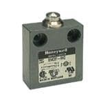
ICGOO电子元器件商城为您提供14CE1-3由Honeywell Solid State Electronics设计生产,在icgoo商城现货销售,并且可以通过原厂、代理商等渠道进行代购。 提供14CE1-3价格参考¥609.78-¥829.67以及Honeywell Solid State Electronics14CE1-3封装/规格参数等产品信息。 你可以下载14CE1-3参考资料、Datasheet数据手册功能说明书, 资料中有14CE1-3详细功能的应用电路图电压和使用方法及教程。
| 参数 | 数值 |
| IP等级 | IP 65 |
| 品牌 | Honeywell |
| 产品目录 | 机电产品 |
| 描述 | 限位开关 Enclosed BasicSwitch |
| 产品分类 | 工业自动化 |
| 产品手册 | http://sensing.honeywell.com/index.php?ci_id=149558 |
| 产品图片 |
|
| rohs | 符合RoHS |
| 产品系列 | 开关,限位开关,Honeywell 14CE1-3 |
| mouser_ship_limit | 该产品可能需要其他文件才能进口到中国。 |
| NEMA额定值 | 1, 3 |
| 产品型号 | 14CE1-3 |
| 产品种类 | |
| 商标 | Honeywell |
| 工作力 | 0.99 lb |
| 开关类型 | Limit Switches |
| 执行器 | Plunger |
| 电压额定值AC | 240 V |
| 电压额定值DC | - |
| 电流额定值 | 5 A |
| 端接类型 | Screw |
| 触点形式 | SPDT |


_renders/IS43R16800E-5TL.jpg)

- 商务部:美国ITC正式对集成电路等产品启动337调查
- 曝三星4nm工艺存在良率问题 高通将骁龙8 Gen1或转产台积电
- 太阳诱电将投资9.5亿元在常州建新厂生产MLCC 预计2023年完工
- 英特尔发布欧洲新工厂建设计划 深化IDM 2.0 战略
- 台积电先进制程称霸业界 有大客户加持明年业绩稳了
- 达到5530亿美元!SIA预计今年全球半导体销售额将创下新高
- 英特尔拟将自动驾驶子公司Mobileye上市 估值或超500亿美元
- 三星加码芯片和SET,合并消费电子和移动部门,撤换高东真等 CEO
- 三星电子宣布重大人事变动 还合并消费电子和移动部门
- 海关总署:前11个月进口集成电路产品价值2.52万亿元 增长14.8%
_renders/IS42S32800D-6BLI.jpg)


PDF Datasheet 数据手册内容提取
MICRO SWITCH™ Compact Precision Limit Switches 14CE Series Datasheet
MICRO SWITCH™ 14CE Series Compact Precision Limit Switches All MICRO SWITCH™ 14CE Series compact enclosed switches incorporate fluorocarbon diaphragm sealing to provide reliable protection, meeting IP65, IP66, IP67, and IP68, as well as NEMA 1, 2, 3, 3R, 4, 6, 6P, and 13 require- ments. Versions with a boot seal also meet NEMA 12 requirements (dust, falling dirt, liquid media with solid contami- nates). The cable or connector and basic switch terminals are encapsulated in an epoxy sealant, offering excellent resistance in harsh environments. For low temperature applications (down to -40 °C, -40 °F), CE Series switches can be supplied with low temperature seals and lubricant. The CE Series switches are rugged and versatile switches which can be applied indoors in many harsh factory floor applications, as well as on outdoor equipment in extreme temperatures. A full range of actuators are available, includ- ing plain plungers, roller plungers, side rotary, multi-directional wire, and manually operated. The switches are also available with the industry standard, M12 micro-change 4-pin connector. MICRO SWITCH™ 14CE products meet worldwide CE requirements. What makes our switches better? Compact construction for minimal real estate on equipment Gang mounting capability to provide a multi-plunger limit switch Rugged, die-cast zinc housing for demanding environments Variety of cable length options and choice of side or bottom exit cable/connector for design flexibility Functionality over a wide temperature range with factory sealed connectors or wiring Big performance in a little package. CUSTOMIZATION • COMPACT HIGH PERFORMING • DURABILITY 2 sensing.honeywell.com
FFeeaattuurreess RUGGED, COMPACT CONSTRUCTION aanndd BBeenneefifittss MICRO SWITCH™ 14CE Series limit switches’ compact construction requires minimal real estate on equipment. Consistent performance is delivered in many demanding environments where petroleum, synthetic or water based fluids are present. Its die-cast zinc housing and fluorocarbon diaphragm seal maintain a tightly sealed, IP65/66/67/68 and NEMA 1, 2, 3, 3R, 4, 6, 6P, 12 (boot seal), 13 rugged package. Gang-mounting option CUSTOMIZATION Switches are pre-leaded (harmonized CENELEC cable) or supplied with a M12 four-pin connector to decrease installation time. 14CE Series’ wide selection of actuators minimize installation or time issues. Cable length variations are available for equipment requiring different cable lengths with side and bottom exit cable/connector options for equipment flexibility. COMPACT DESIGN Rugged, compact switch designed with the common 25 mm mounting centers. The 14CE Series is engineered with MICRO SWITCH™ SM switches for consistent, precise actuation. High performance switch for small spaces LONG LIFE Mechanical life up to five million cycles for wobble actuators, and up to ten million cycles for all other actuators delivers long-lasting performance. DESIGN FLEXIBILITY Gang mounting capability provides a multi-plunger limit switch option. Low temperature variants are available for indoor and outdoor applications. GLOBAL APPLICATIONS MICRO SWITCH™ 14CE limit switches have CE approval for world-wide use. sensing.honeywell.com 3
Potential Applications MACHINE TOOLS Detects tool and piece part location on CNC and other machining equipment OFF-ROAD EQUIPMENT Used as a cab door switch on crane booms MATERIAL HANDLING Used in forklifts and dock locks for trucks and trailers, and vehicle wash systems ACCESS AND MOBILITY SOLUTIONS Often used on vehicle wheelchair lifts and stairway lifts TEXTILE MACHINERY Senses roll size, tensioning, and other functions ROBOTICS Controls arm movement limits PACKAGING EQUIPMENT Often used on stretch pallet wrapping equipment PRINT TRADE MACHINERY Senses roll size, tensioning, along with controlling gates and panels AGRICULTURAL MACHINERY Used on grain and livestock equipment 4 sensing.honeywell.com
MICRO SWITCH™ Compact Precision Limit Switches Table 1. Specifications Characteristic Parameter Description compact enclosed limit switch • Top pin plunger (14CE1-) • Parallel roller plunger (14CE2-) • Cross roller plunger (14CE3-) • Front rotary (14CE16-) • Top pin plunger with boot seal (14CE18-) • Top adjustable plunger (14CE19-) • Wobble (14CE20-) • Manually operated (14CE22-) Actuators • Top pin plunger, panel mount (14CE27-) • Ball bearing plunger (14CE66-) • Top roller plunger, parallel and panel mount (14CE28-) • Top roller plunger, perpendicular, panel mount (14CE29-) • Top roller plunger, parallel and boot sealed (14CE31-) • Top roller plunger, perpendicular, boot seal (14CE55-) Harmonized CENELEC PVC sheathed 4 x 0,75 mm2 (18 AWG) cable Terminations Connector (dc), 4-pin male, M12 thread (-Q) Connector (ac), 4-pin male, 1/2 in x 20 thread (-Q1) Switching options SPDT, snap action contacts (1NC/1NO) IP65, IP66, IP67, IP68 Sealing NEMA 1, 2, 3, 3R, 4, 6, 6P, 12 (boot seal), 13 Operating temperature 0 °C to 70 °C [32 °F to 158 °F]; optional -40 °C to 70 °C [-40 °F to 158 °F] up to 10 million Mechanical life up to 5 million (wobble actuators) Thermal current 1 A, 3 A, 5 A (depending upon model) Rated insulation voltage (Ui) 250 V Rated impulse withstand volt- 1.5 kV age (Uimp) Pollution degree 3 Min. actuation speed 0.003 m/s Max. actuation speed 0.1 m/s Max. actuation frequency ac – 200 Hz; dc – 20 Hz Shock 50 g – IEC68-2-27 Vibration 10 G – IEC68-2-6 Approvals CE Conforming to standards IEC947-5-1, EN 60947-5-1; AC14 D300, DC13 R300 Table 2. Electrical Ratings (in amperes) Model example Contacts Rating 14CE_-_ Silver contacts A 14CE_-_G Gold contacts B 14CE_-Q, -AQ, -AQ1 Silver contacts C with 4-pin connector Rating code Electrical Rating Make Break 240 Vac, ind. 1.2 0.2 240 Vac, res. 5 5 A 28 Vdc, res. 3 3 28 Vdc, ind. 3 3 5 A, 1/10 HP, 125 Vac or 250 Vac – – 1 A res., 0.5 A ind., 30 Vdc B – – 1 A, 125 Vac C 3 A, 125 Vac or 250 Vac – – sensing.honeywell.com 5
14CE Series SWITCHING AND LEAD IDENTIFICATION 14CE SPDT GREEN/YELLOW BROWN 2 GREY 1 = Common 1 2 = Normally Closed 3 3 = Normally Open BLACK NC 2 PINOUTS NO3 1C Connector - (dc) (-Q) Connector (ac) (-Q1) NO3 1C NC 2 NO3 1C NC2 NO3 1C CONNECTOR VERSIONS MOUNTING The 14CE SNCer2ies is available with a 4-pin, M12 size connector in MICRO SWITCH™ 14CE Series switches are mounted by using both bottom and side exit versions. two M5 screws. The mounting holes are counter bored to keep -Q Version -Q1 Version the screw heads within the overall switch housing dimensions. GANG MOUNT CAPABILITY 8.0 The housing on the 14CE Series has been designed to enable 15 5 the user to build his own multiple plunger switch by gang mount- 1 dcB tryadp eH a4r rpisionn mcoanl,enector M1C2AT t. hNroe.8a0d466 M12 Thread ac type, 4 pin male, ing several switches. All pin plunger and roller plunger types are 1/2 in x 20 thread suitable for gang mounting. There is a 16 mm distance between the plungers. Both Series are very versatile that even a lever-type OPTION Q OPTION Q1 version could be added at the end of the row. BOTTOM EXIT OR SIDE EXIT ORIENTATION The CE Series has been designed with a pre-wired cable or con- nector fitted in the bottom of the switch housing. Other variations are available with a side-exit cable or connector. GOLD CONTACT VERSIONS For low energy applications (up to 30 Vdc, 1 A), gold contact ver- sions of the 14CE switches can be supplied upon request. 6 sensing.honeywell.com
MICRO SWITCH™ Compact Precision Limit Switches GENERAL DIMENSIONS • ALL SWITCHES CABLE VERSION Option B. Elongated mounting holes 40 mm max. 16 mm max. Two slots Ø 5,1 mm [0.20 in] [1.57 in max.] [0.63 in max.] c/bore Ø 10,2 mm [0.40 in] 4,8 mm ref. x 6 deep [0.19 in] 25 mm 5,0 mm ref. [0.98 in] [0.20 in] Two (2) holes Ø 5.1 mm [Ø 0.2 in] dia., c/bore 10,2 mm dia x 6 mm deep [0.40 in dia x 0.24 in deep] Pretravel (PT) (Both sides - option “A” only) Overtravel (OT) Max. free length 3 mm min. [0.12 in min.] 8,0 mm poOsiptioenra (tOinPg) [70,.63 0m imn] 44 mm max. [0.32 in] Mth1re2ad 1th/2re xa d20 UNF [1.73 in max.] MICRO SWITCH™ 914CE Miniature Limit Switch Product Nomenclature 8,0 mm TYPE TYPE [0.31 in] Q OE Q1 15,0 mm [0.59 in] 15,0 mm [0.59 in] PRODUCT NOMENCLATURE 14CE 16 – 3 Connectors Switch Type Actuator Type Cable Length Options1,2 (micro type) 14CE Series dc type Compact 1 Tpolupn pgienr 22 Mnyalonnu ablluyt toopner. 1 1 meter A Side entry Q s4i-npginle m kaelyew, aMy12 Precision ac type 2 Top roller 27 Top pin plunger 2 2 meters B Elongated Q1 two keyways Limit Switch plunger, parallel panel mount mounting holes 4-pin male, 1/2-20 3 Tpolupn rgoellre, rperp. 28 Tppolaupnn ergol elmlre,o rp uanrtallel 3 3 meters D Hcaablolegen-free 16 Front 29 Tpolupn rgoellre, rperp. 4 4 meters G Gold rotary panel mount contacts 18 Top pin plunger 31 Tpolupn rgoellre, rp arallel 5 5 meters H High temp., w/ boot seal boot seal 150 °C 19 Top adjustable 55 Tpolupn rgoellre, rperp. L L-4o0w ° tCe mswpi.t,ch pin plunger boot seal and cable 20 Coil 66 Top ball bearing L1 L-4o0w ° tCe,m cpa.ble wobble plunger not for flexing Top P NOTE: not all combinations of model code are available. mounting Please contact your Honeywell provider/representative for assistance. Vitron seals/ V gasket 1More than one option may be permissible. (front rotary and booted sealed 2OPTION K to be discontinued. Replaced with fluorocarbon diaphragm seal, standard switch. plungers only) 2OPTION KV to be discontinued. Replaced with fluorocarbon diaphragm seal, standard switch. Bottom exit is standard. sensing.honeywell.com 7
14CE Series PRODUCT SPECIFICATIONS AND LISTINGS Contact your Honeywell rep or distributor for additional listings 14CE1 • Pin Plunger Con- Elec Cable Free Operating Options Listing 14CE27 • Pin Plunger Panel Mount tacts Rating1 Exit Position Position (FP) (OP) Ø10,0 mm 17,5 mm 15,7 mm [Ø0.39 in] 17,5 15,7 12,7 Silver A Bottom – 14CE1-1 OT PT FP GRY-BRN (cid:31) [0.69 in] [0.62 in] GRY-BLK 17,5 mm 15,7 mm Gold-plated OP GRY-BLK (cid:30) Gold B Bottom 14CE1-1G GRY-BRN [0.69 in] [0.62 in] contacts 15,8 17,5 mm 15,7 mm Pretravel • 1,8 mm [0.071 in] Silver A Side Side exit cable 14CE1-1A M10 X 1 ME1T2R mICm T [H0.R4E9A inD] Diff. travel • 0,1 mm [0.004 in] [0.69 in] [0.62 in] THREADED LENGTH OT Overtravel • 3,0 mm [0.118 in] 17,5 mm 15,7 mm dc-type Silver C Bottom 14CE1-Q Oper. force • 11,8 N [2.65 lb] [0.69 in] [0.62 in] connector PT 31,1 mm 29,3 mm OP FP 31,1 29,3 26,3 Silver A Bottom Panel mount 14CE27-1 GRY-BRN (cid:31) [1.23 in] [1.15 in] GRY-BLK GRY-BLK (cid:30) GRY-BRN 29,4 14CE18 • Boot Sealed Pin Plunger Con- Elec Cable Free Operating Options Listing tacts Rating1 Exit Position Position (FP) (OP) 26,7 mm 24,9 mm 26,7 24,9 21,9 Silver A Bottom – 14CE18-1 GRY-BRN (cid:31) [1.05] [0.98 in] Ø7,0 mm BOOT SEAL GRY-BLK [Ø0.28 in] PT 26,7 mm 24,9 mm OT GRY-BLK (cid:30) Silver A Side Side exit cable 14CE18-1A GRY-BRN [1.05] [0.98 in] 25 OP FP Pretravel • 1,8 mm [0.071 in] Silver C Bottom 26,7 mm 24,9 mm dc-type 14CE18-Q [1.05] [0.98 in] connector Diff. travel • 0,1 mm [0.004 in] Overtravel • 3,0 mm [0.118 in] Oper. force • 22,5 N [5.06 lb] 14CE66 • Ball Bearing Plunger Con- Elec Cable Free Operating Options Listing tacts Rating1 Exit Position Position (FP) (OP) 26,2 24,4 21,4 26,2 mm 24,4 mm 7,9 mm [0.31 in] DIA GRY-BRN (cid:31) Silver A Bottom [1.03 in] [0.96 in] – 14CE66-1 BALL BEARING GRY-BLK OT PT GRY-BLK (cid:30) GRY-BRN 26,2 mm 24,4 mm Silver A Side Side exit cable 14CE66-1A 24,5 [1.03 in] [0.96 in] OP FP Pretravel • 1,8 mm [0.071 in] Diff. travel • 0,1 mm [0.004 in] Overtravel • 3,0 mm [0.118 in] Oper. force • 11,8 N [2.65 lb] 1 Page 5 for electrical codes Note: Most part numbers are shown with 1 meter of cable. The -X indicates the number of meters of cable provided: 2-meters, 3-meters, 4-meters, and 5-meters. Custom lengths are also available. 8 sensing.honeywell.com
MICRO SWITCH™ Compact Precision Limit Switches 14CE2 • Roller Plunger Con- Elec Cable Free Operating Options Listing 14CE28 • Roller Plunger Panel Mount tacts Rating1 Exit Position Position (FP) (OP) Ø12,4 mm 30,3 mm 28,5 mm [Ø0.49 in] PT Silver A Bottom – 14CE2-1 [1.19 in] [1.12 in] 30,3 28,5 25,5 GRY-BRN (cid:31) Gold B Bottom 30,3 mm 28,5 mm Gold-plated 14CE2-1G OT GRY-BLK [1.19 in] [1.12 in] contacts OP FP GRY-BLK (cid:30) GRY-BRN 30,3 mm 28,5 mm dc-type 28,6 Silver C Bottom 14CE2-Q [1.19 in] [1.12 in] connector Pretravel • 1,8 mm [0.071 in] 30,3 mm 28,5 mm ROLLER Diff. travel • 0,1 mm [0.004 in] Silver A Side Side exit cable 14CE2-1A Ø 12,4 mm x 4,7 mm [1.19 in] [1.12 in] [Ø 0.48 in x 0.020 in] Overtravel • 3,0 mm [0.118 in] M14 X 1 THREAD 44,3 mm 42,5 mm Panel mount, OT Oper. force • 11,8 N [2.65 lb] Silver A Bottom 14CE28-2 [1.75 in] [1.67 in] 2 m cable 44,3 42,5 39,5 PT GRY-BRN (cid:31) OP FP GRY-BLK GRY-BLK (cid:30) GRY-BRN 42,6 14CE31 • Boot Sealed Roller Plunger Con- Elec Cable Free Operating Options Listing tacts Rating1 Exit Position Position (FP) (OP) ROLLER 36,2 mm 34,4 mm Ø 12,4 mm x 4,7 mm 36,2 34,4 31,4 Silver A Bottom – 14CE31-1 Ø 0.48 in x 0.020 in] GRY-BRN (cid:31) [1.43 in] [1.36 in] BOOT SEAL PT GRY-BLK OT 36,2 mm 34,4 mm Fluorocarbon GRY-BLK (cid:30) Silver A Bottom 14CE31-6V GRY-BRN [1.43 in] [1.36 in] seals, 6 m cable 34,5 OP FP Pretravel • 1,8 mm [0.071 in] Diff. travel • 0,1 mm [0.004 in] Overtravel • 3,0 mm [0.118 in] Oper. force • 17,5 N [3.93 lb] 14CE3 • Cross Roller Plunger Con- Elec Cable Free Operating Options Listing tacts Rating1 Exit Position Position (FP) (OP) Ø[Ø102.,449 m inm] GRY-BRN30,3 28,5 25,5(cid:31) Silver A Bottom 3[10.,139 m inm] 2[18.,152 m inm] – 14CE3-1 OT PT GRY-BLK GRY-BLK (cid:30) 30,3 mm 28,5 mm 3 m of cable, Silver A Side 14CE3-3A GRY-BRN [1.19 in] [1.12 in] side exit 28,6 OP FP Pretravel • 1,8 mm [0.071 in] Silver C Bottom 30,3 mm 28,5 mm dc-type 14CE3-Q Diff. travel • 0,1 mm [0.004 in] [1.19 in] [1.12 in] connector Overtravel • 3,0 mm [0.118 in] Oper. force • 11,8 N [2.65 lb] 1 Page 5 for electrical codes Note: Most part numbers are shown with 1 meter of cable. The -X indicates the number of meters of cable provided: 2-meters, 3-meters, 4-meters, and 5-meters. Custom lengths are also available. sensing.honeywell.com 9
14CE Series 14CE55 • Boot Sealed Cross Roller Con- Elec Cable Free Operating Options Listing Plunger tacts Rating1 Exit Position Position (FP) (OP) 36,2 34,4 31,4 36,2 mm 34,4 mm ROLLER Silver A Bottom 3 meters of cable 14CE55-3 Ø 12,4 mm x 4,7 mm GRY-BRN (cid:31) [1.43 in] [1.36 in] Ø 0.48 in x 0.020 in] GRY-BLK OT BOOT SEAL PT GRY-BLK (cid:30) GRY-BRN 34,5 Pretravel • 1,8 mm [0.071 in] OP FP Diff. travel • 0,1 mm [0.004 in] Overtravel • 3,0 mm [0.118 in] Oper. force • 17,5 N [3.93 lb] 14CE16 • Side Rotary Con- Elec Cable Free Operating Options Listing tacts Rating1 Exit Position Position (FP) (OP) Silver A Bottom – – 14CE16-12 0° 30° 70° FP GRY-BRN (cid:31) Gold-plated PT PT GRY-BLK GRY-BLK (cid:30) Gold B Bottom – – contacts, 14CE16-3G2 OT OT GRY-BRN 3 meters of cable DT DT 27° dc-type Pretravel • 30° Silver C Bottom – – 14CE16-Q2 ActuØa7to,3r2 s hmamft 1[08.,794 m inm] Diff. travel • 3° connector [Ø0.288 in] Overtravel • 40° Oper. force • 0,34 Nm [3 in-lb] 14CE20 • Random Motion Con- Elec Cable Free Operating Options Listing Wire Actuator Wobble tacts Rating1 Exit Position Position (FP) (OP) 28 mm OP ALL DIRECTIONS EXCEPT DIRECT Silver A Bottom – [1.10 in] – 14CE20-1 PULL max. 0 28 max. GRY-BRN [ØØ10..80 7m imn] GRY-BLK GRY-BLK GRY-BRN 335,0 mm max. [13,98 mm max.] Oper. position • 28 mm [1.10 in] max. Oper. force • 0,55 N [0.12 lb] max. 1 Page 5 for electrical codes 2 Switch operates on clockwise and counterclockwise rotation of lever shaft Note: Most part numbers are shown with 1 meter of cable. The -X indicates the number of meters of cable provided: 2-meters, 3-meters, 4-meters, and 5-meters. Custom lengths are also available. 10 sensing.honeywell.com
ADDITIONAL INFORMATION WARNING The following associated literature is available on the Honeywell Web PERSONAL INJURY site at sensing.honeywell.com: DO NOT USE these products as safety or emergency stop • Product installation instructions devices or in any other application where failure of the • Product range guide product could result in personal injury. • Product nomenclature tree Failure to comply with these instructions could result in • Product application-specific information death or serious injury. – Limit and enclosed switches application information – Limit and enclosed switches operating characteristics WARNING – Limit and enclosed switches reference standards MISUSE OF DOCUMENTATION – Limit and enclosed switches typical applications • The information presented in this product sheet is for – Product flyer: CE Family Miniature Limit Switches reference only. Do not use this document as a product installation guide. • Complete installation, operation, and maintenance information is provided in the instructions supplied with each product. Failure to comply with these instructions could result in death or serious injury. WARRANTY/REMEDY Honeywell warrants goods of its manufacture as being free of defective materials and faulty workmanship. Honeywell’s standard product warranty applies unless agreed to otherwise by Honeywell in writing; please refer to your order acknowledgement or consult your local sales office for specific warranty details. If warranted goods are returned to Honeywell during the period of coverage, Honeywell will repair or replace, at its option, without charge those items it finds defective. The foregoing is buyer’s sole remedy and is in lieu of all other warranties, expressed or implied, including those of merchantability and fitness for a particu- Find out more lar purpose. In no event shall Honeywell be liable for conse- Honeywell serves its customers quential, special, or indirect damages. through a worldwide network of sales offices, representatives While we provide application assistance personally, through our and distributors. For application literature and the Honeywell website, it is up to the customer to assistance, current specifications, determine the suitability of the product in the application. pricing or name of the nearest Authorized Distributor, contact Specifications may change without notice. The information we your local sales office. supply is believed to be accurate and reliable as of this printing. However, we assume no responsibility for its use. To learn more about Honeywell’s sensing and switching products, call +1-815-235-6847 or 1-800-537-6945, visit sensing.honeywell.com, or e-mail inquiries to info.sc@honeywell.com Sensing and Productivity Solutions Honeywell 1985 Douglas Drive North Golden Valley, MN 55422 002387-3-EN IL50 GLO September 2015 honeywell.com Copyright © 2015 Honeywell International Inc. All rights reserved.
Mouser Electronics Authorized Distributor Click to View Pricing, Inventory, Delivery & Lifecycle Information: H oneywell: 14CE1-2 14CE1-2G 14CE1-2GL 14CE1-2K 14CE1-2L 14CE1-3 14CE1-3A 14CE1-3AH 14CE1-3AK 14CE1- 3AKV 14CE1-3G 14CE1-3GK 14CE1-3K 14CE1-4 14CE1-4K 14CE1-5 14CE1-6 14CE1-6KV 14CE1-7 14CE18- 1 14CE18-15A 14CE18-1A 14CE18-1L 14CE18-3 14CE18-6 14CE18-6A 14CE1-9A 14CE1-AQ 14CE1-Q 14CE20-1 14CE20-3 14CE20-6 14CE2-1 14CE2-10 14CE2-1A 14CE2-1G 14CE2-1K 14CE2-1L 14CE2-1L1 14CE2-2 14CE2-2A 14CE2-2K 14CE2-2KV 14CE2-3 14CE2-3A 14CE2-3D 14CE2-3G 14CE2-3K 14CE2-3KV 14CE2-4 14CE2-5 14CE2-6 14CE2-6KV 14CE27-1 14CE2-7A 14CE28-2 14CE29-1 14CE2-AQ 14CE2-Q 14CE3-1 14CE31-2AL 14CE31-2L 14CE31-3 14CE31-4A 14CE31-6 14CE3-1K 14CE3-1L1 14CE3-2 14CE3-2AG 14CE3-3 14CE3-3A 14CE3-3AH 14CE3-3K 14CE3-3KV 14CE3-4AG 14CE3-6 14CE3-AQ 14CE3-Q 14CE55-3 14CE66-1 14CE66-1A 14CE66-2 14CE66-4A 14CE101-1 14CE101-10 14CE101-2 14CE101-3 14CE101-4 14CE101-6 14CE102-1 14CE102-12 14CE102-15 14CE102-3 14CE102-3G 14CE102-5 14CE102-6 14CE102-6G 14CE102-8 14CE103-1 14CE103-3