ICGOO在线商城 > 1454G2

 Datasheet下载
- 型号: 1454G2
- 制造商: ANDERSON POWER PRODUCTS
- 库位|库存: xxxx|xxxx
- 要求:
| 数量阶梯 | 香港交货 | 国内含税 |
| +xxxx | $xxxx | ¥xxxx |
查看当月历史价格
查看今年历史价格
1454G2产品简介:
ICGOO电子元器件商城为您提供1454G2由ANDERSON POWER PRODUCTS设计生产,在icgoo商城现货销售,并且可以通过原厂、代理商等渠道进行代购。 提供1454G2价格参考以及ANDERSON POWER PRODUCTS1454G2封装/规格参数等产品信息。 你可以下载1454G2参考资料、Datasheet数据手册功能说明书, 资料中有1454G2详细功能的应用电路图电压和使用方法及教程。
| 参数 | 数值 |
| 品牌 | Anderson Power Products |
| 产品目录 | |
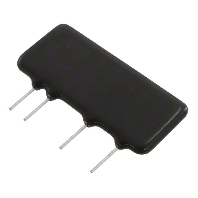
| 描述 | 重负荷电源连接器 PP PAK-8P PLUG NO LATCH |
| 产品分类 | 电源连接器 |
| 产品手册 | |
| 产品图片 |
|
| rohs | 符合RoHS |
| 产品系列 | 重负荷电源连接器,Anderson Power Products 1454G2 |
| 产品型号 | 1454G2 |
| 产品种类 | 重负荷电源连接器 |
| 产品类型 | Housings |
| 位置数量 | 8 |
| 商标 | Anderson Power Products |
| 商标名 | Powerpole |
| 外壳材料 | Polycarbonate (PC) |
| 工厂包装数量 | 50 |
| 插入/联系人性别 | Male |
| 电压额定值 | 600 V |
| 电流额定值 | 40 A |
| 系列 | PP30 |
| 线规量程 | 16-12 |
| 触点材料 | Copper Alloy |


- 商务部:美国ITC正式对集成电路等产品启动337调查
- 曝三星4nm工艺存在良率问题 高通将骁龙8 Gen1或转产台积电
- 太阳诱电将投资9.5亿元在常州建新厂生产MLCC 预计2023年完工
- 英特尔发布欧洲新工厂建设计划 深化IDM 2.0 战略
- 台积电先进制程称霸业界 有大客户加持明年业绩稳了
- 达到5530亿美元!SIA预计今年全球半导体销售额将创下新高
- 英特尔拟将自动驾驶子公司Mobileye上市 估值或超500亿美元
- 三星加码芯片和SET,合并消费电子和移动部门,撤换高东真等 CEO
- 三星电子宣布重大人事变动 还合并消费电子和移动部门
- 海关总署:前11个月进口集成电路产品价值2.52万亿元 增长14.8%


PDF Datasheet 数据手册内容提取
Powerpole® Connectors - PP15 to PP45 : PP15-45 series are the smallest Powerpole® housings. They can be used for wire-to-wire or wire-to-board applications. Wire sizes up to 55 Amps from #20 AWG (0.75 mm²) to #10 (6 mm²) offer power capabilities up to 55 amps per pole. Finger proof housings and the ability to incorporate first-mate last-break ground connectors enhance the capabilities of this Powerpole® series. High Power Density • Up to 55 amps in a compact footprint Wire-to Wire & Wire-to-Board Configurations • Wire & PCB contacts can be used in the same housings 5 Finger Proof Housings Available 4 o • Protects against accidental contact with live circuits t 5 1 P 2P N ®e Ool Ip Tr Cwe | PP15-45 ORDERING INFORMATION | E o SP PP15-45 Finger Proof Housings PP15-45 Finger Proof & Standard & Ground Improved on the original APP design by adding ribs to mating interface to Housing Dimensions protect against accidental contact with live circuits. Meets the requirements of UL1977 section 10.2 and is rated IP20. Will not mate with standard housings. [ 7.9 ] Front View Description ------------ Part Numbers ------------ 0.31 [ 2 4 . 6 ] Mated Length Minimum Quantity ... 2,500 200 ..... F inger Proof 0.97 Rib Feature Red 1327FP-BK 1327FP [ 7.9 ] [ 8.4 ] Green 1327G5FP-BK 1327G5FP 0.31 0.33 Black 1327G6FP-BK 1327G6FP White 1327G7FP-BK 1327G7FP [ 41.2 ] Blue 1327G8FP-BK 1327G8FP 1.62 Yellow 1327G16FP-BK 1327G16FP PP15-45 Standard Housings This original housing design has an open interface and is available in a wide array of colors. Will not mate with finger proof housings. Description ------- Part Numbers ------ Minimum Quantity ... 2,500 200 ... Red 1327-BK 1327 Green 1327G5-BK 1327G5 Black 1327G6-BK 1327G6 White 1327G7-BK 1327G7 Blue 1327G8-BK 1327G8 Yellow 1327G16-BK 1327G16 Orange 1327G17-BK 1327G17 Gray 1327G18-BK 1327G18 Brown 1327G21-BK 1327G21 Pink 1327G22-BK 1327G22 Purple 1327G23-BK 1327G23 45A Premate Ground Housings - (for use with ground contacts only) Green housings are keyed to prevent accidental mating with standard or finger proof Powerpole® housings. Description ------ Part Numbers ----- Minimum Quantity ... 2,500 200 ... Green 1827G1-BK 1827G1 © 2018 Anderson Power Products, Inc. All rights reserved. APP®, Anderson Power Products®, A®, Powerpole®, SPEC Pak® and the APP Logo are registered trademarks of Anderson Power Products, Inc. - 20 - www.andersonpower.com All Data Subject To Change Without Notice
PP15-45 Tin Plated Power Contacts Offer cost effective performance up to 1,500 mating cycles. See specifications and temperature Open Barrel Contact charts for amperage ratings by wire size. Dimensions [ 3.6 ] [ 3.6 ] Mating Loose Piece Reeled - A - 0.14 0.14 Barrel AWG mm² Force -------- Part Numbers ------- inches mm Minimum Quantity ....................................... 200 5,000 ......................... [ 17.2 ] Open 14 to 10 K* 2.1 to 5.3 High 269G3-LPBK 269G3 0.21 5.33 [ 6.4 ] 0.68 Open 14 to 10 K* 2.1 to 5.3 Low 261G2-LPBK 261G2 0.20 5.08 0.25 Open 14 to 10 SF* 2.1 to 6.0 High 201G1H-LPBK 201G1H 0.24 6.10 A Open 14 to 10 SF* 2.1 to 6.0 Low 200G1L-LPBK 200G1L 0.24 6.10 Open 16 to 12 1.3 to 3.3 High 269G1-LPBK 269G1 0.18 4.57 Open 16 to 12 1.3 to 3.3 Low 261G1-LPBK 261G1 0.18 4.57 Open 20 to 16 0.52 to 1.3 High 269G2-LPBK 269G2 0.16 4.06 Open 20 to 16 0.52 to 1.3 Low 262G1-LPBK 262G1 0.16 4.06 K* - For #10 AWG class K stranded wire or smaller. For larger wires use superflex contacts. SF*- Indicates wires with high stranding such as Super Flex. PS oE w PP15-45 Silver Plated Power Contacts C Open Barrel Contact e Maximize performance by offering up to 10,000 mating cycles and are recommended for circuit interrupt or rT hot plug applications. See specifications and temperature charts for amperage ratings by wire size. Only close d [ 17.27 ] poIO b arrel contac t s a r e suitable for soldering. 0.68 [ 6.35 ] leN Dimensions 0.25 P® 2 Mating Loose Piece Reeled - A - - B - [ 3.81 ] P A 1 Barrel AWG mm² Force ------- Part Numbers -------- Part Numbers inches mm inches mm 0.15 5 Minimum Quantity .......................................... 5,000 200 5,000 ................................................. to Open 14 to 10 K* 2.1 to 5.3 Low - 261G3-LPBK 261G3 0.20 5.08 - - 4 Open 14 to 10 SF* 2.1 to 6.0 Low - 200G3L-LPBK 200G3L 0.24 6.10 - - 5 Closed Barrel Contact Open 20 to 16 0.52 to 1.3 Low - 262G2-LPBK 262G2 0.16 4.06 - - Closed 16 to 12 1.3 to 3.3 Low 1331-BK 1331 - 0.15 3.81 0.10 2.54 [ 16.26 ] [ 7.35 ] Closed 20 to 16 0.52 to 1.3 Low 1332-BK 1332 - 0.12 3.05 0.07 1.78 0.64 0.29 K* - For #10 AWG class K stranded wire or smaller. For larger wires use superflex contacts. B [ 3.81 ] A SF*- Indicates wires with high stranding such as Super Flex. 0.15 45A Premate Ground Wire Contacts - (for use with ground housing only) Tin or silver plated contacts are rated for ground or power. Hand tools are available for loose piece Open Barrel Premate Contact contacts. Reeled contacts can be used with high volume press and applicator tooling. Tin contacts are rated for up to 1,500 mating cycles. Silver contacts are rated up to 10,000 mating cycles. [ 3.6 ] [ 19.1 ] 0.14 0.75 Reeled [ 6.4 ] Mating Loose Piece Part 0.25 Type AWG mm² Force - Part Numbers - - Numbers - Minimum Quantity ............................................. 200 5,000 ..... [ 6.1 ] 0.24 Open, Tin 14 to 10 2.1 to 6.0 Low 1830G1-LPBK 1830G1 Open, Silver 14 to 10 2.1 to 6.0 Low 1830G2-LPBK 1830G2 [ 6.1 ] 0.24 25A Right Angle PCB Contacts Tin Plated Suitable for right angle applications up to 25A per pole. Tin plating enhances solderability. Cannot be mixed with 45A PCB contacts. For mating with wire contacts only. Dimensions Mating Loose Piece - A - - B - Row Force ------- Part Numbers ------- inches mm inches mm Minimum Quantity ... 1,000 100 ................................................... A [ 9.9 ] Top Low 1377G1-BK 1377G1 0.59 14.80 1.52 38.60 0.39 High 1317G1-BK 1317G1 Bottom Low 1377G2-BK 1377G2 0.29 7.20 1.36 34.50 B High 1317G2-BK 1317G2 Top Low 1377G11-BK 1377G11 0.59 14.80 1.21 30.70 Use mounting staples with right angle contacts High 1317G11-BK 1317G11 (see accessories). Bottom Low 1377G12-BK 1377G12 0.29 7.20 1.01 25.70 High 1317G12-BK 1317G12 See website for PCB layout drawing. 25A Vertical PCB Contacts Tin Plated For mating with wire contacts only. Suitable for vertical applications up to 25A per pole, tin plating enhances solderability. Dimensions Mating Loose Piece - A - Force ---------------- Part Numbers --------------- inches mm Minimum Quantity .... 1,000 100 ....................... Low 1377G3-BK 1377G3 2.22 56.40 [ 3.1 ] High 1317G3-BK 1317G3 2.22 56.40 0.12 A Low 1377G4-BK 1377G4 1.76 44.70 Housing end High 1317G4-BK 1317G4 1.76 44.70 Low 1377G13-BK 1377G13 1.17 29.70 High 1317G13-BK 1317G13 1.17 29.70 - 21 - All Data Subject To Change Without Notice www.andersonpower.com
45A Right Angle and Vertical PCB Contacts Tin Plated Vertical [ 36.5 ] Suitable for right angle or vertical applications up to 45A per pole. Tin plating 1.44 enhances solderability. Right angle contacts cannot be mixed with 25A PCB [ 28.6 ] c ontacts. For mating with wire c o n t a c t s L oonolsy.e Piece [ R219.E1.F77 ] [ 05..210 ] [ 05..283 ] 1.13 [ 106.6.34 ] Description ----------- Part Numbers ----------- [ 7.9 ] [ 7.9 ] PP15/45 Housings Minimum Quantity ............. 1,000 100 .................... 0.31 0.31 (1327 Series) Vertical 3-5911P1 1335G1 TYP TYP Right Angle Contact Right Angle Bottom Row 3-5912P1 1336G1 Horizontal (bottom) Right Angle Top Row 3-5913P1 1337G1 Use mounting staples with right angle Cat.No. 1336G1 contacts (see accessories). Right Angle Contact Horizontal (top), Cat.No. 1337G1 45A Premate Ground PCB Contacts Right angle contacts are suitable for power or ground. Use to mate with 45A [ 45.3 ] [ 7.9 ] ground wire contacts. Tin plated contacts are rated up to 1,500 mating cycles. 1.78 [ 41.2 ] 0.31 TYP [ 14.7 ] Can be used with other 45A PCB connectors in the bottom row. 1.62 [ 8.4 ] 0.578 0.33 TYP Mating Loose Piece Force ------- Part Numbers ------- [ 5.6 ] Pre-mate wire 5 [ 3.6 ] 0.22 [ 7.9 ]connector to 4 MPCinBim, Bumot tQomua Rntoitwy . . . . . . .L..o..w.. ...... 3 - 15090502 P 1 1 8 13060G 1 .... 0.14 [ 218.1.11 ] 0.31 Mated Pair 5 1 P | PP15-45 ULTRASONICALLY BONDED ASSEMBLIES | 2P N ®e Ool Assemblies feature housings that are ultrasonically welded to create a one piece connector unit using an APP special process. After welding, retaining pins are TIrp no longer required to secure the stacked housings to each other. This allows Powerpole® 15-45 connectors to be used as a durable one piece connector header. Ce Contact customer service for configurations not shown below. w E o SP Single Row 1x2 Assemblies Housings with Housings with 45A Vertical 45A Right Angle Color & Type Circuit Description Housings Only PCB Contacts PCB Contacts Position Matrix Minimum Quantity ................................ 500 500 500 ..... 1 2 DC 2 Wire Standard Housings ASMPP30-1X2-RK ASMPV45-1X2-RK ASMPR45-1X2-RK RED / STD BLK / STD DC 2 Wire Reverse Standard Housings ASMPP30-1X2-KR ASMPV45-1X2-KR ASMPR45-1X2-KR BLK / STD RED / STD DC 2 Wire Finger Proof ASMFP30-1X2-RK ASMFV45-1X2-RK ASMFR45-1X2-RK RED / FP BLK / FP DC 2 Wire Finger Proof Reverse ASMFP30-1X2-KR ASMFV45-1X2-KR ASMFR45-1X2-KR BLK / FP RED / FP Single Row 1x3 Assemblies Housings with 45A Right Angle Color & Type Circuit Description Housings Only PCB Contacts Position Matrix Minimum Quantity ................................ 500 500 ..... 1 2 3 DC 2 Wire Finger Proof with Ground ASMFP30-1X3-KER ASMFR45-1X3-KER BLK / FP GRN / GND RED / FP AC Single Phase Finger Proof ASMFP30-1X3-KEW ASMFR45-1X3-KEW BLK / FP GRN / GND WHT / FP Two Row 2x1 Assemblies Housings with Housings with 45A Vertical 45A Right Angle Color & Type Circuit Description Housings Only PCB Contacts PCB Contacts Position Matrix Minimum Quantity ................................ 500 500 500 .... 1 2 DC 2 Wire Finger Proof ASMFP30-2X1-KR ASMFV45-2X1-KR ASMFR45-2X1-KR BLK / FP RED / FP DC 2 Wire Finger Proof Mate ASMFP30-2X1-RK ASMFV45-2X1-RK ASMFR45-2X1-RK RED / FP BLK / FP Two Row 2x2 Assemblies Housings with Housings with 45A Vertical 45A Right Angle Color & Type Circuit Description Housings Only PCB Contacts PCB Contacts Position Matrix Minimum Quantity ................................ 500 500 500 ..... 1 2 3 4 AC 3 Phase, 3 Wire Finger Proof ASMFP30-2X2-KRWE N/A N/A BLK / FP RED / FP WHT / FP GRN / GND AC 3 Phase, 3 Wire Finger Proof Mate ASMFP30-2X2-WEKR N/A ASMFR45-2X2-WEKR WHT / FP GRN / GND BLK / FP RED / FP 1 1 2 1 2 1 2 3 2 3 4 Hood Up Single Row 1x2 Assembly Single Row 1x3 Assembly Two Row 2x1 Assembly Two Row 2x2 Assembly Type STD = Standard Housing FP = Finger Proof Housing GND = Ground Housing - 22 - www.andersonpower.com All Data Subject To Change Without Notice
Powerpole® Pak Connectors - PP15 to PP45 Powerpole® Pak connector shells enclose stacked groupings of PP15-45 sized housings in a durable black shell for a finished connector appearance and additional features. Inline, panel mount, and blindmate configurations Plug shell with latch are available. Plug shells offer the option of integral latches and strain relief to help secure your connection. Snap-in • Package Groupings of PP15-45 Connectors Provides a finished appearance while protecting the individual connectors with an outer shell Blindmate • Inline, Panel Mount, “T” or Blindmate Configurations Allows one connection system to meet multiple needs PS T-Pak Plug shell • Optional Latching and Strain Relief owE C without latch Secures your connection and wires e rT pI oO leN P® 2 a k For environmentally sealed connector shells to hold Powerpole® 15-180 connectors, see SPEC Pak® product series on our website, www.andersonpower.com | POWERPOLE® PAK ORDERING INFORMATION | Powerpole® housings and contacts are sold separately. See page 20 for ordering information. Plug Shell without Latch Can mate inline with other plug shells with or without latches, or mate to a panel mount receptacle. For use with Powerpole® wire connectors only. Cable Clamp [ 53.09 ] and Hardware Pak or Retaining Pins must be ordered separately. [ 21.59 ] 2.09 Dimensions 0.85 - A - Description -------------- Part Numbers -------------- inches mm A Minimum Quantity ... 1,000 500 25 ............................. [ 49.28 ] Black, 2-4 Poles 1461G1-BK - 1461G1 1.24 31.50 1.94 Retaining Pin Black, 5-6 Poles - 1461G2-BK 1461G2 1.56 39.62 Side View Top View Black, 7-8 Poles - 1461G3-BK 1461G3 1.87 47.50 NOTE: Retaining pins are used to secure and position Powerpole® housings in one of three positions in plug shells. Max wire O.D. for 2-4 pole plug shells is 0.60 inches [15.2mm²]. Plug Shell with Latch For all other plug shells is 0.63 inches [ 16.0 mm²]. Can mate inline with other plug shells without latches, or mate to a panel mount receptacle. For use with Powerpole® wire connectors only. Cable Clamp and Hardware Pak or Retaining Pins must be ordered seperately. Side View Dimensions - B - - C - - D - [ 21.59 ] 0.85 Description ------------- Part Numbers -------------- inches mm inches mm inches mm Minimum Quantity ..... 1,000 500 25 ................................................................................ B Black, 2-4 Poles 1460G1-BK - 1460G1 1.94 49.28 2.25 57.15 1.24 31.50 Black, 5-6 Poles - 1460G2-BK 1460G2 1.94 49.28 2.25 57.15 1.56 39.62 Top View Black, 7-8 Poles - 1460G3-BK 1460G3 1.94 49.28 2.25 57.15 1.87 47.50 C Black, 9-10 Poles - 1460G4-BK 1460G4 2.51 63.75 2.82 71.63 1.84 46.74 D Retaining Pin - 23 - All Data Subject To Change Without Notice www.andersonpower.com
Plug Shell with Latch & Non-Conductive Strain Relief [ 21.5 ] New 2X3 Powerpole® Pak offers an improved ergonomic shell for easier latch operation as 0.85 well as a plastic, non-conductive strain relief. The new strain relief can accommodate up to a 6 conductor #10 AWG cable. Can mate to a panel mount receptacle. For use with Powerpole® wire connectors only. Cable Clamp and Hardware Pak or Retaining Pins [ 81.5 ] must be ordered separately. To be used with 115G23 cable clamp only. [ 73.5 ] 3.21 2.90 Description -------- Part Numbers ------- Minimum Quantity .. 1,000 25 ... Black, 5-6 Poles 1460G23-BK 1460G23 NOTE: Max wire O.D. for 1460G23 is 0.80 inches [ 51.4 ] [ 26.1 ] 2.02 [20.3 mm²]. Snap-in Receptacle Shell 1.03 Mate to plug shells with or without latches, or mate to another panel mount receptacle to create a bulkhead to bulkhead connection. For use with Powerpole® wire or PCB connectors. Order the number of retaining pins for each receptacle as shown below separately. Number of Dimensions Knock Out Size Retaining Pins - E - - Width - k Description ---------------- Part Numbers ---------------- to Order inches mm inches mm [ 1.78 ] 2Pa Minimum Quantity ... 1,000 500 25 ............................................................................... [ 27.94 ] 0.07 [ 109..7576 ] N ®e Black, 2-4 Poles 1470G1-BK - 1470G1 1 1.50 38.10 1.25 31.75 1.10 Ool Black, 5-6 Poles - 1470G2-BK 1470G2 2 1.88 47.75 1.62 41.15 E Ip Black, 7-8 Poles - 1470G3-BK 1470G3 3 2.13 54.10 1.88 47.75 Tr Ce Black, 9-10 Poles - 1470G4-BK 1470G4 4 2.44 61.98 2.19 55.63 w Eo * Height = [25.4 mm] 1.0 in. Retaining Pin SP NOTE: Retaining pins are used to secure and Cable Clamp & Hardware Pak position Powerpole® housings in one of two positions in receptacle shells. Includes cable clamp, 2 screws, and required amount of retaining pins for each configuration. Screw Head Cable Description Type Type ------------ Part Numbers ------------ Minimum Quantity ................................... 1,000 500 25 ... Retaining Pin 2-4 Poles Straight Slot Bundled 115G1-BK - 115G1 5-6 Poles Straight Slot Bundled 115G2-BK - 115G2 Cable Clamp 7-8 Poles Straight Slot Bundled 115G3-BK - 115G3 With Screws 9-10 Poles Straight Slot Bundled - 115G4-BK 115G4 2-4 Poles Philips Bundled 115G7-BK - 115G7 Plug Shell Without Latch Shown 5-6 Poles Philips Bundled 115G8-BK - 115G8 Shell, housing and contacts are sold separately. Cable Clamp & Hardware Pak Includes 2 cable clamp halves, 2 screws and 2 retaining pins. To be used with 1460G23 Plug Shell only. Screws Screw Head Cable Retaining Description Type Type ------ Part Numbers ------ Pins Minimum Quantity ............................…… 1,000 25 5-6 Poles Philips Bundled 115G23-BK 115G23 Clamp Retaining Pin Flexible Conduit Clamp & Hardware Pak Includes cable clamp, 2 screws, and need amount of retaining pins for each configuration. Description - Part Number - Conduit Clamp Minimum Quantity ...... 100 ...... With Screws 2-4 Poles 110G10 Plug Shell With Latch Shown Shell, housing and contacts are sold separately. Retaining Pin for Snap-in Receptacle Order the number of retaining pins for each receptacle shown in the Snap-in Receptacle Shell ordering information. Pins are also required for the plug side when the Cable Clamp & Hardware Pak is not ordered. Description ----- Part Number ------ Minimum Quantity ..... 1,000 100 ... Shell and housing are Retaining Pin 110G9-BK 110G9 sold separately. - 24 - www.andersonpower.com All Data Subject To Change Without Notice
Blindmate Pak Connector [ 88.6 ] Ideal for panel to panel, bulkhead to bulkhead, or rack mount applications that require the 3.49 [ 50.8 ] [ 36.7 ] [ 58.93 ] [ 24.38 ] power connector to compensate for up to 0.45 in. [11.43 mm] of misalignment in either axis. [ 736.0.41 ] 2.00 1.45 2.320 0.960 Eight positions can be filled with Powerpole® 10-45 connectors. The receptacle side can be used with wire or PCB contacts. Hardware bag includes retaining pins. Description ---------- Part Numbers ---------- Minimum Quantity .................................................... 50 25 .......... [47.24] [ 13.46 ] [ 5.0 ] [ 38.6 ] [ 3.05 ] 1.860 0.530 2x4 Blindmate Plug Shell, Hardware & Pins - BMPP10-45P Ø 0.20 4 1.52 0.120 2x4 Blindmate Receptacle Shell, Hardware & Pins - BMPP10-45R 2x4 Blindmate Plug Shell BMHSG-P - Plug Outline Receptacle Outline 2x4 Blindmate Receptacle Shell BMHSG-R - Hardware Bag Plug Side - 110G50 [ 29.14 ] Hardware Bag Receptacle Side - 110G51 [ 30.2 ] 1.147 1.19 PS oE [21.5] [ 36.7 ] [ 0.64 ] wC 0.85 1.45 0.025 erT pI oO [4.4] [ 0.64 ] leN 0.17 0.025 P® 2 a k See our innovative MARC Connector that offers straight-on or rotational blindmate capability. MARC holds 6 PP15/45 power contacts and 2 PP15/45 premate ground contacts in a high temperature hous- ing. Visit our website, www.andersonpower.com to learn more. “T” Pak 2 Way Splitter The Powerpole® “T” Pak connector is a 2 way electrical splitter that splits electrical current from one incoming circuit into two outgoing circuits. The standard configuration is pre-wired for AC 3 phase, 3 wire plus ground configurations. The “T” Pak can also be used for AC single phase plus ground or DC 2 wire plus ground applications by not using either the red or white power positions. “T” Pak is pre-wired from the factory allowing plug and play field installation of modular office and industrial equipment. UL recognition up to 20 amps and 600 volts is achieved when mating Powerpole® Pak plugs with #12 AWG wire. [ 86.2 ] For OEM manufacturing scale applications, the “T” Pak can be loaded with custom 3.39 configurations of any of our finger proof, standard, or ground housings and contacts [ 102.2 ] 4.03 in the PP15-45 series. Contact sales or customer service for additional information. Description - Part Numbers - [ 85.8 ] Minimum Quantity ............................ 80 ........ 3.38 Assembled “T” Pak 20-01 Mating Plug Shell with Latch 2x2 26-01 [ 53 ] 2.09 Mating Plug Shell without Latch 2x2 27-01 [ 43.2 ] Standard configuration for each side of the T includes (1) each Red, Black, and White Standard 1.70 PP 15-45 Housings & 261G2-LPBK contacts with (1) 45A Green Premate Ground Housing and [ 51.1 ] 1830G1-LPBK contact. 2.01 Mating plug shells include (1) each Red, Black, and White Standard PP 15-45 Housings & (3) 261G2-LPBK contacts with (1) 45A Green Premate Ground Housing and 1830G1-LPBK contact. Cable clamp & hardware pak also included. A 27 - 01 26 - 01 Mates With B Mates With A & C C B - 25 - All Data Subject To Change Without Notice www.andersonpower.com
| PP15-45 & POWERPOLE® PAK SPECIFICATIONS | Electrical Mechanical Current Rating Amperes ¹ UL 1977 CSA/TUV Wire Size Range AWG mm² Singlepole Wire to Wire (10 AWG) 55 40 20 to 10 0.75 to 6.0 Singlepole Ground Wire to Wire or PCB (10 AWG) 45 35 3x3 Block Wire to Wire (10 AWG) 40 27 Max. Wire Insulation Diameter in. mm Singlepole 25A PCB to Wire (12 AWG) 25 - 0.175 4.450 2x3 Block 25A PCB to Wire (12 AWG) 25 22 * Singlepole 45A PCB to Wire (10 AWG) 45 40 * Operating Temperature ² °F °C 2x3 Block 45A PCB to Wire (10 AWG) 45 25 * Powerpole® Housings & Powerpole® Pak Shells -4° to 221° -20° to 105° Voltage Rating AC/DC Mating Cycles No Load by Plating Silver (Ag) Tin (Sn) UL 1977 600 PCB to Wire - 1,500 Wire to Wire 10,000 1,500 Dielectric Withstanding Voltage 5 Volts AC 2,200 4 Avg. Mating / Unmating Force Lbf. N o Avg. Mated Contact Resistance Milliohms ¹ Low Force Wire, High Force PCB, & Ground 3 13 5 t 15A Wire Contact with 5/8” of #16 AWG 0.875 High Force Wire 5 22 1k 30A Wire Contact with 5/8” of #12 AWG 0.600 Low Force PCB 2 9 Pa 45A Wire Contact with 5/8” of #10 AWG 0.525 22PP N N ®®e e 4255AA PPCCBB CCoonnttaacctt ttoo CCoonnttaacctt 00..560000 M in. Contact / Spring Retention Force L20b f. N90 OOolol TITIrprp UL Hot Plug Current Rating Amperes 5 Powerpole® Pak Latch Avg. Defeat Force Lbf. N CCwewe 250 cycles at 72V DC 45A 150 667 EEoo 250 cycles at 120V DC 30A SSPP PCB Specifications UL Ground Short Time Current Test - 45A Premate Ground Mounting Style Plated Through Hole 750 Amps, #10 AWG Wire 4 Seconds PCB Thickness- in. [mm] 0.090 - 0.150 (2.3-3.8) 470 Amps, #12 AWG Wire 4 Seconds 25A PCB Recommended Traces #12 AWG Cross Section 45A PCB Recommended Traces #10 AWG Cross Section Materials Mechanical Shock 4 Housing MIL-STD-202 213 Condition A 50g’s Plastic Resin Polycarbonate Contact Retention Spring Stainless Steel Vibration High Frequency 4 MIL-STD-202 204 Condition A 10g’s Housing Flammability Rating UL94 V-0 Glow Wire 825°C (GWFI) / 800°C (GWIT) Contact Base Copper Alloy Plating Tin or Silver Contact Termination Methods Crimp ³ Wire Contacts Hand Solder 1331, 1332 & PCB Contacts Solder Dip PCB Contacts Wave Solder PCB Contacts NOTE 1: See IEC 60664-1 for working voltage. NOTE 2: Amp ratings are stated per position and based on all positions being fully loaded. * No TUV Recognition 1 Based on: 105°C rated or better cable of the largest size, Properly calibrated APP recommended tooling, and a 25°C ambient temperature. UL rating not to exceed the maximum operating temperature. CSA rating below a 30°C temperature rise. 2 Limited by the thermal properties of the connector plastic housing. 3 Use APP recommended tooling only. Alternate tools may adversely affect the performance of our connectors along with UL and CSA recognition. 4 Tested with contact part number 261G2. 5 Based on 2 housings blocked together. - 26 - www.andersonpower.com All Data Subject To Change Without Notice
| IEC INFORMATION | Connector Creepage / Material Connector Creepage / Material Clearance Clearance Series Configurations per IEC 60950-1 Group Series Configurations per IEC 60950-1 Group Unmated 1.64 mm Unmated 1.64 mm Single Pole Single Pole Mated 1.64 mm Mated 4.20 mm Unmated 1.64 mm Unmated 1.64 mm PP15/45 Stacked Powerpole® Mated 1.64 mm IIIa PP15/45 Stacked Powerpole® Mated 4.20 mm IIIa Standard Finger Proof Unmated 1.64 mm Unmated 1.64 mm PCB - 25A PCB - 25A Mated 1.64 mm Mated 2.90 mm Unmated 1.39 mm Unmated 1.39 mm PCB - 45A PCB - 45A Mated 1.39 mm Mated 1.39 mm PPSS ooEE ww CC Attributes * PP45 PP45 FP ererTT ppII AMP Rating AC/DC 45 45 Amp ooOO Voltage Rating AC/DC (Steady State) 160 V AC/DC ( Operational) 400 V AC/DC ( Operational) leleNN Breaking Capacity -AMP Rating /Cycles 30 Amp / 10 Cycles 30 Amp / 10 Cycles P P®® 2 2 Voltage Rating (Breaking Capacity) 220 VDC 220 VDC P1ak FINGER Safety - Mated only IEC 60529 - IP20 IEC 60529 - IP20 * 5 Wire Size tested 6 mm² 6 mm² (10AWG) to Contact Series Tested 200G3L 200G3L 4 5 Climatic Testing (Cold,Heat & MFG) IEC 60512 Test -11j, 11i & 11g, IEC 60512 Test -11j, 11i & 11g Cycle Life IEC 60512 Test 9a - 5000 Cycles IEC 60512 Test 9a - 5000 Cycles Mechanical Strength Impact IEC 60512-5 @ 29.5 Inches - dropped 8 times IEC 60512-5 @ 29.5 Inches - dropped 8 times Temperature Range -20 °C to 105 °C -20 °C to 105 °C -4 °F to 221 °F -4 °F to 221 °F * Inmated and unmated condition Protection Touch Safety with Finger Proof Housings & Wire Contacts or PCB Mating Interface UL1977 Sec. 10.2 Pass IEC 60950 Pass IEC 60529 IP20 Touch Safety With Standard Housings IEC 60529 IP10 NOTE 3: Refer to the Constructional Data form for additional information on our website., www.andersonpower.com - 27 - All Data Subject To Change Without Notice www.andersonpower.com
| PP15-45 TEMPERATURE CHARTS | Temperature rise charts are based on a 25°C ambient temperature. For Temperature Rise Above 60°C, Consult the Extended Temperature Rise Charts in the Appropriate Product Section on the Website. PP15-45 Singlepole PP15-45 Multipole PP25 PCB Temperature Rise at Constant Current Temperature Rise at Constant Current Temperature Rise at Constant Current 60 60 60 50 50 50 Temperature RiseAbove Ambient (°C)234000 Temperature RiseAbove Ambient (°C)234000 Temperature RiseAbove Ambient (°C)234000 10 10 10 5 4 0 15 to 0 0 10 2A0mpere30s Appl4ie0d 50 60 0 10 Amper2e0s Applied30 40 0 0 5 10 A1m5per2e0s Ap2p5lied30 35 40 P 10 AWG 12 AWG 14 AWG 10 AWG 12 AWG 14 AWG Singlepole 2-Pole Multipole N 2®e P 16 AWG 18 AWG 20 AWG 16 AWG 18 AWG 20 AWG Ool Ip Tr Ce Current - Temperature Derating per IEC 60512-5-2 Test 5B w E o SP PP15-45 Singlepole PP15-45 Multipole PP25 PCB Derating vs. Ambient Temperature Derating vs. Ambient Temperature Derating vs. Ambient Temperature 125 125 125 C) C) C) mperature (°17050 mperature (°17050 mperature (°17050 mbient Te 50 mbient Te 50 mbient Te 50 A A A 25 25 25 0 10 20 30 40 50 60 70 0 10 20 30 40 50 0 5 10 15 20 25 30 35 40 Amperes Applied Amperes Applied Amperes Applied 10 AWG 12 AWG 14 AWG 10 AWG 12 AWG 14 AWG Singlepole 2-Pole Multipole 16 AWG 18 AWG 20 AWG 16 AWG 18 AWG 20 AWG For Temperature Rise Above 60°C, Consult the Extended Temperature Rise Charts in the Appropriate Product Section on the Website. Current - Temperature Derating per IEC 60512-5-2 Test 5B PP45 PCB PP45 PCB Temperature Rise at Constant Current Derating vs. Ambient Temperature 60 125 Temperature RiseAbove Ambient (°C)23450000 ent Temperature (°C)1570050 10 mbi A 0 25 0 10 20 30 40 50 60 0 10 20 30 40 50 60 70 Amperes Applied Amperes Applied Singlepole 2-Pole Multipole Singlepole 2-Pole Multipole NOTE: PP25 PCB charts based on 0.002 in² foil on board side, mated to #12 AWG conductor on wire side. PP45 PCB charts based on #10 AWG equivalent copper foil on board side, mated to #10 AWG conductor on wire side. - 28 - www.andersonpower.com All Data Subject To Change Without Notice
| POWERPOLE® 15-45 ACCESSORIES | Mounting Wing Secure dovetailed Powerpole® 15-45 series housings by passing fasteners through the wings in either a horizontal or vertical orientation. Useful for sheet metal panels, printed circuit boards, and many other mounting surfaces. Fasteners not included. Mounting Wings Description ------- Part Numbers ------- [ 4.6 ] Minimum Quantity ... 2,500 100 .... 0.18 SQ Red 1399G9-BK 1399G9 Blue 1399G8-BK 1399G8 [ 7.9 ] 0.31 [ 16.7 ] 0.66 PS oE Spacer wC e Used to separate housings under high power to minimize derating. They are rT pI recommended for squaring off a block of Powerpole® 15-45 housings for use in connector shells oO leN amnadte mdo bulonctikn gto c aladmdp kse. yUinsge fae actoumrebsi noar tuiosne otwf loo nsgh oarnt ds psahcoertr ss ptoa caevrosi do pinptoesrfietere enacceh. Sotphaecre inrs aw ith P® 2 P holes can also be used to fasten the blocked housings to a surface with a fastener. 1 5 Description ------ Part Numbers ------- to Minimum Quantity ..... 2,500 100 ..... 4 5 Red, Short w/ Hole 1399G1-BK 1399G1 Red, Long 1399G2-BK 1399G2 Red, Short 1399G6-BK 1399G6 [ 7.9 ] [ 7.9 ] [ 7.9 ] Black, Long 1399G10-BK 1399G10 0.312 0.312 0.312 Blue, Short 1399G13-BK 1399G13 White, Short w/ Hole 1399G14-BK 1399G14 [ 16.6 ] [ 16.6 ] [ 24.6 ] 0.655 0.655 0.968 White, Long 1399G17-BK 1399G17 Short with Hole Short without Hole Long Retaining Pins Keep stacked Powerpole® 15-45 series housings from separating. Retaining pins are inserted in the circular opening between two housings stacked side by side. Dimensions - A - - B - Description ----- Part Numbers ----- inches mm inches mm Minimum Quantity ... 1,000 100 ............................................................................ 1 Block High H1507P38 110G16 0.093 / 0.103 2.360 / 2.62 0.250 6.350 2 Block High 111812P5 110G17 0.093 / 0.103 2.360 / 2.62 0.440 11.180 B A Mounting Clamp Mounting clamps can be used for fastening a block of Powerpole® 15-45 series housings to a panel. Connector blocks must be a complete square for the clamps to work properly. Fastening hardware not included. Description -- Part Numbers -- Minimum Quantity ... 100 sets of 2 ..... 2 or 4 Pole 1462G1 3 or 6 Pole 1462G2 4 or 8 Pole 1462G3 2 or 4 Pole 3 or 6 Pole 4 or 8 Pole - 29 - All Data Subject To Change Without Notice www.andersonpower.com
PCB Mounting Staples PCB staples are soldered into place to secure Powerpole® 15-45 series housings in a horizontal configuration to the board. Reduce strain on soldering joints during mating and unmating. Dimensions A Part - A - - B - Numbers H x W Length inches mm inches mm Minimum Quantity 100 ................................................................................ 114555P1 1 x 1 Short 0.47 12.0 0.28 7.0 114555P2 1 x 2 Short 0.47 12.0 0.57 14.5 B 114555P3 1 x 3 Short 0.47 12.0 0.89 22.5 114555P7 1 x 4 Short 0.47 12.0 1.20 30.5 114555P10 2 x 1 Short 0.79 20.0 0.28 7.0 114555P6 2 x 2 Short 0.79 20.0 0.57 14.5 114555P9 2 x 2 Long 0.91 23.0 0.57 14.5 5 4 o t 5 1 P 2P Retention Clip N ®e Retention clips prevent Powerpole® 15-45 blocks from unintended disconnects. Ool They feature a tab for easy insertion and removal. Ip Tr Ce Description -- Part Number -- w E Minimum Quantity ........ 100 ......... o SP 1 Block High 110G68 Block Lok Block locks secure mated Powerpole® 15-45 series housings together. For use in high vibration or shock applications where connectors are unmated infrequently. Description - Part Numbers - Minimum Quantity .......... 100 ......... 2 Pole 4 Pole 2 Pole, Black 110G21 4 Pole, Black 110G12 Shown without Powerpoles Shown with Powerpoles Splash Boot Splash boots protect a 2x2 block of any combination of Powerpole® 15-45 series housings and feature snip off sealed ends for flexibility in wire O.D. Designed for through panel or inline applications. Not a hermetic seal. Description - Part Numbers - Minimum Quantity ........ 25 ........... Female, Black 1441G1 Male, Black 1442G1 For environmentally sealed connector shells to hold Powerpole® 15-180 connectors, see SPEC Pak® product series on our website, www.andersonpower.com - 30 - www.andersonpower.com 2018-0054 DS-PP1545 REV C6 All Data Subject To Change Without Notice
Powerpole® - Tooling Information Wire Size Reeled Part Numbers Reeled Contact Crimp Tool Tin Silver APP AWG mm² Plating Plating Applicator APP Press PP15 / 45 Flat Wiping Power & Ground #16 / 20 1.3 / 0.52 262G1 262G2 #16 / 20 1.3 / 0.52 269G2 N/A #12 / 16 3.3 / 1.3 261G1 N/A TD0101 #10 / 14 5.3 / 2.1 261G2 261G3 115V= TE0101 #12 / 16 3.3 / 1.3 269G1 N/A 230V = TE0102 #10 / 14 5.3 / 2.1 269G3 N/A PS oE #10 / 14 5.3 / 2.1 200G1L 200G3L w C e #10 / 14 5.3 / 2.1 201G1H N/A TD0102 rT pI #10 / 14 5.3 / 2.1 1830G1 1830G2 oO leN NOTE: Insertion / Extraction tool for PP15/45 contacts = 111038G2 T® 2 * APP applicators are mechanical feed style and do not require an air feed kit. o o Wire Size Loose Piece Part Numbers Loose Piece Contact Crimp Tool lin g Pneumatic Tin Silver Hand Bench Number AWG mm² Plating Plating Tool oorr Tool + Die + Locator of Crimps PP15 / 45 Flat Wiping Power & Ground #16 / 20 1.3 / 0.52 N/A 1332 #12 / 16 3.3 / 1.3 N/A 1331 1309G2 or #16 / 20 1.3 / 0.52 262G1-LPBK 262G2-LPBK 1309G8 #16 / 20 1.3 / 0.52 269G2-LPBK N/A #12 / 16 3.3 / 1.3 261G1-LPBK N/A 1309G3 N/A N/A N/A Single #10 / 14 5.3 / 2.1 261G2-LPBK 261G3-LPBK or #12 / 16 3.3 / 1.3 269G1-LPBK N/A 1309G8 #10 / 14 5.3 / 2.1 269G3-LPBK N/A #10 / 14 5.3 / 2.1 200G1L-LPBK200G3L-LPBK 1309G6 #10 / 14 5.3 / 2.1 201G1H-LPBK N/A or 1309G8 310 / 14 5.3 / 2.1 1830G1-LPBK1830G2-LPBK PP75 1307 #6 13.3 1389G6 5900 #8 8.4 1875G1 1388G6 1389G21 5952 1389G6 N/A 1875G2 1309G4 1387G1 1389G21 Single #10 / 12 5.3 / 3.3 5953 1389G6 5915 1388G7 1875G3 1389G21 PP120 1/0 53.5 1323G2 1388G3 #1 42.4 1323G1 #2 33.6 N/A 1319 1368 1387G1 1389G4 Single Series #4 21.2 1319G4 1388G4 #6 13.3 1319G6 PP180 3/0 85 1328G2 1303G12 2/0 53.5 1328G1 1/0 53.5 1382 #1 42.4 N/A 1347 1368 1387G2 1303G13 1304G32 Double Series #2 33.6 1383 #4 21.1 1384 #6 13.3 1348 1387G1 1388G4 1389G3 Single 1. NOTE: See website for the most current information. 2. NOTE: Insertion / Extraction fool for PP15/45 contacts = 111038G2 - 47 - All Data Subject To Change Without Notice www.andersonpower.com
Mouser Electronics Authorized Distributor Click to View Pricing, Inventory, Delivery & Lifecycle Information: A nderson Power Products: 114555P8 1450G3 1451G1 1453G2 1453G3 1462G2 1307-BK 1317G15 1317G4-BK 1377G18 200G2L 5912 269G3-LPBK 111038G2 1309G2 1309G3 1309G4 970P1 PKT-050T01 115149G1 3-5956P1 PPHSG12-A02 TD0102 114101g1 113914P1 114102G2