
 Datasheet下载
- 型号: 11SM430-T
- 制造商: Honeywell Solid State Electronics
- 库位|库存: xxxx|xxxx
- 要求:
| 数量阶梯 | 香港交货 | 国内含税 |
| +xxxx | $xxxx | ¥xxxx |
查看当月历史价格
查看今年历史价格
11SM430-T产品简介:
ICGOO电子元器件商城为您提供11SM430-T由Honeywell Solid State Electronics设计生产,在icgoo商城现货销售,并且可以通过原厂、代理商等渠道进行代购。 11SM430-T价格参考。Honeywell Solid State Electronics11SM430-T封装/规格:快动,限位开关, Switch SPDT Chassis Mount。您可以下载11SM430-T参考资料、Datasheet数据手册功能说明书,资料中有11SM430-T 详细功能的应用电路图电压和使用方法及教程。
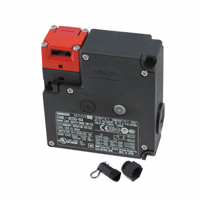
霍尼韦尔(Honeywell Sensing and Productivity Solutions)的11SM430-T是一款快动型限位开关,广泛应用于工业自动化和机械设备中。该型号具备快速动作响应、高可靠性和长寿命等特点,适用于需要精确位置检测和安全控制的场景。

典型应用包括:各类工业机械中的门锁检测、设备防护罩联锁装置、输送带系统的位置监控、自动装配线中的工件定位以及电梯或升降平台的安全限位。由于其紧凑设计和坚固外壳,11SM430-T可在恶劣工业环境中稳定运行,耐振动、防尘防溅,适合在工厂车间、物流分拣系统及自动化仓储设备中使用。

此外,该限位开关常用于安全控制系统中,确保设备在异常情况下及时断电或停机,保障操作人员与设备安全。其快动机构能实现迅速通断,提高控制精度与响应速度,是工业安全与自动化控制中的关键元件。
| 参数 | 数值 |
| 产品目录 | |
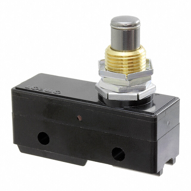
| 描述 | SW PLUNGER SPDT 1A SOLDER 125V |
| 产品分类 | |
| 品牌 | Honeywell Sensing and Control |
| 数据手册 | |
| 产品图片 |
|
| 产品型号 | 11SM430-T |
| rohs | 无铅 / 符合限制有害物质指令(RoHS)规范要求 |
| 产品系列 | SM |
| 侵入防护 | - |
| 其它名称 | 11SM430-T-ND |
| 包装 | 散装 |
| 安装类型 | 底座安装 |
| 工作位置 | 0.330" (8.4mm) |
| 工作温度 | -55°C ~ 125°C |
| 差动行程 | 0.001" (0.025mm) |
| 开关功能 | 开-瞬时 |
| 操作力,扭矩 | 99.2gf |
| 机械寿命 | 10,000,000 次循环 |
| 标准包装 | 20 |
| 特性 | - |
| 电气寿命 | - |
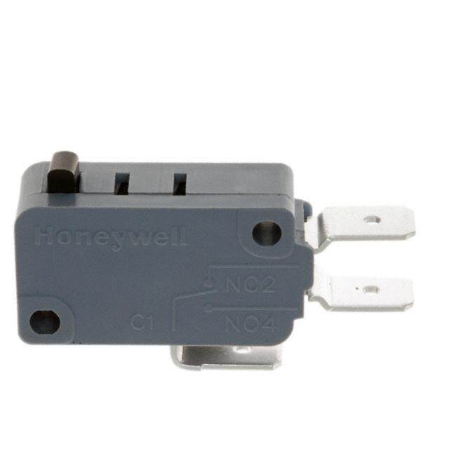
| 电路 | SPDT |
| 端子类型 | 焊接转塔 |
| 致动器类型 | 圆形(针状冲杆) |
| 超行程 | 0.005" (0.13mm) |
| 释放力 | 28gf |
| 预行程 | 0.020" (0.5mm) |
| 额定电压-AC | 125V |
| 额定电压-DC | 30V |
| 额定电流 | 1A(AC/DC) |


- 商务部:美国ITC正式对集成电路等产品启动337调查
- 曝三星4nm工艺存在良率问题 高通将骁龙8 Gen1或转产台积电
- 太阳诱电将投资9.5亿元在常州建新厂生产MLCC 预计2023年完工
- 英特尔发布欧洲新工厂建设计划 深化IDM 2.0 战略
- 台积电先进制程称霸业界 有大客户加持明年业绩稳了
- 达到5530亿美元!SIA预计今年全球半导体销售额将创下新高
- 英特尔拟将自动驾驶子公司Mobileye上市 估值或超500亿美元
- 三星加码芯片和SET,合并消费电子和移动部门,撤换高东真等 CEO
- 三星电子宣布重大人事变动 还合并消费电子和移动部门
- 海关总署:前11个月进口集成电路产品价值2.52万亿元 增长14.8%


PDF Datasheet 数据手册内容提取
SM SERIES 004959 Issue 4 MICRO SWITCH Premium Subminiature Basic Switches DESCRIPTION FEATURES The industry-defining name in snap- • Industry-leading mechanical life of up action switches, Honeywell MICRO to 10,000,000 operations SWITCH premium subminiature • Selection of actuation, electrical switches are designed for repeatability termination, and operating and enhanced product life. The MICRO characteristics along with high- SWITCH SM Series delivers consistent temperature construction options performance within a range of • Wide temperature range of conditions. -54°C to 204°C [-65°F to 400°F] • MIL-PRF-8805 qualified listings in a The MICRO SWITCH SM Series’ small lightweight, small package size and light weight are combined with • FAA-PMA approvals for commercial ample electrical capacity, precision aircraft operation, and extended life. Featuring POTENTIAL APPLICATIONS • Choice of silver or gold-plated, or gold high precision and repeatability, the • Precision switch assemblies for bifurcated contacts to handle a variety SM Series offers gold contacts for low- commercial aircraft to monitor doors of electrical load requirements energy switching and gold bifurcated for “closed” and “locked” position • UL/CSA, cUL, ENEC, and CE approvals contacts for maximum reliability. • Landing gear monitor Bifurcated contacts provide parallel • Precision switch assemblies for VALUE TO CUSTOMERS redundancy within the SM switch. commercial cockpit applications • Industry-leading life cycle rating for pushbuttons, toggle, or joystick The SM switch is available for power- reduces the need to assemblies duty switching up to 11 A (Vac) or 1/4 replace switches over life in an OEM • Precision switch assemblies in military HP (Vac). platform – reducing applications total system cost • Assemblies for industrial pressure • Low operating forces DIFFERENTIATION switches and temperature switches • Mil-qualified listings • Very wide temperature range allows • Power generation fuel level (gas • Life of up to 10,000,000 cycles for years of reliable performance in the and oil) harshest of conditions • MIL-PRF-8805 qualified listings • Operating forces as low as 0,06 N [6 g] and differential travel as low as PORTFOLIO 0,025 mm [0.001 in] delivers The SM Series of premium consistent, precise switch subminiature basic switches characteristics are a part of a strong offering of submins including SX Series (premium) and ZM, ZM1, ZD, ZX, and ZW Series (standard) switches.
MICRO SWITCH PREMIUM SUBMINIATURE BASIC SWITCHES, SM SERIES TABLE 1. SPECIFICATIONS CHARACTERISTIC PARAMETER low operating force to 2 oz. max; power load switching capability to 11 A; motor load handling capacity to 1/4 Differentiator HP (Vac) Ampere rating 0.1 A to 11 A Circuitry SPDT Operating force 0.04 oz to 2 oz Termination quick connect, solder, pcb Actuator pin plunger, straight lever, roller lever, simulated roller lever, paddle lever Voltage 115 Vac, 125 Vac, 250 Vac, 30 Vdc Agency approvals UL, CE, CSA, ENEC, MIL-PRF-8805, FAA-PMA Agency file information CE: 61058-1; UL: E12252; CSA: LR41372 Operating temperature -54°C to 121°C [-65°F to 250°F]; select catalog listings 204°C [400°F] Contacts silver, gold plated, bifurcated gold Housing phenolic Sealing sealed plunger on 411SM Series, other SM Series not weather sealed up to 10,000,000 operations for 11SM listings Mechanical life up to 80,000 operations for 1SM/41SM listings up to 1,000,000 operations for gold bifurcated contact Size 12,7 mm H x 6,35 mm W x 20,3 mm L [0.5 in H x 0.25 in W x 0.8 in L] Electrical data and UL codes Table 2. UL Electrical Ratings TABLE 2. UL ELECTRICAL RATINGS CODE CIRCUITRY ELECTRICAL DATA AND UL CODES 5 A res., 3 A ind., (sea level), J SPDT 5 A res., 2.5 A ind., (50,000 feet), 28 Vdc. UL rating: 5 A, 250 Vac K SPDT UL rating: 5 A, 125 or 250 Vac M SPDT UL rating: 11 A and 1/4 hp, 125 or 250 Vac N SPDT 1 A res., 0.5 A ind., 30 Vdc. UL rating: 1 A, 125 Vac P SPDT 1 A res., 30 Vdc. UL rating: .1 A, 125 Vac 5 A res., 3 A ind., 2.4 A lamp load (sea level), R SPDT 5 A res., 2.5 A ind., 2.4 A lamp load, (50,000 feet), 28 Vdc. 5 A res., 5 A ind., 1.5 A lamp load, 115 Vac. 60 Hz (sea level) S SPDT UL rating: 4 A, 250 Vac 2 sensing.honeywell.com
MICRO SWITCH PREMIUM SUBMINIATURE BASIC SWITCHES, SM SERIES O.F. • Operating force R.F. • Release force P.T. • Pretravel O.T. • Overtravel D.T. • Differential travel O.P. • Operating position TABLE 3. MICRO SWITCH SM SERIES ORDER GUIDE • PIN PLUNGER L al U cd s CLaisttailnogg Recommended For ectria anCode NO [.oFz.] RN.F .[ mozin]. Pm.Tm. m [ianx]. Om.Tm. m [iinn]. mmD. T[.in] mOm.P [.i *n] Elat D 0.1 A 0,83 to 1,39 0,51 0,13 8,38 11SM1077-T Gold-plated contacts 0,28 [1] 0,1 [0.004] P [3 to 5] [0.020] [0.005] [0.330] Bifurcated gold contacts, 0.1 A 0,83 to 1,39 0,51 0,076 8,38 12SM604-T 0,28 [1] 0,1 [0.004] reduced rating P [3 to 5] [0.020] [0.003] [0.330] 1 A 0,83 to 1,39 0,51 0,13 8,38 11SM23-T Gold-plated contacts 0,28 [1] 0,1 [0.004] N [3 to 5] [0.020] [0.005] [0.330] Enhanced reliability 1 A 0,83 to 1,39 0,51 0,076 8,38 12SM4-T 0,28 [1] 0,1 [0.004] (bifurcated gold contacts) N [3 to 5] [0.020] [0.003] [0.330] 4 A 0,51 0,13 0,051 8,38 11SM701-T Lower force 0,56 [2] 0,14 [0.5] S [0.020] [0.005] [0.002] [0.330] 5 A 0,83 to 1,39 0,51 0,13 8,38 11SM1-T General purpose 0,28 [1] 0,1 [0.004] J [3 to 5] [0.020] [0.005] [0.330] Operating temps to 121°C 5 A 0,83 to 1,39 0,51 0,13 8,38 11SM3-T 0,28 [1] 0,1 [0.004] [250°F] J [3 to 5] [0.020] [0.005] [0.330] Operating temps to 204°C 5 A 0,83 to 1,39 0,51 0,13 8,38 11SM244-T 0,28 [1] 0,1 [0.004] [400°F] for 100 hours [3 to 5] [0.020] [0.005] [0.330] 5 A 0,97 [3.5] 0,51 0,13 0,025 8,38 11SM401-T Less differential travel 0,28 [1] K max. [0.020] [0.005] [0.001] [0.330] 21SM284-T2 MIL-PRF-8805 5 A 0,83 to 1,39 0,76 0,13 8,38 0,28 [1] 0,1 [0.004] (MS25085-2) applications R [3 to 5] [0.030] [0.005] [0.330] MIL-PRF-8805 21SM284 5 A 0,83 to 1,39 0,76 0,13 8,38 applications, solder 0,28 [1] 0,1 [0.004] (MS25085-1) R [3 to 5] [0.030] [0.005] [0.330] terminals Enhanced stability under 5 A 0,83 to 1,39 0,51 0,13 8,38 22SM1-T 0,28 [1] 0,1 [0.004] varying humidity J [3 to 5] [0.020] [0.005] [0.330] 11 A 0,83 to 1,39 0,76 0,13 8,38 41SM1-T Up to 11 A, 1/4 HP (ac) 0,28 [1] 0,1 [0.004] M [3 to 5] [0.030] [0.005] [0.330] 5 A 0,83 to 2,09 0,51 0,13 8,38 411SM1 Sealed plunger construction 0,28 [1] 0,1 [0.004] K [3 to 7.5] [0.020] [0.005] [0.330] Sealed plunger construc- 1 A 0,83 to 2,09 0,51 0,13 8,38 411SM23 0,28 [1] 0,1 [0.004] tion, gold contacts N [3 to 7.5] [0.020] [0.005] [0.330] * except where stated ±0,38 mm [±0.015 in] Sensing and Internet of Things 3
MICRO SWITCH PREMIUM SUBMINIATURE BASIC SWITCHES, SM SERIES O.F. • Operating force R.F. • Release force P.T. • Pretravel O.T. • Overtravel D.T. • Differential travel O.P. • Operating position TABLE 4. MICRO SWITCH SM SERIES ORDER GUIDE • INTEGRAL LEVER CLaisttailnogg Recommended For Electrical Data and UL Codes NO [.oFz.] NmR [. ioFn.z. ] Pm.Tm. m [ianx]. Om.Tm. m [iinn]. mmD. T[.in] mOm.P [.i *n] 7,24 mm [0.285 in] straight 5 A 0,39 0,07 2,16 0,51 0,48 8,64 mm ±1,5 mm 311SM1-T lever J [1.4] [0.25] [0.085] [0.020] [0.019] [0.34 in ±0.060 in] 7,24 mm [0.285 in] straight 1 A 0,39 0,07 2,16 0,51 0,48 8,64 mm ±1,5 mm 311SM23-T lever, gold contacts N [1.4] [0.25] [0.085] [0.020] [0.019] [0.34 in ±0.060 in] 7,24 mm [0.285 in] straight 4 A 0,16 0,03 2,16 0,51 0,36 8,64 mm ±1,5 mm 311SM701-T lever, lower force S [0.57] [0.11] [0.085] [0.020] [0.014] [0.34 in ±0.060 in] 14,35 mm [0.565 in] straight 5 A 0,31 0,05 3,05 0,66 0,69 8,51 mm ±2 mm 311SM2-T lever J [1.1] [0.18] [0.12] [0.026] [0.027] [0.335 in ±0.08 in] 14,35 mm [0.565 in] straight 1 A 0,31 0,05 3,05 0,66 0,69 8,51 mm ±2 mm 311SM43-T lever, gold contacts N [1.1] [0.18] [0.12] [0.026] [0.027] [0.335 in ±0.08 in] 14,35 mm [0.565 in] straight 4 A 0,11 0,02 3,05 0,66 0,38 8,51 mm ±2 mm 311SM702-T lever, lower force S [0.4] [0.07] [0.12] [0.026] [0.015] [0.335 in ±0.08 in] 44,8 mm [1.765 in] straight 5 A 0,15 0,02 7,87 1,45 2,8 7,11 mm ±4,3 mm 311SM3-T lever J [0.53] [0.07] [0.31] [0.057] [0.11] [0.28 in ±0.17 in] 44,8 mm [1.765 in] straight 1 A 0,15 0,02 7,87 1,45 2,8 7,11 mm ±4,3 mm 311SM17-H58 lever, gold contacts N [0.53] [0.07] [0.31] [0.057] [0.11] [0.28 in ±0.17 in] 44,8 mm [1.765 in] straight 4 A 0,06 0,01 7,87 1,45 1,78 7,11 mm ±4,3 mm 311SM703-T lever, lower force S [0.2] [0.04] [0.31] [0.057] [0.07] [0.28 in ±0.17 in] 6,38 mm [0.251 in] simulat- 5 A 0,39 0,07 2,16 0,46 0,48 11,7 mm ±1,5 mm 311SM4-T ed roller lever J [1.4] [0.25] [0.085] [0.018] [0.019] [0.46 in ±0.06 in] 6,38 mm [0.251 in] simu- lated 1 A 0,39 0,07 2,16 0,46 0,48 11,7 mm ±1,5 mm 311SM25-T roller lever, gold contacts N [1.4] [0.25] [0.085] [0.018] [0.019] [0.46 in ±0.06 in] 6,38 mm [0.251 in] simulat- 4 A 0,16 0,03 2,16 0,46 0,33 11,7 mm ±1,5 mm 311SM704-T ed roller lever, lower force S [0.57] [0.11] [0.085] [0.018] [0.013] [0.46 in ±0.06 in] 13,6 mm [0.535 in] simulat- 5 A 0,31 0,05 3,05 0,66 0,69 11,56 mm ±2 mm 311SM5-T ed roller lever J [1.1] [0.18] [0.12] [0.026] [0.027] [0.455 in ±0.08 in] 13,6 mm [0.535 in] simulat- 4 A 0,11 0,02 3,05 0,66 0,38 11,56 mm ±2 mm 311SM705-T ed roller lever, lower force S [0.4] [0.07] [0.12] [0.026] [0.015] [0.455 in ±0.08 in] 6,38 mm [0.251 in] roller 5 A 0,39 0,07 2,16 0,46 0,48 14,2 mm ±1,5 mm 311SM6-T lever J [1.4] [0.25] [0.085] [0.018] [0.019] [0.56 in ±0.06 in] 6,38 mm [0.251 in] roller 1 A 0,39 0,07 2,16 0,46 0,48 14,2 mm ±1,5 mm 311SM68-T lever, gold contacts N [1.4] [0.25] [0.085] [0.018] [0.019] [0.56 in ±0.06 in] 6,38 mm [0.251 in] roller 4 A 0,16 0,03 2,16 0,46 0,33 14,2 mm ±1,5 mm 311SM706-T lever, lower force S [0.57] [0.11] [0.085] [0.018] [0.013] [0.56 in ±0.06 in] 13,6 mm [0.535 in] roller 5 A 0,31 0,05 3,05 0,66 0,69 14,1 mm ±2 mm 311SM7-T lever J [1.1] [0.18] [0.12] [0.026] [0.027] [0.555 in ±0.08 in] 5 A 1,95 0,56 5,54 0,76 0,76 8,89 mm ±0,76 mm 111SM1-T Leaf actuator J [7] [2] [0.218] [0.03] [0.03] [0.35 in ±0.03 in] 1 A 1,95 0,56 5,54 0,76 0,76 8,89 mm ±0,76 mm 111SM17-T Leaf actuator gold contacts N [7] [2] [0.218] [0.03] [0.03] [0.35 in ±0.03 in] 5 A 1,95 0,56 5,56 0,76 0,64 14,3 mm ±0,76 mm 111SM2-T Flexible leaf with roller J [7] [2] [0.219] [0.03] [0.025] [0.562 in ±0.03 in] Flexible leaf with roller, gold 1 A 1,95 0,56 5,56 0,76 0,64 14,3 mm ±0,76 mm 111SM23-T contacts N [7] [2] [0.219] [0.03] [0.025] [0.562 in ±0.03 in] 4 sensing.honeywell.com
MICRO SWITCH PREMIUM SUBMINIATURE BASIC SWITCHES, SM SERIES TABLE 5. NUMERIC DESIGNATIONS TABLE 5, CONTINUED. NUMERIC DESIGNATIONS FOR MICRO SWITCH SM SERIES/ORDER GUIDE FOR MICRO SWITCH SM SERIES/ORDER GUIDE PREFIX DESCRIPTION SUFFIX DESCRIPTION 1SM Standard pin plunger construction, up to 80,000 23 Gold contacts operations 400 Low differential travel series 11SM Long-life pin plunger construction, up to 500 Reverse terminal designation 10,000,000 operations 700 Low force series 12SM Gold bifurcated contacts 1000 Gold alloy 21SM Same as 1SM (formerly had DAP material) 22SM Same as 11SM (formerly had DAP material) 23SM Same as 12SM (formerly had DAP material) 41SM 11 A construction (11SM construction) 101SM 1SM with an integral leaf actuator 111SM 11SM with an integral spring leaf 112SM 12SM with an integral spring leaf 122SM 22SM with an integral spring leaf 151SM 51SM with an integral spring leaf 301SM 1SM with an integral rigid lever 302SM 1SM with an integral roller lever 311SM Integral rigid lever 321SM 21SM with an integral rigid lever 322SM 22SM with an integral rigid lever 401SM Dust/splash resistant 1SM 411SM Dust/splash resistant 11SM 412SM Dust/splash resistant 12SM Sensing and Internet of Things 5
MICRO SWITCH PREMIUM SUBMINIATURE BASIC SWITCHES, SM SERIES TABLE 6. SM SERIES • STANDARD ACTUATOR OPTIONS, SCREW TERMINALS, AND DIMENSIONS (MM/IN) Pin plunger, T terminals Pin plunger, Solder terminals Integral leaf lever Integral roller lever Integral levers NOTE: The two mounting holes accept pins or screws of 2,21 mm (0.087 in) maximum diameter MICRO SWITCH SM SERIES AVAILABLE TERMINALS Mounting torque: 0,26 Nm [2.3 in-lb] max. 6 sensing.honeywell.com
MICRO SWITCH PREMIUM SUBMINIATURE BASIC SWITCHES, SM SERIES MICRO SWITCH JS SERIES AUXILIARY ACTUATORS FOR THE MICRO SWITCH SM SERIES SWITCHES (stainless steel actuator and hardware) Description Actuator Operting Release Pretravel Overtravel Differential Operating Free Length Force Force min. max. min. Travel max. Point Position max. max. Straight leaf 16,8 mm 2,78 N 0,56 N 1,98 mm 0,38 mm 0,38 mm 8,89 mm 11,3 mm 2 [0.66 in] [10 oz] [2 oz] [0.078 in] [0.015 in] [0.015 in] ±0,38 mm [0.445 in] - S J [0.350 in ±0.015 in] Roller leaf 15 mm 2,78 N 0,83 N 1,98 mm 0,38 mm 0,38 mm 14,2 mm 16,9 mm 5 (bronze [0.59 in] [10 oz] [3 oz] [0.078 in] [0.015 in] [0.015 in] ±0,38 mm [0.665 in] - S roller) [0.56 in J ±0.015 in Formed leaf 14,7 mm 2,78 N 0,56 N 2,39 mm 0,79 mm 0,38 mm 9,65 mm 12,7 mm 7 (simulated [0.58 in] [10 oz] [2 oz] [0.094 in] [0.031 in] [0.015 in] ±0,38 mm [0.50 in] - S roller) [0.380 in J ±0.015 in] Straight lever 26,2 mm 0,28 N 0,04 N 3,18 mm 0,76 mm 0,76 mm 10,3 mm – 0 2 [1.03 in]* [1 oz] [0.14 oz] [0.125 in] [0.030 in] [0.030 in] [0.41 in] 2 S- approx. approx. J Roller lever 25,4 mm 0,28 N 0,04 N 3,18 mm 0,76 mm 0,76 mm 14,3 mm – 6 4 2 (steel roller) [1.00 in]* [1 oz] [0.14 oz] [0.125 in] [0.030 in] [0.030 in] [0.56 in] - S approx. approx. J Formed lever 25,4 mm 0,28 N 0,04 N 3,18 mm 0,76 mm 0,76 mm 11,6 mm – 1 2 (simulated [1.00 in]* [1 oz] [0.14 oz] [0.125 in] [0.030 in] [0.030 in] [0.46 in] 2 - roller) approx. approx. S J Tandem leaf 5,3 mm 5,00 N 2,78 N 2,36 mm 0,15 mm 0,38 mm 8,89 mm 10,5 mm D* [0.21 in] [18 oz] [10 oz] [0.093 in] [0.006 in] [0.015 in] ±0,38 mm [0.41 in] * 3 [0.350 in 3 - ±0.015 in] S J Tandem 4,3 mm 11,1 N 4,45 N 2,36 mm 0,13 mm 0,38 mm 14,5 mm 16,1 mm D* leaf (bronze [0.17 in] [40 oz] [16 oz] [0.093 in] [0.005 in] [0.015 in] ±0,38 mm [0.63 in] * 1 roller) [0.57 in 3 - ±0.015 in] S J ** Travel characteristics on tandem actuators vary with actual basic switch characteristics NOTE: Above actuators should be used below 300°F * “A” measurement is from pivot point of lever to the point indicated on drawing D Plated steel machine screws Sensing and Internet of Things 7
ADDITIONAL MATERIALS WARRANTY/REMEDY m WARNING The following associated literature is Honeywell warrants goods of its PERSONAL INJURY available at sensing.honeywell.com: manufacture as being free of defective DO NOT USE these products as safety • Product installation instructions materials and faulty workmanship or emergency stop devices or in any during the applicable warranty period. other application where failure of the • Product range guide Honeywell’s standard product warranty product could result in personal injury. • Aerospace range guide applies unless agreed to otherwise by Failure to comply with these • Applying basic switches Honeywell in writing; please refer to your instructions could result in death or • Low energy switching guide order acknowledgment or consult your serious injury. • Product application-specific local sales office for specific warranty information details. If warranted goods are returned m WARNING – Application Note: Central Vacuum to Honeywell during the period of MISUSE OF System coverage, Honeywell will repair or replace, DOCUMENTATION at its option, without charge those items – Application Note: Electronic Taping that Honeywell, in its sole discretion, • The information presented in this Machine product sheet is for reference only. finds defective. The foregoing is buyer’s – Application Note: Sensors and Do not use this document as a sole remedy and is in lieu of all other Switches in Sanitary Valves product installation guide. warranties, expressed or implied, • Complete installation, operation, – Application Note: Sensors and including those of merchantability and maintenance information Switches in Oil Rig Applications and fitness for a particular purpose. is provided in the instructions – Application Note: Sensors and In no event shall Honeywell be liable supplied with each product. Switches for Potential Medical for consequential, special, or indirect Failure to comply with these Applications damages. instructions could result in death or serious injury. While Honeywell may provide application assistance personally, through our literature and the Honeywell web site, it is buyer’s sole responsibility to determine the suitability of the product in the application. Specifications may change without notice. The information we supply is believed to be accurate and reliable as of this writing. However, Honeywell assumes no responsibility for its use. FOR MORE INFORMATION Honeywell Sensing and Internet of Things services its customers through a worldwide network of sales offices and distributors. For application assistance, current specifications, pricing, or the nearest Authorized Distributor, visit sensing.honeywell.com or call: International +815 618 3231 USA/Canada +302 613 4491 Honeywell Sensing and Internet of Things 9680 Old Bailes Road Fort Mill, SC 29707 004959-4-EN | 4 | 03/20 honeywell.com © 2020 Honeywell International Inc. All rights reserved.