 Datasheet下载
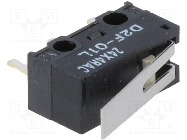
- 型号: D2F-01L
- 制造商: Omron Electronics LLC
- 库位|库存: xxxx|xxxx
- 要求:
| 数量阶梯 | 香港交货 | 国内含税 |
| +xxxx | $xxxx | ¥xxxx |
查看当月历史价格
查看今年历史价格
D2F-01L产品简介:
ICGOO电子元器件商城为您提供D2F-01L由Omron Electronics LLC设计生产,在icgoo商城现货销售,并且可以通过原厂、代理商等渠道进行代购。 D2F-01L价格参考¥9.09-¥9.09。Omron Electronics LLCD2F-01L封装/规格:快动,限位开关, 。您可以下载D2F-01L参考资料、Datasheet数据手册功能说明书,资料中有D2F-01L 详细功能的应用电路图电压和使用方法及教程。
Omron Electronics Inc-EMC Div的D2F-01L是一款快动限位开关,广泛应用于各种工业自动化和机械设备中。以下是其主要应用场景:

 1. 自动化生产线
   在自动化生产线上,D2F-01L可以用于检测工件的位置或设备的运动状态。例如,在传送带上安装该开关,可以精确检测到工件是否到达指定位置,从而触发下一步操作,如抓取、加工或包装等。其快速响应特性确保了生产线的高效运行。

 2. 机器人技术
   在工业机器人中,D2F-01L可以用作位置传感器,帮助机器人确定关节或末端执行器的位置。通过安装在机械臂的关键部位,它可以实时监测机械臂的动作范围,防止超限运动,确保机器人的安全性和精度。

 3. 包装机械
   包装机械中,D2F-01L可以用于检测包装材料或成品的位置。例如,在装箱机或封箱机上,该开关可以检测纸箱是否到位,或者包装袋是否正确放置,从而触发下一步动作,如封口或贴标签。

 4. 电梯与升降设备
   在电梯系统中,D2F-01L可以用作门限位开关,检测电梯门是否完全关闭或打开。它还可以用于检测轿厢是否到达指定楼层,确保电梯的安全运行。同样,在其他升降设备(如货梯、自动扶梯)中,该开关也可以用于位置检测和安全控制。

 5. 输送系统
   输送系统中,D2F-01L可以用于检测货物是否到达指定位置,或者检测输送带是否正常运行。通过安装在输送带的关键节点,它可以及时反馈信息给控制系统,避免货物堆积或输送带卡顿。

 6. 注塑机与压铸机
   在注塑机和压铸机中,D2F-01L可以用于检测模具的开合状态,确保模具在正确的位置进行注塑或压铸操作。此外,它还可以用于检测顶针或其他移动部件的位置,确保设备的安全运行。

 7. 物流仓储系统
   在自动化仓库中,D2F-01L可以用于检测货物存储架的位置,或者检测堆垛机是否到达指定位置。这有助于提高仓储系统的效率和准确性,减少人为错误。

总之,D2F-01L凭借其快速响应、高可靠性和紧凑设计,成为各类工业自动化设备中不可或缺的元件,适用于需要精确位置检测和安全控制的应用场景。
| 参数 | 数值 |
| 产品目录 | |
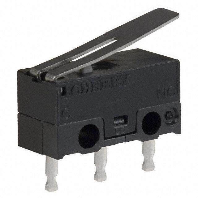
| 描述 | LEVER SWITCH PCB SPDT .1A 30V基本/快动开关 HNG LVR STD uV/C PCB |
| 产品分类 | |
| 品牌 | Omron Electronics |
| 产品手册 | |
| 产品图片 |
|
| rohs | 符合RoHS无铅 / 符合限制有害物质指令(RoHS)规范要求 |
| 产品系列 | 基本/快动开关,Omron Electronics D2F-01LD2F |
| mouser_ship_limit | 该产品可能需要其他文件才能进口到中国。 |
| 数据手册 | |
| 产品型号 | D2F-01L |
| 产品培训模块 | http://www.digikey.cn/PTM/IndividualPTM.page?site=cn&lang=zhs&ptm=19281http://www.digikey.cn/PTM/IndividualPTM.page?site=cn&lang=zhs&ptm=25458 |
| 产品目录绘图 |
|
| 产品目录页面 | |
| 产品种类 | 基本/快动开关 |
| 侵入防护 | IP40 |
| 其它名称 | D2F01L |
| 其它有关文件 | |
| 包装 | 散装 |
| 单位重量 | 500 mg |
| 商标 | Omron Electronics |
| 安装 | Through Hole |
| 安装类型 | 通孔 |
| 工作位置 | 0.268" (6.8mm) |
| 工作力 | 0.5 N |
| 工作温度 | -25°C ~ 65°C |
| 工厂包装数量 | 500 |
| 差动行程 | 0.020" (0.5mm) |
| 开关功能 | ON - (OFF), OFF - (ON) |
| 执行器 | Lever |
| 操作力,扭矩 | 80gf |
| 机械寿命 | 1,000,000 次循环 |
| 标准包装 | 500 |
| 特性 | - |
| 电压额定值DC | 30 V |
| 电气寿命 | 30,000 次循环 |
| 电流额定值 | 100 mA |
| 电路 | 单刀双掷 |
| 端子类型 | PC 引脚 |
| 端接类型 | Solder Pin |
| 类型 | Standard |
| 系列 | D2F |
| 致动器类型 | 按片,直形 |
| 触点形式 | SPDT |
| 超行程 | 0.022" (0.55mm) |
| 释放力 | 5gf |
| 零件号别名 | 365750 9774718 D2F01LNCD2F01LOEI12 |
| 预行程 | - |
| 额定电压-AC | - |
| 额定电压-DC | 30V |
| 额定电流 | 100mA(DC) |


- 商务部:美国ITC正式对集成电路等产品启动337调查
- 曝三星4nm工艺存在良率问题 高通将骁龙8 Gen1或转产台积电
- 太阳诱电将投资9.5亿元在常州建新厂生产MLCC 预计2023年完工
- 英特尔发布欧洲新工厂建设计划 深化IDM 2.0 战略
- 台积电先进制程称霸业界 有大客户加持明年业绩稳了
- 达到5530亿美元!SIA预计今年全球半导体销售额将创下新高
- 英特尔拟将自动驾驶子公司Mobileye上市 估值或超500亿美元
- 三星加码芯片和SET,合并消费电子和移动部门,撤换高东真等 CEO
- 三星电子宣布重大人事变动 还合并消费电子和移动部门
- 海关总署:前11个月进口集成电路产品价值2.52万亿元 增长14.8%


PDF Datasheet 数据手册内容提取
D2F Ultra Subminiature Basic Switch Ultra Subminiature Basic Switch with plenty of terminal variations ●Incorporating a snapping mechanism made with two highly precise split springs that ensures long D durability. 2 F ●Using insertion molded terminals that prevents flux penetration. ●In addition to self-clinching PCB, left-angled, right-angled terminals, 2 types of soldering terminals are available. ●Lineup of 5A type for high load applications. RoHS Compliant Model Number Legend @@@@ D2F- 1 2 3 4 1. Ratings 4. Terminals None : 125 VAC 3A None : PCB terminals (Straight) 125 VAC 1A (Low operating force) -T : Self-clinching PCB terminals 01 : 30 VDC 0.1A -A : PCB terminals (Right-angled) 5 : 250 VAC 5A -A1 : PCB terminals (Left-angled) -D3 : Solder terminals 2. Maximum Operating Force (OF) -D : Compact solder terminals None : 1.47 N {150 gf} F : 0.74 N {75 gf} Note. The given values are for pin plunger models only. 3. Actuator None : Pin plunger L : Hinge lever L2 : Hinge Roller Lever L3 : Simulated roller lever (R1.3) L30 : Simulated roller lever (R2.5) 1
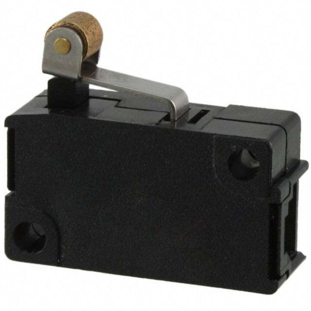
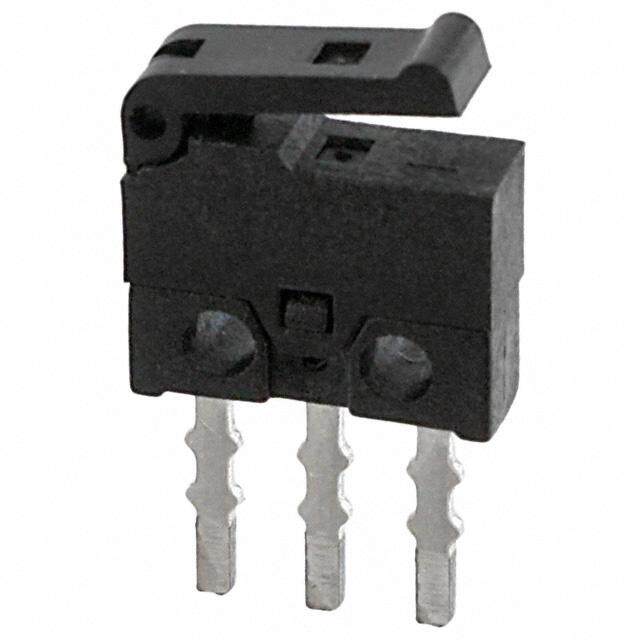
D2F Ultra Subminiature Basic Switch List of Models Ratings 3 A 1 A 0.1 A 5 A Maximum Operating Force (OF) * General Purpose Low Operating Force General Purpose Low Operating Force General Purpose Actuator Terminals 1.47 N {150 gf} 0.74 N {75 gf} 1.47 N {150 gf} 0.74 N {75 gf} 1.47 N {150 gf} Pin plunger PCB terminals (Standard) D2F D2F-F D2F-01 D2F-01F D2F-5 Self-clinching PCB terminals D2F-T D2F-F-T D2F-01-T D2F-01F-T PCB terminals (Right-angled) D2F-A D2F-F-A D2F-01-A D2F-01F-A PCB terminals (Left-angled) D2F-A1 D2F-F-A1 D2F-01-A1 D2F-01F-A1 - Solder terminals D2F-D3 D2F-F-D3 D2F-01-D3 D2F-01F-D3 Compact solder terminals D2F-D D2F-F-D D2F-01-D D2F-01F-D D Hinge lever PCB terminals (Standard) D2F-L D2F-FL D2F-01L D2F-01FL D2F-5L 2 Self-clinching PCB terminals D2F-L-T D2F-FL-T D2F-01L-T D2F-01FL-T F PCB terminals (Right-angled) D2F-L-A D2F-FL-A D2F-01L-A D2F-01FL-A PCB terminals (Left-angled) D2F-L-A1 D2F-FL-A1 D2F-01L-A1 D2F-01FL-A1 - Solder terminals D2F-L-D3 D2F-FL-D3 D2F-01L-D3 D2F-01FL-D3 Compact solder terminals D2F-L-D D2F-FL-D D2F-01L-D D2F-01FL-D Hinge roller PCB terminals (Standard) D2F-L2 D2F-FL2 D2F-01L2 D2F-01FL2 lever Self-clinching PCB terminals D2F-L2-T D2F-FL2-T D2F-01L2-T D2F-01FL2-T PCB terminals (Right-angled) D2F-L2-A D2F-FL2-A D2F-01L2-A D2F-01FL2-A - PCB terminals (Left-angled) D2F-L2-A1 D2F-FL2-A1 D2F-01L2-A1 D2F-01FL2-A1 Solder terminals D2F-L2-D3 D2F-FL2-D3 D2F-01L2-D3 D2F-01FL2-D3 Compact solder terminals D2F-L2-D D2F-FL2-D D2F-01L2-D D2F-01FL2-D Simulated roller PCB terminals (Standard) D2F-L3 D2F-FL3 D2F-01L3 D2F-01FL3 D2F-5L3 lever (R1.3) Self-clinching PCB terminals D2F-L3-T D2F-FL3-T D2F-01L3-T D2F-01FL3-T PCB terminals (Right-angled) D2F-L3-A D2F-FL3-A D2F-01L3-A D2F-01FL3-A PCB terminals (Left-angled) D2F-L3-A1 D2F-FL3-A1 D2F-01L3-A1 D2F-01FL3-A1 - Solder terminals D2F-L3-D3 D2F-FL3-D3 D2F-01L3-D3 D2F-01FL3-D3 Compact solder terminals D2F-L3-D D2F-FL3-D D2F-01L3-D D2F-01FL3-D Simulated roller PCB terminals (Standard) D2F-L30 D2F-FL30 D2F-01L30 D2F-01FL30 lever (R2.5) Self-clinching PCB terminals D2F-L30-T D2F-FL30-T D2F-01L30-T D2F-01FL30-T PCB terminals (Right-angled) D2F-L30-A D2F-FL30-A D2F-01L30-A D2F-01FL30-A - PCB terminals (Left-angled) D2F-L30-A1 D2F-FL30-A1 D2F-01L30-A1 D2F-01FL30-A1 Solder terminals D2F-L30-D3 D2F-FL30-D3 D2F-01L30-D3 D2F-01FL30-D3 Compact solder terminals D2F-L30-D D2F-FL30-D D2F-01L30-D D2F-01FL30-D * OF are value for Pin plunger. Contact Form Contact Specifications ●SPDT D2F models Item Model D2F-01 models D2F-5 models Specifications Crossbar Contact Material Silver alloy Gold alloy Gap (standard value) 0.25 mm Minimum applicable load (see note) * 100 mA at 5 VDC 1 mA at 5 VDC COM NO NC * Please refer to "Using Micro Loads" in "Precautions" for more information on the minimum applicable load. Ratings Model D2F models D2F-01 models D2F-5 models Maximum Operating 1.47N (General-purpose) 0.74N (Low Operating Force) 1.47N (General-purpose) 0.74N (Low Operating Force) 1.47N (General-purpose) Force (OF) Rated voltage Resistive load 125 VAC 3 A 1 A - - 30 VDC 2 A 0.5 A 0.1 A - 250 VAC - - 5 A Note.The above rating values apply under the following test conditions. (1) Ambient temperature: 20±2°C (2) Ambient humidity: 65±5% (3) Operating frequency: 30 operations/min Approved Safety Standard The items shown in the "List of Models" above are not standard approved models. Consult your OMRON sales representative for specific models with standard approvals. UL (UL1054) /CSA (CSA C22.2 No.55) Rated voltage Model D2F (General-purpose) D2F (Low operating force) D2F-01 125 VAC 3 A 1 A - 30 VDC 2 A 0.5 A 0.1 A 2
D2F Ultra Subminiature Basic Switch Characteristics Model D2F models D2F-5 models D2F-01 models Item 0.74 N (Low operating force) 1.47 N (General-purpose) 1.47 N (General-purpose) Pin plunger models: 1 mm to 500 mm/s, Permissible operating speed Lever models: 5 mm to 500 mm/s Pin plunger models: 200 operations/min, Permissible operating Mechanical Lever models: 100 operations/min frequency Electrical 30 operations/min Insulation resistance 100 MΩ min. (at 500 VDC with insulation tester) Contact resistance (initial value) 100 mΩ max. 50 mΩ max. 30 mΩ max. Between terminals of the same 600 VAC 50/60 Hz for 1min D polarity 2 Dielectric strength Between current-carrying metal 1,500 VAC 50/60 Hz for 1min F parts and ground Between each terminal and 1,500 VAC 50/60 Hz for 1min non-current-carrying metal parts Vibration resistance * 1 Malfunction 10 to 55 Hz, 1.5-mm double amplitude Durability 1,000 m/s2 {approx. 100G} max. Shock resistance Malfunction * 1 300 m/s2 {approx. 30G} max. Mechanical 1,000,000 operations min. (60 operations/min) Durability * 2 100,000 operations 30,000 operations min. 10,000 operations min. Electrical min. (30 operations/min) (30 operations/min) (30 operations/min) Degree of protection IEC IP40 -40°C to +85°C (at ambient humidity 60% max.) Ambient operating temperature (with no icing or condensation) Ambient operating humidity 85% max. (for +5°C to +35°C) Weight Approx. 0.5 g (pin plunger models) Note.The data given above are initial values. *1. The values are at Free Position and Total Travel Position values for pin plunger, and Total Travel Position value for lever. Close or open circuit of the contact is 1ms max. *2. For testing conditions, consult your OMRON sales representative. Terminals/Appearances (Unit: mm) ●PCB terminals (Straight) ●Self-clinching PCB terminals <PCB Mounting Dimensions (Reference)> 5.8±0.15 3-1.2 dia. holes 5.08±0.1 1.5 1.5 12.8±0.15 1.6±0.15 3.5 3.4 3.15 6.5±0.1 0.9 0.4 3.15 6.5±0.1 0.9 0.4±0.05 1.5 5.08 5.08 5.8±0.15 5.08 5.08 1.25±0.15 12.8±0.15 12.8±0.15 5.8±0.15 ●PCB terminals (Right-angled) ●PCB terminals (Left-angled) 1.5 1.5 2.6±0.2 2.6±0.2 3.15 3.15 6.5±0.1 0.9 5.8±0.15 0.4 6.5±0.1 0.9 0.4 5.8±0.15 5.08 5.08 3.1±0.2 5.08 5.08 3.1±0.2 12.8±0.15 12.8±0.15 ●Solder terminals ●Compact solder terminals 1.5 1.5 2.4 2 3.5 3.15 0.4 6.5±0.1 1.6 0.5 3.15 6.5±0.1 1.22.2 0.4 3−0.8 dia. holes 5.08 5.08 5.8±0.15 5.08 5.08 5.8±0.15 12.8±0.15 12.8±0.15 Mounting Holes (Unit: mm) 2-2 dia. mounting holes 6.5±0.15 3
D2F Ultra Subminiature Basic Switch Dimensions /Operating Characteristics (Unit: mm) The following illustrations and drawings are for D2F models with PCB terminals (straight). Self-clinching, solder, compact solder, and right-angled, left angled terminals are omitted from the following drawings. Refer to the previous page for these terminals. When ordering, replace @ with the code for the terminal that you need. See the "List of Models" for available combinations of models. ●Pin Plunger Models DD22FF--0@1 @ 2.2+00.12 dia.1.2125..72 PT2+00.12 dia. holes 52..79 Operating Model DD22FF--@01 @ D2F-F@ D2F-F@ A D2F-01F@ Characteristics D2F-5 D2F-01F@ Operating Force OF Max. 1.47 N {150 gf} 0.74 N {75 gf} D2F-5 5 OP Releasing Force RF Min. 0.20 N {20 gf} 0.05 N {5 gf} D 2 2+00.12 Pretravel PT Max. 0.5 mm 0.5 mm Overtravel OT Min. 0.25 mm 0.25 mm F Movement Differential MD Max. 0.12 mm 0.12 mm Operating Position OP 5.5±0.3 mm 0.4 5.8±0.15 ●Hinge Lever Models D2F-L@ D2F-01L@ 12.8 D2F-L@ D2F-FL@ (10.8) Operating Model D2F-01L@ D2F-FL@ A D2F-01FL@ D2F-01FL@ t=0.3 * 3 Characteristics D2F-5L Operating Force OF Max. 0.78 N {80 gf} 0.25 N {25 gf} D2F-5L Releasing Force RF Min. 0.05 N {5 gf} 0.02 N {2 gf} FP OP Overtravel OT Min. 0.55 mm 0.55 mm Movement Differential MD Max. 0.5 mm 0.5 mm Free Position FP Max. 10 mm Operating Position OP 6.8±1.5 mm * Stainless-steel lever ●Simulated Roller Lever Models (R1.3) D2F-L3@ 12.7 D2F-01L3@ (7.5) Model D2F-L3@ D2F-FL3@ D2F-FL3@ A Operating D2F-01L3@ 10 D2F-01FL3@ D2F-01FL3@ Characteristics D2F-5L3 D2F-5L3 R1.3 2.1 3 t=0.3 * ORepleeraastiinngg FFoorrccee ROFF MMianx. . 00.7.085 N N { {850 ggff}} 00.3.092 NN { {420 ggff}} Overtravel OT Min. 0.5 mm 0.5 mm FP Movement Differential MD Max. 0.45 mm 0.45 mm OP Free Position FP Max. 13 mm Operating Position OP 8.5±1.2 mm * Stainless-steel lever ●Simulated Roller Lever Models (R2.5) D2F-L30@ D2F-01L30@ DD22FF--0F1LF3L03@0 @ 12.7 3.3 R2.5 A t=0.3 * OChpaerraactitnegri stics Model DD22FF--L0130L3@0 @ DD22FF--F01LF30L@30 @ 3 Operating Force OF Max. 0.54 N {55 gf} 0.3 N {31 gf} Releasing Force RF Min. 0.04 N {4 gf} 0.02 N {2 gf} Overtravel OT Min. 0.5 mm 0.5 mm FP OP Movement Differential MD Max. 0.5 mm 0.5 mm Free Position FP Max. 12.6 mm Operating Position OP 9.5±1.0 mm * Stainless-steel lever Note 1.Unless otherwise specified, a tolerance of ±0.4 mm applies to all dimensions. Note 2.The operating characteristics are for operation in the A direction ( ). 4
D2F Ultra Subminiature Basic Switch ●Hinge Roller Lever Models D2F-L2@ D2F-01L2@ 12.8 4 D2F-FL2@ (10) A 4.8 dia.×2.8 *2 Operating Model D2F-L2@ D2F-FL2@ D2F-01L2@ D2F-01FL2@ D2F-01FL2@ Characteristics (4.6) Operating Force OF Max. 0.78 N {80 gf} 0.39 N {40 gf} Releasing Force RF Min. 0.05 N {5 gf} 0.02 N {2 gf} t=0.3 *1 Overtravel OT Min. 0.55 mm 0.55 mm 4 FP Movement Differential MD Max. 0.5 mm 0.5 mm OP Free Position FP Max. 16.5 mm Operating Position OP 13±2 mm D 2 F *1. Stainless-steel lever *2. Polyacetal resin roller Note 1.Unless otherwise specified, a tolerance of ±0.4 mm applies to all dimensions. Note 2.The operating characteristics are for operation in the A direction ( ). Precautions ★Please refer to "Basic Switches Common Precautions" for correct use. Cautions Correct Use ●Soldering ●Mounting (cid:129)Terminal connection Use M2 mounting screws with plane washers or spring washers When soldering, make sure that the temperature of the to securely mount the Switch. Tighten the screws to a torque of soldering iron tip is not higher than 300°C, and complete the 0.08 to 0.1 N·m {0.8 to 1 kgf·cm}. soldering within 3 seconds. Do not apply any external force for ●Using Micro Loads 1 minute after soldering. Soldering at an excessively high temperature or soldering for more than 3 seconds may Using a model for ordinary loads to open or close the contact of deteriorate the characteristics of the Switch. a micro load circuit may result in faulty contact. Use models that (cid:129)Connecting to PCB terminal Boards operate in the following range. However, even when using micro When using automatic soldering baths, we recommend load models within the following operating range, if inrush soldering at 260°C ±5°C within 5 seconds. Make sure that the current occurs when the contact is opened or closed, it may liquid surface of the solder does not flow over the edge of the increase the contact wear and so decrease durability. Therefore, board. insert a contact protection circuit where necessary. The When soldering terminals manually, perform soldering within 3 minimum applicable load is the N-level reference value. This seconds at iron tip temperature not higher than 350°C. Do not value indicates the malfunction reference level for the reliability apply any external force for at least 1 minute after soldering. level of 60% (λ60). When applying solder, keep the solder away from the case of (JIS C5003) the Switch and do not allow solder or flux to flow into the case. The equation, λ60=0.5×10⁻⁶/operation, indicates that the 1 estimated malfunction rate is less than operations 2,000,000 with a reliability level of 60%. V) e ( oltag 30 0.16 mA 16.6 mA 100 mA V 24 Operating Operating range range for for micro load general-load models models D2F-01 D2F 12 5 1 mA 0 0.1 1 10 100 1,000 Current (mA) 5
D2F Ultra Subminiature Basic Switch D 2 F (cid:129) Application examples provided in this document are for reference only. In actual applications, confirm equipment functions and safety before using the product. (cid:129) Consult your OMRON representative before using the product under conditions which are not described in the manual or applying the product to nuclear control systems, railroad systems, aviation systems, vehicles, combustion systems, medical equipment, amusement machines, safety equipment, and other systems or equipment that may have a serious influence on lives and property if used improperly. Make sure that the ratings and performance characteristics of the product provide a margin of safety for the system or equipment, and be sure to provide the system or equipment with double safety mechanisms. Note: Do not use this document to operate the Unit. OMRON Corporation Electronic and Mechanical Components Company Contact: www.omron.com/ecb Cat. No. B036-E1-12 0318(0207)(O) 6
Mouser Electronics Authorized Distributor Click to View Pricing, Inventory, Delivery & Lifecycle Information: O mron: D2F-L2 D2F-01 D2F-FL D2F-01L-A D2F-01L-A1 D2F-FL-A D2F-01F D2F-01L D2F-01L3 D2F-FL-A1 D2F-L D2F-01F-D D2F-L-A D2F-F D2F-01FL3-A1 D2F-01FL3-A D2F-01FL D2F-01FL3 D2F-FL3 D2F-L3 D2F-01FL2 D2F-01L2 D2F-FL2 D2F-01F-T D2F-01-T D2F-F-T D2F-T D2F-01FL-T D2F-01L-T D2F-FL-T D2F-01FL3-T D2F- FL3-T D2F-L3-T D2F-01L2-T D2F-L2-T D2F-01-D D2F-F-D D2F-D D2F-01L-D D2F-FL-D D2F-L-D D2F-01FL3-D D2F-01L3-D D2F-FL3-D D2F-L3-D D2F-01FL2-D D2F-FL2-D D2F-L2-D D2F-01F-A D2F-01-A D2F-01FL-A D2F-01L3-A D2F-FL3-A D2F-L3-A D2F-01L2-A D2F-FL2-A D2F-L2-A D2F-01F-A1 D2F-01-A1 D2F-F-A1 D2F-A1 D2F-01FL-A1 D2F-L-A1 D2F-01L3-A1 D2F-FL3-A1 D2F-L3-A1 D2F-01L2-A1 D2F-FL2-A1 D2F-L2-A1 D2F- 01L10 D2F-01L3-D2 D2F-01L76 D2F-L111 D2F-L151 D2F-L26 D2F-01FL-D D2F-01L2-D D2F D2F-L20 D2F- 01L26-D D2F-01L3-D3 D2F-01L-D3 D2F-L20-D D2F-L-D3 D2F-L20-A1 D2F-01-D3 D2F-FL3-D3 D2F-L2-D3 D2F- L-T D2F-F-A D2F-01FL30 D2F-01FL30-D3 D2F-01FL3-D3 D2F-01L30 D2F-01L30-A D2F-01L30-A1 D2F-01L30-D D2F-01L30-D3 D2F-L30 D2F-L30-A1