
 Datasheet下载
- 型号: D2SW-P2L1M
- 制造商: Omron Electronics LLC
- 库位|库存: xxxx|xxxx
- 要求:
| 数量阶梯 | 香港交货 | 国内含税 |
| +xxxx | $xxxx | ¥xxxx |
查看当月历史价格
查看今年历史价格
D2SW-P2L1M产品简介:
ICGOO电子元器件商城为您提供D2SW-P2L1M由Omron Electronics LLC设计生产,在icgoo商城现货销售,并且可以通过原厂、代理商等渠道进行代购。 D2SW-P2L1M价格参考¥36.18-¥96.05。Omron Electronics LLCD2SW-P2L1M封装/规格:快动,限位开关, Switch SPDT Chassis Mount。您可以下载D2SW-P2L1M参考资料、Datasheet数据手册功能说明书,资料中有D2SW-P2L1M 详细功能的应用电路图电压和使用方法及教程。
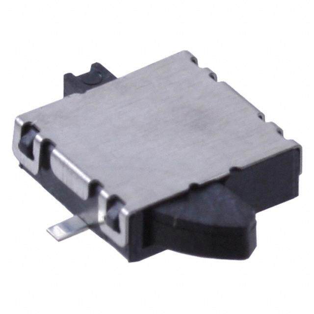
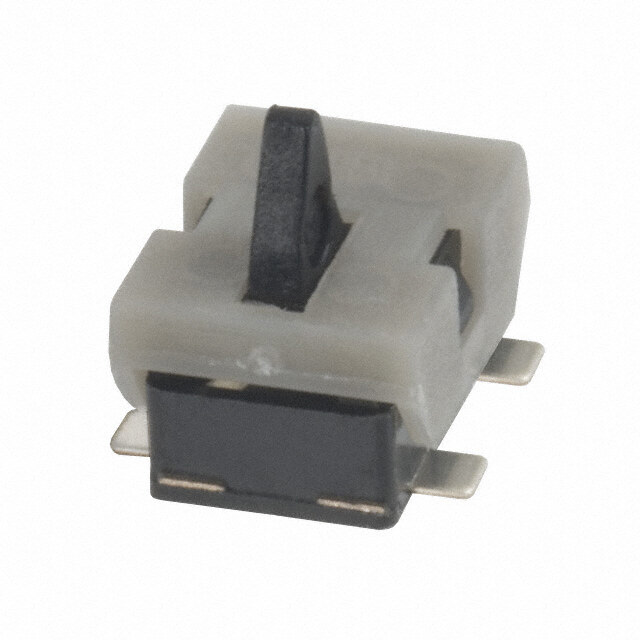
欧姆龙(Omron Electronics Inc-EMC Div)型号D2SW-P2L1M是一款快动限位开关,具有高可靠性与快速动作响应特性。该开关适用于需要精确位置检测和设备安全控制的工业自动化场景。

典型应用包括:自动化生产线中的机械位置检测,如传送带启停控制、气缸或液压缸行程终点确认;包装机械中用于检测盖板开闭状态或物料到位信号;以及印刷、纺织、塑料成型等设备中实现运动部件的限位保护。其紧凑设计和坚固外壳适合在空间受限或环境较恶劣的场合使用。

D2SW-P2L1M具备快速通断功能,可有效防止电弧损伤,提升开关寿命,同时支持高频操作,确保控制系统响应迅速。常用于需要频繁动作且对稳定性要求较高的设备中,如机器人工作站、装配机和自动门系统。

此外,该限位开关符合多项国际安全标准,适用于全球范围内的工业设备制造,是实现设备安全联锁和位置反馈的理想选择。
| 参数 | 数值 |
| IP等级 | IP 67 |
| 品牌 | Omron Electronics |
| 产品目录 | 机电产品 |
| 描述 | 基本/快动开关 Subminiature Basic Switch |
| 产品分类 | |
| 产品手册 | |
| 产品图片 |
|
| rohs | 符合RoHS |
| 产品系列 | 基本/快动开关,Omron Electronics D2SW-P2L1M |
| mouser_ship_limit | 该产品可能需要其他文件才能进口到中国。 |
| 产品型号 | D2SW-P2L1M |
| 产品种类 | 基本/快动开关 |
| 商标 | Omron Electronics |
| 安装 | Panel |
| 工作力 | 0.6 N |
| 工厂包装数量 | 20 |
| 开关功能 | ON - (OFF), OFF - (ON) |
| 执行器 | Lever |
| 电压额定值AC | 250 V |
| 电流额定值 | 2 A |
| 端接类型 | Wire Leads |
| 类型 | Miniature |
| 系列 | D2SW-P |
| 触点形式 | SPDT |
| 零件号别名 | 646715 |


- 商务部:美国ITC正式对集成电路等产品启动337调查
- 曝三星4nm工艺存在良率问题 高通将骁龙8 Gen1或转产台积电
- 太阳诱电将投资9.5亿元在常州建新厂生产MLCC 预计2023年完工
- 英特尔发布欧洲新工厂建设计划 深化IDM 2.0 战略
- 台积电先进制程称霸业界 有大客户加持明年业绩稳了
- 达到5530亿美元!SIA预计今年全球半导体销售额将创下新高
- 英特尔拟将自动驾驶子公司Mobileye上市 估值或超500亿美元
- 三星加码芯片和SET,合并消费电子和移动部门,撤换高东真等 CEO
- 三星电子宣布重大人事变动 还合并消费电子和移动部门
- 海关总署:前11个月进口集成电路产品价值2.52万亿元 增长14.8%


PDF Datasheet 数据手册内容提取
D2SW-P Sealed Subminiature Basic Switch Sealed Basic Switch with Simplified Construction, Mounting Compatible with SS and D2SW Series. ●Rubber packing construction keeps dust off and (cid:14832) offers temporary waterproofing protection (IEC (cid:14814) IP67). (cid:14847) ●Switch rating of 2 A at 250 VAC possible with a (cid:14851) single-leaf movable spring. Models for micro (cid:14844)- loads are also available. ●Solder, quick-connect terminals (#110), PCB terminals, and molded lead wires are available. ●UL, CSA, VDE safety standard approved models are available upon request. RoHS Compliant Model Number Legend @ @ @ @ D2SW-P1 2 3 4 1. Ratings 3. Contact form 2 : 250 VAC 2 A None : SPDT 01 : 30 VDC 0.1 A -2 : SPST-NC (Molded lead wire models only) -3 : SPST-NO (Molded lead wire models only) 2. Actuator None : Pin plunger 4. Terminals L1 : Hinge lever H : Solder terminals L2 : Hinge roller lever D : Self-clinching PCB terminals L3 : Simulated roller lever T : Quick-connect terminals (#110) M : Molded lead wires List of Models (Contact your dealer for detailed delivery date.) Ratings 2 A 0.1 A Actuator Terminals Contact Form Solder terminals D2SW-P2H D2SW-P01H Quick-connect terminals (#110) SPDT D2SW-P2T D2SW-P01T PCB terminals D2SW-P2D D2SW-P01D Pin plunger SPDT D2SW-P2M D2SW-P01M Molded lead wires SPST-NC D2SW-P2-2M D2SW-P01-2M SPST-NO D2SW-P2-3M D2SW-P01-3M Solder terminals D2SW-P2L1H D2SW-P01L1H Quick-connect terminals (#110) D2SW-P2L1T D2SW-P01L1T Hinge lever SPDT PCB terminals D2SW-P2L1D D2SW-P01L1D Molded lead wires D2SW-P2L1M D2SW-P01L1M Solder terminals D2SW-P2L2H D2SW-P01L2H Quick-connect terminals (#110) D2SW-P2L2T D2SW-P01L2T Hinge roller lever SPDT PCB terminals D2SW-P2L2D D2SW-P01L2D Molded lead wires D2SW-P2L2M D2SW-P01L2M Solder terminals D2SW-P2L3H D2SW-P01L3H Quick-connect terminals (#110) D2SW-P2L3T D2SW-P01L3T Simulated roller lever SPDT PCB terminals D2SW-P2L3D D2SW-P01L3D Molded lead wires D2SW-P2L3M D2SW-P01L3M Separator (Sold Separately), Terminal Connector (Sold Separately) Refer to "Micro Switch Common Accessories" 1
D2SW-P Sealed Subminiature Basic Switch Contact Form ●SPDT ●SPST-NC (Molded lead wire models ●SPST-NO (Molded lead wire only) models only) The color in parentheses indicates the color of the COM NO NC COM NC COM NO lead wire. (Black)(Blue)(Red) (Black) (Red) (Black) (Blue) (cid:14832) (cid:14814) Contact Specifications Ratings (cid:14847) (cid:14851) Item Model D2SW-P2 models D2SW-P01 models Model Rated voltage Resistive load (cid:14844)- Specification Rivet Crossbar 250 VAC D2SW-P2 models 2 A Contact Material Silver Gold alloy 30 VDC Gap (Standard value) 0.5 mm 125 VAC D2SW-P01 models 0.1 A Minimum applicable load 30 VDC 160 mA at 5 VDC 1 mA at 5 VDC (reference value)* Note.The above rating values apply under the following test conditions. * Please refer to "●Using Micro Loads" in "Precautions" for more (1) Ambient temperature: 20±2°C information on the minimum applicable load. (2) Ambient humidity: 65±5% (3) Operating frequency: 20 operations/min Approved Safety Standards The items shown in the "List of Models" are not standard approved models. Consult your OMRON sales representative for specific models with standard approvals. UL (UL1054/CSA C22.2 No.55) VDE (EN61058-1) Rated voltage Model D2SW-P2 D2SW-P01 Rated voltage Model D2SW-P2 D2SW-P01 125 VAC - 0.1 A 125 VAC - 0.1 A 250 VAC 2 A - 250 VAC 2 A - 30 VDC 2 A 0.1 A 30 VDC 2 A 0.1 A Testing conditions: 5E4 (50,000 operations) T55 (0°C to 55°C) Characteristics Item Model D2SW-P2 models D2SW-P01 models Permissible operating speed 0.1 mm to 500 mm/s (for pin plunger models) Permissible operating Mechanical 120 operations/min frequency Electrical 30 operations/min Insulation resistance 100 mΩ min. (500 VDC with insulation tester) Contact resistance Terminal models 50 mΩ max. 100 mΩ max. (initial value) Molded lead wire models 100 mΩ max. 150 mΩ max. Between terminals of the 1,000 VAC 50/60 Hz for 1 min 600 VAC 50/60 Hz for 1 min same polarity Between current-carrying 1,500 VAC 50/60 Hz for 1 min Dielectric strength *1 metal parts and ground Between each terminals and non-current-carrying 1,500 VAC 50/60 Hz for 1 min metal parts Vibration resistance *2 Malfunction 10 to 55 Hz, 1.5-mm double amplitude Destruction 1,000 m/s2 {approx. 100G} max. Shock resistance Malfunction *2 300 m/s2 {approx. 30G} max. Mechanical 1,000,000 operations min. (60 operations/min) Durability *3 Electrical 50,000 operations min. (20 operations/min) 200,000 operations min. (20 operations/min) Terminal models IEC IP67 (excluding the terminals on terminal models) Degree of protection Molded lead wire models IEC IP67 Degree of protection against electric shock Class I Proof tracking index (PTI) 250 Ambient operating temperature -20°C to +70°C (at ambient humidity of 60% max.) (with no icing or condensation) Ambient operating humidity 85% max. (for +5 to +35°C) Weight Approx. 2 g (for pin plunger models with terminals) Note.The data given above are initial values. *1. The dielectric strength shown in the table indicates values for models with a Separator. *2. The values are at Free Position and Total Travel Position values for pin plunger, and Total Travel Position value for lever. Close or open circuit of contact is 1 ms max. *3. For testing conditions, consult your OMRON sales representative. 2
D2SW-P Sealed Subminiature Basic Switch Terminals and Shapes (Unit: mm) ●Solder terminals ●Quick-connect terminals (#110) C NC NC C NC NC 3.3±0.1 3.3±0.1 7.3 11 7.1 3.2 3-1.6 dia. holes 0.5 3-2.8 0.5 2.15 8.55 6.4±0.2 7.6±0.2 7.6±0.2 6.4±0.2 15.5 5.15 9.5±0.1 (cid:14832) 5.15 9.5±0.1 19.8±0.2 (cid:14814) 19.8±0.2 (cid:14847) (cid:14851) ●PCB terminals ●Molded lead wires (cid:14844)- C NC C NC NC 1.8 NC 3.3±0.1 9.2 3.9 3-1.2 1.3 COM (Black) 1.85 8.8±106.2.1±0.2 3-0.8 0.5 (AWG22, UL1007) 300±10 6.4±0.2 6.4±0.2 NC (Red) 5.15 9.5±0.1 (AWG22, UL1007) 19.8±0.2 (5) <PCB Mounting Dimensions (Reference)> 0.7 NO (Blue) 5.15 9.5±0.1 (AWG22, UL1007) 16.1±0.1 21.2 8.8±0.1 3-1.35〜1.5 dia. Mounting Holes (Unit: mm) 2-M2.3 screw holes 9.5±0.1 3
D2SW-P Sealed Subminiature Basic Switch Dimensions / Operating Characteristics (Unit: mm) The illustrations and drawings are for solder terminal models. Refer to "Terminals and Shapes" of previous page for details on models with quick-connect terminals (#110) or PCB terminals or molded lead wires. The @ in the model number is for the contact form code or the terminal code. See the "List of Models" for available combinations of models. ●Pin Plunger Models D2SW-P2@@ A 7.55±0.2 D2SW-P01@@ PT2.5±0.07 dia. 111...888 dddiiiaaa...2.35 +- 00 .. 00 57 5 dia. Model D2SW-P2@@ Operating characteristics D2SW-P01@@ OP C NC 6.9 7.7 Operating Force OF Max. 1.8 N {184 gf} (cid:14832) NC Releasing Force RF Min. 0.2 N {20 gf} 3.3±0.1 (cid:14814)(cid:14847) 2.35+-00..00575 7.3 POrveetrrtarvaevle l POTT MMainx.. 00..64 mmmm (cid:14851) 2.135.2 8.55 3-1.6 dia. holes 0.5 Movement Differential MD Max. 0.15 mm (cid:14844)- 15.5 6.4±0.2 Operating Position OP 8.4±0.3mm 5.15 9.5±0.1 19.8±0.2 ●Hinge Lever Models D2SW-P2L1@@ A D2SW-P01L@@ t=0.3 Stainless-steel lever 14.5±0.6 2.35 +- 00 .. 00 75 5 dia. Model D2SW-P2L1@@ 2.5±0.07 dia. Operating characteristics D2SW-P01L1@@ 6.9 7.7 OPFP ORepleeraastiinngg FFoorrccee ORFF MMainx.. 00..065 N N { 6{51 ggff}} 2.35+-00..00755 C NC NC 3.3±0.1 Overtravel OT Min. 0.8 mm 7.3 Movement Differential MD Max. 0.8 mm 3.2 Free Position FP Max. 13.6 mm 2.15 8.55 3-1.6 dia. holes 0.5 Operating Position OP 8.8±0.8 mm 15.5 6.4±0.2 5.15 9.5±0.1 19.8±0.2 ●Hinge Roller Lever Models D2SW-P2L2@@ A 4.8x3.2 dia. Polyacetal resin roller D2SW-P01L2@@ t=0.3 Stainless-steel lever 14.5±0.6 Model D2SW-P2L2@@ 2.5±0.07 dia. 222...333555 ++--- 000000 ...... 000000 777555 555 dddiiiaaa... Operating characteristics D2SW-P01L2@@ OP FP Operating Force OF Max. 0.6 N {61 gf} 6.9 7.7 Releasing Force RF Min. 0.05 N {5 gf} 2.35 +- 00 .. 00 75 5 C NC NC 3.3±0.1 Overtravel OT Min. 0.8 mm 7.3 Movement Differential MD Max. 0.8 mm Free Position FP Max. 19.3 mm 2.135.2 8.55 3-1.6 dia. holes 0.5 Operating Position OP 14.5±0.8 mm 15.5 6.4±0.2 5.15 9.5±0.1 19.8±0.2 ●Simulated Roller Lever Models D2SW-P2L3@@ A D2SW-P01L3@@ t=0.3 Stainless-steel lever R1.3 15.8±0.6 2.35 +- 00 .. 00 75 5 dia. Model D2SW-P2L3@@ 2.5±0.07 dia. Operating characteristics D2SW-P01L3@@ OP FP Operating Force OF Max. 0.6 N {61 gf} 6.9 7.7 Releasing Force RF Min. 0.05 N {5 gf} 2.35 +- 00 .. 00 75 5 C NC NC 3.3±0.1 Overtravel OT Min. 0.8 mm 7.3 Movement Differential MD Max. 0.8 mm 3.2 Free Position FP Max. 15.5 mm 2.15 8.55 3-1.6 dia. holes 0.5 Operating Position OP 10.7±0.8 mm 15.5 6.4±0.2 5.15 9.5±0.1 19.8±0.2 Note 1.Unless otherwise specified, a tolerance of ±0.4 mm applies to all dimensions. Note 2.The operating characteristics are for operation in the A direction ( ). 4
D2SW-P Sealed Subminiature Basic Switch Precautions ★ Please refer to "Basic Switches Common Precautions" for correct use. ●Side-actuated (Cam/Dog) Operation Cautions •When using a cam or dog to operate the Switch, factors such ●Degree of Protection as the operating speed, operating frequency, push-button •Do not use this product in water. indentation, and material and shape of the cam or dog will Although this models satisfy the test conditions for the affect the durability of the Switch. Confirm performance standard given below, this test is to check the ingress of water specifications under actual operation conditions before using into the switch enclosure after submerging the Switch in water the Switch in applications. for a given time. Satisfying this test condition does not mean Correct Use (cid:14832) that the Switch can be used in water. (cid:14814) JIS C0920: (cid:14847) Degrees of protection provided by enclosures of electrical ●Mounting (cid:14851) apparatus (IP Code) •Turn OFF the power supply before mounting or removing the (cid:14844)- IEC 60529: Switch, wiring, or performing maintenance or inspection. Degrees of protection provided by enclosures (IP Code) Failure to do so may result in electric shock or burning. Degree of protection: IP67 •Use M2.3 mounting screws with plane washers or spring (check water intrusion after immersion washers to securely mount the Switch. for 30 min submerged 1 m Tighten the screws to a torque of 0.23 to 0.26 N·m {2.3 to underwater) 2.7kgf·cm}. Exceeding the specified torque may result in •Do not operate the Switch when it is exposed to water spray, deterioration of the sealing or damage. or when water drops adhere to the Switch surface, or during ●Operating Body sudden temperature changes, otherwise water may intrude •Use an operating body with low frictional resistance and of a into the interior of the Switch due to a suction effect. •Prevent the Switch from coming into contact with oil and shape that will not interfere with the sealing rubber, otherwise chemicals. the plunger may be damaged or the sealing may deteriorate. Otherwise, damage to or deterioration of Switch materials may With the pin plunger models, set the Switch so that the plunger result. can be pushed in from directly above. Since the plunger is •Do not use the Switch in areas where it is exposed to silicon covered with a rubber cap, applying a force from lateral adhesives, oil, or grease, otherwise faulty contact may result directions may cause damage to the plunger or reduction in due to the generation of silicon oxide. the sealing capability. Since the plunger is covered with a •The environment-resistant performance of the switch differs rubber cap, applying a force from lateral directions may cause depending on operating loads, ambient atmospheres, and damage to the plunger or reduction in the sealing capability. installation conditions, etc. Please perform an operating test of the switch in advance under actual usage conditions. ●Soldering •Connecting to Solder Terminals When soldering the lead wire to the terminal, first insert the lead wire conductor through the terminal hole and then conduct soldering. Complete the soldering at the iron tip temperature between ●Handling 350 to 400°C within 3 seconds, and do not apply any external •Do not handle the Switch in a way that may cause damage to force for 1 minute after soldering. Soldering at a excessively the sealing rubber. high temperature or soldering for more than 3 s may •When handling the Switch, ensure that uneven pressure or, as deteriorate the characteristics of the Switch. •Connecting to Quick-connect Terminals shown in the following diagram, pressure in a direction other Wire the quick-connect terminals (#110) with receptacles. than the operating direction is not applied to the Actuator, Insert the terminals straight into the receptacles. Applying otherwise the Actuator or Switch may be damaged, or excessive external force laterally may cause deformation of durability may be decreased. terminals and may damage the housings. •Connecting to PCB terminals When using automatic soldering baths, we recommend soldering at 260±5°C within 5 seconds. Make sure that the liquid surface of the solder does not flow over the edge of the board. When soldering terminals manually, complete the soldering at the iron tip temperature between 350 to 400°C within 3 ●Wiring Molded Lead Wire Models seconds, and do not apply any external force for 1 minute after •When wiring molded lead wire models, ensure that there is no soldering. When applying solder, keep the solder away from force applied on the wire or that there are no sharp bends near the case of the Switch and do not allow solder or flux to flow the parts where the wire is drawn out. into the case. Otherwise, damage to the Switch or deterioration in the sealing may result. 5
D2SW-P Sealed Subminiature Basic Switch ●Using Micro Loads •Using a model for ordinary loads to open or close the contact of a micro load circuit may result in faulty contact. Use models that operate in the following range. However, even when using micro load models within the following operating range, if inrush current occurs when the contact is opened or closed, it may increase the contact wear and so decrease durability. Therefore, insert a contact protection circuit where necessary. (cid:14832) The N-level reference value applies for the minimum (cid:14814) (cid:14847) applicable load.This value indicates the malfunction reference (cid:14851) level for the reliability level of 60% (λ60). (JIS C5003) (cid:14844)- The equation λ60=0.5×10⁻⁶/operations indicates that the 1 estimated malfunction rate is less than operations 2,000,000 with a reliability level of 60%. V) ge ( 0.16 mA 26 mA 100 mA a 30 olt V 24 Operating Operating range for range for micro load models general-load D2SW-P01 models D2SW-P2 12 5 1 mA 100 mA160 mA 0 0.1 1 10 100 1,000 Current (mA) (cid:129) Application examples provided in this document are for reference only. In actual applications, confirm equipment functions and safety before using the product. (cid:129) Consult your OMRON representative before using the product under conditions which are not described in the manual or applying the product to nuclear control systems, railroad systems, aviation systems, vehicles, combustion systems, medical equipment, amusement machines, safety equipment, and other systems or equipment that may have a serious influence on lives and property if used improperly. Make sure that the ratings and performance characteristics of the product provide a margin of safety for the system or equipment, and be sure to provide the system or equipment with double safety mechanisms. Note: Do not use this document to operate the Unit. OMRON Corporation ELECTRONIC AND MECHANICAL COMPONENTS COMPANY Contact: www.omron.com/ecb Cat. No. B109-E1-04 0812(0207)(O) 6
Mouser Electronics Authorized Distributor Click to View Pricing, Inventory, Delivery & Lifecycle Information: O mron: D2SW-P2L3H D2SW-P2L3M D2SW-P01D D2SW-P01T D2SW-P2L2H D2SW-P2T D2SW-P01L3D D2SW- P01L3T D2SW-P01L3B D2SW-P01L3M D2SW-P2H D2SW-P01L1H D2SW-P01L2H D2SW-P2L2T D2SW-P01L1- 2M D2SW-P01L3-3M D2SW-P2L1H D2SW-P01L1M D2SW-P2L1M D2SW-P2M D2SW-P01M