ICGOO在线商城 > 0805B103K101N

 Datasheet下载
- 型号: 0805B103K101N
- 制造商: Novacap
- 库位|库存: xxxx|xxxx
- 要求:
| 数量阶梯 | 香港交货 | 国内含税 |
| +xxxx | $xxxx | ¥xxxx |
查看当月历史价格
查看今年历史价格
0805B103K101N产品简介:
ICGOO电子元器件商城为您提供0805B103K101N由Novacap设计生产,在icgoo商城现货销售,并且可以通过原厂、代理商等渠道进行代购。 提供0805B103K101N价格参考以及Novacap0805B103K101N封装/规格参数等产品信息。 你可以下载0805B103K101N参考资料、Datasheet数据手册功能说明书, 资料中有0805B103K101N详细功能的应用电路图电压和使用方法及教程。
| 参数 | 数值 |
| 品牌 | Novacap |
| 产品目录 | 无源元件 |
| 描述 | 多层陶瓷电容器MLCC - SMD/SMT .01uF 1000V 10% Tol X7R 0805 |
| 产品分类 | |
| 产品手册 | |
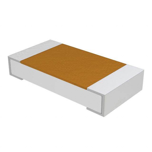
| 产品图片 |
|
| rohs | RoHS 合规性豁免 |
| 产品系列 | MLCC,多层陶瓷电容器MLCC - SMD/SMT,Novacap 0805B103K101N |
| 产品型号 | 0805B103K101N |
| 产品 | General Type MLCCs |
| 产品种类 | 多层陶瓷电容器MLCC - SMD/SMT |
| 商标 | Novacap |
| 外壳代码-in | 0805 |
| 外壳代码-mm | 2012 |
| 外壳宽度 | 1.27 mm |
| 外壳长度 | 2.03 mm |
| 外壳高度 | 1.37 mm |
| 容差 | 10 % |
| 封装 | Bulk |
| 封装/箱体 | 0805 (2012 metric) |
| 最大工作温度 | + 125 C |
| 最小工作温度 | - 55 C |
| 温度系数/代码 | +/- 15 % |
| 电介质 | X7R |
| 电压额定值 | 100 V |
| 电压额定值DC | 100 V |
| 电容 | 0.1 uF |
| 端接类型 | SMD/SMT |


- 商务部:美国ITC正式对集成电路等产品启动337调查
- 曝三星4nm工艺存在良率问题 高通将骁龙8 Gen1或转产台积电
- 太阳诱电将投资9.5亿元在常州建新厂生产MLCC 预计2023年完工
- 英特尔发布欧洲新工厂建设计划 深化IDM 2.0 战略
- 台积电先进制程称霸业界 有大客户加持明年业绩稳了
- 达到5530亿美元!SIA预计今年全球半导体销售额将创下新高
- 英特尔拟将自动驾驶子公司Mobileye上市 估值或超500亿美元
- 三星加码芯片和SET,合并消费电子和移动部门,撤换高东真等 CEO
- 三星电子宣布重大人事变动 还合并消费电子和移动部门
- 海关总署:前11个月进口集成电路产品价值2.52万亿元 增长14.8%


PDF Datasheet 数据手册内容提取
Commercial Chip - X7R 16Vdc to 10kVdc A range of commercial MLC chip capacitors in Stable EIA Class Standard EIA case sizes and available C/V values are listed II dielectric. Class II X7R chips are used as decoupling, by-pass, below - special sizes, thicknesses and other voltage ratings are filtering and transient voltage suppression elements and exhibit available; please contact the sales office for information. +/-15% temperature coefficient and predictable variation of electrical properties with time, temperature and voltage. Designed for surface mount application with nickel barrier terminations making them suitable for solder wave and reflow solder board attachment as well as vapor phase attachment for part sizes 2225 or smaller. Silver-palladium terminations are also available for hybrid use with conductive epoxy. Capacitance and voltage selection for popular chip sizes Capacitance and voltage selection for popular chip sizes Size 0402 0504 0603 0805 1005 1206 1210 1515 1808 1812 1825 2020 2221 2225 2520 3333 3530 4040 4540 5440 5550 6560 7565 Size Min cap. 121 121 121 121 121 121 121 151 151 151 151 151 471 471 471 471 471 471 102 102 102 102 102 102 102 222 222 Min cap. Tmax inches: 0. 024 0.044 0.035 0.054 0.054 0.064 0.065 0.130 0.065 0.080* 0.065 0.100* 0.080 0.140* 0.180 0.080 0.080 0.150* 0.180 0.250 0.250 0.300 0.300 0.300 0.300 0.300 0.300 :inches Tmax mm: 0.61 1.12 0.89 1.37 1.37 1.63 1.63 3.02 1.63 2.03 1.63 2.54 2.03 3.56 4.57 2.03 2.03 3.81 4.57 6.35 6.35 7.62 7.62 7.62 7.62 7.62 7.62 :mm 16V 562 393 273 124 154 334 474 125 684 824 125 155 185 225 185 155 225 275 355 525 525 825 905 106 126 206 256 16V 25V 472 333 223 104 124 274 474 105 564 564 105 125 155 225 155 125 185 225 325 505 505 755 805 106 106 186 226 25V 50V 472 333 223 104 124 274 474 824 394 564 824 125 155 225 155 125 185 225 325 425 425 705 755 905 106 156 206 50V 100V 472 333 223 683 823 184 334 684 274 394 564 824 125 185 155 125 155 225 275 405 405 625 685 825 905 126 186 100V 200V 222 153 103 333 473 104 184 564 184 224 334 564 824 155 125 684 105 185 225 355 355 565 625 705 825 825 156 200V 250V 152 103 682 273 393 683 124 394 124 154 224 394 684 125 105 564 824 155 185 325 325 505 605 685 805 825 126 250V 300V • • • 153 183 473 823 274 823 104 154 224 474 824 824 394 474 105 125 225 225 475 505 575 705 755 106 300V 400V • • • 123 123 273 563 224 563 823 104 184 334 564 564 274 394 684 824 125 125 255 275 305 375 545 875 400V 500V • • • 123 822 223 563 154 563 683 104 154 334 474 474 274 334 564 684 105 105 185 185 185 225 335 475 500V 600V • • • 822 822 183 393 124 393 563 683 124 224 394 274 224 274 474 394 684 684 155 155 155 225 275 395 600V 800V† • • • 472 472 103 273 823 273 333 473 683 124 274 224 124 154 334 274 474 394 684 824 105 155 225 275 800V† 1kV† • • • 272 272 682 153 563 153 223 273 473 823 154 154 823 104 224 184 334 334 564 684 684 105 155 185 1kV† 1.5kV† • • • • • 222 472 183 472 682 822 153 273 563 393 273 333 683 563 124 124 274 334 344 474 684 824 1.5kV† 2kV† • • • • • 102 222 822 272 332 472 682 123 273 273 123 153 333 273 823 683 154 184 184 274 394 474 2kV† 3kV† • • • • • • • 152 561 821 122 222 272 472 472 272 332 682 822 333 273 473 563 683 823 124 184 3kV† 4kV† • • • • • • • 122 331 391 681 122 152 272 272 152 152 332 472 183 153 223 333 393 473 823 104 4kV† 5kV† • • • • • • • • • • • • 821 182 152 821 102 222 272 123 103 123 183 223 333 473 563 5kV† 6kV† • • • • • • • • • • • • • • • • • • • 682 562 822 123 153 223 333 393 6kV† 7kV† • • • • • • • • • • • • • • • • • • • 472 472 562 822 103 153 223 273 7kV† 8kV† • • • • • • • • • • • • • • • • • • • • 332 472 682 822 123 153 223 8kV† 9kV† • • • • • • • • • • • • • • • • • • • 272 332 472 562 103 123 183 9kV† 10kV† • • • • • • • • • • • • • • • • • • • • 182 272 392 472 682 103 123 10kV† * Denotes non standard chip thickness. † Units rated above 800V may require conformal coating to preclude arcing over chip surface Order code needs to have an ’X’ inserted together with the dimension in inches e.g. X080 where dimension is 0.080” 20 | Phone: +1.661.295.5920 | www.novacap.com
Commercial Chip - X7R 16Vdc to 10kVdc l For dielectric characteristics see page 6. l For dimensions see page 12. l For termination options see pages 3 & 15. l For capacitance tolerances available see page 15. l For ordering information see page 15. Note: Maximum capacitance values are shown below as 3 digit code: 2 significant figures followed by the no. of zeros e.g. 183 = 18,000pF. Capacitance and voltage selection for popular chip sizes Capacitance and voltage selection for popular chip sizes Size 0402 0504 0603 0805 1005 1206 1210 1515 1808 1812 1825 2020 2221 2225 2520 3333 3530 4040 4540 5440 5550 6560 7565 Size Min cap. 121 121 121 121 121 121 121 151 151 151 151 151 471 471 471 471 471 471 102 102 102 102 102 102 102 222 222 Min cap. Tmax inches: 0. 024 0.044 0.035 0.054 0.054 0.064 0.065 0.130 0.065 0.080* 0.065 0.100* 0.080 0.140* 0.180 0.080 0.080 0.150* 0.180 0.250 0.250 0.300 0.300 0.300 0.300 0.300 0.300 :inches Tmax mm: 0.61 1.12 0.89 1.37 1.37 1.63 1.63 3.02 1.63 2.03 1.63 2.54 2.03 3.56 4.57 2.03 2.03 3.81 4.57 6.35 6.35 7.62 7.62 7.62 7.62 7.62 7.62 :mm 16V 562 393 273 124 154 334 474 125 684 824 125 155 185 225 185 155 225 275 355 525 525 825 905 106 126 206 256 16V 25V 472 333 223 104 124 274 474 105 564 564 105 125 155 225 155 125 185 225 325 505 505 755 805 106 106 186 226 25V 50V 472 333 223 104 124 274 474 824 394 564 824 125 155 225 155 125 185 225 325 425 425 705 755 905 106 156 206 50V 100V 472 333 223 683 823 184 334 684 274 394 564 824 125 185 155 125 155 225 275 405 405 625 685 825 905 126 186 100V 200V 222 153 103 333 473 104 184 564 184 224 334 564 824 155 125 684 105 185 225 355 355 565 625 705 825 825 156 200V 250V 152 103 682 273 393 683 124 394 124 154 224 394 684 125 105 564 824 155 185 325 325 505 605 685 805 825 126 250V 300V • • • 153 183 473 823 274 823 104 154 224 474 824 824 394 474 105 125 225 225 475 505 575 705 755 106 300V 400V • • • 123 123 273 563 224 563 823 104 184 334 564 564 274 394 684 824 125 125 255 275 305 375 545 875 400V 500V • • • 123 822 223 563 154 563 683 104 154 334 474 474 274 334 564 684 105 105 185 185 185 225 335 475 500V 600V • • • 822 822 183 393 124 393 563 683 124 224 394 274 224 274 474 394 684 684 155 155 155 225 275 395 600V 800V† • • • 472 472 103 273 823 273 333 473 683 124 274 224 124 154 334 274 474 394 684 824 105 155 225 275 800V† 1kV† • • • 272 272 682 153 563 153 223 273 473 823 154 154 823 104 224 184 334 334 564 684 684 105 155 185 1kV† 1.5kV† • • • • • 222 472 183 472 682 822 153 273 563 393 273 333 683 563 124 124 274 334 344 474 684 824 1.5kV† 2kV† • • • • • 102 222 822 272 332 472 682 123 273 273 123 153 333 273 823 683 154 184 184 274 394 474 2kV† 3kV† • • • • • • • 152 561 821 122 222 272 472 472 272 332 682 822 333 273 473 563 683 823 124 184 3kV† 4kV† • • • • • • • 122 331 391 681 122 152 272 272 152 152 332 472 183 153 223 333 393 473 823 104 4kV† 5kV† • • • • • • • • • • • • 821 182 152 821 102 222 272 123 103 123 183 223 333 473 563 5kV† 6kV† • • • • • • • • • • • • • • • • • • • 682 562 822 123 153 223 333 393 6kV† 7kV† • • • • • • • • • • • • • • • • • • • 472 472 562 822 103 153 223 273 7kV† 8kV† • • • • • • • • • • • • • • • • • • • • 332 472 682 822 123 153 223 8kV† 9kV† • • • • • • • • • • • • • • • • • • • 272 332 472 562 103 123 183 9kV† 10kV† • • • • • • • • • • • • • • • • • • • • 182 272 392 472 682 103 123 10kV† * Denotes non standard chip thickness. † Units rated above 800V may require conformal coating to preclude arcing over chip surface Order code needs to have an ’X’ inserted together with the dimension in inches e.g. X080 where dimension is 0.080” www.novacap.com | Phone: +1.661.295.5920 | 21
Chip Ordering Information y y t t e e n bili bilia Prefix Case Size Dielectric Capacitanc CapacitancTolerance Voltage Terminatio Special Thickness High ReliaTesting Packaging Marking High ReliaTest Criteri XX 1206 N 472 J 101 N X050 H T M - HB Capacitance Code 1st two digits are 1R0 = 1.0pF Special Thickness Packaging Marking sdiiggniti fdiceannot,t etsh ird 120 = 12pF None Standard thickness None Bulk None Unmarked number of zeros, as per Novacap T Tape & Reel M Marked R = decimal 471 = 470pF catalog specifications *Marking not Examples: 102 = 1,000pF X Denotes a special W Waffle Pack asivzaeisla <b l0e6 o0n3 thickness other than 273 = 0.027µF standard. Specify in inches if required. High Reliability Hi-Reliability 474 = 0.47µF (As shown above X Testing Testing Criteria = 0.050”) 105 = 1.0µF None Standard product { HB MIL-PRF-55681 Group A H High Reliability Testing HV MIL-PRF-49467 Group A Dielectric Codes H High Temp Screening HS MIL-PRF-123 Group A N C0G/NP0 Ultra Stable M C0G/NP0 Ultra Stable Magnetic Free Termination Codes F C0G/NP0 High Temp. (up to 160ºC) P Palladium Silver D C0G/NP0 High Temp. (up to 200ºC) Voltage Code K R3L Ultra Stable PR Palladium Silver* R R2D Pulse Energy 1st two digits are significant, K Solderable Palladium Silver* third digit denotes number of Y Y5V General Purpose zeros. For example: N Nickel Barrier* 100% tin Z Z5U General Purpose 160 = 16 Volts Y Nickel Barrier 90% tin, 10% lead B X7R Stable NG Nickel Barrier Gold Flash* 101 = 100 Volts C X7R Stable Magnetic Free C FlexiCap™/Nickel Barrier* 100% tin 501 = 500 Volts X BX MIL D FlexiCap™/Nickel Barrier 90% tin, 10% lead S X8R High Temp. (up to 150ºC) 102 = 1,000 Volts B Copper Barrier* 100% tin E Class II High Temp. (up to 200ºC) 502 = 5,000 Volts E Copper Barrier 90% tin, 10% lead G Class II High Temp. (up to 160ºC) 103 = 10,000 Volts S Silver* W X5R Stable * Indicates RoHS terminations RN Lead free C0G/NP0 Ultra Stable RB Lead free X7R Stable Capacitance Tolerance Codes BB X7R BME Stable BW X5R BME Stable Code Tolerance C0G/NP0 R3L R2D YZ55UV X7R BX X8R ClaIIss X5R PVosTitiCve * Not RF series N M F/D K R Y/Z B C X S E/G W P NPorneefixSt aDndeafird nchiitpions DCB ±±±000...215500pppFFF Cap. Value < 10pF ••• ••• •• RF Improved ESR Capacitor p. 23 F ±1% • • • LS Y3 Certified Safety Capacitor p. 42 - 43 G ±2% • • • • ES Y2 Certified Safety Capacitor p. 42 - 43 J ±5% • • • • • •* • •* • • ST Stacked Capacitor Assembly p. 48 - 53 K ±10% • • • • • • • • • • • • SM Stacked Hi-Rel Capacitor Assembly p. 48 - 53 M ±20% • • • • • • • • • • • • CR Cap-Rack Capacitor Array p. 54 Z +80% -20% • • • •* • RC Bleed Resistor p. 58 - 61 P +100% -0% • • • •* • www.novacap.com | Phone: +1.661.295.5920 | 15
LL TT Technical Summary WW Technical Information Primary Dielectric Types MMBB Novacap provides application notes throughout this catalog C0G/NP0: as a guide to chip selection and attachment methods. Refer Ultra stable Class I dielectric, with negligible dependence of to the Novacap Technical Brochure found at www.novacap. capacitance on temperature, voltage, frequency, and time. com for more details. This technical information includes Used in circuitry requiring very stable performance. the nature of capacitance, dielectric properties, electrical properties, classes of dielectrics, ferroelectric behavior, test X7R: standards, and high reliability test plans. Please do not Stable Class II dielectric, with predictable change in properties hesitate to contact the sales office for any product or technical across a temperature range of -55°C to +125°C. Used as assistance. blocking, decoupling, bypassing, and frequency discriminating elements. This dielectric is ferroelectric and provides higher Capacitor Size capacitance than Class I materials. Size availability is based primarily on capacitance values and voltage rating. Smaller units are generally less expensive. BX: Because mass affects the thermal shock susceptibility of chip The military specification for ceramic chip capacitors (MIL- capacitors, size selection should consider the soldering method PRF-55681) defines a mid-K stable dielectric designated as BX. used to attach the chip to the board. Sizes 1812 and smaller The BX specification has voltage temperature limits in addition can be wave, vapor phase, or reflow soldered. Larger units to temperature limits of capacitance. The BX dielectric is require reflow soldering. limited to ±15% maximum change in capacitance between Chip Selection 25°C and -55°C or +125°C and also has a voltage restriction Multilayer capacitors (MLC) are categorized by dielectric of +15% / -25% maximum change in capacitance between performance with temperature. The Temperature Coefficient 25°C and -55°C or +125°C at rated voltage. of Capacitance describes the variance of capacitance value Z5U/Y5V: with temperature. The choice of components is therefore General purpose Class III dielectrics with higher dielectric largely determined by the temperature stability required of the constant and greater variation of properties over temperature device and the size necessary for the desired capacitance value and voltage. Very high capacitance per volume is attainable and voltage rating. for general purpose applications where stability over a wide Packaging temperature range is not critical. Units are available reeled, in waffle pack, or bulk packaged. Bar coded labels are standard for reeled and bulk packaging. Dielectric er er Termination Material Termination arri arri We recommend the following Combinations B B Palladium Silver Palladium Silver Solderable Palladium Silver Nickel Barrier 100% tin Nickel Barrier 90/10% tin/lead Nickel Barrier Gold flash FlexiCap™/Nickel 100% tin FlexiCap™/Nickel 90/10% tin/lead Copper Barrier 100% tin Copper Barrier 90/10% tin/lead Solderable Silver tSNtCeion r l mdpNFlielaneicrtxak eiAtCediolta t-nBp a aR™tcroyhrpH iemweSrsi,et: h1n 0tN:0 i %cke ml atte Barrier, 100% tin plated - RoHS RoHS RoHS RoHS RoHS RoHS RoHS RoHS Y Nickel Barrier, tin-lead plated Dielectric Code P PR K N Y NG C D B E S C0G/NP0 N/RN • • • • • • • • • D FlexiCap™ Nickel Barrier, R3L K • • • • • • • • tin-lead plated X7R B/RB • • • • • • • • • B Copper Barrier 100% matte X7R BME BB • • • tin plated - RoHS X5R BME BW • • • E Copper Barrier, tin-lead BX X • • • • • • • • • plated Y5V Y • • K Solderable Palladium Silver - Z5U Z • • RoHS (suitable for conductive epoxy attach) C0G/NP0 (Mag free) M • • • • • S Solderable Silver - RoHS X7R (Mag free) C • • • • • Conductive Epoxy attachment: X8R S • • • • • • • • C0G/NP0 (160ºC) F • • • • • • • • P Palladium Silver C0G/NP0 (200ºC) D • • PR Palladium Silver - RoHS Class II (160ºC) G • • • • • • • • NG Nickel Barrier Gold Flash - Class II (200ºC) E • • RoHS (suitable for soldering attach) Pulse Power P • • • R2D R • • • www.novacap.com | Phone: +1.661.295.5920 | 3
Dielectric Characteristics X7R (B) Stable and RoHS 2013 (RB) type Operating temperature range: -55°C to 125°C %DC TEMPERATURE COEFFICIENT Temperature coefficient : ±15% DC Max. 20 Dissipation factor >25V rating: 2.5% max GE 15 UPPER LIMIT <25V rating: 3.5% max AN 10 H Insulation resistance: @ @12255ººCC:: >>1100G0GWW o ro r> >10100W00FW wFh wichheicvheer vies rl eiss sless ANCE C 50 TYPICAL CIT -5 Dielectric <200V: 250% PA -10 wvoitlthasgtaen d i n g 2 0 1 >-550000VV:: 112500%% oorr 755000VV wwhhiicchheevveerr iiss ggrreeaatteerr %CA -15 LOWER LIMIT -20 Ageing rate: <2.0% per decade -55 -35 -15 5 25 4565 85 105 125 TEMPERATURE °C Test parameters: 1KHz, 1.0 ±0.2 VRMS, 25°C X7R (C) Stable Non Magnetic Operating temperature range: -55°C to 125°C %DC TEMPERATURE COEFFICIENT Temperature coefficient: ±15% DC Max. 20 Dissipation factor >25V rating: 2.5% max GE 15 UPPER LIMIT <25V rating: 3.5% max AN 10 H Insulation resistance: @ @12255ººCC:: >>1100G0GWW o ro r> >10100W00FW wFh wichheicvheer vies rl eiss sless ANCE C 50 TYPICAL CIT -5 Dielectric <200V: 250% PA -10 wvoitlthasgtaen d i n g 2 0 1 >-550000VV:: 112500%% oorr 755000VV wwhhiicchheevveerr iiss ggrreeaatteerr %CA -15 LOWER LIMIT -20 Ageing rate: <2.0% per decade -55 -35 -15 5 25 4565 85 105 125 TEMPERATURE °C Test parameters: 1KHz, 1.0 ±0.2 VRMS, 25°C BX (X) Stable Operating temperature range: -55°C to 125°C Temperature coefficient: ±15% DC Max. %DC TEMPERATURE COEFFICIENT 20 Temp-voltage coefficient: +15% -25% DC Max. GE 15 UPPER LIMIT Dissipation factor >25V rating: 2.5% max AN 10 <25V rating: 3.5% max E CH 5 TYPICAL Insulation resistance: @25ºC: >100GW or >1000WF whichever is less ANC 0 @125ºC: >10GW or >100WF whichever is less CIT -5 Dielectric <200V: 250% APA -10 withstanding 201-500V: 150% or 500V whichever is greater %C -15 LOWER LIMIT voltage >500V: 120% or 750V whichever is greater -20 -55 -35 -15 5 25 4565 85 105 125 Ageing rate: <2.0% per decade TEMPERATURE °C Test parameters: 1KHz, 1.0 ±0.2 VRMS, 25°C X8R (S) Stable Operating temperature range: -55°C to 150°C TEMPERATURE COEFFICIENT %DC Temp. coefficient <150ºC: ±15% DC Max. 40 E G Dissipation factor >25V rating: 2.5% max AN 20 <25V rating: 3.5% max CH E C Insulation @25ºC: >100GW or >1000WF whichever is less AN 0 resistance @150ºC: >10GW or >100WF whichever is less CIT A P -20 Dielectric <200V: 250% A C withstanding 201-500V: 150% or 500V whichever is greater % voltage >500V: 120% or 750V whichever is greater -40 -55 -25 0 25 50100 75 125 150 Ageing rate: <2.0% per decade TEMPERATURE °C Test parameters: 1KHz, 1.0 ±0.2 VRMS, 25°C 6 | Phone: +1.661.295.5920 | www.novacap.com
Chip Dimensions L T W MB Dimensions - inches (mm) Size Length (L) Width (W) Max. Thickness (T)* Termination Band (MB) 0402 0.040 ± 0.004 (1.02 ± 0.102) 0.020 ± 0.004 (0.508 ± 0.102) 0.024 (0.610) 0.010 ± 0.006 (0.254 ± 0.152) 0504 0.050 ± 0.006 (1.27 ± 0.152) 0.040 ± 0.006 (1.02 ± 0.152) 0.044 (1.12) 0.014 ± 0.006 (0.356 ± 0.152) RF0505 0.055 +0.015 -0.010 (1.4 +0.38 -0.25) 0.055 ± 0.015 (1.40 ± 0.381) 0.057 (1.45) 0.014 ± 0.006 (0.356 ± 0.152) 0603 0.060 ± 0.006 (1.52 ± 0.152) 0.030 ± 0.006 (0.762 ± 0.152) 0.035 (0.889) 0.014 ± 0.006 (0.356 ± 0.152) 0805 0.080 ± 0.008 (2.03 ± 0.203) 0.050 ± 0.008 (1.27 ± 0.203) 0.054 (1.37) 0.020 ± 0.010 (0.508 ± 0.254) 0907 0.090 ± 0.008 (2.29 ± 0.203) 0.070 ± 0.008 (1.78 ± 0.203) 0.060 (1.52) 0.020 ± 0.010 (0.508 ± 0.254) 1005 0.100 ± 0.008 (2.54 ± 0.203) 0.050 ± 0.008 (1.27 ± 0.203) 0.054 (1.37) 0.020 ± 0.010 (0.508 ± 0.254) RF1111 0.110+0.025 -0.010 (2.79 +0.64 -0.25) 0.110 ± 0.015 (2.79 ± 0.381) 0.102 (2.59) 0.020 ± 0.010 (0.508 ± 0.254) 1206 0.125 ± 0.008 (3.18 ± 0.203) 0.060 ± 0.008 (1.52 ± 0.203) 0.064 (1.63) 0.020 ± 0.010 (0.508 ± 0.254) 1210 0.125 ± 0.008 (3.18 ± 0.203) 0.100 ± 0.008 (2.54 ± 0.203) 0.065 (1.65) 0.020 ± 0.010 (0.508 ± 0.254) 1515 0.150 ± 0.015 (3.81 ± 0.381) 0.150 ± 0.015 (3.81 ± 0.381) 0.130 (3.30) 0.030 ± 0.015 (0.762 ± 0.381) 1808 0.180 ± 0.012 (4.57 ± 0.305) 0.080 ± 0.008 (2.03 ± 0.203) 0.065 (1.65) 0.024 ± 0.014 (0.610 ± 0.356) 1812 0.180 ± 0.012 (4.57 ± 0.305) 0.125 ± 0.008 (3.18 ± 0.203) 0.065 (1.65) 0.024 ± 0.014 (0.610 ± 0.356) 1825 0.180 ± 0.012 (4.57 ± 0.305) 0.250 ± 0.015 (6.35 ± 0.381) 0.080 (2.03) 0.024 ± 0.014 (0.610 ± 0.356) 2020 0.200 ± 0.015 (5.08 ± 0.381) 0.200 ± 0.015 (5.08 ± 0.381) 0.180 (4.57) 0.024 ± 0.014 (0.610 ± 0.356) 2221 0.220 ± 0.015 (5.59 ± 0.381) 0.210 ± 0.015 (5.33 ± 0.381) 0.080 (2.03) 0.030 ± 0.015 (0.762 ± 0.381) 2225 0.220 ± 0.015 (5.59 ± 0.381) 0.250 ± 0.015 (6.35 ± 0.381) 0.080 (2.03) 0.030 ± 0.015 (0.762 ± 0.381) 2520 0.250 ± 0.015 (6.35 ± 0.381) 0.200 ± 0.015 (5.08 ± 0.381) 0.180 (4.57) 0.030 ± 0.015 (0.762 ± 0.381) RF2525 0.230 +0.020 -0.012 (5.84 +0.51 -0.30) 0.250 ± 0.015 (6.35 ± 0.381) 0.165 (4.19) 0.030 ± 0.015 (0.762 ± 0.381) 3333 0.330 ± 0.017 (8.38 ± 0.432) 0.330 ± 0.017 (8.38 ± 0.432) 0.250 (6.35) 0.030 ± 0.015 (0.762 ± 0.381) 3530 0.350 ± 0.018 (8.89 ± 0.457) 0.300 ± 0.015 (7.62 ± 0.381) 0.250 (6.35) 0.030 ± 0.015 (0.762 ± 0.381) 4040 0.400 ± 0.020 (10.2 ± 0.508) 0.400 ± 0.020 (10.2 ± 0.508) 0.300 (7.62) 0.040 ± 0.020 (1.02 ± 0.508) 4540 0.450 ± 0.023 (11.4 ± 0.584) 0.400 ± 0.020 (10.2 ± 0.508) 0.300 (7.62) 0.040 ± 0.020 (1.02 ± 0.508) 5440 0.540 ± 0.027 (13.7 ± 0.686) 0.400 ± 0.020 (10.2 ± 0.508) 0.300 (7.62) 0.040 ± 0.020 (1.02 ± 0.508) 5550 0.550 ± 0.028 (14.0 ± 0.711) 0.500 ± 0.025 (12.7 ± 0.635) 0.300 (7.62) 0.040 ± 0.020 (1.02 ± 0.508) 6560 0.650 ± 0.033 (16.5 ± 0.838) 0.600 ± 0.030 (15.2 ± 0.762) 0.300 (7.62) 0.040 ± 0.020 (1.02 ± 0.508) 7565 0.750 ± 0.038 (19.1 ± 0.965) 0.650 ± 0.033 (16.5 ± 0.838) 0.300 (7.62) 0.040 ± 0.020 (1.02 ± 0.508) * Non standard thicknesses are available - consult the sales office for details. 12 | Phone: +1.661.295.5920 | www.novacap.com
Mouser Electronics Authorized Distributor Click to View Pricing, Inventory, Delivery & Lifecycle Information: K nowles: 1812B102J202N 1812B102K202YHM 0805B102K501Y 1812B471M302NT 0805B104K500NT 1812B474K101NXHT-HS 5550B473K402N 0805B331J601YHT-HB 1808B102M202NT 2520B102K502P 1206B473K500NTM 0805B473K500N 1210B472K102NT 1206B823J500N 1210B224K500NTM 2020B103K202NT 1206B471K101NT 1210B152K152N 1206B472K102NT 0805B562K501NTM 1812B473K501NT 1812B223K501CT 1812B104K501NT 1812B104K201NT 1812B472K202NT 1812B222K202CT 1812B222K202NT 0805B102K201CT 0603B102K201CT 1812B102K202NT 1210B472K152NT 1825B684K251NT 2225B104K102NT 2225B474K251NT 1808B103K102NT 1812B824K101CXT 2225B105K101NT 1210B223K501NT 1210B473K501NT 1210B473K501CT 1825B105K101NT 1825B105K101CT 1812B334K251CXT 1825B154M201NT 1825B104K501CT 2225B474K500NT 1206B102K202NT 1206B471K202NT 1808B222M202NT 1515B103K102NT 1812B474K101NT 1825B474K201CT 1825B104K201NT 1812B223K102NT 1812B273K102NT 1812B473K102NXT 1825B102K202NT 1825B103K202NT 1812B103K102NT 1812B103K102CT 0504B102K101NT 0504B103K101NT 1808B102K202NT 1808B152K202NT 2225B103K202NT 1812B224K251CT 1812B224K251NT 1206B471K501CT 1206B472K501CT 1808B221K302NT 1808B151K302NT 2225B102K302NT 1206B224K500CT 1206B102K500CT 2225B222K302NT 1210B102K202NT 1210B102K202CT 2225B105K251NXT 1210B471K202NT 1825B104K102CXT 1812B105K500NXT 1210B104K201NT 1206B103M501CT 1812B105K500CXT 0805B221K501CT 1812B471K302NT 1812B102K302NT 1210B104K101CT 1210B224K101NT 1210B473K251CT 0805B102K501YT 1812B102K202YHTM 1812B102J202NT 1206B104Z500PT 2225B332K202NT 1812B683J501NT 0805B271K601N 1808B103J102NT 2020B104M801NT 0805B103K101N