 Datasheet下载
- 型号: ZJYS51R5-4PT-01
- 制造商: TDK
- 库位|库存: xxxx|xxxx
- 要求:
| 数量阶梯 | 香港交货 | 国内含税 |
| +xxxx | $xxxx | ¥xxxx |
查看当月历史价格
查看今年历史价格
ZJYS51R5-4PT-01产品简介:
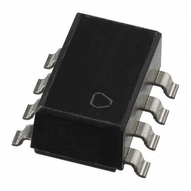
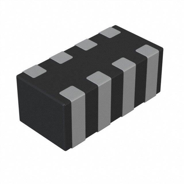
ICGOO电子元器件商城为您提供ZJYS51R5-4PT-01由TDK设计生产,在icgoo商城现货销售,并且可以通过原厂、代理商等渠道进行代购。 ZJYS51R5-4PT-01价格参考。TDKZJYS51R5-4PT-01封装/规格:共模扼流圈, 4 线 共模扼流圈 表面贴装 200 Ohms @ 100MHz 2A DCR 120 毫欧。您可以下载ZJYS51R5-4PT-01参考资料、Datasheet数据手册功能说明书,资料中有ZJYS51R5-4PT-01 详细功能的应用电路图电压和使用方法及教程。
TDK Corporation生产的共模扼流圈型号ZJYS51R5-4PT-01是一种高性能磁性元件,主要用于抑制差模和共模噪声,广泛应用于高频信号传输和电源系统中。以下是该型号的主要应用场景:

 1. 高速数据传输接口
   - ZJYS51R5-4PT-01适用于USB、HDMI、DisplayPort等高速数据传输接口的噪声滤波。它可以有效抑制高频共模噪声,确保信号完整性,同时减少对其他设备的电磁干扰(EMI)。

 2. 通信设备
   - 在路由器、交换机、基站等通信设备中,该共模扼流圈可用于保护电路免受外部电磁干扰的影响,并降低设备对外部环境的干扰,保证通信质量。

 3. 汽车电子系统
   - 在车载信息娱乐系统、导航系统和CAN总线中,ZJYS51R5-4PT-01可以抑制由高频信号引起的噪声,提高系统的稳定性和可靠性。

 4. 工业自动化设备
   - 用于工业控制中的PLC、伺服驱动器和传感器接口,能够有效抑制共模噪声,防止因噪声导致的误动作或信号失真。

 5. 消费电子产品
   - 在电视、音响、游戏机等消费电子产品中,该型号可作为EMI滤波器的一部分,减少高频噪声对音频和视频信号的影响,提升用户体验。

 6. 电源模块
   - 在开关电源(SMPS)、DC-DC转换器和AC-DC适配器中,ZJYS51R5-4PT-01可用于抑制输入/输出端的共模噪声,满足严格的EMC标准要求。

 特点总结:
- 高频率范围:适用于高频信号环境。
- 低插入损耗:在抑制噪声的同时,保持信号传输效率。
- 高共模阻抗:有效衰减共模噪声。
- 紧凑设计:适合空间受限的应用场景。

总之,ZJYS51R5-4PT-01凭借其优异的性能,成为各类电子设备中不可或缺的噪声抑制元件,特别适合需要高可靠性和低噪声的场景。
| 参数 | 数值 |
| 产品目录 | |
| DC电阻(DCR) | 120 毫欧最大 |
| 描述 | CHOKE COMMON MODE 4ARRAY 200 OHM |
| 产品分类 | |
| 品牌 | TDK Corporation |
| 数据手册 | |
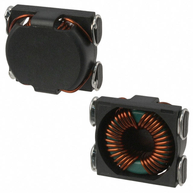
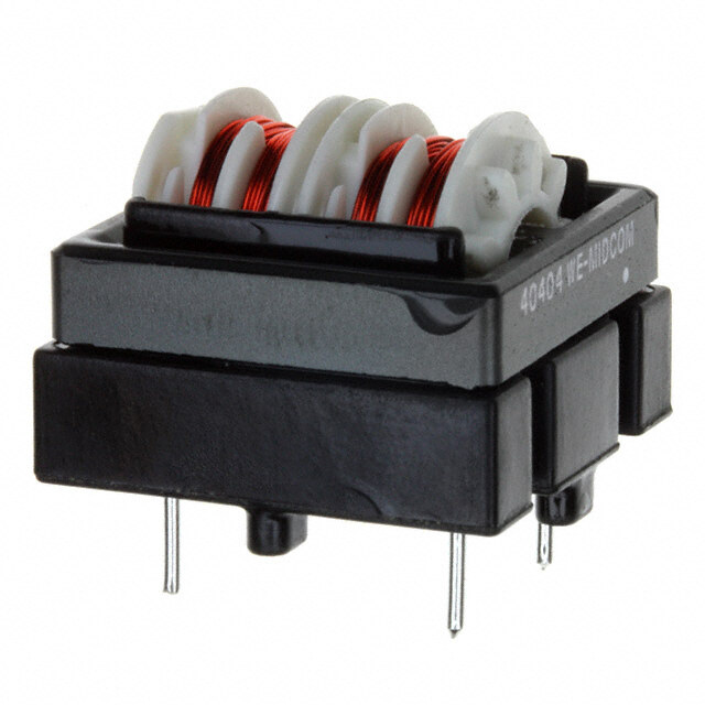
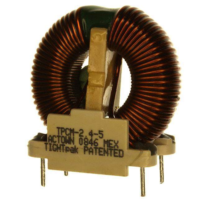
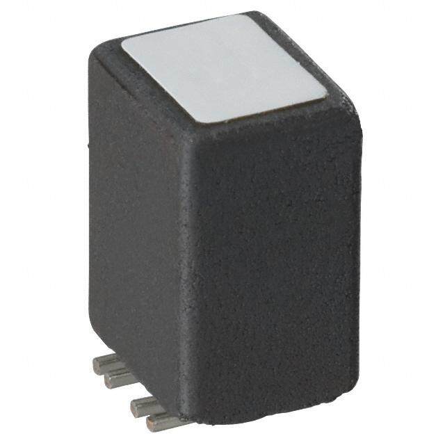
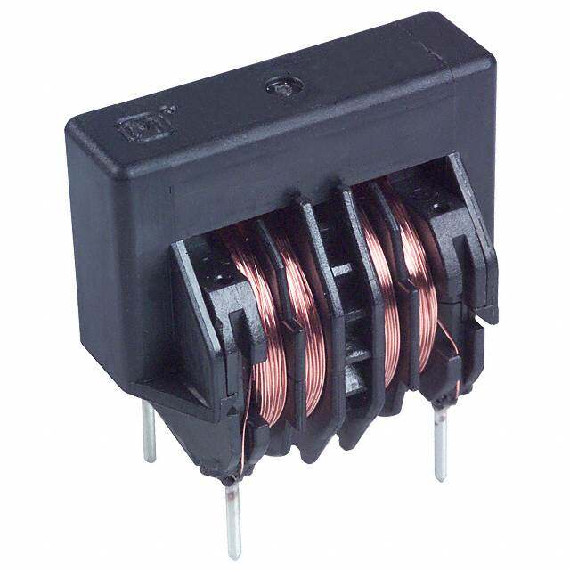
| 产品图片 |
|
| 产品型号 | ZJYS51R5-4PT-01 |
| rohs | 无铅 / 符合限制有害物质指令(RoHS)规范要求 |
| 产品系列 | ZJYS |
| 产品培训模块 | http://www.digikey.cn/PTM/IndividualPTM.page?site=cn&lang=zhs&ptm=7792 |
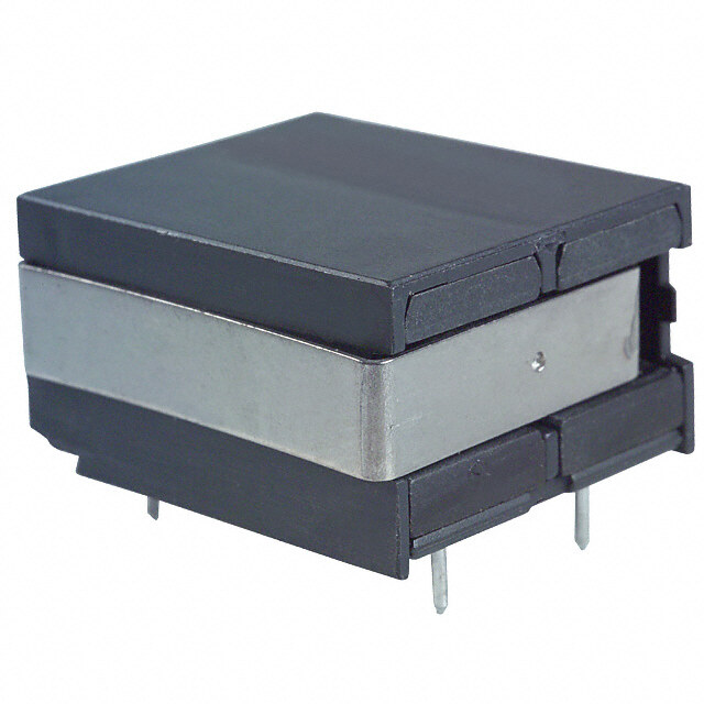
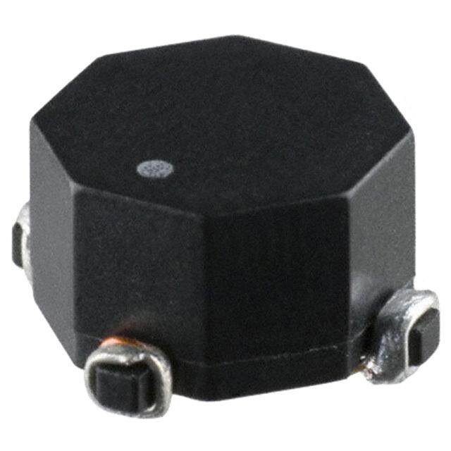
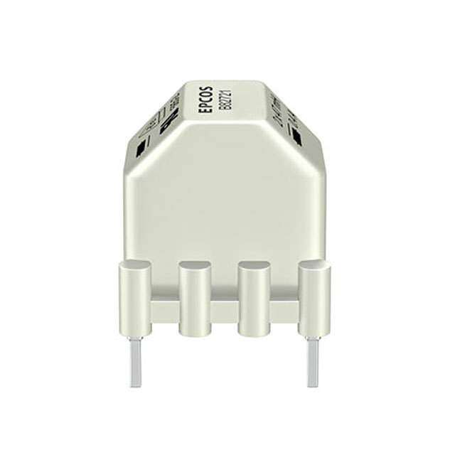
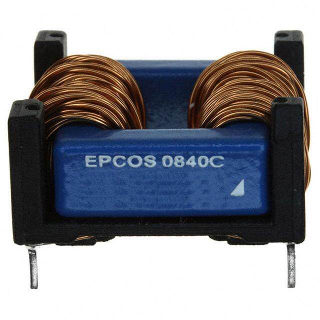
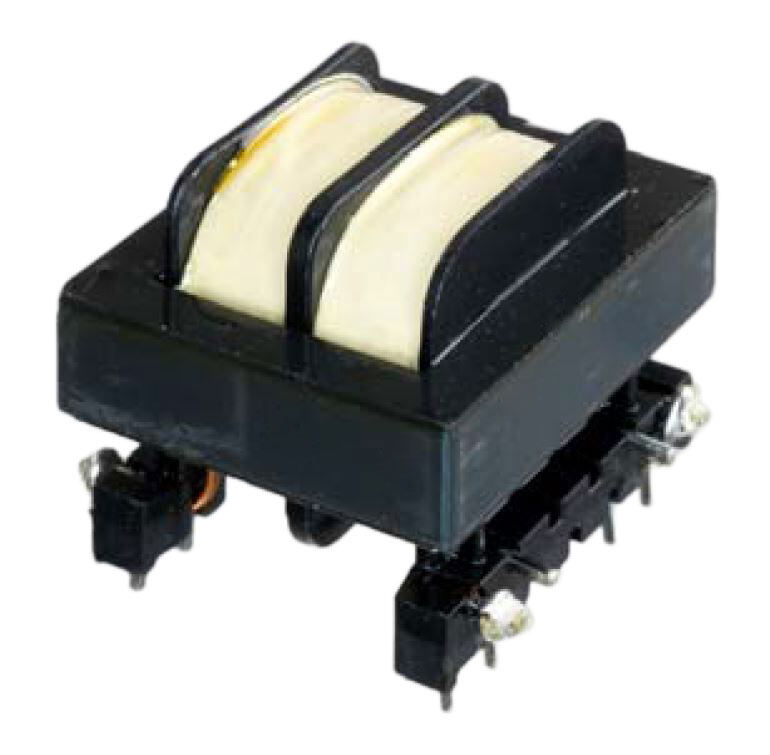
| 产品目录绘图 |
|
| 产品目录页面 | |
| 其它名称 | 445-2224-2 |
| 包装 | 带卷 (TR) |
| 大小/尺寸 | 0.413" 长 x 0.345" 宽(10.50mm x 9.00mm) |
| 安装类型 | 表面贴装 |
| 封装/外壳 | 垂直式,8 鸥翼形 |
| 工作温度 | -25°C ~ 85°C |
| 标准包装 | 1,000 |
| 滤波器类型 | 数据,信号线 |
| 电感 | - |
| 电流 | 2A |
| 线路数 | 4 |
| 阻抗 | 200 欧姆 |
| 高度(最大值) | 0.200"(5.08mm) |


- 商务部:美国ITC正式对集成电路等产品启动337调查
- 曝三星4nm工艺存在良率问题 高通将骁龙8 Gen1或转产台积电
- 太阳诱电将投资9.5亿元在常州建新厂生产MLCC 预计2023年完工
- 英特尔发布欧洲新工厂建设计划 深化IDM 2.0 战略
- 台积电先进制程称霸业界 有大客户加持明年业绩稳了
- 达到5530亿美元!SIA预计今年全球半导体销售额将创下新高
- 英特尔拟将自动驾驶子公司Mobileye上市 估值或超500亿美元
- 三星加码芯片和SET,合并消费电子和移动部门,撤换高东真等 CEO
- 三星电子宣布重大人事变动 还合并消费电子和移动部门
- 海关总署:前11个月进口集成电路产品价值2.52万亿元 增长14.8%
PDF Datasheet 数据手册内容提取
E M C C o m p o n e n t s December 2015 Common Mode Filters For signal line ZJYS51 Series ZJYS51R5 Type Caution The products in this catalog will be or have been stopped production Discontinue Issue Date Nov.4, 2015 Last Purchase Order Date Sep.29, 2017 Last Shipment Date Mar.30, 2018 Please refer to our Web site about replacement information.
(2/9) E M C C o m p o n e n t s REMINDERS FOR USING THESE PRODUCTS Before using these products, be sure to request the delivery specifications. n SAFETY REMINDERS e Please pay sufficient attention to the warnings for safe designing when using these products. e b REMINDERS e The storage period is less than 12 months. Be sure to follow the storage conditions (Temperature: 5 to 40°C, Humidity: 10 to 75% RH v or less). If the storage period elapses, the soldering of the terminal electrodes may deteriorate. a n Do not use or store in locations where there are conditions such as gas corrosion (salt, acid, alkali, etc.). h o Before soldering, be sure to preheat components. The preheating temperature should be set so that the temperature difference between the solder temperature and chip temperature r i does not exceed 150°C. o t c Soldering corrections after mounting should be within the range of the conditions determined in the specifications. If overheated, a short circuit, performance deterioration, or lifespan shoretening may ocucur. When embedding a printed circuit board where a chip is mounted to a set, be sure that residual stress is not given to the chip due to b d the overall distortion of the printed circuit board and partial distortion such as at screw tightening portions. o Self heating (temperature increase) occurs when the power is turned ON, so the tolerance should be sufficient for the set thermal l design. l r Carefully lay out the coil for the circuit board design of thei non-magneticp shield type. w A malfunction may occur due to magnetic interference. Use a wrist band to discharge static electricity in your body througdh the grounding wire. Do not expose the products to magnets or magnsetic fields. e t Do not use for a purpose outside of the contents regulated in the delivery specifications. p c The products listed on this catalog are intended for use in general electronic equipment (AV equipment, telecommunications p equipment, home appliances, amusemeunt equipment, computer equipment, personal equipment, office equipment, measurement equipment, industrial robots) under da normal operaotion and use condition. The products are not designed or warranted to meet the requirements of the applications listed below, whose performance and/or quality require a more stringento level of safety tor reliability, or whose failure, malfunction or trouble could cause serious damage to society, person or property. s If you intend to use the prodructs in the applications listed below or if you have special requirements exceeding the range or conditions set forth in the each cataplog, please contact us. (1) Aerospace/Aviation equipment (8) Public information-processing equipment e (2) Transportation equipment (cars, electric trains, ships, etc.) (9) Military equipment (3) Medical equhipment (10) Electric heating apparatus, burning equipment (4) Power-generation control equipment (11) Disaster prevention/crime prevention equipment T (5) Atomic energy-related equipment (12) Safety equipment (6) Seabed equipment (13) Other applications that are not considered general-purpose (7) Transportation control equipment applications When designing your equipment even for general-purpose applications, you are kindly requested to take into consideration securing protection circuit/device or providing backup circuits in your equipment. 20151221 / cmf_commercial_signal_zjys51r5_en.fm
(3/9) E M C C o m p o n e n t s Common Mode Filters Product compatible with RoHS directive For signal line Overview of ZJYS51R5 Type n e e FEATURES b Optimal common mode filter for removing noise without straining the transmission signal and for tra nsmitting high-quality signals. Optimal countermeasure for common mode noise induced during data transmission for digital siegnal processing such as in PCs and telephones. v SMD type structure makes it optimal for surface mounting. Up to 2A current is allowable, so it can be used as a noise countermeasure for power supaply lines. n h APPLICATION o PCs, telephones, LANs, ISDNs, digital PBXs, game machines, CTVs, CD-ROMs, 8mrm video cassiette recorders, etc. o t c PART NUMBER CONSTRUCTION e u ZJYS51R5 - 2P T - 01 b d Product internal Series • Type name code Packaging style Internaol code 2P l 01 2PB T ø330mml reel r 2PL i p 4P w M4PA d OPERATING TEMPERATURE RANGEs, PACKAGeE QUANTITY, PRODUCT WEIGHT t Temperature range p Package quantity Individual weight Operating c Storage Type temperature temperature(cid:2) p (°C) u (°C) (pieces/reel) (g) ZJYS51R5-2PT-01 –25 to +85 –25 to +85 1,500 0.4 ZJYS51R5-2PBT-01 –25 to +d85 –o25 to +85 1,500 0.4 ZJYS51R5-2PLT-01 –25 to +85 –25 to +85 1,500 0.4 ZJYS51R5-4PT-01 –25o to +85 t–25 to +85 1,000 0.8 ZJYS51R5-M4PAT-01 –25 to +85 s–25 to +85 1,000 0.8 (cid:2)(cid:3)The Storage temperature range irs for after the circuit board is mounted. p e h T RoHS Directive Compliant Product: See the following for more details related to RoHS Directive compliant products. http://product.tdk.com/en/environment/rohs/ Halogen-free: Indicates that Cl content is less than 900ppm, Br content is less than 900ppm, and that the total Cl and Br content is less than 1500ppm. Please be sure to request delivery specifications that provide further details on the features and specifications of the products for proper and safe use. Please note that the contents may change without any prior notice due to reasons such as upgrading. 20151221 / cmf_commercial_signal_zjys51r5_en.fm
(4/9) E M C C o m p o n e n t s ZJYS51R5 Type RECOMMENDED REFLOW PROFILE n Preheating Soldering Natural cooling e Peak e T4 b e ur T3 T3 at er e p m e T T2 v T: t3 a T1 n h t1 t2 o r i o t t: Time c e u Preheating Soldering Peak b d Temp. Time Temp. Time Temp. Time T1 T2 t1 T3 t2 T4 t3 o 150°C 180°C 60 to 120s 230°C 10 to 30s 245°C 5s l l r i p w d s e t p c p u d o o t s r p e h T Please be sure to request delivery specifications that provide further details on the features and specifications of the products for proper and safe use. Please note that the contents may change without any prior notice due to reasons such as upgrading. 20151221 / cmf_commercial_signal_zjys51r5_en.fm
(5/9) E M C C o m p o n e n t s ZJYS51R5-2PT-01, -2PBT-01, -2PLT-01 SHAPE & DIMENSIONS 5.5max. n 4 3 e Marking: TDK e Marking: Product internal code b Marking: Production date code e 9±0.5 1 2 6.86max. v a max. max. h n 5.08 4.57 0.25 o 2.54±0.25 (0.6) r i 1.3 o t c Dimensions in mm e u b d o l RECOMMENDED LAND PATTERN l CIRrCUIT DIAGRAM i p 4 3 w d 6.79.9 s e 1.8 t p 1 2 c • No polarity 6 1. p u 2.54 Dimensions in mm d o o t s r p e h T Please be sure to request delivery specifications that provide further details on the features and specifications of the products for proper and safe use. Please note that the contents may change without any prior notice due to reasons such as upgrading. 20151221 / cmf_commercial_signal_zjys51r5_en.fm
(6/9) E M C C o m p o n e n t s ZJYS51R5-2PT-01, -2PBT-01, -2PLT-01 ELECTRICAL CHARACTERISTICS CHARACTERISTICS SPECIFICATION TABLE n Part No. ZJYS51R5-2PT-01 ZJYS51R5-2PBT-01(cid:2)1 ZJYS51R5-2PLT-01(cid:2)2 Rated voltage Edc(V) 50 50 50 e Rated current (A) 2 2 2 Test voltage Edc(V) e 125 125 250 [Between terminals for 5s] Insulation resistance (M(cid:4)) b 100 min. 100 min. 100 min. [Between terminals at DC.50V for 1min] DC resistance ((cid:4)) [1 line] 0.12 max. 0.12 max. 0.10 max. Impedance ((cid:4))[+5 to +35°C] 200 min.[20 to 300MHz] 300 min.[6 to 20MHz] e 100 min.[20 to 100MHz] ○Measurement equipment v Measurement item Product No. Manufacturer Common mode impedance 4991A Agilent Technologies a DC resistance 4338A Agilent Technologies n h Insulation resistance 4339A Agilent Technologies o * Equivalent measurement equipment may be used. r i o t c e u b d o l IMPEDANCE VS. FREQUENCY CHARACTERISTICS (FORl 1 ELEMENT)r i p 10000 w d 2PB Commosn mode e2PT Common mode 1000 t p Ω) c (ce u 2PL Compmon mode n 100 a ed d o p m I o t s2PL Differential mode 10 r 2PT Differential mode p 2PB Differential mode 1 e 1 3 10 30 100 300 1000 Frequency (MHz) h ○Measurement equipment T Product No. Manufacturer 4991A Agilent Technologies * Equivalent measurement equipment may be used. Please be sure to request delivery specifications that provide further details on the features and specifications of the products for proper and safe use. Please note that the contents may change without any prior notice due to reasons such as upgrading. 20151221 / cmf_commercial_signal_zjys51r5_en.fm
(7/9) E M C C o m p o n e n t s ZJYS51R5-4PT-01, -M4PAT-01 SHAPE & DIMENSIONS 10.5max. n 8 7 6 5 e Marking: Production date code e Marking: Product internal code b 1 2 3 4 9±0.5 e 6.86max. v 5.08max. 4.57max. 0.25 ha n o 2.54±0.25 (0.6) 1.3 r i o t c Dimensions in mm e u b d o l l r i p RECOMMENDED LAND PATTERN CIRCUIT DIAGRAM w ZJY S51R5-4PT-01 ZJYS51R5-M4PAT-01 d 8 7 6 5 8 7 6 5 s e 6.79.9 t p 1.8 c p u 6 1. 1 2 3 4 1 2 3 4 2.54 2.54 2.54 d o • No polarity • No polarity Dimensions in mmo t s r p e h T Please be sure to request delivery specifications that provide further details on the features and specifications of the products for proper and safe use. Please note that the contents may change without any prior notice due to reasons such as upgrading. 20151221 / cmf_commercial_signal_zjys51r5_en.fm
(8/9) E M C C o m p o n e n t s ZJYS51R5-4PT-01, -M4PAT-01 ELECTRICAL CHARACTERISTICS CHARACTERISTICS SPECIFICATION TABLE n Part No. ZJYS51R5-4PT-01 ZJYS51R5-M4PAT-01 Rated voltage Edc(V) 50 50 e Rated current (A) 2 0.5 Test voltage Edc(V) e 125 125 [Between terminals for 5s] Insulation resistance (M(cid:4)) b 100 min. 100 min. [Between terminals at DC.50V for 1min] DC resistance ((cid:4)) [1 line] 0.12 max. 0.25 max. Impedance ((cid:4))[+5 to +35°C] 200 min.[20 to 300MHz] 200 min.[20 to 300MHz] e ○Measurement equipment v Measurement item Product No. Manufacturer Common mode impedance 4991A Agilent Technologies a DC resistance 4338A Agilent Technologies n h Insulation resistance 4339A Agilent Technologies o * Equivalent measurement equipment may be used. r i o t c e u b d o l IMPEDANCE VS. FREQUENCY CHARACTERISTICS (FORl 1 ELEMENT)r i p 10000 w d 1000 s e4PT Common mode M4PA Common mode t p Ω) c (e p c u n 100 a ed d o p m I o t s 10 r 4PT Differential mode p M4PA Differential mode 1 e 1 3 10 30 100 300 1000 Frequency (MHz) h ○Measurement equipment T Product No. Manufacturer 4991A Agilent Technologies * Equivalent measurement equipment may be used. Please be sure to request delivery specifications that provide further details on the features and specifications of the products for proper and safe use. Please note that the contents may change without any prior notice due to reasons such as upgrading. 20151221 / cmf_commercial_signal_zjys51r5_en.fm
(9/9) E M C C o m p o n e n t s ZJYS51R5 Type PACKAGING STYLE REEL DIMENSIONS n 2.0±0.5 E e Type A W1 W2 N E ZJYS51R5-2 ø330±4/–2 16.4+e2/–0 22.4max. ø100±1 2 typ. ZJYS51R5-4P,M4PA ø330±4/–2 16.4+2/–0 22.4max. ø100±1 2 typ. b N e v 1.0 a n h ø13.0±0.5 W1 o ø21.0±0.8 W2 r i A o t c Dimensions in mm e u b d TAPE DIMENSIONS o øD0 P2 P0 t E l l r i p F w W B d A P1 s K e t p c Dimensions in mm Type A B u øD0 pE F P0 P1 P2 W K t ZJYS51R5-2 5.8±0.1 9.8±0.1 1.5+0.1/0 1.75±0.1 7.5±0.1 4.0±0.1 8.0±0.1 2.0±0.1 16.0±0.3 5.2 0.4 ZJYS51R5-4P,M4PA 9.8±0.1 10.5d±0.1 1.5+0.1/o0 1.75±0.1 7.5±0.1 4.0±0.1 12.0±0.1 2.0±0.1 16.0±0.3 5.2 0.4 o t 500 to 560 s 160min. Taping r 240min. p Drawing directione h T Please be sure to request delivery specifications that provide further details on the features and specifications of the products for proper and safe use. Please note that the contents may change without any prior notice due to reasons such as upgrading. 20151221 / cmf_commercial_signal_zjys51r5_en.fm