ICGOO在线商城 > Y92F-76

 Datasheet下载
- 型号: Y92F-76
- 制造商: Omron Electronics LLC
- 库位|库存: xxxx|xxxx
- 要求:
| 数量阶梯 | 香港交货 | 国内含税 |
| +xxxx | $xxxx | ¥xxxx |
查看当月历史价格
查看今年历史价格
Y92F-76产品简介:
ICGOO电子元器件商城为您提供Y92F-76由Omron Electronics LLC设计生产,在icgoo商城现货销售,并且可以通过原厂、代理商等渠道进行代购。 提供Y92F-76价格参考以及Omron Electronics LLCY92F-76封装/规格参数等产品信息。 你可以下载Y92F-76参考资料、Datasheet数据手册功能说明书, 资料中有Y92F-76详细功能的应用电路图电压和使用方法及教程。
| 参数 | 数值 |
| 产品目录 | 工业控制装置,量表机电产品 |
| 描述 | PANEL ADAPTER VERT FOR H7 SER安装硬件 COUNTER PNL ADAPTER |
| 产品分类 | |
| 品牌 | Omron Automation and Safety |
| 产品手册 | |
| 产品图片 |
|
| rohs | 符合RoHS无铅 / 符合限制有害物质指令(RoHS)规范要求 |
| 产品系列 | 安装硬件,Omron Automation and Safety Y92F-76H7E |
| 数据手册 | |
| 产品型号 | Y92F-76 |
| 产品 | Mounting Brackets |
| 产品目录绘图 |
|
| 产品目录页面 | |
| 产品种类 | 安装硬件 |
| 其它名称 | Y92F76 |
| 包括 | - |
| 商标 | Omron Automation and Safety |
| 安装孔大小 | 4.5 in |
| 宽度 | 52.5 in |
| 工厂包装数量 | 1 |
| 标准包装 | 1 |
| 类型 | Panel |
| 系列 | H7E |
| 规格 | 面板安装,矩形 52.5mm x 27.5mm 外形尺寸 |
| 配件类型 | 适配器片 |
| 配套使用产品/相关产品 | H7E 系列 |
| 配用 | /product-detail/zh/H7EC-N-B-601/H7EC-N-B-601-ND/2669551/product-detail/zh/H7EC-N/H7EC-N-ND/2669550/product-detail/zh/H7ET-NV-300/H7ET-NV-300-ND/1812964/product-detail/zh/H7ET-NV1/Z3005-ND/1812962/product-detail/zh/H7ET-NV/Z3004-ND/1812961/product-detail/zh/H7ET-NFV1/H7ET-NFV1-ND/1812959/product-detail/zh/H7ET-NFV/H7ET-NFV-ND/1812958/product-detail/zh/H7ET-N1/Z3489-ND/1812957/product-detail/zh/H7ET-N/Z3003-ND/1812956/product-detail/zh/H7ER-NV1-H/H7ER-NV1-H-ND/1812954/product-detail/zh/H7ER-NV1/H7ER-NV1-ND/1812953/product-detail/zh/H7ER-NV/Z3007-ND/1812952/product-detail/zh/H7ER-N/Z3006-ND/1812951/product-detail/zh/H7EC-NV-H/H7EC-NV-H-ND/1812950/product-detail/zh/H7EC-NV/Z3008-ND/1812949/product-detail/zh/H7EC-NP/Z3009-ND/1812948/product-detail/zh/H7EC-NFV/H7EC-NFV-ND/1812946/product-detail/zh/H7ET-NV-BH/Z2744-ND/1642239/product-detail/zh/H7ER-NV1-B/Z2742-ND/1642231/product-detail/zh/H7ER-NV1-BH/Z2743-ND/1642230/product-detail/zh/H7ET-NV1-BH/Z1150-ND/408049/product-detail/zh/H7ET-NV1-B/Z1149-ND/408048/product-detail/zh/H7ER-NV-BH/Z1147-ND/408047/product-detail/zh/H7ER-NV-B/Z1146-ND/408046/product-detail/zh/H7ER-N-B/Z1145-ND/408045/product-detail/zh/H7EC-NV-BH/Z1144-ND/408044/product-detail/zh/H7ET-NFV-B/Z875-ND/206355/product-detail/zh/H7ET-NFV1-B/Z874-ND/206354/product-detail/zh/H7ET-N1-B/Z873-ND/206353/product-detail/zh/H7ET-NV-B/Z872-ND/206352/product-detail/zh/H7ET-N-B/Z870-ND/206350/product-detail/zh/H7EC-NFV-B/Z867-ND/206347/product-detail/zh/H7EC-NV-B/Z865-ND/206345/product-detail/zh/H7EC-N-B/Z861-ND/206340 |
| 长度 | 27.5 in |
| 颜色 | Light Gray |


- 商务部:美国ITC正式对集成电路等产品启动337调查
- 曝三星4nm工艺存在良率问题 高通将骁龙8 Gen1或转产台积电
- 太阳诱电将投资9.5亿元在常州建新厂生产MLCC 预计2023年完工
- 英特尔发布欧洲新工厂建设计划 深化IDM 2.0 战略
- 台积电先进制程称霸业界 有大客户加持明年业绩稳了
- 达到5530亿美元!SIA预计今年全球半导体销售额将创下新高
- 英特尔拟将自动驾驶子公司Mobileye上市 估值或超500亿美元
- 三星加码芯片和SET,合并消费电子和移动部门,撤换高东真等 CEO
- 三星电子宣布重大人事变动 还合并消费电子和移动部门
- 海关总署:前11个月进口集成电路产品价值2.52万亿元 增长14.8%


PDF Datasheet 数据手册内容提取
Self-powered Totalizer New H7E CSM_H7E_-N_DS_E_9_2 Compact Economical Totalizer with High Visibility Available with Backlit LCD Display •Large display with 8.6-mm character height. •Includes new models with backlight for improved visibility in dimly lit places. (Requires 24-VDC power supply.) •Black and light-gray cases now available. •PNP/NPN universal DC voltage input types now available. •Battery is replaceable for Totalizer reuse and conservation of the environment. •Key-protect switch to prevent faulty reset key operation. •Dual operation mode. •Front face compatible with NEMA4/IP66. •Short body, all models have a depth of 48.5 mm. •Finger protection terminal block conforms to VDE0106, Part100. •Conforms to UL, CSA, and CE marking. Conforms to EN61010-1 (pollution degree 2/overvoltage category III.) •Conforms to EMC standards and EN61326, thus allowing use in residential, commercial and light- and heavy-industry environ- ments. •Six-language instruction manual provided. •PCB-mounting models available. (Requires 3-V power supply.) ■ Broad Line-up of the New H7E Series New H7E New H7EC New H7ET New H7ER New H7E@-N@P Total Counter Time Counter Tachometer PCB-mounting Counter (cid:129) 8-digit (cid:129) 999999.9h/ (cid:129) 1,000 s-1 with (cid:129) Total Counter (8-digit) 3999d23.9h (cid:129) Time Counter (999999.9h) 1 pulse/rev. encoder (cid:129) 999h59min59s/ (cid:129) 1,000.0 s-1 with 9999h59.9min 10 pulse/rev. encoder (cid:129) 1,000 min-1 with 60 pulse/rev. encoder (cid:129) 10,000 min-1 with 60 pulse/rev. encoder (cid:129) 1,000.0 min-1 with 600 pulse/rev. encoder Contents Self-powered Totalizers H7EC..................................................................................................................... 2 H7ET..................................................................................................................... 9 H7ER..................................................................................................................... 16 H7E@-N@P........................................................................................................... 22 Common to All Totalizers Accessories........................................................................................................... 27 Precautions........................................................................................................... 29 1
Self-powered Total Counter New H7EC •Eight-digits, counting range 0 to 99999999. (cid:129)Dual input speed: 30 Hz ←→ 1 kHz (except for AC/DC multi- voltage input models) For the most recent information on models that have been certified for safety standards, refer to your OMRON website. Model Number Structure ■ Model Number Legend Note:Some configurations are not available. H7EC - N - 1 2 3 1. Count Input 3. Display None: No-voltage input None: 7-segment LCD without backlight V: PNP/NPN universal DC voltage input H: 7-segment LCD with backlight FV: AC/DC multi-voltage input 2. Case Color None: Light gray B: Black Note: Estimates can be provided for coatings and other specifications that are not given in the datasheet. Ask your OMRON representative for details. Ordering Information ■ Total Counters Count input Max. counting speed Display Model Light-gray body Black body PNP/NPN universal DC 30 Hz ←→ 1 kHz 7-segment LCD with H7EC-NV-H H7EC-NV-BH voltage input (switchable) backlight (4.5 to 30 VDC) 7-segment LCD H7EC-NV H7EC-NV-B AC/DC multi-voltage input 20 Hz 7-segment LCD H7EC-NFV H7EC-NFV-B (24 to 240 VAC/VDC) No-voltage 30 Hz ←→ 1 kHz 7-segment LCD H7EC-N H7EC-N-B (switchable) ■ Accessories (Order Separately) Name Model Compact Flush Mounting Bracket Y92F-35 Flush Mounting Bracket (See note 1) Y92F-34 Wire-wrap Terminal (set of two Terminals) Y92S-37 Lithium Battery (See note 2) Y92S-36 Waterproof Packing (See note 1) Y92S-32 Note:1. Provided with H7EC. (Order additional Brackets separately as required.) 2. Built into H7EC. Order replacements using the above model number before the service life expires. 2
New H7EC Specifications ■ General Item H7EC-NV-@ H7EC-NFV-@ H7EC-N-@ H7EC-NV-@H Operating mode Up type Mounting method Flush mounting External connections Screw terminals, optional Wire-wrap Terminals (see note 1) Reset External/Manual reset Number of digits 8 Count input PNP/NPN universal DC voltage in- AC/DC multi-voltage input No-voltage input put Display 7-segment LCD with or without backlight, zero suppression (character height: 8.6 mm) (see note 2) Max. counting speed 30 Hz/1 kHz 20 Hz 30 Hz/1 kHz Case color Light gray or black (-B models) Attachment Waterproof packing, Y92F-34 Flush Mounting Bracket Approved standard UL863, CSA C22.2 No.14, Lloyds Conforms to EN61010-1/IEC61010-1 (Pollution degree2/overvoltage category III) Conforms to VDE0106/P100 Note:1. Separately ordered Wire-wrap Terminals (Y92S-37) are required. 2. Only PNP/NPN universal DC voltage input models (-H models) have a backlight. ■ Ratings Item H7EC-NV-@ H7EC-NFV-@ H7EC-N-@ H7EC-NV-@H Supply voltage Backlight model: 24 VDC (0.3 W max.) Not required (powered by built-in battery) (only for backlight) No-backlight model: Not required (powered by built-in battery) Count input High (logic) level: 4.5 to 30VDC High (logic) level: 24 to 240VAC/VDC, No voltage input Low (logic) level: 0 to 2 VDC 50/60 Hz Maximum short-circuit impedance: (Input impedance: Approx. 4.7kΩ) Low (logic) level: 0 to 2.4VAC/VDC, 50/ 10kΩ max. 60 Hz Short-circuit residual voltage: 0.5 V max. Minimum open impedance: 750kΩ min. Reset input No voltage input Maximum short-circuit impedance: 10kΩ max. Short-circuit residual voltage: 0.5 V max. Minimum open impedance: 750kΩ min. Max. counting 30 Hz or 1 KHz 20 Hz 30 Hz or 1 KHz speed (seenote) (Switchable with switch) (Switchable with switch) Minimum signal 20 Hz: 25 ms width 30 Hz: 16.7 ms 1 KHz: 0.5 ms Reset system External reset and manual reset: Minimum signal width of 20 ms Terminal screw 0.98 N·m max. tightening torque Ambient tempera- Operating:–10°C to 55°C (with no condensation or icing) ture Storage: –25°C to 65°C (with no condensation or icing) Ambient humidity Operating 25% to 85% Note:ON/OFF ratio 1:1 3
New H7EC ■ Characteristics Item H7EC-NV-@ H7EC-NFV-@ H7EC-N-@ H7EC-NV-@H Insulation resistance 100 MΩ min. (at 500 VDC) between 100 MΩ min. (at 500 VDC) between 100 MΩ min. (at 500 VDC) between current-carrying metal parts and ex- current-carrying metal parts and ex- current-carrying metal parts and ex- posed non-current-carrying metal posed non-current-carrying metal parts posed non-current-carrying metal parts parts, and between the backlight power and between count input terminals and supply terminal and count input termi- reset terminals nals/reset terminals for backlight mod- els Dielectric strength 1,000 VAC, 50/60 Hz for 1 min between 3,700 VAC, 50/60 Hz for 1 min between 1,000 VAC, 50/60 Hz for 1 min between current-carrying metal parts and ex- current-carrying metal parts and ex- current-carrying metal parts and ex- posed non-current-carrying metal parts posed non-current-carrying metal parts posed non-current-carrying metal parts and between the backlight power sup- 2,200 VAC, 50/60 Hz for 1 min between ply terminal and count input terminals/ reset terminals and exposed non-cur- reset terminals for backlight models rent-carrying metal parts and between count input terminals and reset termi- nals Impulse withstand 4.5 kV between current-carrying termi- 4.5 kV between current-carrying termi- 4.5 kV between current-carrying termi- voltage nal and exposed non-current-carrying nal and exposed non-current-carrying nal and exposed non-current-carrying metal parts metal parts metal parts 3 kV between input terminals and reset terminals Noise immunity Square-wave noise generated by noise simulator (pulse width: 100 ns/1 μs, 1-ns rise) ±600 V (Between count input terminals/ ±1.5 kV (Between count input termi- ±500 V (Between count input terminals/ Between reset terminals) nals) Between reset terminals) ±480 V (Between the backlight power ±500 V (Between reset terminals) supply terminals for backlight models) Static immunity ±8 kV (malfunction) Vibration resistance Malfunction:0.15-mm single amplitude at 10 to 55 Hz for 10 min each in 3 directions Destruction:0.375-mm single amplitude at 10 to 55 Hz for 2 hrs each in 3 directions Shock resistance Malfunction:200 m/s2 3 times each in 6 directions Destruction:300 m/s2 3 times each in 6 directions EMC (EMI) EN61326-1 (See note 1.) Emission Enclosure: EN55011 Group 1 class B (EMS) EN61326-1 (See note 1.) Immunity ESD: EN61000-4-2: 4 kV contact discharge (level 2) 8 kV air discharge (level 3) Immunity RF-interference from AM Radio Waves: EN61000-4-3: 10 V/m (80 MHz to 1 GHz) (level 3) Immunity RF-interference from Pulse-modulated Radio Waves: EN61000-4-3: 10 V/m (900 MHz ± 5 MHz) (level 3) Immunity Conducted Disturbance: EN61000-4-6: 10 V (0.15 to 80 MHz) (level 3) Immunity Burst: EN61000-4-4: 2 kV power line (level 3) 2 kV I/O signal line (level 4) Degree of protection Front panel: IP66, NEMA4 Terminal block:IP20 Weight (see note 2.) No-backlight model: Approx. 60 g Approx. 60 g Approx. 60 g Backlight model: Approx. 65 g Note:1. Industrial electromagnetic environment (EN/IEC 61326-1 Table 2) 2. Weight includes waterproof packing and flush mounting bracket. ■ Reference Value Item Value Note Battery life 7 years min. with continuous input at 25°C The battery life is calculated according to the conditions in the left column and (lithium battery) therefore is not a guaranteed value. Use these value as reference for mainte- nance or replacement. 4
New H7EC Connections ■ Terminal Arrangement Bottom view: View of the Total Counter rotated horizontally 180° Backlight Model No-backlight Model Backlight 24 VDC Count Reset Count Reset input input input input ■ Connections H7EC Total Counter PNP/NPN Universal DC Voltage Input Model With Backlight 1. Contact Input (Input by a Relay or Switch Contact) 2. Solid-state Input Open collector of a Open collector of a Relay Relay PNP transistor Backlight PNP transistor Backlight 24 VDC 24 VDC Input Reset Input Reset or Switch or Switch or Open collector of an or Open collector of an NPN transistor NPN transistor Note:1. Terminals 2 and 4 (input circuit and reset circuit) are func- tionally isolated. 2. Select input transistors according to the following: Dielectric strength of the collector ≥ 50 V Leakage current < 100 µA 5
New H7EC PNP/NPN Universal DC Voltage Input Model Without Backlight No-voltage Input Model 1. Contact Input (Input by a Relay or Switch Contact) 1. Contact Input (Input by a Relay or Switch Contact) Relay Relay Relay Relay Input Reset Input Reset Terminals 2 and 4 are internally connected. or Switch or Switch or Switch or Switch Note: Use Relays and Switches that have high contact 2. Solid-state Input reliability because the current flowing from terminals Open collector of a Open collector of a 1 or 3 is small. It is recommended that OMRON's PNP transistor PNP transistor G3TA-IA/ID be used as the SSR. Input Reset 2. Solid-state Input (Open Collector Input of an NPN Transistor) Open collector of an Open collector of an NPN transistor Input Reset NPN transistor or Open collector of an or Open collector of an Terminals 2 and 4 are NPN transistor NPN transistor internally connected. or Switch Note: 1. Residual voltage in the output section of Proximity Sensors or Photoelectric Sensors becomes less than 0.5 V because the current flowing from terminals 1 or 3 is small thus allowing easy connection. 2. Select input transistors according to the following: Note: 1. Terminals 2 and 4 (input circuit and reset circuit) are Dielectric strength of the collector ≥ 50 V functionally isolated. Leakage current < 1 µA 2. Select input transistors according to the following: Dielectric strength of the collector ≥ 50 V Leakage current < 100 µA AC/DC Multi-voltage Input Model Relay Relay Input Reset or Switch or Switch or Open collector of an NPN transistor Note: Select input transistors according to the following: Dielectric strength of the collector ≥ 50 V Leakage current < 1 µA 6
New H7EC Operation ■ Operating Modes H7EC Total Counter Incrementing Operation (Up) Reset Count input Full-scale (Full-scale −1) Counting display values Nomenclature Front view Reset Key H7EC Reset the count value. Not operable under key-protect. Counting speed switch Key-protect Switch For all models except for H7EC-NFV-@. The Reset Key is not operable while the If the counting speed setting is changed, key-protect switch is set to ON. the present value will not be held and so press the Reset Key on the front panel. Setting Key-protect (see note) Setting Counting speed (see note) Bottom view Front panel OFF Front panel Concave side (default setting) Concave 30 Hz side (default setting) Concave ON side Concave 1 kHz side Terminal block Terminal block Note:1. Perform switch setting before mounting to a control panel. 2. If the counting speed setting is changed, the present value will not be held. Press the Reset Key on the front panel. 3. Key protection is used to prohibit operating the Reset Key. The reset input terminals will still be functional. 7
New H7EC Dimensions Note:All units are in millimeters unless otherwise indicated. H7EC-N M3.5 terminal screw Panel Cutout Separate mounting 40 min. 45+00.5 22.2+00.5 Dimensions with Y92F-34 Flush Mounting Bracket Dense mounting (48 Units − 2.5)+10.0 22.2+00.5 Waterproofing is not possible for dense mounting • When mounting, insert the Counter into the cutout, insert the adapter from the back and push in the Counter while making the gap between the front panel and the cutout panel as small as possible. Use screws to secure the Counter. If waterproofing is desired, insert the waterproof packing. • When several Counters are installed, ensure that the ambient temperature will not exceed specifications. • The appropriate thickness of the panel is 1 to 5 mm. Note:A Compact Flush Mounting Bracket (Y92F-35) can also be used. Refer to Accessories for details. 8
Self-powered Time Counter New H7ET •Seven digits, time range 0 to 3999d23.9h. (cid:129)Dual time range: 999999.9 ←→ 3999d23.9h or 999h59m59s ←→ 9999h59.9m For the most recent information on models that have been certified for safety standards, refer to your OMRON website. Model Number Structure ■ Model Number Legend Note:Some configurations are not available. H7ET - N - 1 2 3 4 1. Count Input 3. Case Color None: No-voltage input None: Light gray V: PNP/NPN universal DC voltage input B: Black FV: AC/DC multi-voltage input 4. Display 2. Time Range None: 7-segment LCD without backlight None: 999999.9h/3999d23.9h H: 7-segment LCD with backlight 1: 999h59m59s/9999h59.9m Note:Estimates can be provided for coatings and other specifications that are not given in the datasheet. Ask your OMRON representative for details. Ordering Information ■ Time Counters Timer input Display Time range 999999.9h ←→ 3999d23.9h 999h59min59s ←→ 9999h59.9min (switchable) (switchable) Light-gray body Black body Light-gray body Black body PNP/NPN universal DC volt- 7-segment LCD with back- H7ET-NV-H H7ET-NV-BH H7ET-NV1-H H7ET-NV1-BH age input light (4.5 to 30 VDC) 7-segment LCD H7ET-NV H7ET-NV-B H7ET-NV1 H7ET-NV1-B AC/DC multi-voltage input 7-segment LCD H7ET-NFV H7ET-NFV-B H7ET-NFV1 H7ET-NFV1-B (24 to 240 VAC/VDC) No-voltage input 7-segment LCD H7ET-N H7ET-N-B H7ET-N1 H7ET-N1-B ■ Accessories (Order Separately) Name Model Compact Flush Mounting Bracket Y92F-35 Flush Mounting Bracket (See note 1) Y92F-34 Wire-wrap Terminal (set of two terminals) Y92S-37 Lithium Battery (See note 2) Y92S-36 Waterproof Packing (See note 1) Y92S-32 Note:1. Provided with H7ET. (Order additional Brackets separately as required.) 2. Built into H7ET. Order replacements using the above model number before the service life expires. 9
New H7ET Specifications ■ General Item H7ET-NV-@ H7ET-NFV-@ H7ET-N-@ H7ET-NV1-@ H7ET-NFV1-@ H7ET-N1-@ H7ET-NV-@H H7ET-NV1-@H Operating mode Accumulating Mounting method Flush mounting External connections Screw terminals Reset External/Manual reset Display 7-segment LCD with or without backlight, zero suppression (character height: 8.6 mm) (see note 1) Number of digits 7 Time range 0.0h to 999999.9h ←→ 0.0h to 3999d23.9h 0s to 999h59min59s ←→ 0.0min to 9999h59.9min (switchable with switch) (switchable with switch) Timer input PNP/NPN univer- AC/DC multi-volt- No-voltage input PNP/NPN univer- AC/DC multi-volt- No-voltage input sal DC voltage in- age input (see note 2) sal DC voltage in- age input put put Case color Light gray or black (-B models) Attachment Waterproof packing, Y92F-34 Flush Mounting Bracket, time unit labels (see note 3) Approved standard UL863, CSA C22.2 No.14, Lloyds Conforms to EN61010-1/IEC61010-1 (pollution degree2/overvoltage category III) Conforms to VDE0106/P100 Note:1. Only PNP/NPN universal DC voltage input models (-H models) have a backlight. 2. The frequency range for an AC voltage is 50 to 60 Hz. 3. “-hours”, “-d-h”, “-h-m”, and “-h-m-s” labels are included. 4. Zero suppression: Zeros are not displayed to increase readability. For example, "000008.2" is displayed as "8.2" if zero suppression is set. If the range is set to 3999d23.9h, the value is "008.2". ■ Ratings Item H7ET-NV@-@ H7ET-NFV@-@ H7ET-N@-@ H7ET-NV@-@H Supply voltage Backlight model: 24 VDC (0.3 W max.) Not required (powered by built-in battery) (for backlight) No-backlight model: Not required (pow- ered by built-in battery) Timer input High (logic) level: 4.5 to 30VDC High (logic) level: 24 to 240VAC/VDC, No voltage input Low (logic) level: 0 to 2 VDC 50/60 Hz Maximum short-circuit impedance: (Input impedance: Approx. 4.7kΩ) Low (logic) level: 0 to 2.4VAC/VDC, 50/ 10kΩ max. 60 Hz Short-circuit residual voltage: 0.5 V max. Reset input No voltage input Minimum open impedance: 750kΩ min. Maximum short-circuit impedance: 10kΩ max. Short-circuit residual voltage: 0.5 V max. Minimum open impedance: 750kΩ min. Minimum pulse 1 s width Reset system External reset and manual reset: Minimum signal width of 20 ms Terminal screw 0.98 N·m max. tightening torque Ambient tempera- Operating:–10°C to 55°C (with no condensation or icing) ture Storage: –25°C to 65°C (with no condensation or icing) Ambient humidity Operating:25% to 85% 10
New H7ET ■ Characteristics Item H7ET-NV@-@ H7ET-NFV@-@ H7ET-N@-@ H7ET-NV@-H@ Time accuracy ±100 ppm (25°C) Insulation resistance 100 MΩ min. (at 500 VDC) between 100 MΩ min. (at 500 VDC) between 100 MΩ min. (at 500 VDC) between current-carrying metal parts and ex- current-carrying metal parts and ex- current-carrying metal parts and ex- posed non-current-carrying metal posed non-current-carrying metal posed non-current-carrying metal parts, and between the backlight pow- parts and between timer input termi- parts er supply and timer input terminals/re- nals and reset terminals set terminals for backlight models Dielectric strength 1,000 VAC, 50/60 Hz for 1 min between 3,700 VAC, 50/60 Hz for 1 min between 1,000 VAC, 50/60 Hz for 1 min between current-carrying metal parts and ex- timer input terminals and exposed non- current-carrying metal parts and ex- posed non-current-carrying metal current-carrying metal parts posed non-current-carrying metal parts and between the backlight power 2,200 VAC, 50/60 Hz for 1 min between parts supply and timer input terminals/reset reset terminals and exposed non-cur- terminals for backlight models rent-carrying metal parts and between timer input terminals and reset termi- nals Impulse withstand 4.5 kV between current-carrying termi- 4.5 kV between current-carrying termi- 4.5 kV between current-carrying termi- voltage nal and exposed non-current-carrying nal and exposed non-current-carrying nal and exposed non-current-carrying metal parts metal parts metal parts 3 kV between timer input terminals and reset terminals Noise immunity Square-wave noise generated by noise simulator (pulse width: 100 ns/1 μs, 1-ns rise) ±600 V (Between timer input terminals/ ±1.5 kV (Between timer input termi- ±500 V (Between timer input terminals/ Between reset terminals) nals) Between reset terminals) ±480 V (Between the backlight power ±500 V (Between reset terminals) supply terminals for backlight models) Static immunity ±8 kV (malfunction) Vibration resistance Malfunction:0.15-mm single amplitude at 10 to 55 Hz for 10 min each in 3 directions Destruction:0.375-mm single amplitude at 10 to 55 Hz for 2 hrs each in 3 directions Shock resistance Malfunction:200 m/s2 3 times each in 6 directions Destruction:300 m/s2 3 times each in 6 directions EMC (EMI) EN61326-1 (See note 1.) Emission Enclosure: EN55011 Group 1 class B (EMS) EN61326-1 (See note 1.) Immunity ESD: EN61000-4-2: 4 kV contact discharge (level 2) 8 kV air discharge (level 3) Immunity RF-interference from AM Radio Waves: EN61000-4-3: 10 V/m (80 MHz to 1 GHz) (level 3) Immunity RF-interference from Pulse-modulated Radio Waves: EN61000-4-3: 10 V/m (900 MHz ± 5 MHz) (level 3) Immunity Conducted Disturbance: EN61000-4-6: 10 V (0.15 to 80 MHz) (level 3) Immunity Burst: EN61000-4-4: 2 kV power line (level 3) 2 kV I/O signal line (level 4) Degree of protection Front panel: IP66, NEMA4 with waterproof packing Terminal block:IP20 Weight (see note 2.) No-backlight model: Approx. 60 g Approx. 60 g Approx. 60 g Backlight model: Approx. 65 g Note:1. Industrial electromagnetic environment (EN/IEC 61326-1 Table 2) 2. Weight includes waterproof packing and flush mounting bracket. ■ Reference Value Item Value Note Battery life 10 years min. with continuous input at The battery life is calculated according to the conditions in the left column and 25°C (lithium battery) therefore is not a guaranteed value. Use these value as reference for mainte- nance or replacement. 11
New H7ET Connections ■ Terminal Arrangement Bottom view: View of the Time Counter rotated horizontally 180° Backlight Model No-backlight Model Backlight 24 VDC Timer Reset Timer Reset input input input input ■ Connections H7ET Time Counter PNP/NPN Universal DC Voltage Input Model With Backlight 1. Contact Input (Input by a Relay or Switch Contact) 2. Solid-state Input Open collector of a Open collector of a Relay Relay PNP transistor Backlight PNP transistor Backlight 24 VDC 24 VDC Input Reset Input Reset or Switch or Switch or Open collector of an or Open collector of an NPN transistor NPN transistor Note:1. Terminals 2 and 4 (input circuit and reset circuit) are func- tionally isolated. 2. Select input transistors according to the following: Dielectric strength of the collector ≥ 50 V Leakage current < 1 µA 12
New H7ET PNP/NPN Universal DC Voltage Input Model Without Backlight No-voltage Input Model 1. Contact Input (Input by a Relay or Switch Contact) 1. Contact Input (Input by a Relay or Switch Contact) Relay RReellaayy Relay Relay Input Reset Input Reset Terminals 2 and 4 are internally connected. or Switch or Switch or Switch or Switch Note: Use Relays and Switches that have high contact 2. Solid-state Input reliability because the current flowing from terminals 1 Open collector of a Open collector of a or 3 is as small as approx. 10 µA. It is recommended PNP transistor PNP transistor that OMRON's G3TA-IA/ID be used as the SSR. Input Reset 2. Solid-state Input (Open Collector Input of an NPN Transistor) Open collector of an Open collector of an NPN transistor Input Reset NPN transistor Terminals 2 and 4 are or Open collector of an or Open collector of an internally connected. NPN transistor NPN transistor or Switch Note: 1. Residual voltage in the output section of Proximity Sensors or Photoelectric Sensors becomes less than 0.5 V because the current flowing from terminals 1 or 3 is as small as approx. 10 µA, thus allowing easy connection. Note: 1. Terminals 2 and 4 (input circuit and reset circuit) are 2. Select input transistors according to the following: functionally isolated. Dielectric strength of the collector ≥ 50 V 2. Select input transistors according to the following: Leakage current < 1 µA Dielectric strength of the collector ≥ 50 V Leakage current < 1 µA AC/DC Multi-voltage Input Model Relay Relay Input Reset or Switch or Switch or Open collector of an NPN transistor 13
New H7ET Operation ■ Operating Modes H7ET Time Counter Incrementing Operation (Up) Reset Timer input Internal clock timer value Full-scale (Full-scale −0.1 (1)) Timer display values Nomenclature Front view Location to Attach Unit Label Attach the correct unit label for the time range Reset Key that is set. H7ET Reset the count value. Not operable under key-protect. Time-range switch Key-protect Switch If the time-range setting is The Reset Key is not operable while the changed, the present key-protect switch is set to ON. value will not be held and so press the Reset Key on Setting the front panel. (see note) Key-protect Front panel Setting Time range Bottom view Concave OFF side (see note) H7ET-N@@-@@ H7ET-N@@1-@@ (default setting) Front panel Concave 0.0h to 3999d23.9h 0s to 999h59min59s side (default setting) Concave ON side Terminal block 0.0h to 999999.9h Concave 0.0min to 9999h59.9min side (default setting) Terminal block Display Values for a Time Range of ”0.0h to 3999d23.9h” If the time-range switch is set to ”0.0h to 3999d23.9h,” the four leftmost digits are the number of days and the three rightmost digits are the number of hours. The initial value after resetting is 000.00 (0 days, 00.0 hours). After ”023.9” (0 days, 23.9 hours), the display will change to ”100.0” (1 days, 00.0 hours). LCD Examples for ”0.0h to 3999d23.9h” Range d h d h d h After 24 After 24 hours, 54 hours minutes Note:Perform switch setting before mounting to a control panel. 14
New H7ET Dimensions Note:All units are in millimeters unless otherwise indicated. H7ET-N Panel Cutout Separate mounting 40 min. 45+00.5 Dimensions with Y92F-34 Flush Mounting Bracket 22.2+00.5 Dense mounting (48 Units − 2.5)+10.0 22.2+00.5 Waterproofing is not possible for dense mounting • When mounting, insert the Counter into the cutout, insert the adapter from the back and push in the Counter while making the gap between the front panel and the cutout panel as small as possible. Use screws to secure the Counter. If waterproofing is desired, insert the waterproof packing. • When several Counters are installed, ensure that the ambient temperature will not exceed specifications. • The appropriate thickness of the panel is 1 to 5 mm. Note:A Compact Flush Mounting Bracket (Y92F-35) can also be used. Refer to Accessories for details. 15
Self-powered Tachometer New H7ER •Revolutions displayed up to five digits. (cid:129)Dual revolution display according to encoder resolution used; 1000 s–1/1000 min–1 or 1000.0 s–1 /1000.0 min–1 (cid:129)Switchable dual revolution display type available (-NV1 models); extended up to 10000 min–1 For the most recent information on models that have been certified for safety standards, refer to your OMRON website. Model Number Structure ■ Model Number Legend Note:Some configurations are not available. H7ER - N - 1 2 3 4 1. Count Input 3. Case Color None: No-voltage input None: Light gray V: PNP/NPN universal DC voltage input B: Black 2. Number of Digits 4. Display None: 4 digits None: 7-segment LCD without backlight 1: 5 digits H: 7-segment LCD with backlight Note: Estimates can be provided for coatings and other specifications that are not given in the datasheet. Ask your OMRON representative for details. Ordering Information ■ Tachometers Count input Display Max. revolutions displayed (applicable encoder resolution) 1000 s–1 (1 pulse/rev.), 1000.0 s–1 (10 pulse/rev.), 1000 min–1 (60 pulse/rev.) 1000.0 min–1 (600 pulse/rev.) ←→ 10000min–1 (60 pulse/rev.) (switchable) Light-gray body Black body Light-gray body Black body PNP/NPN universal 7-segment LCD H7ER-NV-H H7ER-NV-BH H7ER-NV1-H H7ER-NV1-BH DC voltage input with backlight (4.5 to 30 VDC) 7-segment LCD H7ER-NV H7ER-NV-B H7ER-NV1 H7ER-NV1-B No-voltage input 7-segment LCD H7ER-N H7ER-N-B --- --- ■ Accessories (Order Separately) Name Model Compact Flush Mounting Bracket Y92F-35 Flush Mounting Bracket (See note 1) Y92F-34 Wire-wrap Terminal (set of two terminals) Y92S-37 Lithium Battery (See note 2) Y92S-36 Waterproof Packing (See note 1) Y92S-32 Note:1. Provided with H7ER. (Order additional Brackets separately as required.) 2. Built into H7ER. Order replacements using the above model number before the service life expires. 16
New H7ER Specifications ■ General Item H7ER-NV-@ H7ER-N-@ H7ER-NV1-@ H7ER-NV-@H H7ER-NV1-@H Operating mode Up type Mounting method Flush mounting External connections Screw terminals, Wire-wrap Terminals (see note 3) Display 7-segment LCD with or without backlight, zero suppression (character height: 8.6 mm) (see note 4) Number of digits 4 5 Count input PNP/NPN universal DC No-voltage input PNP/NPN universal DC voltage input voltage input Max. counting speed 1 kHz 10 kHz Max. revolutions displayed 1,000 s–1 (When encoder resolution of 1pulse/rev is 1,000.0 s–1 (When encoder resolution of 10pulse/rev (see note 5, 6) used.) is used.) 1,000 min–1 (When encoder resolution of 60pulse/ 1,000.0 min–1 (When encoder resolution of rev is used.) 600pulse/rev is used.) ←→ 10,000 min–1 (When encoder resolution of 60pulse/rev is used.) (Switchable with switch) Attachment Waterproof packing, Y92F-34 Flush Mounting Bracket, revolution unit labels (see note 5) Approved standard UL863, CSA C22.2 No.14, Lloyds Conforms to EN61010-1/IEC61010-1 (Pollution degree2/overvoltage category III) Conforms to VDE0106/P100 Note:1. Reset is not available. 2. When there is no input, the display will be 0.0 or 0. 3. Separately ordered Wire-wrap Terminals (Y92S-37) are required. 4. Only PNP/NPN Universal DC voltage input models have a backlight. 5. “rpm”, “rps”, “s–1” and “min–1” labels are included. 6. "s-1" in "1,000 s-1" means the same thing as RPS. "min-1" means the same thing as RPM. ■ Ratings Item H7ER-NV@-@ H7ER-N-@ H7ER-NV@-@H Supply voltage Backlight model: 24 VDC (0.3 W max.) (for backlight Not required (powered by built-in battery) lit) No-backlight model: Not required (powered by built- in battery) Count input High (logic) level: 4.5 to 30VDC No voltage input Low (logic) level: 0 to 2 VDC Maximum short-circuit impedance: 10 kΩ max. (Input impedance: Approx. 4.7kΩ) Short-circuit residual voltage: 0.5 V max. Minimum open impedance: 750kΩ min. Max. counting speed 4-digit models:1 kHz 1 kHz 5-digit models:10 kHz Minimum signal width 10 kHz:0.05 ms 1 kHz: 0.5 ms (See note.) Terminal screw tightening torque 0.98 N·m max. Ambient temperature Operating:–10°C to 55°C (with no condensation or icing) Storage: –25°C to 65°C (with no condensation or icing) Ambient humidity Operating:25% to 85% Note:5-digit models :1 kHz/10 kHz switchable. 17
New H7ER ■ Characteristics Item H7ER-NV@-@ H7ER-N-@ H7ER-NV@-@H Insulation resistance 100 MΩ min. (at 500 VDC) between current-carrying 100 MΩ min. (at 500 VDC) between current-carrying metal parts and exposed non-current-carrying metal metal parts and exposed non-current-carrying metal parts, and between the backlight power supply and parts count input terminals/reset terminals for backlight models Dielectric strength 1,000 VAC, 50/60 Hz for 1 min between current-car- 1,000 VAC, 50/60 Hz for 1 min between current-car- rying metal parts and exposed non-current-carrying rying metal parts and exposed non-current-carrying metal parts and between the backlight power supply metal parts and count input terminals/reset terminals for back- light models Impulse withstand voltage 4.5 kV between current-carrying terminal and exposed non-current-carrying metal parts Noise immunity Square-wave noise generated by noise simulator (pulse width: 100 ns/1 μs, 1-ns rise) ±600 V (Between count input terminals) ±500 V (Between count input terminals) ±480 V (Between the backlight power supply termi- nals for backlight models) Static immunity ±8 kV (malfunction) Vibration resistance Malfunction:0.15-mm single amplitude at 10 to 55 Hz for 10 min each in 3 directions Destruction:0.375-mm single amplitude at 10 to 55 Hz for 2 hrs each in 3 directions Shock resistance Malfunction:200 m/s2 3 times each in 6 directions Destruction:300 m/s2 3 times each in 6 directions EMC (EMI) EN61326-1 (See note 1.) Emission Enclosure: EN55011 Group 1 class B (EMS) EN61326-1 (See note 1.) Immunity ESD: EN61000-4-2: 4 kV contact discharge (level 2) 8 kV air discharge (level 3) Immunity RF-interference from AM Radio Waves: EN61000-4-3: 10 V/m (80 MHz to 1 GHz) (level 3) Immunity RF-interference from Pulse-modulated Radio Waves: EN61000-4-3: 10 V/m (900 MHz ± 5 MHz) (level 3) Immunity Conducted Disturbance: EN61000-4-6: 10 V (0.15 to 80 MHz) (level 3) Immunity Burst: EN61000-4-4: 2 kV power line (level 3) 2 kV I/O signal line (level 4) Degree of protection Front panel: IP66, NEMA4 with waterproof packing Terminal block:IP20 Weight (see note 2.) No-backlight model:Approx. 60 g Backlight model: Approx. 65 g Note:1. Industrial electromagnetic environment (EN/IEC 61326-1 Table 2) 2. Weight includes waterproof packing and flush mounting bracket. ■ Reference Value Item Value Note Battery life 7 years min. with continuous input at 25°C The battery life is calculated according to the conditions in the left column and (lithium battery) therefore is not a guaranteed value. Use these value as reference for mainte- nance or replacement. 18
New H7ER Connections ■ Terminal Arrangement Bottom view: View of the Tachometer rotated horizontally 180° Backlight Model No-backlight Model Backlight 24 VDC Pulse Pulse input input ■ Connections H7ER Tachometer Note:Select input transistors according to the following: Dielectric strength of the collector ≥ 50 V Leakage current < 100 µA (1 µA for no-voltage input model) PNP/NPN Universal DC Voltage Input Models With Backlight No-voltage Input Model Transistor Input Transistor Input (Open Collector of an NPN Transistor) Open collector of or Open collector of Open collector of an NPN transistor an PNP transistor an NPN transistor Input Backlight 24 VDC Input PNP/NPN Universal DC Voltage Input Models Without Backlight Transistor Input Open collector of Open collector of or an NPN transistor an PNP transistor Input 19
New H7ER Operation ■ Operating Modes H7ER Tachometer Incrementing Operation Within Unit Time (Up) Count period Count period 0.25 s (1 s) (1 s) Internal gate Display refreshed Refresh Counter reset Internal count value Number display Pvareluveio duiss pcloauynt Display refreshed Display refreshed every 1.25 s every 1.25 s Nomenclature Front view Applicable unit label H7ER Counting speed switch Not used For H7ER-NV1-@@ Bottom view Counting Speed Switch Settings and Unit Label Application Counting speed Max. revolutions Applicable encoder Applicable unit Model switch setting displayed resolution label (see note) Front panel H7ER-NV1-@@ Csiodnec ave (1d0e0f0a0u ltm sient-1ti ng) 60 pulse/rev. "min-1" or "rpm" 1000.0 min-1 600 pulse/rev. "min-1" or "rpm" Concave side 1000.0 s-1 10 pulse/rev. "s-1" or "rps" Terminal block 1000 min-1 60 pulse/rev. "min-1" or "rpm" H7ER-N-@ No setting is H7ER-NV-@@ required 1000 s-1 1 pulse/rev. "s-1" or "rps" Note:Perform switch setting before mounting to a control panel. 20
New H7ER Dimensions Note:All units are in millimeters unless otherwise indicated. H7ER-N Panel Cutout Separate mounting 40 min. 45+00.5 22.2+00.5 Dimensions with Y92F-34 Flush Mounting Bracket Dense mounting (48 Units − 2.5)+10.0 22.2+00.5 Waterproofing is not possible for dense mounting • When mounting, insert the Counter into the cutout, insert the adapter from the back and push in the Counter while making the gap between the front panel and the cutout panel as small as possible. Use screws to secure the Counter. If waterproofing is desired, insert the waterproof packing. • When several Counters are installed, ensure that the ambient temperature will not exceed specifications. • The appropriate thickness of the panel is 1 to 5 mm. Note:A Compact Flush Mounting Bracket (Y92F-35) can also be used. Refer to Accessories for details. 21
PCB-mounting Counters H7E @-N@P •Dedicated for use on PCB. (cid:129)Total Counters and Time Counter available. For the most recent information on models that have been certified for safety standards, refer to your OMRON website. Model Number Structure ■ Model Number Legend H7E - N P 1 2 1. Function C: Total Counter T: Time Counter 2. Max. Counting Speed for H7EC Models None: 1 kHz L: 30 Hz Ordering Information ■ PC Board-use Counters Count input Display Total counter Time counter Max. counting speed 1 kHz 30 Hz No-voltage input 7-segment LCD H7EC-NP H7EC-NLP H7ET-NP ■ Accessory (Order Separately) Connecting Socket (28-pin) XR2A-2801-N 22
H7E@-N@P Specifications ■ General Item Total Counter Time Counter H7EC-NP H7EC-NLP H7ET-NP Operating mode Up type Mounting method Direct mounting on PC Board or mounting on 28-pin socket Reset External reset, Power-OFF reset Number of digits 8 7 Time range --- 0.0h to 999999.9h Max. counting speed 1 kHz 30 Hz --- Count/Timer input No-voltage input Display 7-segment LCD (character height: 8.6 mm) Case color Transparent Approved standard UL863, CSA C22.2 No.14 ■ Ratings Item H7EC-NP H7ET-NP H7EC-NLP Supply voltage 3 VDC (2.7 to 3.3 VDC) Count/Timer input No voltage input Maximum short-circuit impedance: 10 kΩ max. Reset input Short-circuit residual voltage: 0.5 V max. Minimum open impedance: 750kΩ min. Max. counting speed (seenote) 1 kHz: Minimum signal width of 0.5 ms --- 30 Hz: Minimum signal width of 16.7 ms Minimum signal input width --- 1 s Reset system External reset: Minimum signal width of 20 ms Power-OFF reset: Minimum power OFF time of 500 ms Ambient temperature Operating:–10°C to 55°C (with no condensation or icing) Storage: –25°C to 65°C (with no condensation or icing) Ambient humidity Operating:25% to 85% Note:ON/OFF ratio 1:1 ■ Characteristics Item H7EC-NP H7ET-NP H7EC-NLP Time accuracy --- ±100 ppm (25°C) Noise immunity Square-wave noise generated by noise simulator (pulse width: 100 ns/1 μs, 1-ns rise) ±500 V (Between count or timer input terminals/Between reset terminals) Static immunity ±8 kV (malfunction) Vibration resistance Malfunction:0.15-mm single amplitude at 10 to 55 Hz for 10 min each in 3 directions Destruction:0.375-mm single amplitude at 10 to 55 Hz for 2 hrs each in 3 directions Shock resistance Malfunction:200 m/s2 3 times each in 6 directions Destruction:300 m/s2 3 times each in 6 directions EMC (EMI) EN61326-1 (See note 1.) Emission Enclosure: EN55011 Group 1 class B (EMS) EN61326-1 (See note 1.) Immunity ESD: EN61000-4-2: 4-kV contact discharge (level 2) 8-kV air discharge (level 3) Immunity RF-interference from AM Radio Waves: EN61000-4-3: 10 V/m (80 MHz to 1 GHz) (level 3) Immunity RF-interference from Pulse-modulated Radio Waves: EN61000-4-3: 10 V/m (900 MHz ± 5 MHz) (level 3) Immunity Conducted Disturbance (see note):EN61000-4-6: 10 V (0.15 to 80 MHz) (level 3) Immunity Burst (see note 2.): EN61000-4-4: 2-kV I/O signal line (level 4) Weight Approx. 20 g Note:1. Industrial electromagnetic environment (EN/IEC 61326-1 Table 2) 2. The power supply terminals of the H7E@-N@P are considered as 3-VDC control terminals. 23
H7E@-N@P Connections ■ Terminal Arrangement H7EC-N@P 3-VDC external H7ET-NP 3-VDC external power supply power supply Reset Bottom view Count Reset Bottom view Timer input input input input 2826 1715 2826 1715 Top view Top view omronH7EC COUNTS omronH7ET COUNTS 1 3 1214 1 3 1214 ■ Connections Power Supply and Battery Connections Battery Connections Backup Circuit for Protection Against Power Failure 3-V battery H7E@-N@P H7E@-N@P 3-V bat- Backup tery circuit When designing a circuit, keep the power wiring connections shorter than 50 mm. Refer to the connection diagram above for the proper wiring polarity. Use a diode (D) having a forward voltage as small as possible (0.1V The life expectancy of a battery power supply can be calculated by max. at IF of 20 μA). the following formula: Determine the ratio of R1 to R2 in accordance with the forward volt- t = A/lc age of the diode to be used. Be aware that when the power supplied Where, to the H7E@-N@P has dropped to less than the voltage of the t: Life expectancy of battery (h) backup circuit, the battery will discharge. A: Battery capacity (mAh) To protect the circuit against a momentary power failure, an aluminum lc: H7E@-N@P current consumption (mA) electrolyte capacitor can be used in place of a battery, as shown below: Example: Battery life when using a 3-V lithium battery with a capacity of 1,200mAh for the H7E@-N@P. H7E@-N@P t = 1,200 [mAh]/20 × 10–3 [mA] = 60,000 hours (approx. 6.8 years) The battery capacity varies depending on the type of battery used; oxidized silver, mercury, or lithium battery. Backup Voltage Division of Power Supply Circuit circuit When necessary, the voltage from the battery may be divided by resistances: When a capacitor is used, its backup time can be calculated by the following formula: t = C (V1 – V2) / Ic H7E@-N@P Where, t: Backup time (s) C: Capacitance (μF) V1: Supply voltage before power failure (V) V2: Minimum operating voltage of H7E@-N@P (V) Ic: H7E@-N@P current consumption (μA) When doing so, however, ensure that the following equation balances: Example: E (V) × R2 / (R1 + R2) = 3 V Backup time by an aluminum electrolytic capacitor of 100 μF. (Mini- mum operating voltage of H7E@-N@P is 2.6 V.) R E t = 100 μF × (3–2.6 V)/20 μA = 100 × 0.40/20 = 2.0 seconds 5 V 12 V 24 V Note that the above calculation provides an approximate value, R1 2 kΩ 9.1 kΩ 33 kΩ which varies depending on the environment under which the Counter R2 3 kΩ 3 kΩ 4.7 kΩ is used and also on the type of capacitors used. Provide some allow- ance in selecting capacitors. NAl@loPw rae cceuivreresn st uhffigichie ennt ocuurgrhe ntto. flow through R1 so that the H7E@- Keep the wiring between the H7E@-N@P and R2 or C as short as possible (within 50 mm). C is a film capacitor, of about 0.1 μF, and is intended to absorb noise induced by the power lines. Keep the wiring between the H7E@-N@P and R2 or C as short as possible (within 50 mm). 24
H7E@-N@P Input Connections Solid State Input Open-collector Transistor Input Input Connection Contact Input H7E@-N@P Relay H7E@-N@P Relay Reset input Count/Timer input Reset input Count/Timer input TTL or C-MOS IC Input Or Or TTL or C-MOS IC TTL or C-MOS IC H7E@-N@P When the H7EC-NP is used, relay chattering may be counted. Use the H7EC-NLP, one of the low-speed input models. Reset input Count/Timer input Use a transistor for input that satisfies the following conditions: Collector breakdown voltage ≥ 50 V Leakage current < 1 µA Use a diode (D) having a forward voltage as small as possible (0.1V max. at IF of 20 µA). Operation ■ Operating Modes H7EC Total Counter H7ET Time Counter Incrementing Operation Incrementing Operation (Up) (Up) Reset Reset Count input Timer input Full-scale (Full-scale −1) Internal clock timer value Full-scale (Full-scale Counting display values −0.1 Timer display values 25
H7E@-N@P Dimensions Note:All units are in millimeters unless otherwise indicated. DIP Terminal PCB Processing Dimensions H7EC-N@P (Soldering Surface) Section occupied DIP terminal x 8 by the Counter Eight, 0.8 dia. Base 17.3 max. H7ET-NP 43 Note: Processing dimensions are for 28-pin IC socket. 26
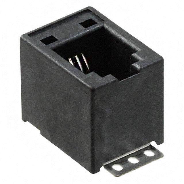
H7E@-N@P Accessories (Order Separately) (Common) ■ New H7E (Except for PCB-mounting Counter) The New H7E models are supplied with a mounting bracket (Y92F-34) and nut. Additionally, the Y92F-75/-76/-77B Flush Mounting Adapters shown here allow the New H7E models to be fitted to existing panel cutouts. Y92F-35 Compact Flush Mounting Bracket Panel Cutout Single mounting Dense mounting 47.6 2.4 18.6 4 (48 × No. of units − 2.5)+10.0 26 22.2+00.5 30 min. RST 22.2+00.5 45+00.5 Degree of protection (front): IP40 (not waterproof) (cid:127)The minimum mounting interval is 30 mm. The DIP switch of the H7E@-N can be operated in mounted condi- Note: An interval of 40 mm is recommended for easier wiring. tion. Vibration resistance and shock resistant are the same level as (cid:127)Do not allow the ambient temperature of the H7E@-N to exceed the the H7E@-N series. specifications (55°C). (cid:127)Mounting is possible onto panels with a thickness of 1 to 5 mm. Y92F-75 Flush Mounting Adapter for 26 × 45.3 Rectangular Cutout Use mounting bracket supplied with the Counter Two 3.5 dia. mounting holes Panel Cutout Two, M3 31 24.222.2 26 26 45.2 4 45.3 (Color: light gray) 48.2 63 63 72 Y92F-76 Flush Mounting Adapter for 27.5 × 52.5 Rectangular Cutout Panel Cutout Two 4.5 dia. countersunk holes Two, M4 50 38 24.2 22.2 38 27.5 RST (Color: light gray) 45.2 4 52.5 Use the Y92F-76 together with the Y92F-35 Compact 48.2 Flush Mounting Bracket. 60 Do not use the Flush Mounting Adapter supplied with the Counter. Y92F-77B Flush Mounting Adapter for 24.8 × 48.8 Rectangular Cutout Use mounting bracket supplied with the Counter Panel cutout 28.8 24.2 22.2 24.8 45.2 4 48.8 48.2 (Color: light gray) 53.8 Note: The mounting panel thickness should be between 1 and 5 mm. 27
H7E@-N@P Y92S-37 Wire-wrap Terminal (Set of Two Terminals) 44.8 Wire-wrap terminal (1 × 1 mm) 24 22 48 2 48.5 17.1 5 When using the Wire-wrap Terminal, be sure to use the correct wires Wire Bit Sleeve Wrapped state and peripheral devices. (The correct wires, bits and sleeves are shown in the table on the right.) AWG22 2-A 2-B Normal AWG24 1-A 1-B Normal AWG26 3-A 1-B Normal Y92S-36 Lithium Battery (3 V) 24.5 dia. 7.7 28
H7E@-N@P Precautions (Common) Refer to Safety Precautions for All Counters. ■ New H7E (Except for PCB-mounting Counter) !WARNING !CAUTION This product has a built-in lithium battery. Do not short-circuit the + If a voltage other than the rated one is applied, internal elements may and − terminals, charge, disassemble, deform, or expose the battery be damaged. to fire. The battery may explode (break), catch fire, or cause liquid Do not use the Counter in the following places: leakage. •Locations subject to direct sunlight. •Locations subject to corrosive gases. Do not use any battery other than the specified one (Y92S-36). Using •Locations subject to dust. another battery may cause liquid leakage or breakage, resulting in malfunction or injury. Before Use Reset Input and Count/Timer Input (cid:127)An insulation sheet has been inserted to maintain the quality of the (cid:127)The H7E operates using its built-in Battery. If the H7E is connected Totalizer in the event of a long period without use. Be sure to to a device that has +V and OUT terminals that are connected with remove this sheet before attempting to use the product. a diode as shown in the circuit diagram, the circuit indicated by the Remove the insulation sheet and press the Reset Key on the front arrow 1 or 2 will be formed when the device is turned OFF. As a panel of the Counter. (With the H7ER-N,-NV(-H),-NV1(-H), models, result, the H7E may be reset or count by one. It is recommended “0” or “0.0” will be displayed after 1 s.) that such devices not be connected to the H7E. Devices Insulation Sheet H7E@-N al Interncircuit Cinopuunt to/Tr irmeseer t input Reset Key (cid:127)Switch settings on the Counter must be performed before mounting (cid:127)If an excessive voltage is applied to the count/timer input or reset it to a control panel. input terminals, the internal elements may be damaged. (cid:127)Do not use the Counter in the following locations: Ensure that the following voltages are not exceeded: (cid:127)Locations subject to severe changes in temperature. (cid:127)PNP/NPN universal voltage input model: 30 VDC (cid:127)Locations subject to condensation as the result of high humidity. (cid:127)AC/DC voltage input model: At count/timer input:240 VAC (peak voltage: 338V) Mounting Precautions for Flush 240 VDC At reset input: No voltage can be applied. (No-voltage Mounting input) (cid:127)No-voltage input model: No voltage can be applied. Although the operating section is watertight (conforming to NEMA4, (cid:127)Avoid wiring close to high-tension or large-current lines. IP66), rubber packing is provided to avoid water leakage through the gap between the Counter and panel cutout. Unless this rubber pack- (cid:127)Do not remove the outer case when voltage is being applied to the ing is tightly squeezed on, water may permeate inside the panel. power supply terminals or the input terminals. Therefore, be sure to tighten the screws for fixing the Y92F-34 Flush (cid:127)The input for the H7E@-NFV-@ is a high-impedance circuit and so Mounting Bracket. (Excessive tightening may also deform the rubber influence from an induced voltage may result in malfunction. There- packing.) fore, when the input signal wiring is longer than 10 m (line capaci- tance of 120 pF/m, at room temperature), it is recommended that a Screw for the Flush Mounting Bracket CR filter or a bleeder resistor is connected. The wider side must Y92F-34 Adapter face the panel. Panel 29
H7E@-N@P Count Input, Timer Input or Reset Input AC/DC Multi-voltage Input Models to More than One H7E Counter at a (cid:127)When connecting count/timer input from an SSR to the Counter that operates with AC/DC voltage input, use OMRON’s G3TA-IA/ID Time SSR (for DC) whose leakage current is 0.1 mA max. or connect a bleeder resistor in parallel to the input circuit of the Counter. (cid:127)PNP/NPN Universal DC Voltage Input or Leakage current: 0.1 mA max. or or or *Bleeder resistor The voltage between terminals 1 and 2 must be 1.5 V maximum when the SSR is OFF. Backlight Power Supply or (cid:127)To reduce variation in the brightness of the backlight when using more than one H7E with a backlight, use the same power supply for all the backlights. Note:H (Reset ON) level must be 4.5 V minimum. 4.7 (kΩ)/N + V H = 4.7 (kΩ)/N + R (cid:127)No-voltage Input (cid:127)When connecting the DC power supply for the backlights, be sure to connect the polarities correctly. Input Verification with the H7ET Time or Counter Note:1. The leakage current of the transistor used for input must be less than 1 µA. (When the time range is not set to 0s to 2. The forward voltage of the diode must be as low as possible 999h59min59s) (i.e., 0.1 V maximum with an IF of 20 µA) so that the voltage between terminals 3 and 4 will be 0.5 V when the reset input The decimal point of the LCD blinks every other second while an is ON. input signal is being applied. If the decimal point is not blinking, the input signal is not being received correctly. Check the input signal Input and Power Supply connections. Unit Label for Time Counter and No-voltage Input Models Tachometer (cid:127)Do not impose voltage on the Counter if the Counter is a model that operates with no-voltage input, otherwise the internal circuit of the A unit label has been packed with the Counter. Use in accordance Counter may be damaged. with the application. Do not connect any single input signal in parallel to Counter models operating with no-voltage input and those operating with voltage input, otherwise the Counters may malfunction. (cid:127)When connecting a sensor to the Counter that operates with no- voltage input, make sure that the sensor has open collector output. Sensor Battery Replacement Remove the wiring when replacing the Battery. Do not come in con- 1 2 3 4 tact with any item to which high voltage is being applied. Doing so may result in electric shock. (cid:127)When connecting an open collector input from a transistor to the Before changing the Battery, the person should ensure that they are Counter that operates with no-voltage input, make sure that the not carrying any static electric charge. leakage current of the transistor is 1 µA maximum. Procedure for replacing the Battery (refer to the diagrams below): No-voltage Input and PNP/NPN Universal DC 1. Using the tool, pry open the lift-tab on the case. (1) Voltage Input Models 2. Pull the body out of its outer case. (2) 3. Lift the Battery up by the edge and remove it. (3) (cid:127)The operation of the Counter may be affected if the capacitance of When removing the Battery, do not come in contact with the dis- input lines exceeds 500 pF (about 10 m, with parallel wires of 2 x play area or any internal parts. 2mm). 4. Wipe the back of the new Battery before inserting it. Keep all wires as short as possible. When using shielded wire, line capacitance may occur. 5. Ensure that the + and – terminals are correctly oriented. 6. After replacing the Battery, re-insert the body into its case. (4) Check that the case is securely held in by the lift-tab. 30
H7E@-N@P 7. Press the Reset Key before use (not necessary for H7ER-N,-NV,- EN/IEC Standards NV1). (5) The count or timer input, reset input, and backlight power supply ter- Tool minals of the no-voltage input or PNP/NPN universal DC voltage (2) (1) input models (H7E@-N,-N1, H7E@-NV(-H),-NV1(-H)) are not iso- lated. A SELV power supply conforming to Appendix H of IEC61010-1 should be used for the count or timer input, reset input and backlight power supply terminals. A SELV power supply is a power supply for which the input and output have double or reinforced insulation, and (1) for which the output voltage is 30 Vrms with 42.4 V peak or 60 VDC max. (Only the H7E@-NV@-H has a backlight.) Battery (3) The terminals for count or timer input and reset input for AC/DC multi-voltage input models have basic insulation. Connect the reset input terminals to a device that does not have exposed current-carrying parts and has basic insulation for 240VAC. (4) Others If the indicator keeps flickering or is OFF, the internal battery may be close to the end of its service life. In such a case, it is suggested that the battery be replaced. (5) ■ PCB-mounting Counter Power Supply Battery Replacement (cid:127)Use the power supply within the applicable range indicated by the To prevent unwanted reset when replacing the battery, connect the following waveform, while considering the ripple and voltage fluctu- new battery before disconnecting the old one. Otherwise, the voltage ations of the circuit power source. supplied to the counter circuit drops, causing the present count value to reset. Voltage 3.6 V When designing the circuit board, providing two extra terminals for battery connection will make the switch must simpler. See the sche- 2.6 V matic diagram below: (cid:127)The H7E@-N@P changes its mode as shown below depending on the applied supply voltage. H7E@-N@P Internal circuit LCD operation Wiring polarity must be carefully observed, in order to prevent per- (V) Beyond supply voltage manent damage to the Counters. Exercise caution when inserting 3.6 the Counter in the socket, to prevent reversed polarity. Looks darker Applicable 3 Looks normal Normal operation range Approx. 2.6 Flashes Normal operation Battery life Approx. 2.2 guideline No display No operation 0 31
H7E@-N@P Inputs PC Board (Bad Example) PC Board (Good Example) Do not route the wiring of the count, timer, or reset inputs in the vicin- ity of, or in parallel to the wiring of high-voltage or inductive load cir- H7E@-N@P cuits (such as motors and relays). Also, keep the wiring as short as Placed far away from Large-current- possible. the power supply. consuming components Large-current- consuming components Wired in parallel with large- current-carrying H7E@-N@P components. Bypass Bypass capacitor capacitor H7E@-N@P Power supply Power supply When using the Counter in an environment where the Counter is subject to frequent occurrences of vibration or shock, or when mounting the Counter facing downwards or sideways, it is suggested Be careful not to apply voltages exceeding the following values to the that the Counter be directly soldered to a PCB instead of using sock- count, timer, or reset terminals, otherwise the internal circuit may be ets. damaged. To Conform to EN/IEC Standards No-voltage input: 3 VDC Input terminals have no insulation from power supply terminals. The General Information power supply terminals must be supplied from a SELV source in accordance with IEC61010-1 Annex H. SELV (separated extra-low Finish soldering under the conditions below. voltage) source is a power supply having double or reinforced insula- Solder the terminals within 5 seconds, at a solder iron tip tempera- tion between the primary and the secondary circuit and having out- ture of 250°C ± 10°C when using lead solder, and within 3 seconds, put voltage of 30 V rms max. and 42.4 V peak max. or 60 VDC max. at a solder iron tip temperature of 350°C ± 10°C when using lead- free solder. Cleaning Since the Counter is not flux-tight, do not use flux when soldering. To prevent damage, the exterior of the Counter must not be exposed Avoid automatic and dip soldering. Manually solder the Counter onto to organic solvents (3.g. paint thinner or benzine), strong alkalis, or a PC board, and avoid cleaning as much as possible. strong acids. When mounting the Counter on a PC board with components which Others consume higher current than the H7E@-N@P, observe the following precautions. •No user-serviceable parts. 1. Minimize the wiring (less than 50 mm) from the H7E@-N@P to the (cid:129)Return to OMRON for all repairs. power supply section. 2. Avoid placing the H7E@-N@P power, timer, counter, or reset input circuit in parallel with circuits that consume large currents, partic- ularly on the positive side. ALL DIMENSIONS SHOWN ARE IN MILLIMETERS. To convert millimeters into inches, multiply by 0.03937. To convert grams into ounces, multiply by 0.03527. In the interest of product improvement, specifications are subject to change without notice. 32
Terms and Conditions Agreement Read and understand this catalog. Please read and understand this catalog before purchasing the products. Please consult your OMRON representative if you have any questions or comments. Warranties. (a) Exclusive Warranty. Omron’s exclusive warranty is that the Products will be free from defects in materials and workmanship for a period of twelve months from the date of sale by Omron (or such other period expressed in writing by Omron). Omron disclaims all other warranties, express or implied. (b) Limitations. OMRON MAKES NO WARRANTY OR REPRESENTATION, EXPRESS OR IMPLIED, ABOUT NON-INFRINGEMENT, MERCHANTABILITY OR FITNESS FOR A PARTICULAR PURPOSE OF THE PRODUCTS. BUYER ACKNOWLEDGES THAT IT ALONE HAS DETERMINED THAT THE PRODUCTS WILL SUITABLY MEET THE REQUIREMENTS OF THEIR INTENDED USE. Omron further disclaims all warranties and responsibility of any type for claims or expenses based on infringement by the Products or otherwise of any intellectual property right. (c) Buyer Remedy. Omron’s sole obligation hereunder shall be, at Omron’s election, to (i) replace (in the form originally shipped with Buyer responsible for labor charges for removal or replacement thereof) the non-complying Product, (ii) repair the non-complying Product, or (iii) repay or credit Buyer an amount equal to the purchase price of the non-complying Product; provided that in no event shall Omron be responsible for warranty, repair, indemnity or any other claims or expenses regarding the Products unless Omron’s analysis confirms that the Products were properly handled, stored, installed and maintained and not subject to contamination, abuse, misuse or inappropriate modification. Return of any Products by Buyer must be approved in writing by Omron before shipment. Omron Companies shall not be liable for the suitability or unsuitability or the results from the use of Products in combination with any electrical or electronic components, circuits, system assemblies or any other materials or substances or environments. Any advice, recommendations or information given orally or in writing, are not to be construed as an amendment or addition to the above warranty. See http://www.omron.com/global/ or contact your Omron representative for published information. Limitation on Liability; Etc. OMRON COMPANIES SHALL NOT BE LIABLE FOR SPECIAL, INDIRECT, INCIDENTAL, OR CONSEQUENTIAL DAMAGES, LOSS OF PROFITS OR PRODUCTION OR COMMERCIAL LOSS IN ANY WAY CONNECTED WITH THE PRODUCTS, WHETHER SUCH CLAIM IS BASED IN CONTRACT, WARRANTY, NEGLIGENCE OR STRICT LIABILITY. Further, in no event shall liability of Omron Companies exceed the individual price of the Product on which liability is asserted. Suitability of Use. Omron Companies shall not be responsible for conformity with any standards, codes or regulations which apply to the combination of the Product in the Buyer’s application or use of the Product. At Buyer’s request, Omron will provide applicable third party certification documents identifying ratings and limitations of use which apply to the Product. This information by itself is not sufficient for a complete determination of the suitability of the Product in combination with the end product, machine, system, or other application or use. Buyer shall be solely responsible for determining appropriateness of the particular Product with respect to Buyer’s application, product or system. Buyer shall take application responsibility in all cases. NEVER USE THE PRODUCT FOR AN APPLICATION INVOLVING SERIOUS RISK TO LIFE OR PROPERTY OR IN LARGE QUANTITIES WITHOUT ENSURING THAT THE SYSTEM AS A WHOLE HAS BEEN DESIGNED TO ADDRESS THE RISKS, AND THAT THE OMRON PRODUCT(S) IS PROPERLY RATED AND INSTALLED FOR THE INTENDED USE WITHIN THE OVERALL EQUIPMENT OR SYSTEM. Programmable Products. Omron Companies shall not be responsible for the user’s programming of a programmable Product, or any consequence thereof. Performance Data. Data presented in Omron Company websites, catalogs and other materials is provided as a guide for the user in determining suitability and does not constitute a warranty. It may represent the result of Omron’s test conditions, and the user must correlate it to actual application requirements. Actual performance is subject to the Omron’s Warranty and Limitations of Liability. Change in Specifications. Product specifications and accessories may be changed at any time based on improvements and other reasons. It is our practice to change part numbers when published ratings or features are changed, or when significant construction changes are made. However, some specifications of the Product may be changed without any notice. When in doubt, special part numbers may be assigned to fix or establish key specifications for your application. Please consult with your Omron’s representative at any time to confirm actual specifications of purchased Product. Errors and Omissions. Information presented by Omron Companies has been checked and is believed to be accurate; however, no responsibility is assumed for clerical, typographical or proofreading errors or omissions. 2015.7 In the interest of product improvement, specifications are subject to change without notice. OMRON Corporation Industrial Automation Company http://www.ia.omron.com/ (c)Copyright OMRON Corporation 2015 All Right Reserved.
Mouser Electronics Authorized Distributor Click to View Pricing, Inventory, Delivery & Lifecycle Information: O mron: Y92F-76 Y92F-75 H7EC-NFV H7EC-NV H7EC-NV-H H7ER-NV H7ET-N1 H7ET-NFV H7ET-NV H7ET-NV1 Y92F-35 Y92F-77B H7ER-NV1 H7ER-NV1-H H7EC-N