ICGOO在线商城 > 开发板,套件,编程器 > 评估和演示板和套件 > XR20M1172L32-0A-EB
 Datasheet下载
- 型号: XR20M1172L32-0A-EB
- 制造商: Exar
- 库位|库存: xxxx|xxxx
- 要求:
| 数量阶梯 | 香港交货 | 国内含税 |
| +xxxx | $xxxx | ¥xxxx |
查看当月历史价格
查看今年历史价格
XR20M1172L32-0A-EB产品简介:
ICGOO电子元器件商城为您提供XR20M1172L32-0A-EB由Exar设计生产,在icgoo商城现货销售,并且可以通过原厂、代理商等渠道进行代购。 XR20M1172L32-0A-EB价格参考。ExarXR20M1172L32-0A-EB封装/规格:评估和演示板和套件, XR20M1172 UART Interface Evaluation Board。您可以下载XR20M1172L32-0A-EB参考资料、Datasheet数据手册功能说明书,资料中有XR20M1172L32-0A-EB 详细功能的应用电路图电压和使用方法及教程。
MaxLinear, Inc. 的 XR20M1172L32-0A-EB 是一款评估和演示板,主要用于评估 MaxLinear 的 XR20M1172 系列射频收发器芯片的性能和功能。以下是该评估板的主要应用场景:

 1. 无线通信系统开发
XR20M1172L32-0A-EB 可用于开发和测试各种无线通信系统,例如蜂窝基站、小基站(Small Cell)、中继站等。它支持多种无线通信标准,如 LTE、5G NR 和其他专有协议,适用于新一代无线网络的研发。

 2. 雷达系统设计
该评估板也可应用于雷达系统的设计与测试,包括汽车雷达、工业雷达以及气象雷达等。XR20M1172 芯片具有高线性度和低噪声的特点,适合需要高精度和高灵敏度的雷达应用。

 3. 物联网(IoT)设备
XR20M1172L32-0A-EB 可用于开发物联网设备中的射频模块,支持低功耗和高性能的无线传输,适用于智能家居、智慧城市、工业自动化等领域。

 4. 卫星通信
该评估板能够帮助工程师测试和优化卫星通信系统的射频性能,包括地面站设备和卫星终端。其宽频带和高动态范围特性非常适合卫星通信的需求。

 5. 测试与测量设备
XR20M1172L32-0A-EB 可作为测试与测量设备的一部分,用于评估射频信号的质量和性能。例如,在频谱分析仪、信号发生器和其他射频测试设备中使用。

 6. 军事和航空航天
在军事和航空航天领域,XR20M1172L32-0A-EB 可用于开发高性能的通信和导航系统,满足严苛环境下的高可靠性要求。

 总结
XR20M1172L32-0A-EB 提供了一个灵活且强大的平台,使工程师能够快速评估和验证 XR20M1172 射频收发器的功能,从而加速产品开发周期。无论是无线通信、雷达系统还是物联网设备,这款评估板都能为用户提供可靠的射频解决方案。
| 参数 | 数值 |
| 产品目录 | 编程器,开发系统 |
| 描述 | EVAL BOARD FOR XR20M1172 32QFN |
| 产品分类 | |
| 品牌 | Exar Corporation |
| 数据手册 | http://www.exar.com/Common/Content/Document.ashx?id=1407 |
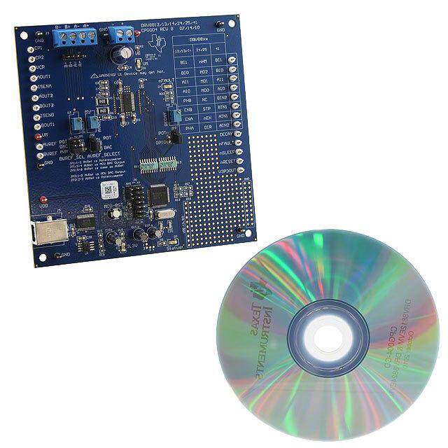
| 产品图片 |
|
| 产品型号 | XR20M1172L32-0A-EB |
| rohs | 无铅 / 符合限制有害物质指令(RoHS)规范要求 |
| 产品系列 | - |
| 主要属性 | 2 通道 (双路) |
| 主要用途 | 接口,UART |
| 使用的IC/零件 | XR20M1172 |
| 其它名称 | 1016-1624 |
| 嵌入式 | 否 |
| 所含物品 | 板 |
| 标准包装 | 1 |
| 辅助属性 | I²C 和 SPI 接口 |


- 商务部:美国ITC正式对集成电路等产品启动337调查
- 曝三星4nm工艺存在良率问题 高通将骁龙8 Gen1或转产台积电
- 太阳诱电将投资9.5亿元在常州建新厂生产MLCC 预计2023年完工
- 英特尔发布欧洲新工厂建设计划 深化IDM 2.0 战略
- 台积电先进制程称霸业界 有大客户加持明年业绩稳了
- 达到5530亿美元!SIA预计今年全球半导体销售额将创下新高
- 英特尔拟将自动驾驶子公司Mobileye上市 估值或超500亿美元
- 三星加码芯片和SET,合并消费电子和移动部门,撤换高东真等 CEO
- 三星电子宣布重大人事变动 还合并消费电子和移动部门
- 海关总署:前11个月进口集成电路产品价值2.52万亿元 增长14.8%


PDF Datasheet 数据手册内容提取
XR20M1172 TWO CHANNEL I2C/SPI UART WITH 64-BYTE FIFO JULY 2018 REV. 1.2.1 GENERAL DESCRIPTION FEATURES The XR20M11721 is a high performance two channel 1.62 to 3.6 Volt Operation universal asynchronous receiver and transmitter Selectable I2C/SPI Interface (UART) with 64 byte TX and RX FIFOs and a SPI clock frequency up to selectable I2C/SPI slave interface. The XR20M1172 operates from 1.62 to 3.63 volts. The standard ■ 18 MHz at 3.3 V features include 16 selectable TX and RX FIFO ■ 16 MHz at 2.5 V trigger levels, automatic hardware (RTS/CTS) and ■ 8 MHz at 1.8 V software (Xon/Xoff) flow control, and a complete modem interface. Onboard registers provide the user Full-featured UART with operational status and data error flags. An ■ Data rate of up to 16 Mbps at 3.3 V internal loopback capability allows system ■ Data rate of up to 12.5 Mbps at 2.5 V diagnostics. Additional enhanced features includes a programmable fractional baud rate generator and 8X ■ Data rate of up to 8 Mbps at 1.8 V and 4X sampling rate that allows for a maximum baud ■ Fractional Baud Rate Generator rate of 16 Mbps at 3.3V. The XR20M1172 is available ■ Transmit and Receive FIFOs of 64 bytes in the 32-pin QFN and 28-pin TSSOP packages. The ■ 16 Selectable TX and RX FIFO Trigger Levels 32-pin QFN package has the EN485# and ENIR# pins to allow the UART to power-up in the Auto ■ Automatic Hardware (RTS/CTS) Flow Control RS485 mode or the Infrared mode. ■ Automatic Software (Xon/Xoff) Flow Control NOTE: 1 Covered by U.S. Patent #5,649,122 ■ Halt and Resume Transmission Control ■ Automatic RS-485 Half-duplex Direction APPLICATIONS Control Output via RTS# Portable Appliances ■ Wireless Infrared (IrDA 1.0 and 1.1) Encoder/ Battery-Operated Devices Decoder ■ Automatic sleep mode (< 30 uA at 3.3V) Cellular Data Devices ■ General Purpose I/Os Factory Automation and Process Controls ■ Full modem interface Crystal oscillator (up to 24MHz) or external clock (up to 64MHz) input 32-QFN and 28-TSSOP packages FIGURE 1. XR20M1172 BLOCK DIAGRAM VCC 1.62V – 3.63V Channel 1 64 Byte TXA ENIR# UART TX FIFO RXA EN485# Regs 64 Byte RTSA# IRQ# RX FIFO CTSA# RESET# BRG SDA SCK I2C/ SPI GPIOs GPIO[7:0] A0/CS# Interface A1/SI TXB SO RXB UART Channel 2 I2C/SPI# Crystal (Similar to Channel1) RTSB# Osc / CTSB# Buffer X X T T A A L L 1 2 1
XR20M1172 TWO CHANNEL I2C/SPI UART WITH 64-BYTE FIFO REV. 1.2.1 FIGURE 2. PIN OUT ASSIGNMENT # # B A R R T T RESET# GPIO1/D GPIO5/D RTSA# RQ# EN485# ENIR# SCK I 24 23222120191817 CTSA# 25 16 CTSB# GPIO4/DSRA# 26 15 RTSB# GPIO6/CDA# 27 14 GPIO3/RIB# GPIO7/RIA# 28 32-pin QFN 13 GPIO0/DSRB# VCC 29 12 GND A0/CS# 30 11 GPIO2/CDB# A1/SI 31 10 XTAL2 SEL_I2C_SPI# 32 9 XTAL1 1 2 3 4 5 6 7 8 C. O A B A A B C. N. S SD RX RX TX TX N. VCC 1 28 GPIO7/RIA# A0/CS# 2 27 GPIO6/CDA# A1/SI 3 26 GPIO4/DSRA# I2C/SPI# 4 25 CTSA# SO 5 24 RESET# SDA 6 23 GPIO1/DTRB# RXB 7 22 GPIO5/DTRA# 28-Pin TSSOP RXA 8 21 RTSA# TXA 9 20 IRQ# TXB 10 19 SCK XTAL1 11 18 CTSB# XTAL2 12 17 RTSB# GPIO2/CDB# 13 16 GPIO3/RIB# GND 14 15 GPIO0/DSRB# 2
XR20M1172 REV. 1.2.1 TWO CHANNEL I2C/SPI UART WITH 64-BYTE FIFO ORDERING INFORMATION(1) OPERATING PART NUMBER LEAD-FREE PACKAGE PACKAGING METHOD TEMPERATURE RANGE XR20M1172IL32-F 32-pin QFN Tray XR20M1172IL32TR-F 32-pin QFN Tape and Reel -40°C to +85°C Yes(2) XR20M1172IG28-F 28-Lead TSSOP Tube XR20M1172IG28TR-F 28-Lead TSSOP Tape and Reel XR20M1172G28-0A-EB Evaluation Board for TSSOP-28, RS-232 and RS-485 capable XR20M1172G28-0B-EB Evaluation Board for TSSOP-28, RS-232 only XR20M1172L32-0A-EB Evaluation Board for QFN-32, RS-232 and RS-485 capable XR20M1172L32-0B-EB Evaluation Board for QFN-32, RS-232 only NOTES: 1. Refer to www.exar.com/XR20M1172 for most up-to-date Ordering Information. 2. Visit www.exar.com for additional information on Environmental Rating. PIN DESCRIPTIONS Pin Description 32-QFN 28-TSSOP NAME TYPE DESCRIPTION PIN # PIN# I2C (SPI) INTERFACE SO 2 5 O SPI data output pin. If SPI configuration is selected then this pin is a three-stateable output pin. If I2C-bus configuration is selected, this pin is undefined and must be left unconnected. SDA 3 6 O I2C-bus data input/output (open-drain). If SPI configuration is selected, then this pin is undefined and must be connected to VCC. RXB 4 7 I UART Receive Data or Infrared Receive Data. UART receive data input must idle HIGH. Infrared receive data input must idle LOW. If this pin is not used, tie it to VCC or pull it high via a 100k ohm resistor. RXA 5 8 I UART Receive Data or Infrared Receive Data. UART receive data input must idle HIGH. Infrared receive data input must idle LOW. If this pin is not used, tie it to VCC or pull it high via a 100k ohm resistor. TXA 6 9 O UART Transmit Data or Infrared Encoder Data. In the standard UART Transmit Data mode, the TX signal will be HIGH during reset or idle (no data). In the Infrared mode, the inactive state (no data) for the Infrared encoder/decoder interface is LOW. If ithis pin is not used, it should be left unconnected. 3
XR20M1172 TWO CHANNEL I2C/SPI UART WITH 64-BYTE FIFO REV. 1.2.1 Pin Description 32-QFN 28-TSSOP NAME TYPE DESCRIPTION PIN # PIN# TXB 7 10 O UART Transmit Data or Infrared Encoder Data. In the standard UART Transmit Data mode, the TX signal will be HIGH during reset or idle (no data). In the Infrared mode, the inactive state (no data) for the Infrared encoder/decoder interface is LOW. If ithis pin is not used, it should be left unconnected. XTAL1 9 11 I Crystal or external clock input. XTAL2 10 12 O Crystal or buffered clock output. GPIO2/CDB# 11 13 I/O General purpose I/O pin or UART Carrier-Detect. If this pin is an input and is unused, it should be connected to VCC or GND. If this pin is an output and is unused, it should be left unconnected. See IOControl[1] and IODir register. GND 12 14 Pwr Power supply common, ground. GPIO0/DSRB# 13 15 I/O General purpose I/O pin or UART Data-Set-Ready. If this pin is an input and is unused, it should be connected to VCC or GND. If this pin is an output and is unused, it should be left unconnected. See IOControl[1] and IODir register. GPIO3/RIB# 14 16 I/O General purpose I/O pin or UART Ring-Indicator. If this pin is an input and is unused, it should be connected to VCC or GND. If this pin is an output and is unused, it should be left unconnected. See IOControl[1] and IODir register. RTSB# 15 17 O UART Request-To-Send. This output can be used for Auto RTS Hard- ware Flow Control, Auto RS-485 Half-Duplex direction control or as a general purpose output. If unused, this pin should be left unconnected. CTSB# 16 18 I UART Clear-To-Send. This input can be used for Auto CTS Hardware Flow Control or as a general purpose input. If unused, this pin should be connected to VCC or GND. SCL 17 19 I I2C-bus or SPI serial input clock. When the I2C-bus interface is selected, the serial clock idles HIGH. When the SPI interface is selected, the serial clock idles LOW. ENIR# 18 - I Enable IR Mode (internal pull-up resistor). This pin is sampled upon power-up. If this pin is HIGH, then the TX output and RX input will behave as the UART transmit data output and UART receive data input. If this pin is LOW, then the TX output and RX input will behave as the infrared encoder data output and the infrared receive data input. EN485# 19 - I Enable Auto RS-485 Half-Duplex Mode (internal pull-up resistor). This pin is sampled upon power-up. If this pin is HIGH, then the RTS# output can be used for Auto RTS Hardware Flow Control or as a general purpose output. If this pin is LOW, then the RTS# output is the Auto RS-485 Half-Duplex direction control pin. IRQ# 20 20 O Interrupt output (open-drain, active LOW). For proper operation, a pull-up resistor is required on this pin. 4
XR20M1172 REV. 1.2.1 TWO CHANNEL I2C/SPI UART WITH 64-BYTE FIFO Pin Description 32-QFN 28-TSSOP NAME TYPE DESCRIPTION PIN # PIN# RTSA# 21 21 O UART Request-To-Send. This output can be used for Auto RTS Hardware Flow Control, Auto RS-485 Half-Duplex direction control or as a general purpose output. If unused, this pin should be left unconnected. GPIO5/DTRA# 22 22 I/O General purpose I/O pin or UART Data-Terminal-Ready. If this pin is an input and is unused, it should be connected to VCC or GND. If this pin is an output and is unused, it should be left unconnected. See IOControl[1] and IODir register. GPIO1/DTRB# 23 23 I/O General purpose I/O pin or UART Data-Terminal-Ready. If this pin is an input and is unused, it should be connected to VCC or GND. If this pin is an output and is unused, it should be left unconnected. See IOControl[1] and IODir register. RESET# 24 24 I Reset (active LOW) - A longer than 40 ns LOW pulse on this pin will reset the internal registers and all outputs. The UART transmitter output will be idle and the receiver input will be ignored. CTSA# 25 25 I UART Clear-To-Send. This input can be used for Auto CTS Hardware Flow Control or as a general purpose input. If unused, this pin should be connected to VCC or GND. GPIO4/DSRA# 26 26 I/O General purpose I/O pin or UART Data-Set-Ready. If this pin is an input and is unused, it should be connected to VCC or GND. If this pin is an output and is unused, it should be left unconnected. See IOControl[1] and IODir register. GPIO6/CDA# 27 27 I/O General purpose I/O pin or UART Carrier-Detect. If this pin is an input and is unused, it should be connected to VCC or GND. If this pin is an output and is unused, it should be left unconnected. See IOControl[1] and IODir register. GPIO7/RIA# 28 28 I/O General purpose I/O pin or UART Ring-Indicator. If this pin is an input and is unused, it should be connected to VCC or GND. If this pin is an output and is unused, it should be left unconnected. See IOControl[1] and IODir register. VCC 29 1 Pwr 1.62V to 3.63V power supply. A0/CS# 30 2 I I2C-bus device address select A0 or SPI chip select. If I2C-bus configuration is selected, this pin along with the A1 pin allows user to change the device’s base address. If SPI configuration is selected, this pin is the SPI chip select pin (Schmitt-trigger, active LOW). A1/SI 31 3 I I2C-bus device address select A1 or SPI data input pin. If I2C-bus onfiguration is selected, this pin along with A0 pin allows user to change the device’s base address. If SPI configuration is selected, this pin is the SPI data input pin. I2C/SPI# 32 4 I I2C-bus or SPI interface select. I2C-bus interface is selected if this pin is HIGH. SPI interface is selected if this pin is LOW 5
XR20M1172 TWO CHANNEL I2C/SPI UART WITH 64-BYTE FIFO REV. 1.2.1 Pin Description 32-QFN 28-TSSOP NAME TYPE DESCRIPTION PIN # PIN# - PAD - Pwr The center pad on the backside of the QFN package is metallic and is not electrically connected to anything inside the device. It must be soldered on to the PCB and may be optionally connected to GND on the PCB. The thermal pad size on the PCB should be the approximate size of this center pad and should be solder mask defined. The solder mask opening should be at least 0.0025" inwards from the edge of the PCB thermal pad. NC 1, 8 - - No Connection. Pin type: I=Input, O=Output, I/O= Input/output, OD=Output Open Drain. 6
XR20M1172 REV. 1.2.1 TWO CHANNEL I2C/SPI UART WITH 64-BYTE FIFO 1.0 PRODUCT DESCRIPTION The XR20M1172 integrates a selectable I2C/SPI bus interface with an enhanced two-channel Universal Asynchronous Receiver and Transmitter (UART). The configuration registers set is 16550 UART compatible for control, status and data transfer. Additionally, each channel of the XR20M1172 has 64-bytes of transmit and receive FIFOs, automatic RTS/CTS hardware flow control, automatic Xon/Xoff and special character software flow control, programmable transmit and receive FIFO trigger levels, infrared encoder and decoder (IrDA 1.0 and 1.1), programmable fractional baud rate generator with a prescaler of divide by 1 or 4, and data rate up to 16 Mbps with 4X sampling clock rate. The XR20M1172 is a 1.62V to 3.63V device. The XR20M1172 is fabricated with an advanced CMOS process. Enhanced Features The XR20M1172 UART provides a solution that supports 64 bytes of transmit and receive FIFO memory, instead of 16 bytes in the industry standard 16C550. The XR20M1172 is designed to work with low supply voltage and high performance data communication systems, that require fast data processing time. Increased performance is realized in the XR20M1172 by the larger transmit and receive FIFOs, FIFO trigger level control and automatic flow control mechanism. This allows the external processor to handle more networking tasks within a given time. For example, the 16C550 with a 16 byte FIFO, unloads 16 bytes of receive data in 1.53 ms (This example uses a character length of 11 bits, including start/stop bits at 115.2 Kbps). This means the external CPU will have to service the receive FIFO at 1.53 ms intervals. However with the 64 byte FIFO in the XR20M1172, the data buffer will not require unloading/loading for 6.1 ms. This increases the service interval giving the external CPU additional time for other applications and reducing the overall UART interrupt servicing time. In addition, the programmable FIFO level trigger interrupt and automatic hardware/software flow control is uniquely provided for maximum data throughput performance especially when operating in a multi-channel system. The combination of the above greatly reduces the CPU’s bandwidth requirement, increases performance, and reduces power consumption. The XR20M1172 supports a half-duplex output direction control signaling pin, RTS#, to enable and disable the external RS-485 transceiver operation. It automatically switches the logic state of the output pin to the receive state after the last stop-bit of the last character has been shifted out of the transmitter. After receiving, the logic state of the output pin switches back to the transmit state when a data byte is loaded in the transmitter. The auto RS-485 direction control pin is not activated after reset. To activate the direction control function, user has to set EFCR bit-4 to “1”. This pin is HIGH for receive state and LOW for transmit state. The polarity of the RTS# pin can be inverted via EFCR bit-5. Data Rate The XR20M1172 is capable of operation up to 16 Mbps at 3.3V with 4X internal sampling clock rate, 8 Mbps at 3.3V with 8X sampling clock rate, and 4 Mbps at 3.3V with 16X internal sampling clock rate. The device can operate with an external 24 MHz crystal on pins XTAL1 and XTAL2, or external clock source of up to 64 MHz on XTAL1 pin. With a typical crystal of 14.7456 MHz and through a software option, the user can set the prescaler bit for data rates of up to 3.68 Mbps. The rich feature set of the XR20M1172 is available through the internal registers. Automatic hardware/software flow control, programmable transmit and receive FIFO trigger levels, programmable TX and RX baud rates, infrared encoder/decoder interface, modem interface controls, and a sleep mode are all standard features. Following a power on reset or an external reset, the XR20M1172 is software compatible with previous generation of UARTs, 16C450, 16C550 and 16C2550. 7
XR20M1172 TWO CHANNEL I2C/SPI UART WITH 64-BYTE FIFO REV. 1.2.1 2.0 FUNCTIONAL DESCRIPTIONS 2.1 CPU Interface The XR20M1172 can operate with either an I2C-bus interface or an SPI interface. The CPU interface is selected via the I2C/SPI# input pin. 2.1.1 I2C-bus Interface The I2C-bus interface is compliant with the Standard-mode and Fast-mode I2C-bus specifications. The I2C- bus interface consists of two lines: serial data (SDA) and serial clock (SCL). In the Standard-mode, the serial clock and serial data can go up to 100 kbps and in the Fast-mode, the serial clock and serial data can go up to 400 kbps. The first byte sent by an I2C-bus master contains a start bit (SDA transition from HIGH to LOW when SCL is HIGH), 7-bit slave address and whether it is a read or write transaction. The next byte is the sub- address that contains the address of the register to access. The XR20M1172 responds to each write with an acknowledge (SDA driven LOW by XR20M1172 for one clock cycle when SCL is HIGH). If the TX FIFO is full, the XR20M1172 will respond with a negative acknowledge (SDA driven HIGH by XR20M1172 for one clock cycle when SCL is HIGH) when the CPU tries to write to the TX FIFO. The last byte sent by an I2C-bus master is a stop bit (SDA transition from LOW to HIGH when SCL is HIGH). See Figures 3 - 5 below. For complete details, see the I2C-bus specifications. FIGURE 3. I2C START AND STOP CONDITIONS SDA SCL S P START condition STOP condition FIGURE 4. MASTER WRITES TO SLAVE (XR20M1172) SLAVE REGISTER S W A A nDATA A P ADDRESS ADDRESS White block: host to UART Grey block: UART to host FIGURE 5. MASTER READS FROM SLAVE (XR20M1172) SLAVE REGISTER SLAVE S W A A S R A nDATA A LAST DATA NA P ADDRESS ADDRESS ADDRESS White block: host to UART Grey block: UART to host 8
XR20M1172 REV. 1.2.1 TWO CHANNEL I2C/SPI UART WITH 64-BYTE FIFO FIGURE 6. I2C DATA FORMATS Data transferred (n bytes + acknowledge) SLAVE Master write: S W A DATA A DATA A P ADDRESS START condition write acknowledge acknowledge acknowledge STOP condition Data transferred (n bytes + acknowledge) SLAVE Master read: S R A DATA A DATA NA P ADDRESS START condition read acknowledge acknowledge Not acknowledge STOP condition Data transferred (n bytes + Data transferred (n bytes + acknowledge) acknowledge) Combined S SLAVE R/W A DATA A Sr SLAVE R/W A DATA A P formats: ADDRESS ADDRESS START condition Read or acknowledge acknowledge Repeated Read or acknowledge acknowledge STOP condition write START condition write Direction of transfer may change at this point 9
XR20M1172 TWO CHANNEL I2C/SPI UART WITH 64-BYTE FIFO REV. 1.2.1 2.1.1.1 I2C-bus Addressing There could be many devices on the I2C-bus. To distinguish itself from the other devices on the I2C-bus, there are eight possible slave addresses that can be selected for the XR20M1172 using the A1 and A0 address lines. Table 1 below shows the different addresses that can be selected. Note that there are two different ways to select each I2C address. TABLE 1: XR20M1172 I2C ADDRESS MAP A1 A0 I2C ADDRESS VCC VCC 0x60 (0110 000X) VCC GND 0x62 (0110 001X) VCC SCL 0x64 (0110 010X) VCC SDA 0x66 (0110 011X) GND VCC 0x68 (0110 100X) GND GND 0x6A (0110 101X) GND SCL 0x6C (0110 110X) GND SDA 0x6E (0110 111X) SCL VCC 0x60 (0110 000X) SCL GND 0x62 (0110 001X) SCL SCL 0x64 (0110 010X) SCL SDA 0x66 (0110 011X) SDA VCC 0x68 (0110 100X) SDA GND 0x6A (0110 101X) SDA SCL 0x6C (0110 110X) SDA SDA 0x6E (0110 111X) An I2C sub-address is sent by the I2C master following the slave address. The sub-address contains the UART register address being accessed. A read or write transaction is determined by bit-0 of the slave address (HIGH = Read, LOW = Write). Table 2 below lists the functions of the bits in the I2C sub-address. TABLE 2: I2C SUB-ADDRESS (REGISTER ADDRESS) BIT FUNCTION 7 Reserved 6:3 UART Internal Register Address A3:A0 2:1 UART Channel Select ’00’ = UART Channel A ’01’ = UART Channel B other values are reserved 0 Reserved After the last read or write transaction, the I2C-bus master will set the SCL signal back to its idle state (HIGH). 10
XR20M1172 REV. 1.2.1 TWO CHANNEL I2C/SPI UART WITH 64-BYTE FIFO 2.1.2 SPI Bus Interface The SPI interface consists of four lines: serial clock (SCL), chip select (CS#), slave output (SO) and slave input (SI). The serial clock, slave output and slave input can be as fast as 18 MHz at 3.3V. To access the device in the SPI mode, the CS# signal for the XR20M1172 is asserted by the SPI master, then the SPI master starts toggling the SCL signal with the appropriate transaction information. The first bit sent by the SPI master includes whether it is a read or write transaction and the UART register being accessed. See Table 3 below. TABLE 3: SPI FIRST BYTE FORMAT BIT FUNCTION 7 Read/Write# Logic 1 = Read Logic 0 = Write 6:3 UART Internal Register Address A3:A0 2:1 UART Channel Select ’00’ = UART Channel A ’01’ = UART Channel B Other values are reserved 0 Reserved FIGURE 7. SPI WRITE SCLK SI R/W A3 A2 A1 A0 0 CH X D7 D6 D5 D4 D3 D2 D1 D0 FIGURE 8. SPI READ SCLK SI R/W A3 A2 A1 A0 0 CH X SO D7 D6 D5 D4 D3 D2 D1 D0 11
XR20M1172 TWO CHANNEL I2C/SPI UART WITH 64-BYTE FIFO REV. 1.2.1 The 64 byte TX FIFO can be loaded with data or 64 byte RX FIFO data can be unloaded in one SPI write or read sequence. FIGURE 9. SPI FIFO WRITE SCLK SO R/W A3 A2 A1 A0 0 CH X D7 D6 D5 D4 D3 D2 D1 D0 D7 D6 D5 D4 D3 D2 D1 D0 last bit FIGURE 10. SPI FIFO READ SCLK R/W A3 A2 A1 A0 0 CH X D7 D6 D5 D4 D3 D2 D1 D0 D7 D6 D5 D4 D3 D2 D1 D0 last bit After the last read or write transaction, the SPI master will set the SCL signal back to its idle state (LOW). 2.2 Device Reset The RESET# input resets the internal registers and the serial interface outputs in the UART to its default state (see Table 16). An active low pulse of longer than 40 ns duration will be required to activate the reset function in the device. 2.3 Internal Registers The XR20M1172 has a set of enhanced registers for control, monitoring and data loading and unloading. The configuration register set is compatible to the industry standard ST16C550. These registers function as data holding registers (THR/RHR), interrupt status and control registers (ISR/IER), a FIFO control register (FCR), receive line status and control registers (LSR/LCR), modem status and control registers (MSR/MCR), programmable data rate (clock) divisor registers (DLL/DLM/DLD), and a user accessible Scratchpad Register (SPR). Beyond the general 16C550 features and capabilities, the XR20M1172 offers enhanced feature registers (EFR, Xon/Xoff 1, Xon/Xoff 2, TCR, TLR, TXLVL, RXLVL, IODir, IOState, IOIntEna, IOControl, EFCR and DLD) that provide automatic RTS and CTS hardware flow control, Xon/Xoff software flow control, automatic RS-485 half-duplex direction output enable/disable, TX and RX FIFO level counters, and programmable FIFO trigger level control. For complete details, see “Section 3.0, UART Internal Registers” on page 26. 12
XR20M1172 REV. 1.2.1 TWO CHANNEL I2C/SPI UART WITH 64-BYTE FIFO 2.4 IRQ# Output The IRQ# interrupt output changes according to the operating mode and enhanced features setup. Table 4 and 5 summarize the operating behavior for the transmitter and receiver. Also see Figures 21 through 35. TABLE 4: IRQ# PIN OPERATION FOR TRANSMITTER Auto RS485 FCR BIT-0 = 0 FCR BIT-0 = 1 Mode (NON-FIFO MODE) (FIFO MODE) IRQ# Pin NO HIGH = a byte in THR HIGH = FIFO above trigger level LOW = THR empty LOW = FIFO below trigger level or FIFO empty IRQ# Pin YES HIGH = a byte in THR HIGH = FIFO above trigger level LOW = transmitter empty LOW = FIFO below trigger level or transmitter empty TABLE 5: IRQ# PIN OPERATION FOR RECEIVER FCR BIT-0 = 0 FCR BIT-0 = 1 (NON-FIFO MODE) (FIFO MODE) IRQ# Pin HIGH = no data HIGH = FIFO below trigger level LOW = 1 byte LOW = FIFO above trigger level The Non-FIFO mode is enabled by default for 16450 compatibility. For normal operation, the FIFO mode must be enabled. 13
XR20M1172 TWO CHANNEL I2C/SPI UART WITH 64-BYTE FIFO REV. 1.2.1 2.5 Crystal Oscillator or External Clock Input The XR20M1172 includes an on-chip oscillator (XTAL1 and XTAL2) to produce a clock for both UART sections in the device. The CPU data bus does not require this clock for bus operation. The crystal oscillator provides a system clock to the Baud Rate Generators (BRG) section found in each of the UART. XTAL1 is the input to the oscillator or external clock buffer input with XTAL2 pin being the output. Please note that the input XTAL1 is not 5V tolerant and so the maximum at the pin should be VCC. For programming details, see ““Section 2.6, Programmable Baud Rate Generator with Fractional Divisor” on page 14.” FIGURE 11. TYPICAL OSCILLATOR CONNECTIONS XTAL1 XTAL2 R1 R2 0 –120 (cid:1105) Optional 500K –1M(cid:1105) 1.8432 MHz to 24 MHz Y1 C1 C2 10-22 pF 10-22 pF The on-chip oscillator is designed to use an industry standard microprocessor crystal (parallel resonant, fundamental frequency with 10-22 pF capacitance load, ESR of 20-120 ohms and 100 ppm frequency tolerance) connected externally between the XTAL1 and XTAL2 pins (see Figure 11). The programmable Baud Rate Generator is capable of operating with a crystal oscillator frequency of up to 24 MHz. However, with an external clock input on XTAL1 pin, it can extend its operation up to 64 MHz (16 Mbps serial data rate) at 3.3V with an 4X sampling rate. For further reading on the oscillator circuit please see the Application Note DAN108 on the EXAR web site at http://www.exar.com. 2.6 Programmable Baud Rate Generator with Fractional Divisor Each UART has its own Baud Rate Generator (BRG) with a prescaler for the transmitter and receiver. The prescaler is controlled by a software bit in the MCR register. The MCR register bit-7 sets the prescaler to divide the input crystal or external clock by 1 or 4. The output of the prescaler clocks to the BRG. The BRG further divides this clock by a programmable divisor between 1 and (216 - 0.0625) in increments of 0.0625 (1/16) to obtain a 16X, 8X or 4X sampling clock of the serial data rate. The sampling clock is used by the transmitter for data bit shifting and receiver for data sampling. The BRG divisor (DLL, DLM and DLD registers) defaults to the value of ’1’ (DLL = 0x01, DLM = 0x00 and DLD = 0x00) upon reset. Therefore, the BRG must be programmed during initialization to the operating data rate. The DLL and DLM registers provide the integer part of the divisor and the DLD register provides the fractional part of the dvisior. The four lower bits of the DLD are used to select a value from 0 (for setting 0000) to 0.9375 or 15/16 (for setting 1111). Programming the Baud Rate Generator Registers DLL, DLM and DLD provides the capability for selecting the operating data rate. Table 6 shows the standard data rates available with a 24MHz crystal or external clock at 16X clock rate. If the pre-scaler is used (MCR bit-7 = 1), the output data rate will be 4 times less than that shown in Table 6. At 8X sampling rate, these data rates would double and at 4X sampling rate, these data rates would quadruple. Also, when using 8X sampling mode, the bit time will have a jitter of ± 1/16 whenever the DLD is non-zero and is an odd number. 14
XR20M1172 REV. 1.2.1 TWO CHANNEL I2C/SPI UART WITH 64-BYTE FIFO When using 4X sampling mode, the bit time will have a jitter of ± 1/8 whenever DLD is non-zero, odd and not a multiple of 4. When using a non-standard data rate crystal or external clock, the divisor value can be calculated with the following equation(s): Required Divisor (decimal)=(XTAL1 clock frequency / prescaler) /(serial data rate x 16), with 16X mode, DLD[5:4]=’00’ Required Divisor (decimal)= (XTAL1 clock frequency / prescaler / (serial data rate x 8), with 8X mode, DLD[5:4] = ’01’ Required Divisor (decimal)= (XTAL1 clock frequency / prescaler / (serial data rate x 4), with 4X mode, DLD[5:4] = ’10’ The closest divisor that is obtainable in the XR20M1172 can be calculated using the following formula: ROUND( (Required Divisor - TRUNC(Required Divisor) )*16)/16 + TRUNC(Required Divisor), where DLM = TRUNC(Required Divisor) >> 8 DLL = TRUNC(Required Divisor) & 0xFF DLD = ROUND( (Required Divisor-TRUNC(Required Divisor) )*16) In the formulas above, please note that: TRUNC (N) = Integer Part of N. For example, TRUNC (5.6) = 5. ROUND (N) = N rounded towards the closest integer. For example, ROUND (7.3) = 7 and ROUND (9.9) = 10. A >> B indicates right shifting the value ’A’ by ’B’ number of bits. For example, 0x78A3 >> 8 = 0x0078. FIGURE 12. BAUD RATE GENERATOR DLL, DLM and DLD Registers Prescaler MCR Bit-7=0 Divide by 1 (default) 16X or 8X or 4X XTAL1 Crystal Fractional Baud Sampling Osc/ Rate Generator Rate Clock XTAL2 Buffer Logic to Transmitter Prescaler and Receiver Divide by 4 MCR Bit-7=1 15
XR20M1172 TWO CHANNEL I2C/SPI UART WITH 64-BYTE FIFO REV. 1.2.1 TABLE 6: TYPICAL DATA RATES WITH A 24 MHZ CRYSTAL OR EXTERNAL CLOCK AT 16X SAMPLING Required DIVISOR FOR DIVISOR DLM PROGRAM DLL PROGRAM DLD PROGRAM DATA ERROR Output Data 16x Clock OBTAINABLE IN VALUE (HEX) VALUE (HEX) VALUE (HEX) RATE (%) Rate (Decimal) XR20M1172 400 3750 3750 E A6 0 0 2400 625 625 2 71 0 0 4800 312.5 312 8/16 1 38 8 0 9600 156.25 156 4/16 0 9C 4 0 10000 150 150 0 96 0 0 19200 78.125 78 2/16 0 4E 2 0 25000 60 60 0 3C 0 0 28800 52.0833 52 1/16 0 34 1 0.04 38400 39.0625 39 1/16 0 27 1 0 50000 30 30 0 1E 0 0 57600 26.0417 26 1/16 0 1A 1 0.08 75000 20 20 0 14 0 0 100000 15 15 0 F 0 0 115200 13.0208 13 0 D 0 0.16 153600 9.7656 9 12/16 0 9 C 0.16 200000 7.5 7 8/16 0 7 8 0 225000 6.6667 6 11/16 0 6 B 0.31 230400 6.5104 6 8/16 0 6 8 0.16 250000 6 6 0 6 0 0 300000 5 5 0 5 0 0 400000 3.75 3 12/16 0 3 C 0 460800 3.2552 3 4/16 0 3 4 0.16 500000 3 3 0 3 0 0 750000 2 2 0 2 0 0 921600 1.6276 1 10/16 0 1 A 0.16 1000000 1.5 1 8/16 0 1 8 0 2.7 Transmitter The transmitter section comprises of an 8-bit Transmit Shift Register (TSR) and 64 bytes of FIFO which includes a byte-wide Transmit Holding Register (THR). TSR shifts out every data bit with the 16X/8X/4X internal clock. A bit time is 16 (8 if 8X or 4 if 4X) clock periods (see DLD[5:4]). The transmitter sends the start- bit followed by the number of data bits, inserts the proper parity-bit if enabled, and adds the stop-bit(s). The status of the FIFO and TSR are reported in the Line Status Register (LSR[6:5]). 16
XR20M1172 REV. 1.2.1 TWO CHANNEL I2C/SPI UART WITH 64-BYTE FIFO 2.7.1 Transmit Holding Register (THR) - Write Only The transmit holding register is an 8-bit register providing a data interface to the host processor. The host writes transmit data byte to the THR to be converted into a serial data stream including start-bit, data bits, parity-bit and stop-bit(s). The least-significant-bit (Bit-0) becomes first data bit to go out. The THR is the input register to the transmit FIFO of 64 bytes when FIFO operation is enabled by FCR bit-0. Every time a write operation is made to the THR, the FIFO data pointer is automatically bumped to the next sequential data location. 2.7.2 Transmitter Operation in non-FIFO Mode The host loads transmit data to THR one character at a time. The THR empty flag (LSR bit-5) is set when the data byte is transferred to TSR. THR flag can generate a transmit empty interrupt (ISR bit-1) when it is enabled by IER bit-1. The TSR flag (LSR bit-6) is set when TSR becomes completely empty. The Non-FIFO Mode is enabled by default for 16450 compatibility. For normal operation, the FIFO Mode must be enabled. FIGURE 13. TRANSMITTER OPERATION IN NON-FIFO MODE Data Transmit Byte Holding Register (THR) THR Interrupt (ISR bit-1) Enabled by IER bit-1 16X or 8X or 4X Clock ( DLD[5:4] ) M L Transmit Shift Register (TSR) S S B B TXNOFIFO1 2.7.3 Transmitter Operation in FIFO Mode The host may fill the transmit FIFO with up to 64 bytes of transmit data. The THR empty flag (LSR bit-5) is set whenever the FIFO is empty. The THR empty flag can generate a transmit empty interrupt (ISR bit-1) when the amount of data in the FIFO falls below its programmed trigger level. The transmit empty interrupt is enabled by IER bit-1. The TSR flag (LSR bit-6) is set when TSR/FIFO becomes empty. FIGURE 14. TRANSMITTER OPERATION IN FIFO AND FLOW CONTROL MODE Transmit Transmit Data Byte FIFO THR Interrupt (ISR bit-1) falls below the programmed Trigger Level and then when becomes empty. FIFO is Enabled by FCR bit-0=1 Auto CTS Flow Control (CTS# pin) Flow Control Characters (Xoff1/2 and Xon1/2 Reg.) Auto Software Flow Control 16X or 8X or 4X Clock ( DLD[5:4] ) Transmit Data Shift Register (TSR) TXFIFO1 17
XR20M1172 TWO CHANNEL I2C/SPI UART WITH 64-BYTE FIFO REV. 1.2.1 2.8 Receiver The receiver section contains an 8-bit Receive Shift Register (RSR) and 64 bytes of FIFO which includes a byte-wide Receive Holding Register (RHR). The RSR uses the 16X/8X/4X clock (DLD [5:4]) for timing. It verifies and validates every bit on the incoming character in the middle of each data bit. On the falling edge of a start or false start bit, an internal receiver counter starts counting at the 16X/8X/4X clock rate. After 8 clocks (or 4 if 8X or 2 if 4X) the start bit period should be at the center of the start bit. At this time the start bit is sampled and if it is still a logic 0 it is validated. Evaluating the start bit in this manner prevents the receiver from assembling a false character. The rest of the data bits and stop bits are sampled and validated in this same manner to prevent false framing. If there were any error(s), they are reported in the LSR register bits 2-4. Upon unloading the receive data byte from RHR, the receive FIFO pointer is bumped and the error tags are immediately updated to reflect the status of the data byte in RHR register. RHR can generate a receive data ready interrupt upon receiving a character or delay until it reaches the FIFO trigger level. Furthermore, data delivery to the host is guaranteed by a receive data ready time-out interrupt when data is not received for 4 word lengths as defined by LCR[1:0] plus 12 bits time. This is equivalent to 3.7-4.6 character times. The RHR interrupt is enabled by IER bit-0. 2.8.1 Receive Holding Register (RHR) - Read-Only The Receive Holding Register is an 8-bit register that holds a receive data byte from the Receive Shift Register. It provides the receive data interface to the host processor. The RHR register is part of the receive FIFO of 64 bytes by 11-bits wide, the 3 extra bits are for the 3 error tags to be reported in LSR register. When the FIFO is enabled by FCR bit-0, the RHR contains the first data character received by the FIFO. After the RHR is read, the next character byte is loaded into the RHR and the errors associated with the current data byte are immediately updated in the LSR bits 2-4. FIGURE 15. RECEIVER OPERATION IN NON-FIFO MODE 16X or 8X or 4X Clock ( DLD[5:4] ) Receive Data Shift Data Bit Register (RSR) Validation Receive Data Characters Error Receive Tags in Receive Data Data Byte LSR bits Holding Register RHR Interrupt (ISR bit-2) and Errors 4:2 (RHR) RXFIFO1 The Non-FIFO mode is enabled by default for 16450 compatibility. For normal operation, the FIFO Mode must be enabled. 18
XR20M1172 REV. 1.2.1 TWO CHANNEL I2C/SPI UART WITH 64-BYTE FIFO FIGURE 16. RECEIVER OPERATION IN FIFO AND AUTO RTS FLOW CONTROL MODE 16X or 8X or 4X Clock ( DLD[5:4] ) Receive Data Shift Data Bit Register (RSR) Validation Receive Data Characters Example : - RX FIFO trigger level selected at 16 bytes 64 bytes by 11-bit wide (See Note Below) FIFO Data falls to RTS# re-asserts when data falls to the Resume Resume Level Level to restart remote transmitter. Enable by EFR bit-6=1, MCR bit-1. gss) Receive Error Ta(64-set Data FIFO TrigFgIFeOr=16 RdeHsRir eIndt eFrIrFuOp tt (rIigSgRe rb ilte-2ve) lp.rogrammed for FIFO is Enabled by FCR bit-0=1 Data fills to RTS# de-asserts when data fills to the Halt Level Halt Level to suspend remote transmitter. Receive Data Tags inbits 4:2 Receive Enable by EFR bit-6=1, MCR bit-1. Byte and Errors Error LSR Data RXFIFO1 2.9 Auto RTS (Hardware) Flow Control Automatic RTS hardware flow control is used to prevent data overrun to the local receiver FIFO. The RTS# output is used to request remote unit to suspend/resume data transmission. The auto RTS flow control features is enabled to fit specific application requirement (see Figure 17): Enable auto RTS flow control using EFR bit-6. The auto RTS function must be started by asserting RTS# output pin (MCR bit-1 to logic 1 after it is enabled). If using the Auto RTS interrupt: Enable RTS interrupt through IER bit-6 (after setting EFR bit-4). The UART issues an interrupt when the RTS# pin makes a transition from low to high: ISR bit-5 will be set to logic 1. 2.10 Auto RTS Halt and Resume The RTS# pin will not be forced HIGH (RTS off) until the receive FIFO reaches the Halt Level (TCR[3:0]). The RTS# pin will return LOW after the RX FIFO is unloaded to the Resume Level (TCR[7:4]). Under these conditions, the XR20M1172 will continue to accept data if the remote UART continues to transmit data. It is the responsibility of the user to ensure that the Halt Level is greater than the Resume Level. If interrupts are used, it is recommended that Halt Level > RX Trigger Level > Resume Level. The Auto RTS function is initiated when the RTS# output pin is asserted LOW (RTS On). 2.11 Auto CTS Flow Control Automatic CTS flow control is used to prevent data overrun to the remote receiver FIFO. The CTS# input is monitored to suspend/restart the local transmitter. The auto CTS flow control feature is selected to fit specific application requirement (see Figure 17): Enable auto CTS flow control using EFR bit-7. If using the Auto CTS interrupt: Enable CTS interrupt through IER bit-7 (after setting EFR bit-4). The UART issues an interrupt when the CTS# pin is de-asserted (HIGH): ISR bit-5 will be set to 1, and UART will suspend transmission as soon as 19
XR20M1172 TWO CHANNEL I2C/SPI UART WITH 64-BYTE FIFO REV. 1.2.1 the stop bit of the character in process is shifted out. Transmission is resumed after the CTS# input is re- asserted (LOW), indicating more data may be sent. FIGURE 17. AUTO RTS AND CTS FLOW CONTROL OPERATION Local UART Remote UART UARTA UARTB Receiver FIFO RXA TXB Transmitter Trigger Reached Auto RTS RTSA# CTSB# Auto CTS Trigger Level Monitor TXA RXB Receiver FIFO Transmitter Trigger Reached Auto CTS CTSA# RTSB# Auto RTS Monitor Trigger Level Assert RTS# to Begin Transmission 1 RTSA# ON OFF 10 ON 2 7 CTSB# ON 8 OFF 11 ON 3 TXB Restart Data Starts 6 Suspend 4 9 RXA FIFO INTA RDecaetaiveTrRigXg eFrI FLOevel 5 TRhTrSe sHhioglhd TRhTrSe sLhoowld 12 TRrXig gFeIFr OLevel (RXA FIFO Interrupt) RTSCTS1 The local UART (UARTA) starts data transfer by asserting RTSA# (1). RTSA# is normally connected to CTSB# (2) of remote UART (UARTB). CTSB# allows its transmitter to send data (3). TXB data arrives and fills UARTA receive FIFO (4). When RXA data fills up to its receive FIFO trigger level, UARTA activates its RXA data ready interrupt (5) and con- tinues to receive and put data into its FIFO. If interrupt service latency is long and data is not being unloaded, UARTA monitors its receive data fill level to match the upper threshold of RTS delay and de-assert RTSA# (6). CTSB# follows (7) and request UARTB transmitter to suspend data transfer. UARTB stops or finishes sending the data bits in its trans- mit shift register (8). When receive FIFO data in UARTA is unloaded to match the lower threshold of RTS delay (9), UARTA re-asserts RTSA# (10), CTSB# recognizes the change (11) and restarts its transmitter and data flow again until next receive FIFO trigger (12). This same event applies to the reverse direction when UARTA sends data to UARTB with RTSB# and CTSA# controlling the data flow. 20
XR20M1172 REV. 1.2.1 TWO CHANNEL I2C/SPI UART WITH 64-BYTE FIFO 2.12 Auto Xon/Xoff (Software) Flow Control When software flow control is enabled (See Table 15), the XR20M1172 compares one or two sequential receive data characters with the programmed Xon or Xoff-1,2 character value(s). If receive character(s) (RX) match the programmed values, the XR20M1172 will halt transmission (TX) as soon as the current character has completed transmission. When a match occurs, the Xoff (if enabled via IER bit-5) flag will be set and the interrupt output pin will be activated. Following a suspension due to a match of the Xoff character, the XR20M1172 will monitor the receive data stream for a match to the Xon-1,2 character. If a match is found, the XR20M1172 will resume operation and clear the flags (ISR bit-4). Reset initially sets the contents of the Xon/Xoff 8-bit flow control registers to 0x00. Following reset the user can write any Xon/Xoff value desired for software flow control. Different conditions can be set to detect Xon/Xoff characters (See Table 15) and suspend/resume transmissions. When double 8-bit Xon/Xoff characters are selected, the XR20M1172 compares two consecutive receive characters with two software flow control 8-bit values (Xon1, Xon2, Xoff1, Xoff2) and controls TX transmissions accordingly. Under the above described flow control mechanisms, flow control characters are not placed (stacked) in the user accessible RX data buffer or FIFO. In the event that the receive buffer is overfilling and flow control needs to be executed, the XR20M1172 automatically sends the Xoff-1,2 via the serial TX output to the remote modem when the RX FIFO reaches the Halt Level (TCR[3:0]). To clear this condition, the XR20M1172 will transmit the programmed Xon-1,2 characters as soon as RX FIFO falls down to the Resume Level. 2.13 Special Character Detect A special character detect feature is provided to detect an 8-bit character when bit-5 is set in the Enhanced Feature Register (EFR). When this character (Xoff2) is detected, it will be placed in the FIFO along with normal incoming RX data. The XR20M1172 compares each incoming receive character with Xoff-2 data. If a match exists, the received data will be transferred to FIFO and ISR bit-4 will be set to indicate detection of special character. Although the Internal Register Table shows Xon, Xoff Registers with eight bits of character information, the actual number of bits is dependent on the programmed word length. Line Control Register (LCR) bits 0-1 defines the number of character bits, i.e., either 5 bits, 6 bits, 7 bits, or 8 bits. The word length selected by LCR bits 0-1 also determines the number of bits that will be used for the special character comparison. 2.14 Auto RS485 Half-duplex Control The auto RS485 half-duplex direction control changes the behavior of the transmitter when enabled by EFCR bit-4. It also changes the behavior of the transmit empty interrupt (see Table 4). When idle, the auto RS485 half-duplex direction control signal (RTS#) is HIGH for receive mode. When data is loaded into the THR for transmission, the RTS# output is automatically asserted LOW prior to sending the data. After the last stop bit of the last character that has been transmitted, the RTS# signal is automatically de-asserted. This helps in turning around the transceiver to receive the remote station’s response. When the host is ready to transmit next polling data packet, it only has to load data bytes to the transmit FIFO. The transmitter automatically re-asserts RTS# (LOW) output prior to sending the data. The polarity of the RTS# output pin can be inverted by setting EFCR[5] = 1. 2.14.1 Normal Multidrop Mode Normal multidrop mode is enabled when EFCR bit-0 = 1 and EFR bit-5 = 0 (Special Character Detect disabled). The receiver is set to Force Parity 0 (LCR[5:3] = ’111’) in order to detect address bytes. With the receiver initially disabled, it ignores all the data bytes (parity bit = 0) until an address byte is received (parity bit = 1). This address byte will cause the UART to set the parity error. The UART will generate an LSR interrupt and place the address byte in the RX FIFO. The software then examines the byte and enables the receiver if the address matches its slave address, otherwise, it does not enable the receiver. If the receiver has been enabled, the receiver will receive the subsequent data. If an address byte is received, it will generate an LSR interrupt. The software again examines the byte and If the address matches its slave 21
XR20M1172 TWO CHANNEL I2C/SPI UART WITH 64-BYTE FIFO REV. 1.2.1 address, it does not have to anything. If the address does not match its slave address, then the receiver should be disabled. 2.14.2 Auto Address Detection Auto address detection mode is enabled when EFCR bit-0 = 1 and EFR bit-5 = 1. The desired slave address will need to be written into the XOFF2 register. The receiver will try to detect an address byte that matches the porgrammed character in the XOFF2 register. If the received byte is a data byte or an address byte that does not match the programmed character in the XOFF2 register, the receiver will discard these data. Upon receiving an address byte that matches the XOFF2 character, the receiver will be automatically enabled if not already enabled, and the address character is pushed into the RX FIFO along with the parity bit (in place of the parity error bit). The receiver also generates an LSR interrupt. The receiver will then receive the subsequent data. If another address byte is received and this address does not match the programmed XOFF2 character, then the receiver will automatically be disabled and the address byte is ignored. If the address byte matches XOFF2, the receiver will put this byte in the RX FIFO along with the parity bit in the parity error bit. 22
XR20M1172 REV. 1.2.1 TWO CHANNEL I2C/SPI UART WITH 64-BYTE FIFO 2.15 Infrared Mode The XR20M1172 UART includes the infrared encoder and decoder compatible to the IrDA (Infrared Data Association) version 1.0 and 1.1. The IrDA 1.0 standard that stipulates the infrared encoder sends out a 3/16 of a bit wide HIGH-pulse for each “0” bit in the transmit data stream with a data rate up to 115.2 Kbps. For the IrDA 1.1 standard, the infrared encoder sends out a 1/4 of a bit time wide HIGH-pulse for each "0" bit in the transmit data stream with a data rate up to 1.152 Mbps. This signal encoding reduces the on-time of the infrared LED, hence reduces the power consumption. See Figure 18 below. The infrared encoder and decoder are enabled by setting MCR register bit-6 to a ‘1’. With this bit enabled, the infrared encoder and decoder is compatible to the IrDA 1.0 standard. For the infrared encoder and decoder to be compatible to the IrDA 1.1 standard, EFCR bit-7 will also need to be set to a ’1’. When the infrared feature is enabled, the transmit data output, TX, idles LOW. Likewise, the RX input also idles LOW, see Figure 18. The wireless infrared decoder receives the input pulse from the infrared sensing diode on the RX pin. Each time it senses a light pulse, it returns a logic 1 to the data bit stream. The UART can be in the infrared mode upon power-up if the ENIR# pin is LOW. After power-up, the infrared mode can be controlled via MCR bit-6. FIGURE 18. INFRARED TRANSMIT DATA ENCODING AND RECEIVE DATA DECODING Character art Data Bits op St St TX Data 0 1 0 1 0 0 1 1 0 1 Transmit IR Pulse (TX Pin) 1/2 Bit Time Bit Time 3/16 or 1/4 Bit Time IrEncoder-1 Receive IR Pulse (RX pin) Bit Time 1/16 Clock Delay RX Data 0 1 0 1 0 0 1 1 0 1 Start Data Bits Stop Character IRdecoder-1 23
XR20M1172 TWO CHANNEL I2C/SPI UART WITH 64-BYTE FIFO REV. 1.2.1 2.16 Sleep Mode with Auto Wake-Up The XR20M1172 supports low voltage system designs, hence, a sleep mode is included to reduce its power consumption when the chip is not actively used. All of these conditions must be satisfied for both channels of the XR20M1172 to enter sleep mode: ■ no interrupts pending (ISR bit-0 = 1) ■ sleep mode of both channels are enabled (IER bit-4 = 1) ■ modem inputs are not toggling (MSR bits 0-3 = 0) ■ RX input pin is idling HIGH The XR20M1172 stops its crystal oscillator to conserve power in the sleep mode. User can check the XTAL2 pin for no clock output as an indication that the device has entered the sleep mode. The XR20M1172 resumes normal operation by any of the following: ■ a receive data start bit transition (HIGH to LOW) ■ a data byte is loaded to the transmitter, THR or FIFO ■ a change of logic state on any of the modem or general purpose serial inputs: CTS#, DSR#, CD#, RI# If the XR20M1172 is awakened by any one of the above conditions, it will return to the sleep mode automatically after all interrupting conditions have been serviced and cleared. If the XR20M1172 is awakened by the modem inputs, a read to the MSR is required to reset the modem inputs. In any case, the sleep mode will not be entered while an interrupt is pending. The XR20M1172 will stay in the sleep mode of operation until it is disabled by setting IER bit-4 to a logic 0. If the serial clock, serial data, and modem input lines remain steady when the XR20M1172 is in sleep mode, the maximum current will be in the microamp range as specified in the DC Electrical Characteristics on page 44. A word of caution: owing to the starting up delay of the crystal oscillator after waking up from sleep mode, the first few receive characters may be lost. The number of characters lost during the restart also depends on your operating data rate. More characters are lost when operating at higher data rate. Also, it is important to keep RX input idling HIGH or “marking” condition during sleep mode to avoid receiving a “break” condition upon the restart. This may occur when the external interface transceivers (RS-232, RS-485 or another type) are also put to sleep mode and cannot maintain the “marking” condition. To avoid this, the designer can use a 47k-100k ohm pull-up resistor on the RX input pin. 24
XR20M1172 REV. 1.2.1 TWO CHANNEL I2C/SPI UART WITH 64-BYTE FIFO 2.17 Internal Loopback The XR20M1172 UART provides an internal loopback capability for system diagnostic purposes. The internal loopback mode is enabled by setting MCR register bit-4 to logic 1. All regular UART functions operate normally. Figure 19 shows how the modem port signals are re-configured. Transmit data from the transmit shift register output is internally routed to the receive shift register input allowing the system to receive the same data that it was sending. The TX, RTS# and DTR# pins are held while the CTS#, DSR# CD# and RI# inputs are ignored. Caution: the RX input pin must be held HIGH during loopback test else upon exiting the loopback test the UART may detect and report a false “break” signal. Also, Auto RTS/CTS flow control is not supported during internal loopback. FIGURE 19. INTERNAL LOOP BACK VCC TX Transmit Shift Register (THR/FIFO) MCR bit-4=1 als Receive Shift Register n (RHR/FIFO) g RX Si VCC ol r t n RTS# o RTS# C d c n gi a o nes rol L CTS# CTS# s Li Cont VCC Bu e DTR# ata pos DTR# D ur ernal eral P DSR# DSR# Int Gen OP1# m / RI# RI# e d OP2# o M CD# CD# 25
XR20M1172 TWO CHANNEL I2C/SPI UART WITH 64-BYTE FIFO REV. 1.2.1 3.0 UART INTERNAL REGISTERS The complete register set is shown below in Table 7 and Table 8. TABLE 7: UART INTERNAL REGISTER ADDRESSES ADDRESS REGISTER READ/WRITE COMMENTS 16C550 COMPATIBLE REGISTERS 0X00 RHR - Receive Holding Register Read-only LCR[7] = 0 THR - Transmit Holding Register Write-only 0X00 DLL - Divisor LSB Read/Write LCR[7] = 1, LCR 0xBF 0X01 DLM - Divisor MSB Read/Write 0X02 DLD - Divisor Fractional Read/Write LCR[7] = 1, LCR 0xBF, EFR[4] = 1 0X01 IER - Interrupt Enable Register Read/Write 0X02 ISR - Interrupt Status Register Read-only LCR[7] = 0 FCR - FIFO Control Register Write-only 0X03 LCR - Line Control Register Read/Write 0X04 MCR - Modem Control Register Read/Write LCR 0xBF 0X05 LSR - Line Status Register Read-only 0X06 MSR - Modem Status Register Read-only See Table 12 0X07 SPR - Scratch Pad Register Read/Write See Table 13 0X06 TCR - Transmission Control Register Read/Write See Table 12 0X07 TLR - Trigger Level Register Read/Write See Table 13 0X08 TXLVL - Transmit FIFO Level Read-only 0x09 RXLVL - Receive FIFO Level Read-only 0x0A IODir - GPIO Direction Control Register Read/Write 0x0B IOState - GPIO State Register Read/Write LCR[7] = 0 0x0C IOIntEna - GPIO Interrupt Enable Register Read/Write 0x0D Reserved - 0x0E IOControl - GPIO Control Register Read/Write 0x0F EFCR - Extra Features Control Register Read/Write 0x02 EFR - Enhanced Function Register Read/Write 0x04 Xon-1 - Xon Character 1 Read/Write 0x05 Xon-2 - Xon Character 2 Read/Write LCR = 0xBF 0x06 Xoff-1 - Xoff Character 1 Read/Write 0x07 Xoff-2 - Xoff Character 2 Read/Write 26
XR20M1172 REV. 1.2.1 TWO CHANNEL I2C/SPI UART WITH 64-BYTE FIFO . TABLE 8: INTERNAL REGISTERS DESCRIPTION. SHADED BITS ARE ENABLED WHEN EFR BIT-4=1 REG READ/ ADDR BIT-7 BIT-6 BIT-5 BIT-4 BIT-3 BIT-2 BIT-1 BIT-0 COMMENT NAME WRITE 16C550 Compatible Registers 0x00 RHR RD Bit-7 Bit-6 Bit-5 Bit-4 Bit-3 Bit-2 Bit-1 Bit-0 0x00 THR WR Bit-7 Bit-6 Bit-5 Bit-4 Bit-3 Bit-2 Bit-1 Bit-0 0x01 IER RD/WR 0/ 0/ 0/ 0/ Modem RX Line TX RX Data Stat. Int. Stat. Int. Empty Int. CTS Int. RTS Int. Xoff Int. Sleep Enable Enable Int Enable Enable Enable Enable Mode Enable Enable 0x02 ISR RD FIFOs FIFOs 0/ 0/ INT INT INT INT LCR[7]=0 Enabled Enabled Source Source Source Source INT INT Bit-3 Bit-2 Bit-1 Bit-0 Source Source Bit-5 Bit-4 0x02 FCR WR RX FIFO RX FIFO 0/ 0/ 0 TX FIFO RX FIFO FIFOs Trigger Trigger Reset Reset Enable TX FIFO TX FIFO Trigger Trigger 0x03 LCR RD/WR Divisor Set TX Set Even Parity Stop Bits Word Word Enable Break Parity Parity Enable Length Length Bit-1 Bit-0 0x04 MCR RD/WR 0/ 0/ 0/ Internal OP2# OP1# RTS# DTR# Lopback (Internal) (Internal)/ Output Output Enable Control Control Clock IR Mode XonAny Enable Pres- TCR and caler TLR LCR0xBF Select 0x05 LSR RD RX FIFO THR & THR RX RX RX RX RX Data Global TSR Empty Break Framing Parity Overrun Ready Error Empty Error Error Error 0x06 MSR RD CD# RI# Input DSR# CTS# Delta Delta RI# Delta Delta See Table 12 Input Input Input CD# DSR# CTS# 0x07 SPR RD/WR Bit-7 Bit-6 Bit-5 Bit-4 Bit-3 Bit-2 Bit-1 Bit-0 See Table 13 0x06 TCR RD/WR Resume Resume Resume Resume Halt Halt Halt Halt See Table 12 Bit-3 Bit-2 Bit-1 Bit-0 Bit-3 Bit-2 Bit-1 Bit-0 0x07 TLR RD/WR RX Trig RX Trig RX Trig RX Trig TX Trig TX Trig TX Trig TX Trig See Table 13 Bit-3 Bit-2 Bit-1 Bit-0 Bit-3 Bit-2 Bit-1 Bit-0 0x08 TXLVL RD/WR 0 Bit-6 Bit-5 Bit-4 Bit-3 Bit-2 Bit-1 Bit-0 0x09 RXLVL RD/WR 0 Bit-6 Bit-5 Bit-4 Bit-3 Bit-2 Bit-1 Bit-0 0x0A IODir RD/WR Bit-7 Bit-6 Bit-5 Bit-4 Bit-3 Bit-2 Bit-1 Bit-0 27
XR20M1172 TWO CHANNEL I2C/SPI UART WITH 64-BYTE FIFO REV. 1.2.1 TABLE 8: INTERNAL REGISTERS DESCRIPTION. SHADED BITS ARE ENABLED WHEN EFR BIT-4=1 REG READ/ ADDR BIT-7 BIT-6 BIT-5 BIT-4 BIT-3 BIT-2 BIT-1 BIT-0 COMMENT NAME WRITE 0x0B IOState RD/WR Bit-7 Bit-6 Bit-5 Bit-4 Bit-3 Bit-2 Bit-1 Bit-0 0x0C IOIntEna RD/WR Bit-7 Bit-6 Bit-5 Bit-4 Bit-3 Bit-2 Bit-1 Bit-0 0x0D reserved - 0 0 0 0 0 0 0 0 0x0E IOControl RD/WR 0 0 0 0 UART GPIO or GPIO or IOLatch SW Modem Modem Reset IO Ch B IO Ch A 0x0F EFCR RD/WR Fast IR 0 Auto Auto 0 TX RX 9-Bit Mode RS485 RS485 Disable Disable Mode Invert Enable Baud Rate Generator Divisor 0x00 DLL RD/WR Bit-7 Bit-6 Bit-5 Bit-4 Bit-3 Bit-2 Bit-1 Bit-0 LCR[7]=1 LCR0xBF 0x01 DLM RD/WR Bit-7 Bit-6 Bit-5 Bit-4 Bit-3 Bit-2 Bit-1 Bit-0 0x02 DLD RD/WR Bit-7 Bit-6 4X Mode 8X Mode Frac- Frac- Frac- Frac- LCR[7]=1 tional tional tional tional LCR0xBF Divisor Divisor Divisor Divisor EFR[4]=1 Bit-3 Bit-2 Bit-1 Bit-0 Enhanced Registers 0x02 EFR RD/WR Auto Auto RTS Special Enable Soft- Software Soft- Soft- CTS Enable Char IER [7:4], ware Flow Cntl ware ware Enable Select ISR [5:4], Flow Bit-2 Flow Flow FCR[5:4], Cntl Cntl Cntl MCR[7:5], Bit-1 Bit-0 Bit-3 DLD LCR=0XBF 0x04 XON1 RD/WR Bit-7 Bit-6 Bit-5 Bit-4 Bit-3 Bit-2 Bit-1 Bit-0 0x05 XON2 RD/WR Bit-7 Bit-6 Bit-5 Bit-4 Bit-3 Bit-2 Bit-1 Bit-0 0x06 XOFF1 RD/WR Bit-7 Bit-6 Bit-5 Bit-4 Bit-3 Bit-2 Bit-1 Bit-0 0x07 XOFF2 RD/WR Bit-7 Bit-6 Bit-5 Bit-4 Bit-3 Bit-2 Bit-1 Bit-0 4.0 INTERNAL REGISTER DESCRIPTIONS 4.1 Receive Holding Register (RHR) - Read- Only SEE”RECEIVER” ON PAGE 18. 4.2 Transmit Holding Register (THR) - Write-Only SEE”TRANSMITTER” ON PAGE 16. 4.3 Interrupt Enable Register (IER) - Read/Write The Interrupt Enable Register (IER) masks the interrupts from receive data ready, transmit empty, line status and modem status registers. These interrupts are reported in the Interrupt Status Register (ISR). 4.3.1 IER versus Receive FIFO Interrupt Mode Operation When the receive FIFO (FCR BIT-0 = 1) and receive interrupts (IER BIT-0 = 1) are enabled, the RHR interrupts (see ISR bits 2 and 3) status will reflect the following: 28
XR20M1172 REV. 1.2.1 TWO CHANNEL I2C/SPI UART WITH 64-BYTE FIFO A. The receive data available interrupts are issued to the host when the FIFO has reached the programmed trigger level. It will be cleared when the FIFO drops below the programmed trigger level. B. FIFO level will be reflected in the ISR register when the FIFO trigger level is reached. Both the ISR register status bit and the interrupt will be cleared when the FIFO drops below the trigger level. C. The receive data ready bit (LSR BIT-0) is set as soon as a character is transferred from the shift register to the receive FIFO. It is reset when the FIFO is empty. 4.3.2 IER versus Receive/Transmit FIFO Polled Mode Operation When FCR BIT-0 equals a logic 1 for FIFO enable; resetting IER bits 0-3 enables the XR20M1172 in the FIFO polled mode of operation. Since the receiver and transmitter have separate bits in the LSR either or both can be used in the polled mode by selecting respective transmit or receive control bit(s). A. LSR BIT-0 indicates there is data in RHR or RX FIFO. B. LSR BIT-1 indicates an overrun error has occurred and that data in the FIFO may not be valid. C. LSR BIT 2-4 provides the type of receive data errors encountered for the data byte in RHR, if any. D. LSR BIT-5 indicates THR is empty. E. LSR BIT-6 indicates when both the transmit FIFO and TSR are empty. F. LSR BIT-7 indicates a data error in at least one character in the RX FIFO. IER[0]: RHR Interrupt Enable The receive data ready interrupt will be issued when RHR has a data character in the non-FIFO mode or when the receive FIFO has reached the programmed trigger level in the FIFO mode. Logic 0 = Disable the receive data ready interrupt (default). Logic 1 = Enable the receiver data ready interrupt. IER[1]: THR Interrupt Enable This bit enables the Transmit Ready interrupt which is issued whenever the THR becomes empty in the non- FIFO mode or when spaces in the FIFO is above the programmed trigger level in the FIFO mode. If the THR is empty when this bit is enabled, an interrupt will be generated. Logic 0 = Disable Transmit Ready interrupt (default). Logic 1 = Enable Transmit Ready interrupt. IER[2]: Receive Line Status Interrupt Enable If any of the LSR register bits 1, 2, 3, 4 or 7 is a logic 1, it will generate an interrupt to inform the host controller about the error status of the current data byte in FIFO. LSR bit-1 generates an interrupt immediately when the character has been received. LSR bit-7 is set if any character in the RX FIFO has a parity or framing error, or is a break character. LSR[4:2] always show the error status for the received character available for reading from the RX FIFO. If IER[2] = 1, an LSR interrupt will be generated as long as LSR[7] = 1, ie. the RX FIFO contains at lease one character with an error. Logic 0 = Disable the receiver line status interrupt (default). Logic 1 = Enable the receiver line status interrupt. IER[3]: Modem Status Interrupt Enable Logic 0 = Disable the modem status register interrupt (default). Logic 1 = Enable the modem status register interrupt. IER[4]: Sleep Mode Enable (requires EFR bit-4 = 1) Logic 0 = Disable Sleep Mode (default). Logic 1 = Enable Sleep Mode. See Sleep Mode section for further details. 29
XR20M1172 TWO CHANNEL I2C/SPI UART WITH 64-BYTE FIFO REV. 1.2.1 IER[5]: Xoff Interrupt Enable (requires EFR bit-4=1) Logic 0 = Disable the software flow control, receive Xoff interrupt (default). Logic 1 = Enable the receive Xoff interrupt. See Software Flow Control section for details. IER[6]: RTS# Output Interrupt Enable (requires EFR bit-4=1) Logic 0 = Disable the RTS# interrupt (default). Logic 1 = Enable the RTS# interrupt. The UART issues an interrupt when the RTS# pin makes a transition from low to high. IER[7]: CTS# Input Interrupt Enable (requires EFR bit-4=1) Logic 0 = Disable the CTS# interrupt (default). Logic 1 = Enable the CTS# interrupt. The UART issues an interrupt when CTS# pin makes a transition from low to high. 4.4 Interrupt Status Register (ISR) - Read-Only The UART provides multiple levels of prioritized interrupts to minimize external software interaction. The Interrupt Status Register (ISR) provides the user with six interrupt status bits. Performing a read cycle on the ISR will give the user the current highest pending interrupt level to be serviced, others are queued up to be serviced next. No other interrupts are acknowledged until the pending interrupt is serviced. The Interrupt Source Table, Table 9, shows the data values (bit 0-5) for the interrupt priority levels and the interrupt sources associated with each of these interrupt levels. 4.4.1 Interrupt Generation: LSR is by any of the LSR bits 1, 2, 3, 4 and 7. RXRDY is by RX trigger level. RXRDY Time-out is by a 4-char plus 12 bits delay timer. TXRDY is by TX trigger level or TX FIFO empty (or transmitter empty in auto RS-485 control). MSR is by any of the MSR bits 0, 1, 2 and 3. GPIO is when any of the GPIO inputs toggle. Receive Xoff/Special character is by detection of a Xoff or Special character. CTS# is when its transmitter toggles the input pin (from LOW to HIGH) during auto CTS flow control. RTS# is when its receiver toggles the output pin (from LOW to HIGH) during auto RTS flow control. 4.4.2 Interrupt Clearing: LSR interrupt is cleared by reading all characters with errors out of the RX FIFO. RXRDY interrupt is cleared by reading data until FIFO falls below the trigger level. RXRDY Time-out interrupt is cleared by reading RHR. TXRDY interrupt is cleared by a read to the ISR register or writing to THR. MSR interrupt is cleared by a read to the MSR register. GPIO interrupt is cleared by reading the IOState register. Xoff interrupt is cleared when Xon character(s) is received. Special character interrupt is cleared by a read to ISR. RTS# and CTS# flow control interrupts are cleared by a read to the MSR register. 30
XR20M1172 REV. 1.2.1 TWO CHANNEL I2C/SPI UART WITH 64-BYTE FIFO ] TABLE 9: INTERRUPT SOURCE AND PRIORITY LEVEL PRIORITY ISR REGISTER STATUS BITS SOURCE OF INTERRUPT LEVEL BIT-5 BIT-4 BIT-3 BIT-2 BIT-1 BIT-0 1 0 0 0 1 1 0 LSR (Receiver Line Status Register) 2 0 0 1 1 0 0 RXRDY (Receive Data Time-out) 3 0 0 0 1 0 0 RXRDY (Received Data Ready) 4 0 0 0 0 1 0 TXRDY (Transmit Ready) 5 0 0 0 0 0 0 MSR (Modem Status Register) 6 1 1 0 0 0 0 GPIO (General Purpose Inputs) 7 0 1 0 0 0 0 RXRDY (Received Xoff or Special character) 8 1 0 0 0 0 0 CTS#, RTS# change of state - 0 0 0 0 0 1 None (default) ISR[0]: Interrupt Status Logic 0 = An interrupt is pending and the ISR contents may be used as a pointer to the appropriate interrupt service routine. Logic 1 = No interrupt pending (default condition). ISR[3:1]: Interrupt Status These bits indicate the source for a pending interrupt at interrupt priority levels (See Interrupt Source Table 9). ISR[4]: Xoff/Xon or Special Character Interrupt Status This bit is set when EFR[4] = 1 and IER[5] = 1. ISR bit-4 indicates that the receiver detected a data match of the Xoff character(s). If this is an Xoff interrupt, it is cleared when XON is received. If it is a special character interrupt, it is cleared by reading ISR. ISR[5]: RTS#/CTS# Interrupt Status This bit is enabled when EFR[4] = 1. ISR bit-5 indicates that the CTS# or RTS# has been de-asserted. ISR[7:6]: FIFO Enable Status In Non-FIFO Mode, these bits are a logic 0. In FIFO Mode, these bits are a logic 1. 4.5 FIFO Control Register (FCR) - Write-Only This register is used to enable the FIFOs, clear the FIFOs and set the transmit/receive FIFO trigger levels. FCR[0]: TX and RX FIFO Enable Logic 0 = Non-FIFO Mode (default). Transmit and receive FIFOs disabled for 16450 compatibility. For normal operation, the FIFO Mode must be enabled. Logic 1 = FIFO Mode. Enable the transmit and receive FIFOs. This bit must be set to a logic 1 when other FCR bits are written or they will not be programmed. 31
XR20M1172 TWO CHANNEL I2C/SPI UART WITH 64-BYTE FIFO REV. 1.2.1 FCR[1]: RX FIFO Reset This bit is only active when FCR bit-0 is a ‘1’. Logic 0 = No receive FIFO reset (default) Logic 1 = Reset the receive FIFO pointers and FIFO level counter logic (the receive shift register is not cleared or altered). This bit will return to a logic 0 after resetting the FIFO. FCR[2]: TX FIFO Reset This bit is only active when FCR bit-0 is a ‘1’. Logic 0 = No transmit FIFO reset (default). Logic 1 = Reset the transmit FIFO pointers and FIFO level counter logic (the transmit shift register is not cleared or altered). This bit will return to a logic 0 after resetting the FIFO. FCR[3]: Reserved This is a legacy register bit that does not have any functionality in the XR20M1172. FCR[5:4]: Transmit FIFO Trigger Select (requires EFR bit-4=1) (logic 0 = default, TX trigger level = 1) These 2 bits set the trigger level for the transmit FIFO. The UART will issue a transmit interrupt when the number of spaces in the FIFO is above the selected trigger level, or when it gets empty in case that the FIFO did not get filled over the trigger level on last re-load. Table 10 shows the selections. The UART will issue a transmit interrupt when the number of available spaces in the FIFO is less than the transmit trigger level. Table 10 shows the selections. FCR[7:6]: Receive FIFO Trigger Select (logic 0 = default, RX trigger level =1) These 2 bits are used to set the trigger level for the receive FIFO. The UART will issue a receive interrupt when the number of the characters in the FIFO is greater than the receive trigger level or when a receive data timeout occurs (see “Section 2.8, Receiver” on page 18). TABLE 10: TRANSMIT AND RECEIVE FIFO TRIGGER LEVEL SELECTION RECEIVE TRANSMIT FCR FCR FCR FCR TRIGGER LEVEL TRIGGER LEVEL BIT-7 BIT-6 BIT-5 BIT-4 (CHARACTERS) (SPACES) 0 0 8 0 1 16 1 0 32 1 1 56 0 0 8 0 1 16 1 0 56 1 1 60 32
XR20M1172 REV. 1.2.1 TWO CHANNEL I2C/SPI UART WITH 64-BYTE FIFO 4.6 Line Control Register (LCR) - Read/Write The Line Control Register is used to specify the asynchronous data communication format. The word or character length, the number of stop bits, and the parity are selected by writing the appropriate bits in this register. LCR[1:0]: TX and RX Word Length Select These two bits specify the word length to be transmitted or received. BIT-1 BIT-0 WORD LENGTH 0 0 5 0 1 6 (default) 1 0 7 1 1 8 LCR[2]: TX and RX Stop-bit Length Select The length of stop bit is specified by this bit in conjunction with the programmed word length. WORD STOP BIT LENGTH BIT-2 LENGTH (BIT TIME(S)) 0 5,6,7,8 1 1 5 1-1/2 1 6,7,8 2 (default) LCR[3]: TX and RX Parity Select Parity or no parity can be selected via this bit. The parity bit is a simple way used in communications for data integrity check. See Table 11 for parity selection summary below. Logic 0 = No parity. Logic 1 = A parity bit is generated during the transmission while the receiver checks for parity error of the data character received. LCR[4]: TX and RX Parity Select If the parity bit is enabled with LCR bit-3 set to a logic 1, LCR bit-4 selects the even or odd parity format. Logic 0 = ODD Parity is generated by forcing an odd number of logic 1’s in the transmitted character. The receiver must be programmed to check the same format. Logic 1 = EVEN Parity is generated by forcing an even number of logic 1’s in the transmitted character. The receiver must be programmed to check the same format. 33
XR20M1172 TWO CHANNEL I2C/SPI UART WITH 64-BYTE FIFO REV. 1.2.1 LCR[5]: TX and RX Parity Select If the parity bit is enabled, LCR BIT-5 selects the forced parity format. LCR BIT-5 = logic 0, parity is not forced (default). LCR BIT-5 = logic 1 and LCR BIT-4 = logic 0, parity bit is forced to a logical 1 for the transmit and receive data. LCR BIT-5 = logic 1 and LCR BIT-4 = logic 1, parity bit is forced to a logical 0 for the transmit and receive data. TABLE 11: PARITY SELECTION LCR BIT-5 LCR BIT-4 LCR BIT-3 PARITY SELECTION X X 0 No parity 0 0 1 Odd parity 0 1 1 Even parity 1 0 1 Force parity to mark, “1” 1 1 1 Forced parity to space, “0” LCR[6]: Transmit Break Enable When enabled, the Break control bit causes a break condition to be transmitted (the TX output is forced to a “space", LOW state). This condition remains, until disabled by setting LCR bit-6 to a logic 0. Logic 0 = No TX break condition (default). Logic 1 = Forces the transmitter output (TX) to a “space”, LOW, for alerting the remote receiver of a line break condition. LCR[7]: Baud Rate Divisors Enable Baud rate generator divisor (DLL, DLM and DLD) enable. Logic 0 = Data registers are selected (default). Logic 1 = Divisor latch registers are selected. 4.7 Modem Control Register (MCR) or General Purpose Outputs Control - Read/Write The MCR register is used for controlling the serial/modem interface signals or general purpose inputs/outputs. MCR[0]: DTR# Output The DTR# pin is a modem control output. If the modem interface is not used, this output may be used as a general purpose output. Logic 0 = Force DTR# output HIGH (default). Logic 1 = Force DTR# output LOW. MCR[1]: RTS# Output The RTS# pin is a modem control output and may be used for automatic hardware flow control by enabled by EFR bit-6. The RTS# pin can also be used for Auto RS485 Half-Duplex direction control enabled by FCTR bit- 3. If the modem interface is not used, this output may be used as a general purpose output. Logic 0 = Force RTS# HIGH (default). Logic 1 = Force RTS# LOW. 34
XR20M1172 REV. 1.2.1 TWO CHANNEL I2C/SPI UART WITH 64-BYTE FIFO MCR[2]: OP1# / TCR and TLR Enable OP1# is not available as an output pin on the XR20M1172. But it is available for use during Internal Loopback Mode (MCR[4] = 1). In the Internal Loopback Mode, this bit is used to write the state of the modem RI# interface signal. This bit is also used to select between the MSR and TCR registers at address offset 0x6 and the SPR and TLR registers at address offset 0x7. Table 12 and Table 13 below shows how these registers are accessed. TABLE 12: REGISTER AT ADDRESS OFFSET 0X6 EFR[4] MCR[2] Register at Address Offset 0x6 0 X Modem Status Register (MSR) 1 0 Modem Status Register (MSR) 1 1 Trigger Control Register (TCR) TABLE 13: REGISTER AT ADDRESS OFFSET 0X7 EFR[4] MCR[2] Register at Address Offset 0x7 0 X Scratchpad Register (SPR) 1 0 Scratchpad Register (SPR) 1 1 Trigger Level Register (TLR) MCR[3]: OP2# OP2# is not available as an output pin on the XR20M1172 but can be controlled in Internal Loopback Mode (MCR[4] = 1). Logic 0 = OP2# set HIGH(default). Logic 1 = OP2# set LOW. MCR[4]: Internal Loopback Enable Logic 0 = Disable loopback mode (default). Logic 1 = Enable local loopback mode, see loopback section and Figure 19. MCR[5]: Xon-Any Enable (requires EFR bit-4=1 to write to this bit) Logic 0 = Disable Xon-Any function (default). Logic 1 = Enable Xon-Any function. In this mode, any RX character received will resume transmit operation. The RX character will be loaded into the RX FIFO, unless the RX character is an Xon or Xoff character and the XR20M1172 is programmed to use the Xon/Xoff flow control. MCR[6]: IR Mode Enable (requires EFR bit-4=1 to write to this bit) This bit enables the infrared mode and/or controls the infrared mode after power-up. See “Section 2.15, Infrared Mode” on page 23 for complete details. Logic 0 = Reserved (default). Logic 1 = Enable IR Mode. 35
XR20M1172 TWO CHANNEL I2C/SPI UART WITH 64-BYTE FIFO REV. 1.2.1 MCR[7]: Clock Prescaler Select (requires EFR bit-4=1 to write to this bit) Logic 0 = Divide by one. The input clock from the crystal or external clock is fed directly to the Programmable Baud Rate Generator without further modification, i.e., divide by one (default). Logic 1 = Divide by four. The prescaler divides the input clock from the crystal or external clock by four and feeds it to the Programmable Baud Rate Generator, hence, data rates become one forth. 4.8 Line Status Register (LSR) - Read Only This register provides the status of data transfers between the UART and the host. LSR[0]: Receive Data Ready Indicator Logic 0 = No data in receive holding register or FIFO (default). Logic 1 = Data has been received and is saved in the receive holding register or FIFO. LSR[1]: Receiver Overrun Error Flag Logic 0 = No overrun error (default). Logic 1 = Overrun error. A data overrun error condition occurred in the receive shift register. This happens when additional data arrives while the FIFO is full. In this case the previous data in the receive shift register is overwritten. Note that under this condition the data byte in the receive shift register is not transferred into the FIFO, therefore the data in the FIFO is not corrupted by the error. LSR[2]: Receive Data Parity Error Tag Logic 0 = No parity error (default). Logic 1 = Parity error. The receive character in RHR does not have correct parity information and is suspect. This error is associated with the character available for reading in RHR. LSR[3]: Receive Data Framing Error Tag Logic 0 = No framing error (default). Logic 1 = Framing error. The receive character did not have a valid stop bit(s). This error is associated with the character available for reading in RHR. LSR[4]: Receive Break Error Tag Logic 0 = No break condition (default). Logic 1 = The receiver received a break signal (RX was LOW for at least one character frame time). In the FIFO mode, only one break character is loaded into the FIFO. LSR[5]: Transmit Holding Register Empty Flag This bit is the Transmit Holding Register Empty indicator. The THR bit is set to a logic 1 when the last data byte is transferred from the transmit holding register to the transmit shift register. The bit is reset to logic 0 concurrently with the data loading to the transmit holding register by the host. In the FIFO mode this bit is set when the transmit FIFO is empty, it is cleared when the transmit FIFO contains at least 1 byte. LSR[6]: THR and TSR Empty Flag This bit is set to a logic 1 whenever the transmitter goes idle. It is set to logic 0 whenever either the THR or TSR contains a data character. In the FIFO mode this bit is set to a logic 1 whenever the transmit FIFO and transmit shift register are both empty. 36
XR20M1172 REV. 1.2.1 TWO CHANNEL I2C/SPI UART WITH 64-BYTE FIFO LSR[7]: Receive FIFO Data Error Flag Logic 0 = No FIFO error (default). Logic 1 = A global indicator for the sum of all error bits in the RX FIFO. At least one parity error, framing error or break indication is in the FIFO data. This bit clears when there is no more error(s) in any of the bytes in the RX FIFO. 4.9 Modem Status Register (MSR) - Read Only This register provides the current state of the modem interface input signals. Lower four bits of this register are used to indicate the changed information. These bits are set to a logic 1 whenever a signal from the modem changes state. These bits may be used for general purpose inputs when they are not used with modem signals. MSR[0]: Delta CTS# Input Flag Logic 0 = No change on CTS# input (default). Logic 1 = The CTS# input has changed state since the last time it was monitored. A modem status interrupt will be generated if MSR interrupt is enabled (IER bit-3). MSR[1]: Delta DSR# Input Flag Logic 0 = No change on DSR# input (default). Logic 1 = The DSR# input has changed state since the last time it was monitored. A modem status interrupt will be generated if MSR interrupt is enabled (IER bit-3). MSR[2]: Delta RI# Input Flag Logic 0 = No change on RI# input (default). Logic 1 = The RI# input has changed from a LOW to HIGH, ending of the ringing signal. A modem status interrupt will be generated if MSR interrupt is enabled (IER bit-3). MSR[3]: Delta CD# Input Flag Logic 0 = No change on CD# input (default). Logic 1 = Indicates that the CD# input has changed state since the last time it was monitored. A modem status interrupt will be generated if MSR interrupt is enabled (IER bit-3). MSR[4]: CTS Input Status CTS# pin may function as automatic hardware flow control signal input if it is enabled and selected by Auto CTS (EFR bit-7). Auto CTS flow control allows starting and stopping of local data transmissions based on the modem CTS# signal. A HIGH on the CTS# pin will stop UART transmitter as soon as the current character has finished transmission, and a LOW will resume data transmission. Normally MSR bit-4 bit is the complement of the CTS# input. However in the loopback mode, this bit is equivalent to the RTS# bit in the MCR register. The CTS# input may be used as a general purpose input when the modem interface is not used. MSR[5]: DSR Input Status Normally this bit is the complement of the DSR# input. In the loopback mode, this bit is equivalent to the DTR# bit in the MCR register. The DSR# input may be used as a general purpose input when the modem interface is not used. MSR[6]: RI Input Status Normally this bit is the complement of the RI# input. In the loopback mode this bit is equivalent to bit-2 in the MCR register. The RI# input may be used as a general purpose input when the modem interface is not used. 37
XR20M1172 TWO CHANNEL I2C/SPI UART WITH 64-BYTE FIFO REV. 1.2.1 MSR[7]: CD Input Status Normally this bit is the complement of the CD# input. In the loopback mode this bit is equivalent to bit-3 in the MCR register. The CD# input may be used as a general purpose input when the modem interface is not used. 4.10 Scratch Pad Register (SPR) - Read/Write This is a 8-bit general purpose register for the user to store temporary data. The content of this register is preserved during sleep mode but becomes 0xFF (default) after a reset or a power off-on cycle. There are also two other registers (TLR and FIFO Rdy) that share the same address location as the Scratch Pad Register. See Table 13. 4.11 Transmission Control Register (TCR) - Read/Write (requires EFR bit-4 = 1) This register replaces MSR and is accessible only when MCR[6] = 1. This 8-bit register is used to store the RX FIFO threshold levels to halt/resume transmission during hardware or software flow control. TCR[3:0]: RX FIFO Halt Level A value of 0-60 (decimal value of TCR[3:0] multiplied by 4) can be selected as the Halt Level. When the RX FIFO is greater than or equal to this value, the RTS# output will be de-asserted if Auto RTS flow control is used or the XOFF character(s) will be transmitted if Auto XON/XOFF flow control is used. It is recommended that this value is greater than the RX Trigger Level. TCR[7:4]: RX FIFO Resume Level A value of 0-60 (decimal value of TCR[7:4] multiplied by 4) can be selected as the Resume Level. When the RX FIFO is less than or equal to this value, the RTS# output will be re-asserted if Auto RTS flow control is used or the XON character(s) will be transmitted if Auto XON/XOFF flow control is used. It is recommended that this value is less than the RX Trigger Level. 4.12 Trigger Level Register (TLR) - Read/Write (requires EFR bit-4 = 1) This register replaces SPR and is accessible under the conditions listed in Table 13. This 8-bit register is used to store the RX and TX FIFO trigger levels used for interrupts. TLR[3:0]: TX FIFO Trigger Level A value of 4-60 (decimal value of TCR[3:0] multiplied by 4) can be selected as the TX FIFO Trigger Level. When the number of available spaces in the TX FIFO is greater than or equal to this value, a Transmit Ready interrupt is generated. For any non-zero value, TCR[3:0] will be used as the TX FIFO Trigger Level. If TCR[3:0] = 0x0, then the TX FIFO Trigger Level is the value selected by FCR[5:4]. See Table 10. TLR[7:4]: RX FIFO Trigger Level A value of 4-60 (decimal value of TCR[7:4] multiplied by 4) can be selected as the RX FIFO Trigger Level. When the number of characters received in the RX FIFO is greater than or equal to this value, a Receive Data Ready interrupt is generated (a Receive Data Timeout interrupt is independent of the RX FIFO Trigger Level and can be generated any time there is at least 1 byte in the RX FIFO and the RX input has been idle for the timeout period described in “Section 2.8, Receiver” on page 18). For any non-zero value, TCR[7:4] will be used as the RX FIFO Trigger Level. If TCR[7:4] = 0x0, then the RX FIFO Trigger Level is the value selected by FCR[7:6]. See Table 10. 4.13 Transmit FIFO Level Register (TXLVL) - Read-only This register reports the number of spaces available in the TX FIFO. If the TX FIFO is empty, the TXLVL register will report that there are 64 spaces available. If the TX FIFO is full, the TXLVL register will report that there are 0 spaces available. 4.14 Receive FIFO Level Register (RXLVL) - Read-only This register reports the number of characters available in the RX FIFO. If the RX FIFO is empty, the RXLVL register will report that there are 0 characters available. If the RX FIFO is full, the RXLVL register will report that there are 64 characcters available. 38
XR20M1172 REV. 1.2.1 TWO CHANNEL I2C/SPI UART WITH 64-BYTE FIFO 4.15 GPIO Direction Register (IODir) - Read/Write This register is used to program the direction of the GPIO pins. Bit-7 to bit-0 controls GPIO7 to GPIO0. Logic 0 = set GPIO pin as input Logic 1 = set GPIO pin as output 4.16 GPIO State Register (IOState) = Read/Write This register reports the state of all GPIO pins during a read and writes to any GPIO that is an output. Logic 0 = set output pin LOW Logic 1 = set output pin HIGH 4.17 GPIO Interrupt Enable Register (IOIntEna) - Read/Write This register enables the interrupt for the GPIO pins. The interrupts for GPIO[7:4] are only enabled if IOControl[1] = 0. If IOControl[0] = 1 (GPIO pins are selected as modem IOs) , then IOIntEna[7:4] will have no effect on GPIO[7:4]. Logic 0 = a change in the input pin will not generate an interrupt Logic 1 = a change in the input will generate an interrupt 4.18 GPIO Control Register (IOControl) - Read/Write IOControl[7:4]: Reserved IOControl[3]: UART Software Reset Writing a logic 1 to this bit will reset the device. Once the device is reset, this bit will automatically be set to a logic 0. IOControl[2]: GPIO[3:0] or Modem IO Select (CH B) This bit controls whether GPIO[3:0] behave as GPIO pins or as modem IO pins (RIB#, CDB#, DTRB#, DSRB#) Logic 0 = GPIO[3:0] behave as GPIO pins Logic 1 = GPIO[3:0] behave as RIB#, CDB#, DTRB#, DSRB#. Note: DTRB# will also need to be set as an output via IODir bit-1. IOControl[1]: GPIO[7:4] or Modem IO Select (CH A) This bit controls whether GPIO[7:4] behave as GPIO pins or as modem IO pins (RIA#, CDA#, DTRA#, DSRA#) Logic 0 = GPIO[7:4] behave as GPIO pins Logic 1 = GPIO[7:4] behave as RIA#, CDA#, DTRA#, DSRA#. Note: DTRA# will also need to be set as an output via IODir bit-5. IOControl[0]: IO Latch This bit enable/disable GPIO inputs latching. Logic 0 = GPIO input values are not latched. A change in any GPIO input generates an interrupt. A read of the IOState register clears the interrupt. If the input goes back to its initial logic state before the input register is read, then the interrupt is cleared. Logic 1 = GPIO input values are latched. A change in the GPIO input generates an interrupt and the input logic value is loaded in the bit of the corresponding input state register (IOState). A read of the IOState register clears the interrupt. If the input pin goes back to its initial logic state before the interrupt register is read, then the interrupt is not cleared and the corresponding bit of the IOState register keeps the logic value that generated the interrupt. 39
XR20M1172 TWO CHANNEL I2C/SPI UART WITH 64-BYTE FIFO REV. 1.2.1 4.19 Extra Features Control Register (EFCR) - Read/Write EFCR[7]: IrDA mode This bit selects between the slow and fast IrDA modes. See “Section 2.15, Infrared Mode” on page 23 for complete details. Logic 0 = IrDA version 1.0, 3/16 pulse ratio, data rate up to 115.2 Kbps Logic 1 = IrDA version 1.1, 1/4 pulse ratio, data rate up to 1.152 Mbps EFCR[6]: Reserved EFCR[5]: Auto RS-485 Polarity Inversion This bit changes the polarity of the Auto RS-485 Half-Duplex Direction Control output (RTS#). This bit will only affect the behavior of the RTS# output if EFCR[4] = 1. See “Section 2.14, Auto RS485 Half-duplex Control” on page 21 for complete details. Logic 0 = RTS# output is LOW when transmitting and HIGH when receiving. Logic 1 = RTS# output is HIGH when transmitting and LOW when receiving. EFCR[4]: Auto RS-485 Enable This bit enables the RTS# output as the Auto RS-485 Half-Duplex Direction Control output. See “Section 2.14, Auto RS485 Half-duplex Control” on page 21 for complete details. Logic 0 = RTS# output can be used for Auto RTS Hardware Flow Control or as a general purpose output. Logic 1 = RTS# output enabled as the Auto RS-485 Half-Duplex Direction Control output. EFCR[3]: Reserved EFCR[2]: Transmitter Disable UART does not send serial data out on the TX output pin, but the TX FIFO will continue to receive data from CPU until full. Any data in the TSR will be sent out before the trasnmitter goes into disable state. Logic 0 = Transmitter is enabled Logic 1 = Transmitter is disabled EFCR[1] = Receiver Disable UART will stop receiving data immediately once this bit is set to a Logic 1. Any data that is being received in the TSR will be received correctly and sent to the RX FIFO. Logic 0 = Receiver is enabled Logic 1 = Receiver is disabled EFCR[0]: 9-bit or Multidrop Mode Enable This bit enables 9-bit or Multidrop mode. See “Section 2.14, Auto RS485 Half-duplex Control” on page 21 for complete details. Logic 0 = Normal 8-bit mode Logic 1 = Enable 9-bit or Multidrop mode 4.20 Baud Rate Generator Registers (DLL, DLM and DLD[3:0]) - Read/Write These registers make-up the value of the baud rate divisor. The concatenation of the contents of DLM and DLL is a 16-bit value is then added to DLD[3:0]/16 to achieve the fractional baud rate divisor. DLD must be enabled via EFR bit-4 before it can be accessed. SEE”PROGRAMMABLE BAUD RATE GENERATOR WITH FRACTIONAL DIVISOR” ON PAGE 14. 40
XR20M1172 REV. 1.2.1 TWO CHANNEL I2C/SPI UART WITH 64-BYTE FIFO DLD[5:4]: Sampling Rate Select These bits select the data sampling rate. By default, the data sampling rate is 16X. The maximum data rate will double if the 8X mode is selected and will quadruple if the 4X mode is selected. See Table 14 below. TABLE 14: SAMPLING RATE SELECT DLD[5] DLD[4] SAMPLING RATE 0 0 16X 0 1 8X 1 X 4X DLD[7:6]: Reserved 4.21 Enhanced Feature Register (EFR) Enhanced features are enabled or disabled using this register. Bit 0-3 provide single or dual consecutive character software flow control selection (see Table 15). When the Xon1 and Xon2 and Xoff1 and Xoff2 modes are selected, the double 8-bit words are concatenated into two sequential characters. Caution: note that whenever changing the TX or RX flow control bits, always reset all bits back to logic 0 (disable) before programming a new setting. EFR[3:0]: Software Flow Control Select Single character and dual sequential characters software flow control is supported. Combinations of software flow control can be selected by programming these bits. TABLE 15: SOFTWARE FLOW CONTROL FUNCTIONS EFR BIT-3 EFR BIT-2 EFR BIT-1 EFR BIT-0 TRANSMIT AND RECEIVE SOFTWARE FLOW CONTROL CONT-3 CONT-2 CONT-1 CONT-0 0 0 0 0 No TX and RX flow control (default and reset) 0 0 X X No transmit flow control 1 0 X X Transmit Xon1, Xoff1 0 1 X X Transmit Xon2, Xoff2 1 1 X X Transmit Xon1 and Xon2, Xoff1 and Xoff2 X X 0 0 No receive flow control X X 1 0 Receiver compares Xon1, Xoff1 X X 0 1 Receiver compares Xon2, Xoff2 1 0 1 1 Transmit Xon1, Xoff1 Receiver compares Xon1 and Xon2, Xoff1 and Xoff2 0 1 1 1 Transmit Xon2, Xoff2 Receiver compares Xon1 and Xon2, Xoff1 and Xoff2 1 1 1 1 Transmit Xon1 and Xon2, Xoff1 and Xoff2, Receiver compares Xon1 and Xon2, Xoff1 and Xoff2 0 0 1 1 No transmit flow control, Receiver compares Xon1 and Xon2, Xoff1 and Xoff2 41
XR20M1172 TWO CHANNEL I2C/SPI UART WITH 64-BYTE FIFO REV. 1.2.1 EFR[4]: Enhanced Function Bits Enable Enhanced function control bit. This bit enables IER bits 4-7, ISR bits 4-5, FCR bits 4-5, MCR bits 5-7, TCR, TLR and DLD to be modified. After modifying any enhanced bits, EFR bit-4 can be set to a logic 0 to latch the new values. This feature prevents legacy software from altering or overwriting the enhanced functions once set. Normally, it is recommended to leave it enabled, logic 1. Logic 0 = modification disable/latch enhanced features. IER bits 4-7, ISR bits 4-5, FCR bits 4-5, MCR bits 5- 7, and DLD are saved to retain the user settings. After a reset, the IER bits 4-7, ISR bits 4-5, FCR bits 4-5, MCR bits 5-7, and DLD are set to a logic 0 to be compatible with ST16C550 mode (default). Logic 1 = Enables the above-mentioned register bits to be modified by the user. EFR[5]: Special Character Detect Enable Logic 0 = Special Character Detect Disabled (default). Logic 1 = Special Character Detect Enabled. The UART compares each incoming receive character with data in Xoff-2 register. If a match exists, the receive data will be transferred to FIFO and ISR bit-4 will be set to indicate detection of the special character. Bit-0 corresponds with the LSB bit of the receive character. If flow control is set for comparing Xon1, Xoff1 (EFR [1:0]= ‘10’) then flow control and special character work normally. However, if flow control is set for comparing Xon2, Xoff2 (EFR[1:0]= ‘01’) then flow control works normally, but Xoff2 will not go to the FIFO, and will generate an Xoff interrupt and a special character interrupt, if enabled via IER bit-5. EFR[6]: Auto RTS Flow Control Enable RTS# output may be used for hardware flow control by setting EFR bit-6 to logic 1. When Auto RTS is selected, an interrupt will be generated when the receive FIFO is filled to the programmed trigger level and RTS de-asserts HIGH at the programmed HALT level. RTS# will return LOW when FIFO data falls below the programmed RESUME level. The RTS# output must be asserted (LOW) before the auto RTS can take effect. RTS# pin will function as a general purpose output when hardware flow control is disabled. Logic 0 = Automatic RTS flow control is disabled (default). Logic 1 = Enable Automatic RTS flow control. EFR[7]: Auto CTS Flow Control Enable Automatic CTS Flow Control. Logic 0 = Automatic CTS flow control is disabled (default). Logic 1 = Enable Automatic CTS flow control. Data transmission stops when CTS# input de-asserts HIGH. Data transmission resumes when CTS# returns LOW. 4.21.1 Software Flow Control Registers (XOFF1, XOFF2, XON1, XON2) - Read/Write These registers are used as the programmable software flow control characters xoff1, xoff2, xon1, and xon2. For more details, see Table 8. 42
XR20M1172 REV. 1.2.1 TWO CHANNEL I2C/SPI UART WITH 64-BYTE FIFO TABLE 16: UART RESET STATES REGISTERS RESET STATE DLM, DLL DLM = 0x00 and DLL = 0x01[1] DLD Bits 7-0 = 0x00 RHR Bits 7-0 = 0xXX THR Bits 7-0 = 0xXX IER Bits 7-0 = 0x00 FCR Bits 7-0 = 0x00 ISR Bits 7-0 = 0x01 LCR Bits 7-0 = 0x1D MCR Bits 7-0 = 0x00 LSR Bits 7-0 = 0x60 MSR Bits 3-0 = Logic 0 Bits 7-4 = Logic levels of the inputs inverted SPR Bits 7-0 = 0xFF[1] TCR Bits 7-0 = 0x0F TLR Bits 7-0 = 0x00 TXLVL Bits 7-0 = 0x40 RXLVL Bits 7-0 = 0x00 IODir Bits 7-0 = 0x00 IOState Bits 7-0 = 0x00 IOIntEna Bits 7-0 = 0x00 IOCont Bits 7-0 = 0x00 EFCR Bits 7-0 = 0x00 EFR Bits 7-0 = 0x00 XON1 Bits 7-0 = 0x00[1] XON2 Bits 7-0 = 0x00[1] XOFF1 Bits 7-0 = 0x00[1] XOFF2 Bits 7-0 = 0x00[1] I/O SIGNALS RESET STATE TX HIGH RTS# HIGH DTR# HIGH IRQ# HIGH NOTE: [1] Only resets to these values during a power up. They do not reset when the RESET# pin is asserted or during software reset IOCont[3] = 1. 43
XR20M1172 TWO CHANNEL I2C/SPI UART WITH 64-BYTE FIFO REV. 1.2.1 5.0 ELECTRICAL CHARACTERISTICS ABSOLUTE MAXIMUM RATINGS Power Supply Range 4 Volts Voltage at Any Pin GND-0.3V to 4V Operating Temperature -40o to +85oC Storage Temperature -65o to +150oC Package Dissipation 500 mW TYPICAL PACKAGE THERMAL RESISTANCE DATA (MARGIN OF ERROR: ± 15%) Thermal Resistance (32-QFN) θ = 33oC/W, θ = 22oC/W JA JC Thermal Resistance (28-TSSOP) θ = 76oC/W, θ = 14oC/W JA JC DC ELECTRICAL CHARACTERISTICS T = -40o to +85oC, V is 1.62V to 3.63V A CC LIMITS LIMITS LIMITS SYMBOL PARAMETER 1.8V 2.5V 3.3V UNITS CONDITIONS MIN MAX MIN MAX MIN MAX VILCK Clock Input Low Level -0.3 0.3 -0.3 0.6 -0.3 0.6 V V Clock Input High Level 1.4 VCC 1.8 VCC 2.4 VCC V IHCK V Input Low Voltage -0.3 0.2 -0.3 0.5 -0.3 0.8 V IL V Input High Voltage 1.4 VCC 1.8 VCC 2.0 VCC V IH V Output Low Voltage 0.4 V I = 4mA OL OL 0.4 V I = 2mA OL 0.4 V I = 1.5mA OL V Output High Voltage 2.0 V I = -1mA OH OH 1.8 V I = -400uA OH 1.4 V I = -200uA OH I Input Low Leakage Current ±10 ±10 ±10 uA IL I Input High Leakage Current ±10 ±10 ±10 uA IH C Input Pin Capacitance 5 5 5 pF IN I Power Supply Current 250 250 500 uA XTAL1 = 2 MHz CC I Sleep Current 15 20 30 uA See Test 1 SLEEP Test 1: The following inputs must remain steady at VCC or GND state to minimize Sleep current: serial data, serial clock and all modem inputs are idle. Also, RX input must idle HIGH while asleep. Floating inputs will result in sleep currents in the mA range. 44
XR20M1172 REV. 1.2.1 TWO CHANNEL I2C/SPI UART WITH 64-BYTE FIFO AC ELECTRICAL CHARACTERISTICS - UART CLOCK Unless otherwise noted: T =-40o to +85oC, V =1.62 - 3.63V A CC LIMITS LIMITS LIMITS LIMITS SYMBOL PARAMETER 1.8V ± 5% 1.8V ± 10% 2.5V ± 10% 3.3V ± 10% UNIT MIN MAX MIN MAX MIN MAX MIN MAX XTAL1 UART Crystal Oscillator 24 24 24 24 MHz ECLK UART External Clock 32 24 50 64 MHz TECLK External Clock Time Period 1/ECLK 1/ECLK 1/ECLK 1/ECLK ns FIGURE 20. CLOCK TIMING T ECLK VIHCK External Clock VILCK 45
XR20M1172 TWO CHANNEL I2C/SPI UART WITH 64-BYTE FIFO REV. 1.2.1 AC ELECTRICAL CHARACTERISTICS - I2C-BUS TIMING SPECIFICATIONS Unless otherwise noted: T =-40o to +85oC, V =1.62 - 3.63V A CC STANDARD MODE FAST MODE SYMBOL PARAMETER I2C-BUS I2C-BUS UNIT MIN MAX MIN MAX f Operating frequency 0 100 0 400 kHz SCL T Bus free time between STOP and START 4.7 1.3 s BUF T START condition hold time 4.0 0.6 s HD;STA T START condition setup time 4.7 0.6 s SU;STA T Data hold time 0 0 ns HD;DAT T Data valid acknowledge 0.6 0.6 s VD;ACK T SCL LOW to data out valid 0.6 0.6 ns VD;DAT T Data setup time 250 150 ns SU;DAT T Clock LOW period 4.7 1.3 s LOW T Clock HIGH period 4.0 0.6 s HIGH T Clock/data fall time 300 300 ns F T Clock/data rise time 1000 300 ns R T Pulse width of spikes tolerance 0.5 0.5 s SP TD1 I2C-bus GPIO output valid 0.2 0.2 s TD2 I2C-bus modem input interrupt valid 0.2 0.2 s TD3 I2C-bus modem input interrupt clear 0.2 0.2 s TD4 I2C input pin interrupt valid 0.2 0.2 s TD5 I2C input pin interrupt clear 0.2 0.2 s TD6 I2C-bus receive interrupt valid 0.2 0.2 s TD7 I2C-bus receive interrupt clear 0.2 0.2 s TD8 I2C-bus transmit interrupt clear 1.0 0.5 s T SCL delay after reset 3 3 s D15 46
XR20M1172 REV. 1.2.1 TWO CHANNEL I2C/SPI UART WITH 64-BYTE FIFO FIGURE 21. SCL DELAY AFTER RESET RESET# TD15 SCL FIGURE 22. I2C-BUS TIMING DIAGRAM START Bit 7 Bit 0 STOP Bit 6 Acknowledge Protocol condition MSB LSB condition (A6) (A) (S) (A7) (R/W) (P) TSU;STA TLOW THIGH 1/F SCL SCL T F TBUF TR TSP SDA THD;STA TSU;DAT THD;DAT TVD;DAT TVD;ACK TSU;STO FIGURE 23. WRITE TO OUTPUT SLAVE SDA W A IOSTATE REG. A DATA A ADDRESS TD1 GPIOn 47
XR20M1172 TWO CHANNEL I2C/SPI UART WITH 64-BYTE FIFO REV. 1.2.1 FIGURE 24. MODEM INPUT PIN INTERRUPT SLAVE SLAVE SDA W A MSR REGISTER A S R A DATA A ADDRESS ADDRESS IRQ# TD2 TD3 MODEM pin FIGURE 25. GPIO PIN INTERRUPT ACK from slave ACK from slave ACK from master SLAVE SLAVE SDA W A IOSTATE REG. A S R A DATA A P ADDRESS ADDRESS IRQ# TD4 TD5 GPIOn 48
XR20M1172 REV. 1.2.1 TWO CHANNEL I2C/SPI UART WITH 64-BYTE FIFO FIGURE 26. RECEIVE INTERRUPT Next Start bit Stop bit start bit RX D0 D1 D2 D3 D4 D5 D6 D7 T D6 IRQ# FIGURE 27. RECEIVE INTERRUPT CLEAR SLAVE SLAVE SDA W A RHR A S R A DATA A P ADDRESS ADDRESS IRQ# TD7 FIGURE 28. TRANSMIT INTERRUPT CLEAR SLAVE SDA W A THR REGISTER A DATA A DATA A ADDRESS IRQ# TD8 49
XR20M1172 TWO CHANNEL I2C/SPI UART WITH 64-BYTE FIFO REV. 1.2.1 AC ELECTRICAL CHARACTERISTICS - SPI-BUS TIMING SPECIFICATIONS Unless otherwise noted: T =-40o to +85oC, V =1.62 - 3.63V A CC LIMITS LIMITS LIMITS SYMBOL PARAMETER 1.8V ± 10% 2.5V ± 10% 3.3V ± 10% UNIT CONDITIONS MIN MAX MIN MAX MIN MAX f SPI clock frequency 8 16 18 MHz SCL T CS# HIGH to SO three-state time 100 100 100 ns C = 70 pF TR L T CS# to SCL setup time 100 100 100 ns CSS T CS# to SCL hold time 20 20 20 ns CSH T SCL fall to SO valid time 30 20 15 ns C = 70 pF DO L T SI to SCL setup time 30 20 15 ns DS T SI to SCL hold time 10 10 10 ns DH T SCL period time 125 63 55 ns T + T CP CH CL T SCL HIGH time 62 31 27 ns CH T SCL LOW time 62 31 27 ns CL T CS# HIGH pulse width 200 200 200 ns CSW T SPI output data valid 200 200 200 ns D9 T SPI modem output data valid 200 200 200 ns D10 T SPI transmit interrupt clear 200 200 200 ns D11 T SPI modem input interrupt clear 200 200 200 ns D12 T SPI input pin interrupt clear 200 200 200 ns D13 T SPI receive interrupt clear 200 200 200 ns D14 FIGURE 29. SPI-BUS TIMING CS# ... TCSH TCSS TCL TCH TCSH TCSW SCLK ... TDH TDS SI ... TDO TTR ... SO 50
XR20M1172 REV. 1.2.1 TWO CHANNEL I2C/SPI UART WITH 64-BYTE FIFO FIGURE 30. SPI WRITE MCR TO DTR OUTPUT SWITCH CS# SCLK SI R/W A3 A2 A1 A0 0 CH X D7 D6 D5 D4 D3 D2 D1 D0 TD9 GPIOx FIGURE 31. SPI WRITE MCR TO DTR OUTPUT SWITCH CS# SCLK SI R/W A3 A2 A1 A0 0 CH X D7 D6 D5 D4 D3 D2 D1 D0 TD10 DTR# (GPIO5) 51
XR20M1172 TWO CHANNEL I2C/SPI UART WITH 64-BYTE FIFO REV. 1.2.1 FIGURE 32. SPI WRITE THR TO CLEAR TX INT CS# SCLK SI R/W A3 A2 A1 A0 0 CH X D7 D6 D5 D4 D3 D2 D1 D0 GPIOx td11 IRQ# FIGURE 33. READ MSR TO CLEAR MODEM INT CS# SCLK SI R/W A3 A2 A1 A0 0 CH X SO D7 D6 D5 D4 D3 D2 D1 D0 TD12 IRQ# 52
XR20M1172 REV. 1.2.1 TWO CHANNEL I2C/SPI UART WITH 64-BYTE FIFO FIGURE 34. READ IOSTATE TO CLEAR GPIO INT CS# SCLK SI R/W A3 A2 A1 A0 0 CH X SO D7 D6 D5 D4 D3 D2 D1 D0 TD13 IRQ# FIGURE 35. READ RHR TO CLEAR RX INT CS# SCLK SI R/W A3 A2 A1 A0 0 CH X SO D7 D6 D5 D4 D3 D2 D1 D0 TD14 IRQ# 53
XR20M1172 TWO CHANNEL I2C/SPI UART WITH 64-BYTE FIFO REV. 1.2.1 MECHANICAL DIMENSIONS (32 PIN QFN - 5 X 5 X 0.9mm) Top View Bottom View Side View Drawing No: POD-00000037 Revision: B 54
XR20M1172 REV. 1.2.1 TWO CHANNEL I2C/SPI UART WITH 64-BYTE FIFO RECOMMENDED LAND PATTERN AND STENCIL (32 PIN QFN - 5 X 5 X 0.9mm) Drawing No: POD-00000037 Revision: B 55
XR20M1172 TWO CHANNEL I2C/SPI UART WITH 64-BYTE FIFO REV. 1.2.1 MECHANICAL DIMENSIONS (28 PIN TSSOP - 4.4mm) TOP VIEW SIDE VIEW 1 SIDE VIEW 2 (cid:169) (cid:169) DETAIL A (cid:169) (cid:169) TERMINAL DETAILS Drawing No.: POD-000000134 Revision: A 56
XR20M1172 REV. 1.2.1 TWO CHANNEL I2C/SPI UART WITH 64-BYTE FIFO RECOMMENDED LAND PATTERN AND STENCIL (28 PIN TSSOP - 4.4mm) TYPICAL RECOMMENDED LAND PATTERN TYPICAL RECOMMENDED STENCIL Drawing No.: POD-000000134 Revision: A 57
XR20M1172 REV. 1.2.1 TWO CHANNEL I2C/SPI UART WITH 64-BYTE FIFO REVISION HISTORY DATE REVISION DESCRIPTION September 2006 P1.0.0 Preliminary Datasheet. February 2007 P1.0.1 Updated Thermal Resistance Data. June 2007 1.0.0 Final Datasheet. Clarified pin descriptions. Updated DC Electrical Specifications. June 2009 1.0.1 Added UART Channel B select to Table 3. June 2011 1.0.2 Removed “DMA mode” since this is a legacy feature that is not supported in this device. Added and updated maximum SPI clock frequency to the AC Electrical Char- acteristics table for SPI-Bus Timing. Updated ordering information. July 2012 1.1.0 Clarified "OP2#" pin since the XR20M1172 does not have OP2# output pin. Changed "AC Electrical Characteristics-UART Clock" table according to the PCN12- 0614-02. October 2013 1.2.0 Clarified descriptions for FIFO and non-FIFO mode operation. Updated 32-pin QFN and 28-pin TSSOP package drawings. July 2018 1.2.1 Updated to MaxLinear logo. Update format and Ordering Information. Updated capacitance in Figure 11. Corporate Headquarters: High Performance Analog: 5966 La Place Court 1060 Rincon Circle Suite 100 San Jose, CA 95131 Carlsbad, CA 92008 Tel.: +1 (669) 265-6100 Tel.:+1 (760) 692-0711 Fax: +1 (669) 265-6101 Fax: +1 (760) 444-8598 www.exar.com www.maxlinear.com The content of this document is furnished for informational use only, is subject to change without notice, and should not be construed as a commitment by MaxLinear, Inc.. MaxLinear, Inc. assumes no responsibility or liability for any errors or inaccuracies that may appear in the informational content contained in this guide. Complying with all applicable copyright laws is the responsibility of the user. Without limiting the rights under copyright, no part of this document may be reproduced into, stored in, or introduced into a retrieval system, or transmitted in any form or by any means (electronic, mechanical, photocopying, recording, or otherwise), or for any purpose, without the express written permission of MaxLinear, Inc. Maxlinear, Inc. does not recommend the use of any of its products in life support applications where the failure or malfunction of the product can reasonably be expected to cause failure of the life support system or to significantly affect its safety or effectiveness. Products are not authorized for use in such applications unless MaxLinear, Inc. receives, in writing, assurances to its satisfaction that: (a) the risk of injury or damage has been minimized; (b) the user assumes all such risks; (c) potential liability of MaxLinear, Inc. is adequately protected under the circumstances. MaxLinear, Inc. may have patents, patent applications, trademarks, copyrights, or other intellectual property rights covering subject matter in this document. Except as expressly provided in any written license agreement from MaxLinear, Inc., the furnishing of this document does not give you any license to these patents, trademarks, copyrights, or other intellectual property. Company and product names may be registered trademarks or trademarks of the respective owners with which they are associated. © 2013 - 2018 MaxLinear, Inc. All rights reserved 58
Mouser Electronics Authorized Distributor Click to View Pricing, Inventory, Delivery & Lifecycle Information: E xar: XR20M1172G28-0B-EB XR20M1172L32-0A-EB XR20M1172L32-0B-EB XR20M1172G28-0A-EB XR20M1172IL32- F XR20M1172IG28-F XR20M1172IG28 XR20M1172IG28TR-F XR20M1172IL32TR-F