ICGOO在线商城 > 开发板,套件,编程器 > 评估和演示板和套件 > CP2112EK
 Datasheet下载
- 型号: CP2112EK
- 制造商: Silicon Laboratories
- 库位|库存: xxxx|xxxx
- 要求:
| 数量阶梯 | 香港交货 | 国内含税 |
| +xxxx | $xxxx | ¥xxxx |
查看当月历史价格
查看今年历史价格
CP2112EK产品简介:
ICGOO电子元器件商城为您提供CP2112EK由Silicon Laboratories设计生产,在icgoo商城现货销售,并且可以通过原厂、代理商等渠道进行代购。 CP2112EK价格参考¥226.50-¥226.50。Silicon LaboratoriesCP2112EK封装/规格:评估和演示板和套件, CP2112 USB 2.0 to SMBus Bridge Interface Evaluation Board。您可以下载CP2112EK参考资料、Datasheet数据手册功能说明书,资料中有CP2112EK 详细功能的应用电路图电压和使用方法及教程。
Silicon Labs的CP2112EK评估和演示板是一款用于USB到I²C桥接应用的开发工具。该板的核心器件是CP2112 USB至I²C桥接器,它能够将USB接口转换为I²C总线接口,从而简化嵌入式系统中USB与I²C设备之间的通信。

 应用场景:

1. 嵌入式系统的开发与调试:
   CP2112EK非常适合用于嵌入式系统的开发和调试。通过将USB接口连接到PC或其他主机设备,开发人员可以轻松访问和控制I²C设备,如传感器、EEPROM、实时时钟(RTC)等。这使得开发人员能够在不修改硬件设计的情况下,快速进行固件开发和调试。

2. 传感器数据采集:
   在物联网(IoT)和工业自动化领域,CP2112EK可用于连接各种I²C传感器(如温度、湿度、压力传感器等),并通过USB接口将数据传输到计算机或云平台进行分析。这种应用场景下,CP2112EK充当了数据采集和传输的桥梁,简化了传感器网络的搭建。

3. 固件更新和配置:
   CP2112EK支持通过USB接口对I²C设备进行固件更新和配置。这对于需要频繁更新固件的设备(如智能手表、智能家居设备等)非常有用。开发人员可以通过CP2112EK方便地编写和烧录固件,而无需额外的编程器或复杂的电路设计。

4. 教学和实验:
   在教育和培训环境中,CP2112EK是一个理想的工具。它可以帮助学生和工程师理解USB和I²C协议的工作原理,并通过实际操作来学习如何使用这些接口进行通信。此外,CP2112EK还可以用于实验室中的原型开发和测试,帮助研究人员快速验证概念和技术方案。

5. 产品原型开发:
   对于初创公司或独立开发者来说,CP2112EK提供了一个快速构建产品原型的解决方案。通过使用现成的评估板,开发人员可以在短时间内完成从概念到原型的转变,减少开发周期并降低开发成本。

总之,CP2112EK评估和演示板为开发人员提供了一个灵活且高效的工具,适用于多种应用场景,特别是在需要USB到I²C桥接功能的项目中。
| 参数 | 数值 |
| 产品目录 | 编程器,开发系统嵌入式解决方案 |
| 描述 | KIT EVAL FOR CP2112界面开发工具 Evaluation kit |
| 产品分类 | |
| 品牌 | Silicon LabsSilicon Laboratories Inc |
| 产品手册 | |
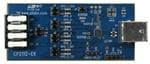
| 产品图片 |
|
| rohs | 符合RoHS无铅 / 符合限制有害物质指令(RoHS)规范要求 |
| 产品系列 | 模拟与数字IC开发工具,界面开发工具,Silicon Labs CP2112EK- |
| 数据手册 | 点击此处下载产品Datasheet点击此处下载产品Datasheet点击此处下载产品Datasheet点击此处下载产品Datasheet |
| 产品型号 | CP2112EKCP2112EK |
| 主要属性 | 全速(12Mbps) |
| 主要用途 | 接口,USB 2.0 至 SMBus 电桥 |
| 产品 | Evaluation Kits |
| 产品培训模块 | http://www.digikey.cn/PTM/IndividualPTM.page?site=cn&lang=zhs&ptm=25291http://www.digikey.cn/PTM/IndividualPTM.page?site=cn&lang=zhs&ptm=30399 |
| 产品种类 | 界面开发工具 |
| 使用的IC/零件 | CP2112 |
| 其它名称 | 336-2010 |
| 单位重量 | 50 mg |
| 商标 | Silicon Labs |
| 封装 | Bulk |
| 嵌入式 | 否 |
| 工具用于评估 | CP2112 |
| 所含物品 | 板,线缆,软件 |
| 接口类型 | I2C, SMB, USB |
| 描述/功能 | HID USB to SMB/I2C bridge |
| 标准包装 | 1 |
| 相关产品 | /product-detail/zh/CP2112-F01-GM/336-2004-5-ND/2486178 |
| 类型 | USB to SMBus |
| 系列 | CP2112 |
| 辅助属性 | LED 状态指示器 |


- 商务部:美国ITC正式对集成电路等产品启动337调查
- 曝三星4nm工艺存在良率问题 高通将骁龙8 Gen1或转产台积电
- 太阳诱电将投资9.5亿元在常州建新厂生产MLCC 预计2023年完工
- 英特尔发布欧洲新工厂建设计划 深化IDM 2.0 战略
- 台积电先进制程称霸业界 有大客户加持明年业绩稳了
- 达到5530亿美元!SIA预计今年全球半导体销售额将创下新高
- 英特尔拟将自动驾驶子公司Mobileye上市 估值或超500亿美元
- 三星加码芯片和SET,合并消费电子和移动部门,撤换高东真等 CEO
- 三星电子宣布重大人事变动 还合并消费电子和移动部门
- 海关总署:前11个月进口集成电路产品价值2.52万亿元 增长14.8%
PDF Datasheet 数据手册内容提取
CP2112-EK CP2112 EVALUATION KIT USER’S GUIDE 1. Kit Contents The CP2112 Evaluation Kit contains the following items: CP2112 Evaluation Board USB Cable DVD Quick Start Guide 2. Relevant Documentation Application notes can be found on the Interface Application Notes page for all fixed-function devices: www.silabs.com/interface-appnotes. AN721: CP210x/CP211x Device Customization Guide — Customize the VID, PID, serial number, and other parameters stored in the CP2112 one-time programmable ROM. AN496: CP2112 HID-to-SMBus API Specification — Provides function descriptions and examples for all of the PC software functions that control the CP2112. AN495: CP2112 Interface Specification — Describes the HID report format for CP2112 devices. 3. Software Setup The Software Development Kit (SDK) for the CP2112 kit is included on the kit DVD. The latest version of this installer can also be downloaded from the www.silabs.com/cp2112ek website. This package includes: Device Customization Utility Documentation — data sheet, application notes, user’s guide, quick start guide, etc. HidSmbusExample — Example software utilizing the CP2112 API interface described in AN496. Library — repackaged HID DLL and CP2112 API DLL The Windows installer should launch automatically after inserting the DVD. For Mac and Linux, browse to the appropriate directory on the DVD to install the software package. Follow the instructions to install the SDK to the system. The CP2112 is an HID device, so a driver does not need to be installed on most operating systems. Rev. 0.3 7/13 Copyright © 2013 by Silicon Laboratories CP2112-EK
CP2112-EK 4. CP2112 Hardware Interface 1. Connect the CP2112 evaluation board to a PC as shown in Figure1. 2. Connect one end of the USB cable to a USB Port on the PC. 3. Connect the other end of the USB cable to the USB connector on the CP2112 evaluation board. 4. Connect the SDA, SCL, and Ground pins on the CP2112 to an SMBus device. External pull-up resistors are not needed if the pull-up resistors on the CP2112 evaluation board are used. USB SCL CP2112 HID USB SDA SMBus/I2C to SMBus/I2C ground Device Bridge CP2112 EK Figure 1. Hardware Setup 2 Rev. 0.3
CP2112-EK 5. CP2112 Software Interface The CP2112 is an HID device that uses the standard HID functions available in the operating system. To facilitate this process in Windows, Silicon Labs packaged the standard HID functions into the SLABHIDDevice DLL in the CP2112 software package. The HID report structure for the CP2112 is customized for the device and is not compatible with other HID report structures, like a mouse or keyboard. AN495, “CP2112 Interface Specification” describes the custom HID report structure for the CP2112, and AN496, “CP2112 HID-to-SMBus API Specification” describes the API software functions that can be used to read or write data and control the CP2112 from the PC. The software application described in “6. CP2112 Windows Application” provides an example of how to use these functions. The CP2112 appears as an HID device in Device Manager as shown in Figure2. Figure 2. CP2112 in Device Manager Rev. 0.3 3
CP2112-EK 6. CP2112 Windows Application The HID SMBus Example application uses the Windows CP2112 HID-to-SMBus DLL to transmit and receive data with the CP2112. The application also has access to the CP2112’s GPIO pins. Figure3 shows a screenshot of the Windows Application. The following steps describe how to start the application and use some of its features. 1. Ensure that the hardware is connected to a Windows PC as shown in Figure1. If the device is properly connected, the red SUSPEND LED on the CP2112 evaluation board will turn on. 2. Launch the Hid SMBus Example application, which is found by clicking StartAll ProgramsSilicon LaboratoriesCP2112 Evaluation KitHidSmbus Example. 3. In this application, you can configure the SMBus settings and GPIO pins, customize the device descriptors, and read/write data over the SMBus interface. 4. Select the appropriate device in the Connection drop down box and click Connect. 5. The Configuration tab enables setting and getting the SMBus configuration parameters. To set a parameter, modify the value that is in the corresponding text box or check/uncheck a box and click Set SMBus Config. To verify that the settings took effect, click Get SMBus Config. These configuration parameters reset to their default values when the CP2112 is reset. 4 5 Figure 3. Configuring the SMBus Interface using the Example Application 4 Rev. 0.3
CP2112-EK 6. To read data from an SMBus device (non-addressed mode): a. Click the Data Transfer tab. a. Enter the slave address and the number of bytes to read in the Read Request box. b. Click the Read Request button. c. To see the number of bytes that were read back, click Get Read/Write Transfer Status and verify the number of bytes read at the bottom of the application. d. Next, click Force Read Response and then Get Read Response until the application reads back the total number of bytes. The bytes will be shown in the Received Data field. The status of the CP2112 will be shown at the bottom of the application. 6a 6b 6c 6e 6d Figure 4. Performing a Non-Addressed Read using the Example Application Rev. 0.3 5
CP2112-EK 7. To read data from an EEPROM or similar device (addressed mode): a. Click the Data Transfer tab. e. Enter the slave address, the number of address bytes in the target address, the target address of the SMBus device being read (in hex), and the number of bytes to read in the Addressed Read Request box. f. Click the Address Read Request button. g. To see the number of bytes that were read back, click Get Read/Write Transfer Status and verify the number of bytes read at the bottom of the application. h. Click Force Read Response and then Get Read Response until the application reads back the total number of bytes. The bytes will be shown in the Received Data field. The status bar of the application displays the current status of the CP2112. 7a 7b 7c 7e 7d Figure 5. Performing an Addressed Read using the Example Application 6 Rev. 0.3
CP2112-EK 8. To write data over the SMBus interface: a. Click the Data Transfer tab. i. Enter the Slave address and data (in hex) in the Write Request box. j. Click the Write Request button. k. Click Get Read/Write Transfer Status and verify that the transfer completed using the status bar at the bottom of the application. 8a 8c 8b 8d Figure 6. Performing a Write using the Example Application Rev. 0.3 7
CP2112-EK 9. The Pin Configuration tab enables configuration of the GPIO and special functions (TX Toggle, RX Toggle, and Clock Output). a. Click the Pin Configuration tab. l. GPIO pins toggle between Input/Ouput and Open-Drain/Push-Pull by clicking the corresponding GPIO boxes in the GPIO Configuration area. Check the boxes for TX Toggle, RX Toggle, and Clock Output to enable the special functionality on these pins. Click the Set GPIO Config button to update the device settings. m. The Latch Values section enables writing or reading the GPIO latches. Clicking the box next the GPIO pins listed will scroll through 1, 0, and X for a don’t care. Click the Write Latch button to change the state of the GPIO latch. 9a 9b 9c Figure 7. Configuring the CP2112 Pins using the Example Application 8 Rev. 0.3
CP2112-EK 10. The Customization tab allows for programming the One-Time-Programmable (OTP) parameters of the device. These parameters can only be programmed once and cannot be changed back to their default values after being programmed. This tab has the same functionality as the CP2112SetIDs application provided with the CP2112 software package. In order for these parameters to be sucessfully programmed, a 4.7µF capacitor must be connected between the VPP pin and ground. This capacitor is populated by default on the CP2112 Evaluation Kit board has this capacitor. See "8. Schematic" on page 12 for more information. a. The USB Customization section sets the USB parameters. Click Get to retrieve the current settings. Change the settings by modifying the text boxes and checking the box next to the parameter being modified. Click the Set button to program the device with the modified settings. The parameter will not be changed without checking the corresponding box. Perform a Get after changing any parameters to ensure that the settings updated correctly. n. The String Descriptors section enables modification of the serial strings in the CP2112. Type a string into the corresponding text box and click the Set button to modify the strings. Perform a Get after changing any parameters to ensure that the settings updated correctly. o. The Lock Byte section displays which fields have been programmed and can lock fields to prevent future modification. Any field that has been programmed will not be checked. To prevent a field from being programmed, uncheck the corresponding box and click the Set button. Perform a Get after changing any parameters to ensure that the settings updated correctly. 10a 10c 10b Figure 8. Customizing a CP2112 Device using the Example Application Rev. 0.3 9
CP2112-EK 7. Target Board The CP2112 Evaluation Kit includes an evaluation board with a CP2112 device pre-installed for evaluation and preliminary software development. Numerous input/output (I/O) connections are provided to facilitate prototyping using the evaluation board. Refer to Figure9 for the locations of the various I/O connectors. Refer to Figure10, “CP2112 Evaluation Board Schematic” for information regarding the SMBus pull-up resistors that are located on the target board. P1 USB connector for USB interface H1 Access Connector for SMBus interface (SDA, SCL, GND, Pull-Up Voltage) J1, J2, J3, J4 GPIO access connectors J6 Power connector J7 SMBus pull-up voltage connector J8 Red SUSPEND LED connector DS0–DS7 Green GPIO LEDs DS8 Red SUSPEND LED TB1 SMBus interface terminal block J4 J8 DS7 SUSPEND TB1 SILICON LABS DS6 J3 DS8 P1 GND DS5 U1 H1 DS4 SDA GND J2 CP2112 SCL EXT_PU DS3 U EXT_PU DS2 _P T J1 X O A CP2112-EK DDSS10 E VIJ7 VIO VDD+3VNET www.silabs.com SMBUSPU_V J6 Figure 9. CP2112 Evaluation Board with Default Shorting Blocks Installed 7.1. LED Headers (J1, J2, J3, J4) Connectors J1, J2, J3, and J4 are provided to allow access to the GPIO pins on the CP2112. Place shorting blocks on J1, J2, J3, and J4 to connect the GPIO pins to the eight green LEDs, DS0–DS7. These LEDs can be used to indicate active communications through the CP2112. Table1 lists the LED corresponding to each header position. Table 1. J2 and J3 LED Locations LED Pins DS0 J1[3:4] DS1 J1[1:2] DS2 J2[3:4] DS3 J2[1:2] DS4 J3[3:4] DS5 J3[1:2] DS6 J4[3:4] DS7 J4[1:2] 10 Rev. 0.3
CP2112-EK 7.2. Universal Serial Bus (USB) Interface (P1) A Universal Serial Bus (USB) connector (P1) is provided to facilitate connections to the USB interface on the CP2112. See Table2 for the USB pin definitions. Table 2. USB Connector Pin Descriptions Pin # Description 1 VBUS 2 D- 3 D+ 4 GND (Ground) 7.3. SMBus Signals (TB1, H1) The SMBus interface terminal block and access headers are included to easily interace SMBus devices to the evaluation board. The terminal block can be used to connect wires to the board, and the access connectors can be used to connect scope probes to the SMBus interface for debugging. The signals that are accessible through these two connectors are SDA, SCL, GND, and the external pull-up voltage signal. 7.4. VDD and VIO Power Connector (J6) This header (J6) is included on the evaluation board to provide several power options. The following describes the function of each pin: Pins 1–2: Connect CP2112 VIO input (pin 5) to CP2112 VDD (Pin 6). Remove the shorting block to power VIO from an external source. Pins 3–4: Connects the main +3V net to the CP2112 VDD (Pin 6). The main +3V net powers the other components (eight green LEDs) on the board. 7.5. SMBus Pull-Up Voltage Connector (J7) This header (J7) is included on the evaluation board to provide power options for SMBus pull-up voltage. The following describes the function of each pin: J7[1:2]: Connects CP2112 VIO pin (Pin 5) to the 4.7k pull-up resistors located on the evaluation board. J7[2:3]: Connects the External Pull-Up signal from TB1 (Pin 4) to the 4.7kpull-up resistors on the evaluation board. 7.6. SUSPEND LED Connector (J8) The J8 header is used to connect the CP2112 SUSPEND pin (Pin 17) to the DS8 red LED. When the LED is on, the device has enumerated with the PC operating normally. When the LED is off, the device has not yet enumerated or is in the USB Suspend state. Rev. 0.3 11
CP2112-EK 8. Schematic c i t a m e h c S d r a o B n o i t a u l a v E 2 1 1 2 P C . 0 1 e r u g i F 12 Rev. 0.3
CP2112-EK DOCUMENT CHANGE LIST Revision 0.1 to Revision 0.2 Updated Figure1. Updated "6. CP2112 Windows Application" on page 4. Instructions and figures from updated PC application. Updated Figure10 on page 12. Revision 0.2 to Revision 0.3 Updated “1. Kit Contents” to change CD-ROM to DVD. Added “2. Relevant Documentation” and “5. CP2112 Software Interface”. Updated “3. Software Setup” to point to the drivers on the website. Updated Figure1. Updated the instructions and figures in “6. CP2112 Windows Application”. 13 Rev. 0.3
Simplicity Studio One-click access to MCU and wireless tools, documentation, software, source code libraries & more. Available for Windows, Mac and Linux! IoT Portfolio SW/HW Quality Support and Community www.silabs.com/IoT www.silabs.com/simplicity www.silabs.com/quality community.silabs.com Disclaimer Silicon Labs intends to provide customers with the latest, accurate, and in-depth documentation of all peripherals and modules available for system and software implementers using or intending to use the Silicon Labs products. Characterization data, available modules and peripherals, memory sizes and memory addresses refer to each specific device, and "Typical" parameters provided can and do vary in different applications. Application examples described herein are for illustrative purposes only. Silicon Labs reserves the right to make changes without further notice and limitation to product information, specifications, and descriptions herein, and does not give warranties as to the accuracy or completeness of the included information. Silicon Labs shall have no liability for the consequences of use of the information supplied herein. This document does not imply or express copyright licenses granted hereunder to design or fabricate any integrated circuits. The products are not designed or authorized to be used within any Life Support System without the specific written consent of Silicon Labs. A "Life Support System" is any product or system intended to support or sustain life and/or health, which, if it fails, can be reasonably expected to result in significant personal injury or death. Silicon Labs products are not designed or authorized for military applications. Silicon Labs products shall under no circumstances be used in weapons of mass destruction including (but not limited to) nuclear, biological or chemical weapons, or missiles capable of delivering such weapons. Trademark Information Silicon Laboratories Inc.® , Silicon Laboratories®, Silicon Labs®, SiLabs® and the Silicon Labs logo®, Bluegiga®, Bluegiga Logo®, Clockbuilder®, CMEMS®, DSPLL®, EFM®, EFM32®, EFR, Ember®, Energy Micro, Energy Micro logo and combinations thereof, "the world’s most energy friendly microcontrollers", Ember®, EZLink®, EZRadio®, EZRadioPRO®, Gecko®, ISOmodem®, Precision32®, ProSLIC®, Simplicity Studio®, SiPHY®, Telegesis, the Telegesis Logo®, USBXpress® and others are trademarks or registered trademarks of Silicon Labs. ARM, CORTEX, Cortex-M3 and THUMB are trademarks or registered trademarks of ARM Holdings. Keil is a registered trademark of ARM Limited. All other products or brand names mentioned herein are trademarks of their respective holders. Silicon Laboratories Inc. 400 West Cesar Chavez Austin, TX 78701 USA http://www.silabs.com
Mouser Electronics Authorized Distributor Click to View Pricing, Inventory, Delivery & Lifecycle Information: S ilicon Laboratories: CP2112EK