ICGOO在线商城 > VVA9C00-000
 Datasheet下载
- 型号: VVA9C00-000
- 制造商: Carling Technologies
- 库位|库存: xxxx|xxxx
- 要求:
| 数量阶梯 | 香港交货 | 国内含税 |
| +xxxx | $xxxx | ¥xxxx |
查看当月历史价格
查看今年历史价格
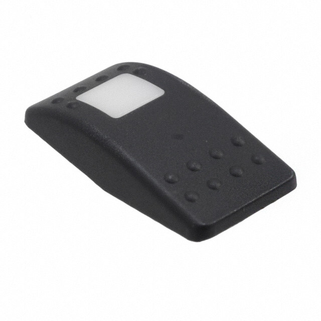
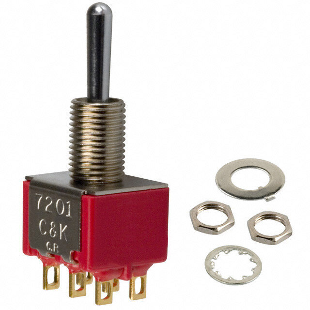
VVA9C00-000产品简介:
ICGOO电子元器件商城为您提供VVA9C00-000由Carling Technologies设计生产,在icgoo商城现货销售,并且可以通过原厂、代理商等渠道进行代购。 提供VVA9C00-000价格参考¥3.83-¥6.29以及Carling TechnologiesVVA9C00-000封装/规格参数等产品信息。 你可以下载VVA9C00-000参考资料、Datasheet数据手册功能说明书, 资料中有VVA9C00-000详细功能的应用电路图电压和使用方法及教程。
| 参数 | 数值 |
| 产品目录 | |
| 描述 | CAP ROCKER RECT BLK/WHT LENS |
| 产品分类 | |
| 品牌 | Carling Technologies |
| 数据手册 | |
| 产品图片 |
|
| 产品型号 | VVA9C00-000 |
| rohs | 无铅 / 符合限制有害物质指令(RoHS)规范要求 |
| 产品系列 | V |
| 其它名称 | 432-1306 |
| 安装类型 | 卡入式 |
| 尺寸 | 49.09mm 长 x 23.88mm 宽 x 12.83mm 高 |
| 开关类型 | 摇臂 |
| 形状 | 矩形,凸起(圆顶) |
| 标准包装 | 100 |
| 照明 | 发光开口 |
| 特性 | - |
| 配套使用产品/相关产品 | V 系列 |
| 配用 | /product-detail/zh/V1D2GHNB-00000-000/V1D2GHNB-00000-000-ND/2329065/product-detail/zh/V6D1D66B-00000-000/432-1299-ND/3025009/product-detail/zh/VJD1D66B-00000-000/432-1303-ND/3025025/product-detail/zh/VLD1A60B-00000-000/432-1304-ND/3025030/product-detail/zh/V1D1G66B-00000-000/432-1294-ND/3025051/product-detail/zh/V2D1A60B-00000-000/432-1297-ND/3025059/product-detail/zh/V2D1160B-00000-000/432-1296-ND/3025084 |
| 颜色 | 黑色,白色透镜 |


- 商务部:美国ITC正式对集成电路等产品启动337调查
- 曝三星4nm工艺存在良率问题 高通将骁龙8 Gen1或转产台积电
- 太阳诱电将投资9.5亿元在常州建新厂生产MLCC 预计2023年完工
- 英特尔发布欧洲新工厂建设计划 深化IDM 2.0 战略
- 台积电先进制程称霸业界 有大客户加持明年业绩稳了
- 达到5530亿美元!SIA预计今年全球半导体销售额将创下新高
- 英特尔拟将自动驾驶子公司Mobileye上市 估值或超500亿美元
- 三星加码芯片和SET,合并消费电子和移动部门,撤换高东真等 CEO
- 三星电子宣布重大人事变动 还合并消费电子和移动部门
- 海关总署:前11个月进口集成电路产品价值2.52万亿元 增长14.8%


PDF Datasheet 数据手册内容提取
V-Series V-Series CONTURA SWITCHES Carling Technologies’ sealed V-Series Contura switches are well known for their cutting edge design, high quality, maximum performance and unmatched reliability. These switches are a staple in the marine and transportation industries and have passed a range of environmental, corrosion, temperature, vibration, shock and sealing tests including MIL Std 202F, MIL Std 510.1, UL 1500, ISO 8846, IEC 60529 and BS 5490 among others, making them one of the most rugged and reliable switches ever manufactured. Resources: Configure a Complete Part Download CAD & Sales Drawing Watch Product Video Product Highlights: Typical Applications: • Sealed to IP66/68 for Above-Panel Components • Marine Panels • Silver plated butt contact mechanism provides • Emergency Vehicles reliability up to and beyond 100K electrical cycles • Trucks • Greaseless construction withstands temperature • Buses extremes down to -40˚C • Construction Equipment • The switch accommodates up to 10 terminals and • Motorcycles & ATVs endless illumination and circuit options. • Farm Equipment • The switch connector allows the user to preload • Commercial Appliances FQC terminals for ease of assembly. • Military Vehicles • Numerous choices of removable rockers allow for • Mining Equipment style change without having to retest or re-qualify • Golf Carts the switch base. • Floor Cleaning Equipment • Utility Vehicles Carling Technologies, Inc. 60 Johnson Avenue, Plainville, CT 06062 Email: sales@carlingtech.com www.carlingtech.com Application Support: team2@carlingtech.com Phone: 860.793.9281 Fax: 860.793.9231
2 | V-Series - Contura® Sealed Rocker Switches - Design Features V-Series Switch DESIGN FEATURES INTERCHANGEABLE ACTUATORS DUAL SEAL PROTECTION CLEAN CONNECTIONS Panel redesign is a snap with our wide Seals out water, dust, debris, Options for both eight and ten range of rocker styles. Achieve maximum and sealed to IP66/68 for terminal base styles with AMP & design variety with minimum inventory. above-panel components Packard compatible connectors Simply swap rockers to create an entirely affords myriad circuit options new look for your panel. while providing ease of assembly. OPTIONAL PANEL SEAL MULTIPLE LIGHTING OPTIONS BRASS ROLLER PIN SILVER PLATED BUTT Helps prevent water/dust In addition to Incandescent Robust mechanism CONTACT MECHANISM ingress behind panel. lamps, our LED illumination is eliminates the need for Providing 50k to 100k offered in a wide array of light lubricants. Enables switch electrical cycles, circuit and intensities, colors, as well as to withstand -40°C to load dependent dual level, tri-color, and flashing +85°C temperatures. options. *Manufacturer reserves the right to change product specification without prior notice. Email: sales@carlingtech.com Application Support: team2@carlingtech.com Phone: (860) 793–9281 Fax: (860) 793–9231 www.carlingtech.com
3 | V-Series - Contura® Sealed Rocker Switches - Actuator Options & Accessories Contura II & III Contura X The Contura II & III actuators are The raised bracket/bezel on the constructed of thermoplastic Contura X helps prevent inadvertent polycarbonate and are offered with actuation of the rocker, as well as a hard nylon overlay or a “soft-touch” preventing debris from being trapped elastomer overlay. These models under the actuator. This curved rocker incorporate aesthetic designs on style is available with a variety of the top and bottom of the rocker lenses and legends. featuring two rows of raised “bumps” on the Contura II and three “indented” lines on the Contura III. Contura IV Contura XI The Contura IV’s “Shape to create The raised bracket/bezel on the a Shape” actuator works with the Contura XI helps prevent inadvertent curves, contours & advanced styling actuation of the rocker, as well as of the latest panel designs, flowing preventing debris from being trapped with these advanced curves & radii. under the actuator. This convex style This actuator style fits on the Contura rocker is available with a wide variety flush bracket/bezel. of lenses and legends. Contura V Contura XII The symmetrically curved Contura The Contura XII version features a V actuator provides the perfect paddle style actuator with the raised complement to the Contura IV’s bracket/bezel of Contura X and XI. The “Shape to create a Shape” design contoured handle design provides concept. With its flush style mounting intuitive recognition and ease of bracket, Contura V can be mounted in operation and is available with all between two Contura IV’s, by itself, or Contura X and XI lens and legend in groups. offerings. Contura VI (WAVE) Contura XIV The Contura VI WAVE sealed rocker The Contura XIV represents a sleek new switches, when used in a row, create crossover rocker design which should an uniquely appealing “wave” design appeal to Trucks, Buses and Heavy on your panel. A variety of colors and Vehicles as well as the Marine Industry. finishes are available for both rocker Intuitive feel is provided by recessed and wave insert. Contura VI features ridges along with a Center Groove bar and oval lenses. which effectively defines the boundary between top and bottom switch functions. Contura VII Illuminated Indicators Contura VII featuring gently & Accessories curved corners and edges assuring Alert operator of systems functions compatibility with most any panel or malfunctions, are offered with design. Intuitive feel is maximized removable/replaceable lamps in by the use of 2 embossed circular Contura II, II, V or X styles. Accessories pads located at opposite ends of include connectors, mounting panels, the rocker. Any combination of Bar hole plugs, panel seals, and actuator or Oval style lenses can be located removal tools. Refer to accessories page in the pads providing a truly unique for full details look, exclusive to Contura VII. Email: sales@carlingtech.com Application Support: team2@carlingtech.com Phone: (860) 793–9281 Fax: (860) 793–9231 www.carlingtech.com
4 | V-Series - Contura® Sealed Rocker Switches - General Specifications Electrical Agency Certifications Contact Rating .4VA @ 24VDC (MAX) resistive 15 amps, 125VAC 10 amps, 250VAC 1/2 HP 125-250VAC 20 amps, 4-14VDC 15 amps, 15-28VDC Environmental 10A, 14VT Sealing IP66/68, for above-panel components 6A, 125VAC L of actual switch only. Dielectric Strength 1500 Volts RMS Corrosion Mixed Flowing Gas (MFG) Class III Insulation Resistance 50 Megohms 3 year accelerated exposure per ASTM B-827, B-845 Silver and gold Initial Contact Resistance 10 milliohms max. @ 4VDC contacts Life Up to 100,000 cycles, circuit Operating Temp. -40°C to +85°C and load dependent Vibration 1 Per Mil-Std 202F, Method 204D Contacts Silver alloy, silver tin-oxide, fine Test Condition A 0.06 DA or 10G’s silver 10-500 Hz. Tested with VCH connector. Terminals Brass or copper/silver plate 1/4” Test criteria - No loss of circuit during (6.3mm) Quick Connect test, pre and post test contact terminations standard. Solder lug, resistance. Wire Lead Vibration 2 Resonance search 24-50 Hz 0.40 DA 50-2000 Hz ±10 G’s peak Physical Horizontal Axis 3-5 G’s max. Lighted Incandescent - rated 10,000 Random hours Neon - rated 25,000 hours 24 Hz 0.06 PSD-Gsq/Hz LED - rated 100,000 hours 1/2 life 60 Hz 0.50 (LED is internally ballasted for 100 Hz 0.50 voltages to 24VDC) 200 Hz 0.025 Seals Internal 2000 Hz 0.025 No loss of circuit during test; <10μ Optional external gasket panel seal seconds chatter. Base Polyester blend rated to 125°C with Shock Per Mil-Std 202F, Method 213B, Test a UL flammability rating of 94V0. Condition K @ 30G’s. Tested with Contura II,III,IV,V, Hard Surface: Basic actuator VCH connector. Test criteria - No loss VI, VII Actuator structure molded of thermoplastic of circuit during test, pre and post polycarbonate with a hard Nylon 66 test contact resistance. thermoplastic surface overlay. Salt Spray Per Mil-Std 202F, Method 101D, Test Soft Surface: Basic actuator structure Condition A, 96 Hrs. Sealed version only. molded of thermoplastic polycarbonate Dust Mil STD 810, Method 510.2 Air Velocity with an elastomer overlay. 300 Ft/Min Duration 16Hr Thermal Shock Per Mil-Std 202F, Method 107F, Test Contura X,XI,XII Actuator,VP Nylon 66 Reinforced rated to 105°C Cond. A, -55°C to +85°C. Test criteria - Lens Polycarbonate rated at 100°C pre and post test contact resistance Contura XIV Polycarbonate lens/sub-rocker with Moisture Resistance Per Mil-Std 202F, Method 106F, Test ABS shell Criteria - pre and post test contact resistance Actuator Travel (Angular Displacement) Ignition Protection All Contura switches with sealed 2 position 18° construction meet the requirements of UL1500/ISO8846 for ignition 3 positions 9° from center protection, in addition to conformance with EC directive Mounting Specifications .830[21.08] 94/25/EC for marine products. Panel Thickness Range Gaskets Acceptable Panel Thickness TEST CUT 0 .030 to .250 (.76 to 6.35mm) 1.450[36.83] HOLE IN ACTUAL 1 .030 to .109 & .147 to .157 MATERIAL (.76 to 2.77mm & 3.73 to 3.98mm) Recommended: No gasket with panel SWITCH thickness of .032, .062, .093, .125,.187 or .250 MOUNTING HOLE Email: sales@carlingtech.com Application Support: team2@carlingtech.com Phone: (860) 793–9281 Fax: (860) 793–9231 www.carlingtech.com
5 | V-Series - Contura® Sealed Rocker Switches - Contura II & III - Ordering Scheme V 1 D A B T 0 B A R B 00 0 00 1 2 3 4 5 6 7 8 9 10 11 12 13 14 Series Circuit Rating TerminationIllumination Lamp Lamp Bracket Actuator Lens Color Legend Legend Actuator Orientation Lens Legend 1 SERIES 6,7 LAMP (SAME CODING FOR BOTH SELECTIONS) V Selection 6: above terminals 1 & 4; Selection 7: above terminals 3 & 6 No lamp 0 Neon 1 125VAC 2 250VAC 2 CIRCUIT Incandescent 4 3V 5 6V 6 12V 7 18V 8 24V Terminal Connections as viewed ( ) - momentary LED* superbright superbright from bottom of switch: SP - single pole - uses terminals 1, 2 & 3. Red Amber Green Red 2VDC A L F R 8 terminal 10 terminal DP - double pole uses terminals 1, 2, 3, 4, 5 & 6. 6VDC B M G S 8 - - 7 8 - - 7 Terminals 7, 8, 9 & 10 for lamp circuit only. 12VDC C N H T 1 - - 4 1 - - 4 24VDC D P J V 2 - - 5 2 - - 5 * Consult factory for “daylight bright” LED options. Typical current draw for 3 - - 6 3 - - 6 LED is 20ma. 10 - - 9 Position: 1 2 3 SP DP 2 & 3, 5 & 6 Connected Terminals 1 & 2, 4 & 5 8 FLUSH BRACKET COLOR 1, PANEL SEAL 1 A ON NONE OFF Black White Gray 2 B (ON) NONE OFF No Seal B W G 3 C ON NONE (OFF) One Seal C Y H 4 D ON NONE ON 5 F ON NONE (ON) 6 J ON OFF ON 9 ACTUATOR 7 K ON OFF (ON) 0 No Actuator 8 L (ON) OFF (ON) A, B Contura II SPECIAL CIRCUITS C, D Contura III H* 2 & 3 2 & 3, 5 & 4 5 & 4 G* 2 & 3, 5 & 6 2 & 3 OFF Actuator thick end over terminals: 3,6 1,4 S* 2 & 3, 5 & 6 2 & 3 1 & 2 M* (2 & 3, 5 & 6) 2 & 3 OFF R* (2 & 3, 5 & 6) 2 & 3 2 & 1 E* 5 & 6 5 & 3 5 & 1 10 LENS 0 - No Actuator Z - No Lens *Jumper between terminals 2 & 5 for circuits H,G,M,R & S are specified in Clear White Amber Green Red Blue selection 4. External jumper between terminals 2 & 4 for circuit E are provided by customer. Circuit E may be used for SP OFF-ON-ON circuit. 1 6 8 G M T 2 7 C H N U 3 8 D J P V 3 RATING 3 Square lens options only available for Contura II. 1 .4VA @ 28VDC Resistive 4 9 E K R W B 15A 24V 5 A F L S Y C 20A 18V Lens color for LEDs must be clear, white, or match color of LED. D 20A 12V Green or blue lenses are not recommended with Neon lamps. E 20A 14V, 10A 14VT (circuit 1, 4 , A & D only) F 10A 14V, 6A 14VT (circuit G only) MN ..44VVAA//2105AA 1224VV 11 ACTUATOR COLOR 1 AND TEXTURE 0 - No Actuator Black Gray Red White 4 TERMINATION / BASE STYLE Soft Surface B G R W 8 term 10 Term Termination Jumper Hard Surface C H S Y 1 2 .250 TAB (QC) no barriers No A B .250 TAB (QC) with barriers No J K .250 TAB (QC) no barriers Yes T2 to 5 12 ACTUATOR LENS OR BODY LEGENDS 2 3 5 Solder Lug no barriers No 11 ON 12 OFF 13 I 14 O C D Solder Lug No OFF ON O I 5 6 Wire Leads no barriers No 15 O O 16 O O 17 O I 18 I O E F Wire Leads No F N N F Note: Codes J & K for circuits H, G & M. Do not use silicone based F F lubricants to reduce terminal insertion forces during connector assembly, For additional legend options & codes, visit us at www.carlingtech.com. as it is detrimental to function and performance. 13 LEGEND ORIENTATION 5 ILLUMINATION 0 No legend (used with codes 11-18 in selection 12) Lamp #1:above terminals 1 & 4 end of switch.; Lamp #2 above terminals 1 Orientation 1 3 & 6 end of switch. Positive (+) and negative (-) symbols apply to LED 2 Orientation 2 lamps only 3 Orientation 3 Sealed Unsealed Lamps Illumination Type Lamp wired to Terminals 4 Orientation 4 S 0 NONE – – A 1 1 INDEPENDENT 8 (+) 7 (–) B 2 1 DOWN 3 (+) 7 (–) C 3 2 UP 3 (+) 7 (–) 1 2 3 4 D 4 1 DOWN 3 (+) 7 (–) 2 DOWN 1 (+) 7 (–) E 5 1 UP 1 (+) 7 (–) 2 UP 3 (+) 7 (–) 14 ACTUATOR LENS LEGEND F 6 1 INDEPENDENT 8 (+) 7 (–) 00 No legend this location / no actuator 2 UP 3 (+) 6 (–) (used with codes 11-18 in selection 12) Selection 14 required when switch G 7 1 INDEPENDENT 8 (+) 7 (–) requires two legends. If the two legends consist of one lens and one body legend, lens legend must be specified in selection 12; body legend 2 UP 3 (+) 7 (–) specified in selection 14. H Z 2 INDEPENDENT 8 (+) 7 (–) For legend options & codes, visit us at www.carlingtech.com. U Y 1 INDEPENDENT 8 (+) 7 (–) 2 INDEPENDENT 10 (+) 9 (–) Notes: SINGLE POLE SWITCHES ONLY Consult factory to verify horsepower rating for your particular circuit choice. J 8 1 DOWN 3 (+) 8 (–) 1 Custom colors are available. Consult factory. 2 INDEPENDENT 6 (+) 7 (–) 2 Body legends not available on Soft surface actuators; White imprinting is standard K W 1 INDEPENDENT 8 (+) 7 (–) on black actuators; Black imprinting is standard on white, red and gray actuators. 2 INDEPENDENT 6 (+) 7 (–) Custom colors are available, consult factory. DOUBLE POLE SWITCHES ONLY 3 Additional ratings available. See V-Series Switch Accessories page. L 9 1 DOWN 3 (+) 6 (–) 4 Contura II available with two square lenses. Consult factory for details. M R 1 UP 3 (+) 6 (–) N T 1 DOWN 3 (+) 6 (–) 2 DOWN 1 (+) 4 (–) P V 1 UP 1 (+) 4 (–) 2 UP 3 (+) 6 (–) Email: sales@carlingtech.com Application Support: team2@carlingtech.com Phone: (860) 793–9281 Fax: (860) 793–9231 www.carlingtech.com
6 | V-Series - Contura® Sealed Rocker Switches - Contura II & III Locking - Ordering Scheme V 1 D A S W 0 B A Z E 00 0 1 2 3 4 5 6 7 8 9 10 11 12 13 Series Circuit Rating TerminationIllumination Lock Lamp Bracket Actuator Lens Function Legend Legend Orientation 1 SERIES 7 LAMP V Lamp above terminals 3 & 6 end of switch No lamp 0 Neon 1 125VAC 2 250VAC 2 CIRCUIT Incandescent 4 3V 5 6V 6 12V 7 18V 8 24V LED* superbright superbright Terminal Connections as viewed ( ) - momentary Red Amber Green Red from bottom of switch: SP - single pole - uses terminals 1, 2 & 3. 2VDC A L F R 8 terminal 10 terminal DP - double pole uses terminals 1, 2, 3, 4, 5 & 6. 6VDC B M G S 8 - - 7 8 - - 7 Terminals 7, 8, 9 & 10 for lamp circuit only. 12VDC C N H T 1 - - 4 1 - - 4 24VDC D P J V 2 - - 5 2 - - 5 * Consult factory for “daylight bright” LED options. Typical current draw for LED is 20ma. 3 - - 6 3 - - 6 10 - - 9 Position: 1 2 3 SP DP 2 & 3, 5 & 6 Connected Terminals 1 & 2, 4 & 5 8 FLUSH BRACKET COLOR 1, PANEL SEAL 1 A ON NONE OFF Black White Gray 4 D ON NONE ON No Seal B W G 6 J ON OFF ON One Seal C Y H 7 K ON OFF (ON) 8 L (ON) OFF (ON) 9 N OFF NONE ON 9 HARD SURFACE ACTUATOR 1 SPECIAL CIRCUITS Black Gray Red White H* 2 & 3 2 & 3, 5 & 4 5 & 4 Contura II A B G H G* 2 & 3, 5 & 6 2 & 3 OFF S* 2 & 3, 5 & 6 2 & 3 1 & 2 Contura III C D E F M* (2 & 3, 5 & 6) 2 & 3 OFF R* (2 & 3, 5 & 6) 2 & 3 2 & 1 Actuator orientation above terminals: 3,6 1,4 E* 5 & 6 5 & 3 5 & 1 *Jumper between terminals 2 & 5 for circuits H,G,M,R & S are specified in selection 4. External jumper between terminals 2 & 4 for circuit E are 10 LENS provided by customer. Circuit E may be used for SP OFF-ON-ON circuit. Z - No Lens Clear White Amber Green Red Blue 3 8 D J P V 3 RATING 4 1 .4VA @ 28VDC Resistive Lens color for LEDs must be clear, white, or match color of LED. B 15A 24V Green or blue lenses are not recommended with Neon lamps. C 20A 18V D 20A 12V E 20A 14V, 10A 14VT (circuit 1, 4 , A & D only) 11 ACTUATOR LOCK FUNCTION AND COLOR 1 F 10A 14V, 6A 14VT (circuit G only) Lock Color Up Down Up & Down Center 3 M .4VA/20A 12V Match Actuator A H R 1 N .4VA/15A 24V Black B J S 2 White C K T 3 Red D L V 4 4 TERMINATION / BASE STYLE Safety Orange E M W 5 8 term 10 Term Termination Jumper 1 2 .250 TAB (QC) no barriers No A B .250 TAB (QC) with barriers No 12 ACTUATOR LENS OR BODY LEGEND 2 J K .250 TAB (QC) no barriers Yes T2 to 5 00 - No Legend 3 5 Solder Lug no barriers No 21 22 23 24 C D Solder Lug No 5 6 Wire Leads no barriers No OFF ON O I E F Wire Leads No 25 O 26 O 27 O 28 I Note: Codes J & K for circuits H, G & M. Do not use silicone based F N lubricants to reduce terminal insertion forces during connector assembly, F as it is detrimental to function and performance. For additional legend options & codes, visit us at www.carlingtech.com. 13 LEGEND ORIENTATION 5 ILLUMINATION & SWITCH SEALING Lamp #1:above terminals 1 & 4 end of switch.; Lamp #2 above terminals 0 No legend (used with codes 21-28 in selection 12) 3 & 6 end of switch. Positive (+) and negative (-) symbols apply to LED 1 Orientation 1 lamps only 2 Orientation 2 Sealed Unsealed Lamps Illumination Type Lamp wired to Terminals 3 Orientation 3 S 0 NONE – – 4 Orientation 4 C 3 2 UP 3 (+) 7 (–) 1 2 3 4 H Z 2 INDEPENDENT 8 (+) 7 (–) DOUBLE POLE SWITCHES ONLY M R 1 UP 3 (+) 6 (–) 6 LOCK Lock above terminals 1 & 4 end of switch W lock Notes: Consult factory to verify horsepower rating for your particular circuit choice. 1 Custom colors are available. Consult factory. 2 White imprinting is standard on black actuators; Black imprinting is standard on white, red and gray actuators. Custom colors are available, consult factory. 3 Only available with 3 position circuits. Center OFF and special circuits only available with center position lock function. 4 Additional ratings available. See V-Series Switch Accessories page. Email: sales@carlingtech.com Application Support: team2@carlingtech.com Phone: (860) 793–9281 Fax: (860) 793–9231 www.carlingtech.com
7 | V-Series - Contura® Sealed Rocker Switches - Contura IV - Ordering Scheme V 1 D A B T 0 B E P C 00 0 00 1 2 3 4 5 6 7 8 9 10 11 12 13 14 Series Circuit Rating TerminationIllumination Lamp Lamp Bracket Actuator Lens Color Legend Legend Actuator Orientation Lens Legend 1 SERIES 6,7 LAMP (SAME CODING FOR BOTH SELECTIONS) V Selection 6: above terminals 1 & 4; Selection 7: above terminals 3 & 6 No lamp 0 Neon 1 125VAC 2 250VAC 2 CIRCUIT Incandescent 4 3V 5 6V 6 12V 7 18V 8 24V Terminal Connections as viewed ( ) - momentary LED* superbright superbright from bottom of switch: SP - single pole - uses terminals 1, 2 & 3. Red Amber Green Red 2VDC A L F R 8 terminal 10 terminal DP - double pole uses terminals 1, 2, 3, 4, 5 & 6. 6VDC B M G S 8 - - 7 8 - - 7 Terminals 7, 8, 9 & 10 for lamp circuit only. 12VDC C N H T 1 - - 4 1 - - 4 24VDC D P J V 2 - - 5 2 - - 5 * Consult factory for “daylight bright” LED options. Typical current draw for 3 - - 6 3 - - 6 LED is 20ma. 10 - - 9 Position: 1 2 3 SP DP 2 & 3, 5 & 6 Connected Terminals 1 & 2, 4 & 5 8 FLUSH BRACKET COLOR 1, PANEL SEAL 1 A ON NONE OFF Black White Gray 2 B (ON) NONE OFF No Seal B W G 3 C ON NONE (OFF) One Seal C Y H 4 D ON NONE ON 5 F ON NONE (ON) 6 J ON OFF ON 9 ACTUATOR 1,4 7 K ON OFF (ON) 0 No Actuator 8 L (ON) OFF (ON) E Contura IV, left orientation SPECIAL CIRCUITS T Contura IV, left orientation, laser etched H* 2 & 3 2 & 3, 5 & 4 5 & 4 F Contura IV, right orientation G* 2 & 3, 5 & 6 2 & 3 OFF R Contura IV, right orientation, laser etched S* 2 & 3, 5 & 6 2 & 3 1 & 2 Actuator orientation over terminals: 3,6 M* (2 & 3, 5 & 6) 2 & 3 OFF R* (2 & 3, 5 & 6) 2 & 3 2 & 1 E* 5 & 6 5 & 3 5 & 1 10 LENS *Jumper between terminals 2 & 5 for circuits H,G,M,R & S are specified in 0 - No Actuator Z - No Lens selection 4. External jumper between terminals 2 & 4 for circuit E are Clear White Amber Green Red Blue provided by customer. Circuit E may be used for SP OFF-ON-ON circuit. 1 6 8 G M T 2 7 C H N U 3 8 D J P V 3 RATING 4 4 9 E K R W 1 .4VA @ 28VDC Resistive 5 A F L S Y B 15A 24V E F C 20A 18V Lens color for LEDs must be clear, white, or match color of LED. D 20A 12V Green or blue lenses are not recommended with Neon lamps. E 20A 14V, 10A 14VT (circuit 1, 4 , A & D only) F 10A 14V, 6A 14VT (circuit G only) M .4VA/20A 12V 11 ACTUATOR COLOR 1,5,6 N .4VA/15A 24V No Actuator 0 Black C Gray H Red S White Y Nickel D Pewter E 4 TERMINATION / BASE STYLE 8 term 10 Term Termination Jumper 12 ACTUATOR LENS OR BODY LEGENDS 2 1 2 .250 TAB (QC) no barriers No A B .250 TAB (QC) with barriers No 11 ON 12 OFF 13 I 14 O J K .250 TAB (QC) no barriers Yes T2 to 5 OFF ON O I 3 5 Solder Lug no barriers No 15 O O 16 O O 17 O I 18 I O C D Solder Lug No F N N F 5 6 Wire Leads no barriers No F F E F Wire Leads No Note: Codes J & K for circuits H, G & M. Do not use silicone based For additional legend options & codes, visit us at www.carlingtech.com. lubricants to reduce terminal insertion forces during connector assembly, as it is detrimental to function and performance. 13 LEGEND ORIENTATION 0 No legend (used with codes 11-18 in selection 12) 1 Orientation 1 5 ILLUMINATION & SWITCH SEALING 2 Orientation 2 Lamp #1:above terminals 1 & 4 end of switch.; Lamp #2 above terminals 3 Orientation 3 3 & 6 end of switch. Positive (+) and negative (-) symbols apply to LED 4 Orientation 4 lamps only 1 2 3 4 Sealed Unsealed Lamps Illumination Type Lamp wired to Terminals S 0 NONE – – A 1 1 INDEPENDENT 8 (+) 7 (–) B 2 1 DOWN 3 (+) 7 (–) 14 ACTUATOR LENS LEGEND C 3 2 UP 3 (+) 7 (–) 00 No legend this location / no actuator D 4 1 DOWN 3 (+) 7 (–) (used with codes 11-18 in selection 12) Selection 14 required when switch requires two legends. If the two legends consist of one lens and one 2 DOWN 1 (+) 7 (–) body legend, lens legend must be specified in selection 12; body legend E 5 1 UP 1 (+) 7 (–) specified in selection 14. 2 UP 3 (+) 7 (–) For legend options & codes, visit us at www.carlingtech.com. F 6 1 INDEPENDENT 8 (+) 7 (–) 2 UP 3 (+) 6 (–) G 7 1 INDEPENDENT 8 (+) 7 (–) Notes: 2 UP 3 (+) 7 (–) Consult factory to verify horsepower rating for your particular circuit choice. H Z 2 INDEPENDENT 8 (+) 7 (–) 1 Custom colors are available. Consult factory. U Y 1 INDEPENDENT 8 (+) 7 (–) 2 White imprinting is standard on black actuators; Black imprinting is standard on white, 2 INDEPENDENT 10 (+) 9 (–) red and gray actuators. Custom colors are available, consult factory. SINGLE POLE SWITCHES ONLY 3 Gloss brow is on left side of E actuator and right side of F actuator. J 8 1 DOWN 3 (+) 8 (–) 4 Additional ratings available. See V-Series Switch Accessories page. 2 INDEPENDENT 6 (+) 7 (–) 5 Laser etched rocker only available with lens code Z & actuator colors black, K W 1 INDEPENDENT 8 (+) 7 (–) nickel or pewter. 6 Pewter and nickel colors only available with laser etched actuator. 2 INDEPENDENT 6 (+) 7 (–) DOUBLE POLE SWITCHES ONLY L 9 1 DOWN 3 (+) 6 (–) M R 1 UP 3 (+) 6 (–) N T 1 DOWN 3 (+) 6 (–) 2 DOWN 1 (+) 4 (–) P V 1 UP 1 (+) 4 (–) 2 UP 3 (+) 6 (–) Email: sales@carlingtech.com Application Support: team2@carlingtech.com Phone: (860) 793–9281 Fax: (860) 793–9231 www.carlingtech.com
8 | V-Series - Contura® Sealed Rocker Switches - Contura V - Ordering Scheme V 1 D A B T 0 B G P C 00 0 00 1 2 3 4 5 6 7 8 9 10 11 12 13 14 Series Circuit Rating TerminationIllumination Lamp Lamp Bracket Actuator Lens Color Legend Legend Actuator Orientation Lens Legend 1 SERIES 6,7 LAMP (SAME CODING FOR BOTH SELECTIONS) V Selection 6: above terminals 1 & 4; Selection 7: above terminals 3 & 6 No lamp 0 Neon 1 125VAC 2 250VAC 2 CIRCUIT Incandescent 4 3V 5 6V 6 12V 7 18V 8 24V Terminal Connections as viewed ( ) - momentary LED* superbright superbright Red Amber Green Red from bottom of switch: SP - single pole - uses terminals 1, 2 & 3. 2VDC A L F R 8 terminal 10 terminal DP - double pole uses terminals 1, 2, 3, 4, 5 & 6. 6VDC B M G S 8 - - 7 8 - - 7 Terminals 7, 8, 9 & 10 for lamp circuit only. 12VDC C N H T 1 - - 4 1 - - 4 24VDC D P J V 2 - - 5 2 - - 5 * Consult factory for “daylight bright” LED options. Typical current draw for 3 - - 6 3 - - 6 LED is 20ma. 10 - - 9 PSoPs itDioPn : 2 & 31, 5 & 6 Connected2 Terminals 1 & 23, 4 & 5 8 FLUSH BRACKET COLOR 1, PANEL SEAL 1 A ON NONE OFF Black White Gray 2 B (ON) NONE OFF No Seal B W G 3 C ON NONE (OFF) One Seal C Y H 4 D ON NONE ON 5 F ON NONE (ON) 6 J ON OFF ON 9 ACTUATOR 7 K ON OFF (ON) 0 No Actuator 8 L (ON) OFF (ON) G Contura V SPECIAL CIRCUITS P Contura V, laser etched H* 2 & 3 2 & 3, 5 & 4 5 & 4 G* 2 & 3, 5 & 6 2 & 3 OFF S* 2 & 3, 5 & 6 2 & 3 1 & 2 10 Lens M* (2 & 3, 5 & 6) 2 & 3 OFF R* (2 & 3, 5 & 6) 2 & 3 2 & 1 0 - No Actuator Z - No Lens style & location: #1 / #2 E* 5 & 6 5 & 3 5 & 1 Clear White Amber Green Red Blue 1 6 8 G M T *Jumper between terminals 2 & 5 for circuits H,G,M,R & S are specified in selection 4. External jumper between terminals 2 & 4 for circuit E are 2 7 C H N U provided by customer. Circuit E may be used for SP OFF-ON-ON circuit. 3 8 D J P V 4 9 E K R W 5 A F L S Y 3 RATING 4 Lens color for LEDs must be clear, white, or match color of LED. 1 .4VA @ 28VDC Resistive Green or blue lenses are not recommended with Neon lamps. B 15A 24V C 20A 18V D 20A 12V 11 ACTUATOR COLOR 1,3,5 E 20A 14V, 10A 14VT (circuit 1, 4 , A & D only) No Actuator 0 Black C Gray H Red S F 10A 14V, 6A 14VT (circuit G only) White Y Nickel D Pewter E M .4VA/20A 12V N .4VA/15A 24V 12 ACTUATOR LENS OR BODY LEGENDS 2,6 4 TERMINATION / BASE STYLE 11 ON 12 OFF 13 I 14 O 8 term 10 Term Termination Jumper OFF ON O I 1 2 .250 TAB (QC) no barriers No A B .250 TAB (QC) with barriers No 15 O O 16 O O 17 O I 18 I O J K .250 TAB (QC) no barriers Yes T2 to 5 F N N F 3 5 Solder Lug no barriers No F F C D Solder Lug No For additional legend options & codes, visit us at www.carlingtech.com. 5 6 Wire Leads no barriers No E F Wire Leads No Note: Codes J & K for circuits H, G & M. Do not use silicone based 13 LEGEND ORIENTATION lubricants to reduce terminal insertion forces during connector assembly, 0 No legend (used with codes 11-18 in selection 12) as it is detrimental to function and performance. 1 Orientation 1 2 Orientation 2 3 Orientation 3 4 Orientation 4 5 ILLUMINATION & SWITCH SEALING Lamp #1:above terminals 1 & 4 end of switch.; Lamp #2 above terminals 3 & 6 end of switch. Positive (+) and negative (-) symbols apply to LED 1 2 3 4 lamps only Sealed Unsealed Lamps Illumination Type Lamp wired to Terminals S 0 NONE – – A 1 1 INDEPENDENT 8 (+) 7 (–) B 2 1 DOWN 3 (+) 7 (–) 14 ACTUATOR LENS LEGEND C 3 2 UP 3 (+) 7 (–) 00 No legend this location / no actuator D 4 1 DOWN 3 (+) 7 (–) (used with codes 11-18 in selection 12) Selection 14 required when switch 2 DOWN 1 (+) 7 (–) requires two legends. If the two legends consist of one lens and one E 5 1 UP 1 (+) 7 (–) body legend, lens legend must be specified in selection 12; body legend specified in selection 14. 2 UP 3 (+) 7 (–) For legend options & codes, visit us at www.carlingtech.com. F 6 1 INDEPENDENT 8 (+) 7 (–) 2 UP 3 (+) 6 (–) G 7 1 INDEPENDENT 8 (+) 7 (–) Notes: 2 UP 3 (+) 7 (–) Consult factory to verify horsepower rating for your particular circuit choice. H Z 2 INDEPENDENT 8 (+) 7 (–) 1 Custom colors are available. Consult factory. U Y 1 INDEPENDENT 8 (+) 7 (–) 2 White imprinting is standard on black actuators; Black imprinting is standard on 2 INDEPENDENT 10 (+) 9 (–) white, red and gray actuators. Custom colors are available, consult factory. SINGLE POLE SWITCHES ONLY 3 Laser Etched rocker only available with lens code Z & actuator colors black, J 8 1 DOWN 3 (+) 8 (–) nickel or pewter. 2 INDEPENDENT 6 (+) 7 (–) 4 Additional ratings available. See V-Series Switch Accessories page. K W 1 INDEPENDENT 8 (+) 7 (–) 5 Nickel and Pewter colors only available with laser etched actuator. 6 Consult factory for laser etched lens callout. 2 INDEPENDENT 6 (+) 7 (–) DOUBLE POLE SWITCHES ONLY L 9 1 DOWN 3 (+) 6 (–) M R 1 UP 3 (+) 6 (–) N T 1 DOWN 3 (+) 6 (–) 2 DOWN 1 (+) 4 (–) P V 1 UP 1 (+) 4 (–) 2 UP 3 (+) 6 (–) Email: sales@carlingtech.com Application Support: team2@carlingtech.com Phone: (860) 793–9281 Fax: (860) 793–9231 www.carlingtech.com
9 | V-Series - Contura® Sealed Rocker Switches - Contura IV & V Locking - Ordering Scheme V 1 D A S W 0 B J Z E 00 0 1 2 3 4 5 6 7 8 9 10 11 12 13 Series Circuit Rating TerminationIllumination Lock Lamp Bracket Actuator Lens Function Legend Legend Orientation 1 SERIES 7 LAMP V Lamp above terminals 3 & 6 end of switch No lamp 0 Neon 1 125VAC 2 250VAC 2 CIRCUIT 3 Incandescent 4 3V 5 6V 6 12V 7 18V 8 24V LED* superbright superbright Terminal Connections as viewed ( ) - momentary Red Amber Green Red from bottom of switch: SP - single pole - uses terminals 1, 2 & 3. 2VDC A L F R 8 terminal 10 terminal DP - double pole uses terminals 1, 2, 3, 4, 5 & 6. 6VDC B M G S 8 - - 7 8 - - 7 Terminals 7, 8, 9 & 10 for lamp circuit only. 12VDC C N H T 1 - - 4 1 - - 4 24VDC D P J V 2 - - 5 2 - - 5 * Consult factory for “daylight bright” LED options. Typical current draw for LED is 20ma. 3 - - 6 3 - - 6 10 - - 9 Position: 1 2 3 8 FLUSH BRACKET COLOR 1, PANEL SEAL SP DP 2 & 3, 5 & 6 Connected Terminals 1 & 2, 4 & 5 1 A ON NONE OFF Black White Gray 4 D ON NONE ON No Seal B W G 6 J ON OFF ON One Seal C Y H 7 K ON OFF (ON) 8 L (ON) OFF (ON) 9 N OFF NONE ON 9 HARD SURFACE ACTUATOR CONTURA IV: Orientation Black Gray Red White 3 RATING 4 RLeigfth t NJ PK LR SM 1 .4VA @ 28VDC Resistive B 15A 24V C 20A 18V CONTURA V: Actuator orientation over terminals: 3,6 1,4 Orientation Black Gray Red White D 20A 12V E 20A 14V, 10A 14VT (circuit 1, 4 , A & D only) U V W Y F 10A 14V, 6A 14VT (circuit G only) M .4VA/20A 12V Actuator orientation over terminals: 3,6 1,4 N .4VA/15A 24V 10 LENS 5 4 TERMINATION / BASE STYLE Z - No Lens 8 term 10 Term Termination Jumper Clear White Amber Green Red Blue 1 2 .250 TAB (QC) no barriers No A B C D E F bar lens A B .250 TAB (QC) with barriers No G H J K L M oval lens J K .250 TAB (QC) no barriers Yes T2 to 5 3 5 Solder Lug no barriers No Lens color for LEDs must be clear, white, or match color of LED. C D Solder Lug No Green or blue lenses are not recommended with Neon lamps. 5 6 Wire Leads no barriers No E F Wire Leads No Note: Codes J & K for circuits H, G & M. Do not use silicone based lubricants to reduce terminal insertion forces during connector assembly, 11 ACTUATOR LOCK FUNCTION AND COLOR 1 as it is detrimental to function and performance. Lock Color Up Down Up & Down Center 3 Match Actuator A H R 1 Black B J S 2 5 ILLUMINATION & SWITCH SEALING White C K T 3 Lamp #1:above terminals 1 & 4 end of switch.; Lamp #2 above terminals Red D L V 4 3 & 6 end of switch. Positive (+) and negative (-) symbols apply to LED Safety Orange E M W 5 lamps only Gray F G N 6 Sealed Unsealed Lamps Illumination Type Lamp wired to Terminals S 0 NONE – – C 3 2 UP 3 (+) 7 (–) 12 ACTUATOR LENS OR BODY LEGEND 2 H Z 2 INDEPENDENT 8 (+) 7 (–) 00 - No Legend DOUBLE POLE SWITCHES ONLY M R 1 UP 3 (+) 6 (–) 21 22 23 24 OFF ON O I 25 O 26 O 27 O 28 I 6 LOCK F N Lock above terminals 1 & 4 end of switch. F W low profile lock Y 6 high profile lock For additional legend options & codes, visit us at www.carlingtech.com. Notes: Consult factory to verify horsepower rating for your particular circuit choice. 13 LEGEND ORIENTATION 1 Custom colors are available. Consult factory. 0 No legend 2 White imprinting is standard on black actuators; Black imprinting is standard on white, 1 Orientation 1 red and gray actuators. Custom colors are available, consult factory. 2 Orientation 2 3 Only available with 3 position circuits. Center OFF and special circuits only available 3 Orientation 3 with center position lock function. 4 Orientation 4 4 Additional ratings available. See V-Series Switch Accessories page. 5 Located at T3-6 end of switch. 1 2 3 4 6 Contura V style only. Email: sales@carlingtech.com Application Support: team2@carlingtech.com Phone: (860) 793–9281 Fax: (860) 793–9231 www.carlingtech.com
10 | V-Series - Contura® Sealed Rocker Switches - Contura VI WAVE - Ordering Scheme V 1 D B G N T B H A 7 C B AC 1 00 1 2 3 4 5 6 7 8 9 10 11 12 13 14 15 16 Series Circuit Rating TerminationIllumination Lamp Lamp Bracket Actuator Lens Lens Color Insert Actuator Legend Actuator Color Lens OrientationLens Legend 1 SERIES 6,7 LAMP V Lamp above terminals 3 & 6 end of switch No lamp 0 Neon 1 125VAC 2 250VAC 2 CIRCUIT Incandescent 4 3V 5 6V 6 12V 7 18V 8 24V Terminal Connections as viewed ( ) - momentary LED* superbright superbright Red Amber Green Red from bottom of switch: SP - single pole - uses terminals 1, 2 & 3. 2VDC A L F R 8 terminal 10 terminal DP - double pole uses terminals 1, 2, 3, 4, 5 & 6. 6VDC B M G S 8 - - 7 8 - - 7 Terminals 7, 8, 9 & 10 for lamp circuit only. 12VDC C N H T 1 - - 4 1 - - 4 24VDC D P J V 2 - - 5 2 - - 5 * Consult factory for “daylight bright” LED options. Typical current draw for 3 - - 6 3 - - 6 LED is 20ma. 10 - - 9 PSoPs DitPio n: 2 & 31, 5 & 6 Connected2 Terminals 1 & 23, 4 & 5 8 FLUSH BRACKET COLOR 1, PANEL SEAL 1 A ON NONE OFF Black White Gray 2 B (ON) NONE OFF No Seal B W G 3 C ON NONE (OFF) One Seal C Y H 4 D ON NONE ON 5 F ON NONE (ON) 6 J ON OFF ON 9 ACTUATOR 7 K ON OFF (ON) 0 No Actuator H High Insert L Low Insert 8 L (ON) OFF (ON) SPECIAL CIRCUITS H* 2 & 3 2 & 3, 5 & 4 5 & 4 G* 2 & 3, 5 & 6 2 & 3 OFF 10,11 LENS S* 2 & 3, 5 & 6 2 & 3 1 & 2 0 - No Actuator Z - No Lens M* (2 & 3, 5 & 6) 2 & 3 OFF Clear White Amber Green Red Blue R* (2 & 3, 5 & 6) 2 & 3 2 & 1 – 7 C H N U Bar Lens Translucent E* 5 & 6 5 & 3 5 & 1 3 – D J P V Bar Lens Transparent *Jumper between terminals 2 & 5 for circuits H,G,M,R & S are specified in 4 – E K R W Oval Lens Transparent selection 4. External jumper between terminals 2 & 4 for circuit E are – A F L S Y Oval Lens Translucent provided by customer. Circuit E may be used for SP OFF-ON-ON circuit. Lens color for LEDs must be clear, white, or match color of LED. Green or blue lenses are not recommended with Neon lamps. 3 RATING 3 1 .4VA @ 28VDC Resistive B 15A 24V 12 ACTUATOR COLOR C 20A 18V C Black H Gray S Red Y White D 20A 12V E 20A 14V, 10A 14VT (circuit 1, 4 , A & D only) F 10A 14V, 6A 14VT (circuit G only) M .4VA/20A 12V 13 INSERT COLOR N Bright Nickel Plated N .4VA/15A 24V B Black S Satin Chrome Plated C Bright Chrome Plated T Satin Nickel Plated D Satin Chrome Painted W White 4 TERMINATION / BASE STYLE 8 term 10 Term Termination Jumper 1 2 .250 TAB (QC) no barriers No 14 ACTUATOR LENS OR BODY LEGENDS 2 A B .250 TAB (QC) with barriers No 00 - No Legend this location/No actuator J K .250 TAB (QC) no barriers Yes T2 to 5 11 ON 12 OFF 13 I 14 O 3 5 Solder Lug no barriers No OFF ON O I C D Solder Lug No 5 6 Wire Leads no barriers No 15 O O 16 O O 17 O I 18 I O E F Wire Leads No F N N F Note: Codes J & K for circuits H, G & M. Do not use silicone based F F lubricants to reduce terminal insertion forces during connector assembly, For additional legend options & codes, visit us at www.carlingtech.com. as it is detrimental to function and performance. 15 LEGEND ORIENTATION 5 ILLUMINATION & SWITCH SEALING 0 No legend (used with codes 11-18 in selection 12) Lamp #1:above terminals 1 & 4 end of switch.; Lamp #2 above terminals 1 Orientation 1 3 & 6 end of switch. Positive (+) and negative (-) symbols apply to LED 2 Orientation 2 lamps only 3 Orientation 3 Sealed Unsealed Lamps Illumination Type Lamp wired to Terminals 4 Orientation 4 S 0 NONE – – A 1 1 INDEPENDENT 8 (+) 7 (–) B 2 1 DOWN 3 (+) 7 (–) C 3 2 UP 3 (+) 7 (–) 1 2 3 4 D 4 1 DOWN 3 (+) 7 (–) 2 DOWN 1 (+) 7 (–) E 5 1 UP 1 (+) 7 (–) 2 UP 3 (+) 7 (–) 16 ACTUATOR LENS LEGEND F 6 1 INDEPENDENT 8 (+) 7 (–) 00 No legend this location / no actuator 2 UP 3 (+) 6 (–) (used with codes 11-18 in selection 12) Selection 14 required when switch G 7 1 INDEPENDENT 8 (+) 7 (–) requires two legends. If the two legends consist of one lens and one 2 UP 3 (+) 7 (–) body legend, lens legend must be specified in selection 12; body legend H Z 2 INDEPENDENT 8 (+) 7 (–) specified in selection 14. U Y 1 INDEPENDENT 8 (+) 7 (–) For legend options & codes, visit us at www.carlingtech.com. 2 INDEPENDENT 10 (+) 9 (–) SINGLE POLE SWITCHES ONLY Notes: J 8 1 DOWN 3 (+) 8 (–) Consult factory to verify horsepower rating for your particular circuit choice. 2 INDEPENDENT 6 (+) 7 (–) 1 Custom colors are available. Consult factory. K W 1 INDEPENDENT 8 (+) 7 (–) 2 White imprinting is standard on black actuators. Black imprinting is standard on white, 2 INDEPENDENT 6 (+) 7 (–) red and gray actuators. Custom colors are available, consult factory. DOUBLE POLE SWITCHES ONLY 3 Additional ratings available. See V-Series Switch Accessories page. L 9 1 DOWN 3 (+) 6 (–) M R 1 UP 3 (+) 6 (–) N T 1 DOWN 3 (+) 6 (–) 2 DOWN 1 (+) 4 (–) P V 1 UP 1 (+) 4 (–) 2 UP 3 (+) 6 (–) Email: sales@carlingtech.com Application Support: team2@carlingtech.com Phone: (860) 793–9281 Fax: (860) 793–9231 www.carlingtech.com
11 | V-Series - Contura® Sealed Rocker Switches - Contura VII - Ordering Scheme V 1 D A B T 0 B Z R C 00 0 00 1 2 3 4 5 6 7 8 9 10 11 12 13 14 Series Circuit Rating TerminationIllumination Lamp Lamp Bracket Actuator Lens Color Legend Legend Actuator Orientation Lens Legend 1 SERIES 6,7 LAMP (same coding for both selections) V Selection 6: above terminals 1 & 4; Selection 7: above terminals 3 & 6 No lamp 0 Neon 1 125VAC 2 250VAC 2 CIRCUIT Incandescent 4 3V 5 6V 6 12V 7 18V 8 24V Terminal Connections as viewed ( ) - momentary LED* superbright superbright Red Amber Green Red from bottom of switch: SP - single pole - uses terminals 1, 2 & 3. 2VDC A L F R 8 terminal 10 terminal DP - double pole uses terminals 1, 2, 3, 4, 5 & 6. 6VDC B M G S 8 - - 7 8 - - 7 Terminals 7, 8, 9 & 10 for lamp circuit only. 12VDC C N H T 1 - - 4 1 - - 4 24VDC D P J V 2 - - 5 2 - - 5 * Consult factory for “daylight bright” LED options. Typical current draw for 3 - - 6 3 - - 6 LED is 20ma. 10 - - 9 PSoPs itDioPn : 2 & 31, 5 & 6 Connected2 Terminals 1 & 23, 4 & 5 8 FLUSH BRACKET COLOR 1, PANEL SEAL 1 A ON NONE OFF Black White Gray 2 B (ON) NONE OFF No Seal B W G 3 C ON NONE (OFF) One Seal C Y H 4 D ON NONE ON 5 F ON NONE (ON) 6 J ON OFF ON 9 ACTUATOR 7 K ON OFF (ON) 0 No Actuator 8 L (ON) OFF (ON) Z Contura VII SPECIAL CIRCUITS Actuator orientation over terminals: 3,6 1,4 H* 2 & 3 2 & 3, 5 & 4 5 & 4 G* 2 & 3, 5 & 6 2 & 3 OFF S* 2 & 3, 5 & 6 2 & 3 1 & 2 10 LENS M* (2 & 3, 5 & 6) 2 & 3 OFF Lens color for LEDs must be clear, white, or match color of LED. R* (2 & 3, 5 & 6) 2 & 3 2 & 1 Green or blue lenses are not recommended with Neon lamps. E* 5 & 6 5 & 3 5 & 1 0 - No Actuator Z - No Lens *Jumper between terminals 2 & 5 for circuits H,G,M,R & S are specified in White Amber Green Red Blue Lens style & location selection 4. External jumper between terminals 2 & 4 for circuit E are provided by customer. Circuit E may be used for SP OFF-ON-ON circuit. 6 B G M T 7 C H N U 3 RATING 4 8 D J P V 1 .4VA @ 28VDC Resistive 9 E K R W B 15A 24V C 20A 18V A F L S Y D 20A 12V E 20A 14V, 10A 14VT (circuit 1, 4 , A & D only) 1 2 3 4 5 F 10A 14V, 6A 14VT (circuit G only) M .4VA/20A 12V N .4VA/15A 24V 11 ACTUATOR COLOR / THUMB PRINT COLOR 1 O N/A - No Actuator C Black/Black H Grey/Black S Red/Black 4 TERMINATION / BASE STYLE Y White/Black 8 term 10 Term Termination Jumper 1 2 .250 TAB (QC) no barriers No AJ KB ..225500 TTAABB ((QQCC)) wnoit hb abrarrieriresr s NYeos T2 to 5 12 ACTUATOR LENS OR BODY LEGENDS 2 3 5 Solder Lug no barriers No 11 ON 12 OFF 13 I 14 O C D Solder Lug No OFF ON O I 5 6 Wire Leads no barriers No E F Wire Leads No 15 O O 16 O O 17 O I 18 I O F N N F Note: Codes J & K for circuits H, G & M. Do not use silicone based F F lubricants to reduce terminal insertion forces during connector assembly, as it is detrimental to function and performance. For additional legend options & codes, visit us at www.carlingtech.com. 13 LEGEND ORIENTATION 5 ILLUMINATION & SWITCH SEALING 0 No legend (used with codes 11-18 in selection 12) Lamp #1:above terminals 1 & 4 end of switch.; Lamp #2 above terminals 1 Orientation 1 3la m& p6s e onndly of switch. Positive (+) and negative (-) symbols apply to LED 2 Orientation 2 Sealed Unsealed Lamps Illumination Type Lamp wired to Terminals 3 Orientation 3 0 NONE – – 4 Orientation 4 A 1 1 INDEPENDENT 8 (+) 7 (–) B 2 1 DOWN 3 (+) 7 (–) 1 2 3 4 C 3 2 UP 3 (+) 7 (–) D 4 1 DOWN 3 (+) 7 (–) 2 DOWN 1 (+) 7 (–) E 5 1 UP 1 (+) 7 (–) 14 ACTUATOR LENS LEGEND 2 UP 3 (+) 7 (–) 00 No legend this location / no actuator F 6 1 INDEPENDENT 8 (+) 7 (–) (used with codes 11-18 in selection 12) Selection 14 required when switch requires two legends. If the two legends consist of one lens and one 2 UP 3 (+) 6 (–) body legend, lens legend must be specified in selection 12; body legend G 7 1 INDEPENDENT 8 (+) 7 (–) specified in selection 14. 2 UP 3 (+) 7 (–) For legend options & codes, visit us at www.carlingtech.com. H Z 2 INDEPENDENT 8 (+) 7 (–) U Y 1 INDEPENDENT 8 (+) 7 (–) Notes: 2 INDEPENDENT 10 (+) 9 (–) Consult factory to verify horsepower rating for your particular circuit choice. SINGLE POLE SWITCHES ONLY 1 Custom colors are available. Consult factory. J 8 1 DOWN 3 (+) 8 (–) 2 White imprinting is standard on black actuators. Black imprinting is standard on white, 2 INDEPENDENT 6 (+) 7 (–) red and gray actuators. Custom colors are available, consult factory. K W 1 INDEPENDENT 8 (+) 7 (–) 3 Additional ratings available. See V-Series Switch Accessories page. 2 INDEPENDENT 6 (+) 7 (–) 4 Legends available for lighted oval lens version only DOUBLE POLE SWITCHES ONLY L 9 1 DOWN 3 (+) 6 (–) M R 1 UP 3 (+) 6 (–) N T 1 DOWN 3 (+) 6 (–) 2 DOWN 1 (+) 4 (–) P V 1 UP 1 (+) 4 (–) 2 UP 3 (+) 6 (–) Email: sales@carlingtech.com Application Support: team2@carlingtech.com Phone: (860) 793–9281 Fax: (860) 793–9231 www.carlingtech.com
12 | V-Series - Contura® Sealed Rocker Switches - Contura X, XI & XII - Ordering Scheme V 1 D A B 6 0 1 6 P Z 00 0 00 1 2 3 4 5 6 7 8 9 10 11 12 13 14 Series Circuit Rating TerminationIllumination Lamp Lamp Bracket Actuator Lens Lens Legend Legend Actuator Orientation Lens Legend 1 SERIES 6,7 LAMP (same coding for both selections) V Selection 6: above terminals 1 & 4; Selection 7: above terminals 3 & 6 No lamp 0 Neon 1 125VAC 2 250VAC 2 CIRCUIT Incandescent 4 3V 5 6V 6 12V 7 18V 8 24V Terminal Connections as viewed ( ) - momentary LED* superbright superbright from bottom of switch: SP - single pole - uses terminals 1, 2 & 3. Red Amber Green Red 8 terminal 10 terminal DP - double pole uses terminals 1, 2, 3, 4, 5 & 6. 2VDC A L F R 8 - - 7 8 - - 7 Terminals 7, 8, 9 & 10 for lamp circuit only. 6VDC B M G S 1 - - 4 1 - - 4 12VDC C N H T 2 - - 5 2 - - 5 24VDC D P J V 3 - - 6 3 - - 6 *Consult factory for “daylight bright” LED. Typical current draw for LED is 20ma 10 - - 9 Position: 1 2 3 SP DP 2 & 3, 5 & 6 Connected Terminals 1 & 2, 4 & 5 8 BRACKET COLOR 1, PANEL SEAL (EXTERNAL FOAM GASKET) 1 A ON NONE OFF X & XI with Flush Bracket X, XI, XII with Raised Bracket 23 BC (OONN) NNOONNEE (OOFFFF) # of gaskets 0 1 2 0 1 4 D ON NONE ON Black B C D 1 4 5 F ON NONE (ON) White W Y Z 2 5 6 J ON OFF ON Gray G H J 3 6 7 K ON OFF (ON) 8 L (ON) OFF (ON) SPECIAL CIRCUITS 9 ACTUATOR H* 2 & 3 2 & 3, 5 & 4 5 & 4 G* 2 & 3, 5 & 6 2 & 3 OFF No Actuator 0 S* 2 & 3, 5 & 6 2 & 3 1 & 2 Black Gray White Red M* (2 & 3, 5 & 6) 2 & 3 OFF Contura X 1 2 3 4 R* (2 & 3, 5 & 6) 2 & 3 2 & 1 Contura XI 6 7 8 9 E* 5 & 6 5 & 3 5 & 1 Contura XII J K N M *Jumper between terminals 2 & 5 for circuits H,G,M,R & S are specified in Actuator orientation over terminals: 3,6 1,4 selection 4. External jumper between terminals 2 & 4 for circuit E are provided by customer. Circuit E may be used for SP OFF-ON-ON circuit. 10 LENS - ABOVE LAMP #1 TERMINALS 1,4 11 LENS - ABOVE LAMP #2 TERMINALS 3,6 3 RATING 4 0 - No Actuator Z - No Lens Clear White Amber Green Red Blue Lens Style 1 .4VA @ 28VDC Resistive B 15A 24V 3 8 D J P V Bar C 20A 18V 4 9 E K R W One piece Square D 20A 12V 5 A F L S Y Two piece Square* E 20A 14V, 10A 14VT (circuit 1, 4 , A & D only) (With clear top protective lens) F 10A 14V, 6A 14VT (circuit G only) 2 7 C H N U Two piece Square* M .4VA/20A 12V (With smoke top protective lens) N .4VA/15A 24V 1 6 B G M T Two piece Square* (With white top protective lens) * All bottom lenses are molded of opaque material. Consult factory for 4 TERMINATION / BASE STYLE other lens colors. Lens color for LEDs must be clear, white, or match color 8 term 10 Term Termination Jumper of LED. Green or blue lenses are not recommended with Neon lamps. 1 2 .250 TAB (QC) no barriers No A B .250 TAB (QC) with barriers No J K .250 TAB (QC) no barriers Yes T2 to 5 12 ACTUATOR LENS OR BODY LEGEND 2 3 5 Solder Lug no barriers No 00 - No Legend this location / No actuator C D Solder Lug No 11 ON 12 OFF 13 I 14 O 5 6 Wire Leads no barriers No OFF ON O I E F Wire Leads No Note: Codes J & K for circuits H, G & M. Do not use silicone based 15 O O 16 O O 17 O I 18 I O lubricants to reduce terminal insertion forces during connector assembly, F N N F as it is detrimental to function and performance. F F 21 22 23 24 OFF ON O I 5 ILLUMINATION & SWITCH SEALING 25 O 26 O 27 O 28 I L3a &m 6p e#n1d:a obfo svwe ittcehrm. Pinoaslsit iv1e & ( +4) eanndd onfe sgwaitticvhe. ;( -L) asmymp b#o2l sa baopvpely tteor mLEinDa ls F N lSaemaplesd o nUlynsealed Lamps Illumination Type Lamp wired to Terminals F o rF additional legend options & codes, visit us at www.carlingtech.com. S 0 NONE – – A 1 1 INDEPENDENT 8 (+) 7 (–) B 2 1 DOWN 3 (+) 7 (–) 13 LEGEND ORIENTATION 3 C 3 2 UP 3 (+) 7 (–) 0 No legend (used with codes 11-18 in selection 12) D 4 1 DOWN 3 (+) 7 (–) 1 Orientation 1 2 DOWN 1 (+) 7 (–) 2 Orientation 2 E 5 1 UP 1 (+) 7 (–) 3 Orientation 3 2 UP 3 (+) 7 (–) 4 Orientation 4 F 6 1 INDEPENDENT 8 (+) 7 (–) 2 UP 3 (+) 6 (–) 1 2 3 4 G 7 1 INDEPENDENT 8 (+) 7 (–) 2 UP 3 (+) 7 (–) H Z 2 INDEPENDENT 8 (+) 7 (–) U Y 1 INDEPENDENT 8 (+) 7 (–) 2 INDEPENDENT 10 (+) 9 (–) 14 ACTUATOR LENS LEGEND SINGLE POLE SWITCHES ONLY 00 No legend this location / no actuator J 8 1 DOWN 3 (+) 8 (–) (used with codes 11-18 in selection 12) Selection 14 required when switch 2 INDEPENDENT 6 (+) 7 (–) requires two legends. If the two legends consist of one lens and one K W 1 INDEPENDENT 8 (+) 7 (–) body legend, lens legend must be specified in selection 12; body legend 2 INDEPENDENT 6 (+) 7 (–) specified in selection 14. DOUBLE POLE SWITCHES ONLY For legend options & codes, visit us at www.carlingtech.com. L 9 1 DOWN 3 (+) 6 (–) Notes: M R 1 UP 3 (+) 6 (–) Consult factory to verify horsepower rating for your particular circuit choice. N T 1 DOWN 3 (+) 6 (–) 1 Custom colors are available. Consult factory. 2 DOWN 1 (+) 4 (–) 2 White imprinting is standard on black actuators; Black imprinting is standard on white, P V 1 UP 1 (+) 4 (–) red & gray actuators. Custom colors are available, consult factory. 2 UP 3 (+) 6 (–) 3 With 2 square lenses, use selection 12 for lens above lamp 1, & selection 14 for lens above lamp 2. 4 Additional ratings available. See V-Series Switch Accessories page. 5 Not available with Contura XI rockers. Email: sales@carlingtech.com Application Support: team2@carlingtech.com Phone: (860) 793–9281 Fax: (860) 793–9231 www.carlingtech.com
13 | V-Series - Contura® Sealed Rocker Switches - Contura X Locking - Ordering Scheme V 1 D A S W 0 1 1 P B 00 0 1 2 3 4 5 6 7 8 9 10 11 12 13 Series Circuit Rating TerminationIllumination Lock Lamp Bracket Actuator Lens Function Legend Legend Orientation 1 SERIES 6,7 LAMP (same coding for both selections) V Selection 6: above terminals 1 & 4; Selection 7: above terminals 3 & 6 No lamp 0 Neon 1 125VAC 2 250VAC 2 CIRCUIT Incandescent 4 3V 5 6V 6 12V 7 18V 8 24V Terminal Connections as viewed ( ) - momentary LED* superbright superbright Red Amber Green Red from bottom of switch: SP - single pole - uses terminals 1, 2 & 3. 2VDC A L F R 8 terminal 10 terminal DP - double pole uses terminals 1, 2, 3, 4, 5 & 6. 6VDC B M G S 8 - - 7 8 - - 7 Terminals 7, 8, 9 & 10 for lamp circuit only. 12VDC C N H T 1 - - 4 1 - - 4 24VDC D P J V 2 - - 5 2 - - 5 * Consult factory for “daylight bright” LED options. Typical current draw for 3 - - 6 3 - - 6 LED is 20ma. 10 - - 9 Position: 1 2 3 SP DP 2 & 3, 5 & 6 Connected Terminals 1 & 2, 4 & 5 8 FLUSH BRACKET COLOR 1, PANEL SEAL 1 A ON NONE OFF Black White Gray 4 D ON NONE ON No Gasket 1 2 3 6 J ON OFF ON One Gasket 4 5 6 9 N OFF NONE ON SPECIAL CIRCUITS H* 2 & 3 2 & 3, 5 & 4 5 & 4 9 HARD SURFACE ACTUATOR G* 2 & 3, 5 & 6 2 & 3 OFF S* 2 & 3, 5 & 6 2 & 3 1 & 2 Contura X Black Gray Red White E* 5 & 6 5 & 3 5 & 1 1 2 3 4 *Jumper between terminals 2 & 5 for circuits H,G,M,R & S are specified in selection 4. External jumper between terminals 2 & 4 for circuit E are Actuator orientation over terminals: 3,6 1,4 provided by customer. Circuit E may be used for SP OFF-ON-ON circuit. 10 LENS - ABOVE LAMP #2 TERMINALS 5 Z - No Lens 3 RATING 4 Clear White Amber Green Red Blue Lens Style 1 .4VA @ 28VDC Resistive 3 8 D J P V Bar B 15A 24V C 20A 18V 4 9 E K R W One piece Square D 20A 12V 5 A F L S Y Two piece Square* E 20A 14V, 10A 14VT (circuit 1, 4 , A & D only) (with clear top protective lens) F 10A 14V, 6A 14VT (circuit G only) 2 7 C H N U Two piece Square* M .4VA/20A 12V N .4VA/15A 24V (with smoke top protective lens) 1 6 B G M T Two piece Square* (with white top protective lens) 4 TERMINATION / BASE STYLE * All bottom lenses are molded of opaque material. Consult factory for 8 term 10 Term Termination Jumper other lens colors. 1 2 .250 TAB (QC) no barriers No Lens color for LEDs must be clear, white, or match color of LED. A B .250 TAB (QC) with barriers No Green or blue lenses are not recommended with Neon lamps. J K .250 TAB (QC) no barriers Yes T2 to 5 3 5 Solder Lug no barriers No C5 D6 SWoirldee Lre Laudgs no barriers NNoo 11 ACTUATOR LOCK FUNCTION AND COLOR 3 E F Wire Leads No Lock Color Up Down Up & Down Match Actuator A H R Note: Codes J & K for circuits H, G & M. Do not use silicone based Black B J S lubricants to reduce terminal insertion forces during connector assembly, White C K T as it is detrimental to function and performance. Red D L V Gray E M W Safety Orange F N Y 5 ILLUMINATION & SWITCH SEALING Lamp #1:above terminals 1 & 4 end of switch.; Lamp #2 above terminals 3 & 6 end of switch. Positive (+) and negative (-) symbols apply to LED 12 ACTUATOR LENS OR BODY LEGEND 2 lamps only 00 - No Legend Sealed Unsealed Lamps Illumination Type Lamp wired to Termi- nals 21 22 23 24 S 0 NONE – – OFF ON O I C 3 2 UP 3 (+) 7 (–) 25 O 26 O 27 O 28 I H Z 2 INDEPENDENT 8 (+) 7 (–) F N DOUBLE POLE SWITCHES ONLY F M R 1 UP 3 (+) 6 (–) For additional legend options & codes, visit us at www.carlingtech.com. 6 LOCK Lock above terminals 1 & 4 end of switch. 13 LEGEND ORIENTATION 3 W Lock 0 No legend (used with codes 11-18 in selection 12) 1 Orientation 1 2 Orientation 2 Notes: 3 Orientation 3 Consult factory to verify horsepower rating for your particular circuit choice. 4 Orientation 4 1 Custom colors are available. Consult factory. 2 White imprinting is standard on black actuators; Black imprinting is standard on white, red and gray actuators; Custom colors are available, consult factory. 3 Located over T1-4 end of switch. 1 2 3 4 4 Additional ratings available. See V-Series Switch Accessories page. 5 Located over T3-6 end of switch. Email: sales@carlingtech.com Application Support: team2@carlingtech.com Phone: (860) 793–9281 Fax: (860) 793–9231 www.carlingtech.com
14 | V-Series - Contura® Sealed Rocker Switches - Contura XIV - Ordering Scheme V 1 D B B C 0 B FA P C AB 1 00 1 2 3 4 5 6 7 8 9 10 11 12 13 14 Series Circuit Rating TerminationIllumination Lamp Lamp Bracket Actuator Lens Actuator Legend Legend Actuator, Color Orientation Lens Legends 1 SERIES 6 & 7 LAMP V No lamp 0 Neon 1 125VAC 2 250VAC Incandescent 4 3V 5 6V 6 12V 7 18V 8 24V 2 CIRCUIT LED* superbright superbright Terminal Connections as viewed ( ) - momentary Red Amber Green Red 2VDC A L F R from bottom of switch: SP - single pole - uses terminals 1, 2 & 3. 6VDC B M G S 8 terminal 10 terminal DP - double pole uses terminals 1, 2, 3, 4, 5 & 6. 12VDC C N H T 8 - - 7 8 - - 7 Terminals 7, 8, 9 & 10 for lamp circuit only. 24VDC D P J V 1 - - 4 1 - - 4 * Consult factory for “daylight bright” LED options. Typical current draw for 2 - - 5 2 - - 5 LED is 20ma. 3 - - 6 3 - - 6 10 - - 9 Position: 1 2 3 8 BRACKET COLOR & PANEL SEAL SP DP 2 & 3, 5 & 6 Connected Terminals 1 & 2, 4 & 5 Color No Gasket 1 Gasket 2 Gasket 1 A ON NONE OFF Black B C D 2 B (ON) NONE OFF Gray G H J 3 C ON NONE (OFF) White W Y Z 4 D ON NONE ON 5 F ON NONE (ON) 6 J ON OFF ON 9 ACTUATOR STYLE 7 K ON OFF (ON) 8 L (ON) OFF (ON) 0 No Actuator - Furnished separately SPECIAL CIRCUITS FA Contura XIV H* 2 & 3 2 & 3, 5 & 4 5 & 4 FB Contura XIV - Laser Etched G* 2 & 3, 5 & 6 2 & 3 OFF M* (2 & 3, 5 & 6) 2 & 3 OFF R* (2 & 3, 5 & 6) 2 & 3 2 & 1 E* 5 & 6 5 & 3 5 & 1 10 LENS COLOR / STYLE S* 2 & 3, 5 & 6 2 & 3 1 & 2 0 - No Actuator Z - No Lens *Jumper between terminals 2 & 5 for circuits H,G,M,R & S are specified in Clear White Amber Green Red Blue selection 4. External jumper between terminals 2 & 4 for circuit E are 1 6 B G M T provided by customer. Circuit E may be used for SP OFF-ON-ON circuit. 2 7 C H N U 3 8 D J P V 3 RATING 3 4 9 E K R W 1 .4VA @ 28VDC Resistive 5 A F L S Y B 15A 24V 5 A N/A N/A N/A N/A Laser-Etched Actuator Only C 20A 18V Lens color for LEDs must be clear, white, or match color of LED. D 20A 12V Green or blue lenses are not recommended with Neon lamps. E 20A 14V, 10A 14VT (circuit 1, 4 , A & D only) F 10A 14V, 6A 14VT (circuit G only) 11 ACTUATOR COLOR 1 4 TERMINATION / BASE STYLE O N/A - No Actuator 8 Term 10 Term Termination Jumper C Black 1 2 .250 TAB (QC) no barriers No S Red A B .250 TAB (QC) with barriers No Y White J K .250 TAB (QC) no barriers Yes T2 to 5 3 4 Solder Lug no barriers No C D Solder Lug No 12 ACTUATOR LENS or BODY LEGEND 2 5 6 Wire Leads no barriers No 00 - No Legend this location / No actuator E F Wire Leads No 11 ON 12 OFF 13 I 14 O Note: Codes J & K for circuits H, G & M. Do not use silicone based OFF ON O I lubricants to reduce terminal insertion forces during connector assembly, as it is detrimental to function and performance. 15 O O 16 O O 17 O I 18 I O F N N F F F 5 ILLUMINATION Lamp #1:above terminals 1 & 4 end of switch.; Lamp #2 above terminals 13 LEGEND ORIENTATION 3 & 6 end of switch. Positive (+) and negative (-) symbols apply to LED 0 No legend lamps only 1 Orientation 1 Lamps Illumination Type Lamp wired to Terminals 2 Orientation 2 S NONE – – A 1 INDEPENDENT 8 (+) 7 (–) 3 Orientation 3 B 1 DOWN 3 (+) 7 (–) 4 Orientation 4 1 2 3 4 C 2 UP 3 (+) 7 (–) D 1 DOWN 3 (+) 7 (–) 2 DOWN 1 (+) 7 (–) E 1 UP 1 (+) 7 (–) 14 ACTUATOR / LENS LEGEND 2 UP 3 (+) 7 (–) 00 No legend this location / no actuator F 1 INDEPENDENT 8 (+) 7 (–) 2 UP 3 (+) 6 (–) (used with codes 11-18 in selection 12) Selection 14 required when switch G 1 INDEPENDENT 8 (+) 7 (–) requires two legends. If the two legends consist of one lens and one 2 UP 3 (+) 7 (–) body legend, lens legend must be specified in selection 12; body legend H 2 INDEPENDENT 8 (+) 7 (–) specified in selection 14. SINGLE POLE SWITCHES ONLY For legend options & codes, visit us at www.carlingtech.com. J 1 DOWN 3 (+) 8 (–) 2 INDEPENDENT 6 (+) 7 (–) Notes: K 1 INDEPENDENT 8 (+) 7 (–) Consult factory to verify horsepower rating for your particular circuit choice. 2 INDEPENDENT 6 (+) 7 (–) 1 Custom colors are available. Consult factory. DOUBLE POLE SWITCHES ONLY 2 White imprinting is standard on black actuators; Black imprinting is L 1 DOWN 3 (+) 6 (–) M 1 UP 3 (+) 6 (–) standard on white, red and gray actuators. N 1 DOWN 3 (+) 6 (–) 3 Additional ratings available. See V-Series Switch Accessories page. 2 DOWN 1 (+) 4 (–) P 1 UP 1 (+) 4 (–) 2 UP 3 (+) 6 (–) U 1 INDEPENDENT 8 (+) 7 (–) 2 INDEPENDENT 10 (+) 9 (–) Email: sales@carlingtech.com Application Support: team2@carlingtech.com Phone: (860) 793–9281 Fax: (860) 793–9231 www.carlingtech.com
15 | V-Series - Contura® Sealed Rocker Switches - Contura XIV Locking - Ordering Scheme V 1 D A B W 0 B FC Z B 00 0 1 2 3 4 5 6 7 8 9 10 11 12 13 Series Circuit Rating TerminationIllumination Lock Lamp Bracket Actuator Lens Actuator Legend Legend Color Orientation 1 SERIES 7 LAMP V No lamp 0 Neon 1 125VAC 2 250VAC Incandescent 4 3V 5 6V 6 12V 7 18V 8 24V 2 CIRCUIT LED* superbright superbright Terminal Connections as viewed ( ) - momentary Red Amber Green Red from bottom of switch: SP - single pole - uses terminals 1, 2 & 3. 2VDC A L F R 8 terminal 10 terminal DP - double pole uses terminals 1, 2, 3, 4, 5 & 6. 6VDC B M G S 8 - - 7 8 - - 7 Terminals 7, 8, 9 & 10 for lamp circuit only. 12VDC C N H T 1 - - 4 1 - - 4 24VDC D P J V 2 - - 5 2 - - 5 * Consult factory for “daylight bright” LED options. Typical current draw for 3 - - 6 3 - - 6 LED is 20ma. 10 - - 9 Position: 1 2 3 SP DP 2 & 3, 5 & 6 Connected Terminals 1 & 2, 4 & 5 8 BRACKET COLOR & PANEL SEAL 1 A ON NONE OFF Color No Gasket 1 Gasket 2 Gasket - B (ON) NONE OFF Black B C D 4 D ON NONE ON Gray G H J 6 J ON OFF ON White W Y Z 7 K ON OFF (ON) 8 L (ON) OFF (ON) 9 N OFF NONE ON 9 ACTUATOR COLOR / STYLE FC Black - Standard Rocker SPECIAL CIRCUITS FD Black - Laser Etched H* 2 & 3 2 & 3, 5 & 4 5 & 4 FS Red - Standard Rocker G* 2 & 3, 5 & 6 2 & 3 OFF FT Red - Laser Etched M* (2 & 3, 5 & 6) 2 & 3 OFF R* (2 & 3, 5 & 6) 2 & 3 2 & 1 E* 5 & 6 5 & 3 5 & 1 10 LENS COLOR / STYLE S* 2 & 3, 5 & 6 2 & 3 1 & 2 Z - No Lens *Jumper between terminals 2 & 5 for circuits H,G,M,R & S are specified in Clear White Amber Green Red Blue selection 4. External jumper between terminals 2 & 4 for circuit E are 1 6 B G M T provided by customer. Circuit E may be used for SP OFF-ON-ON circuit. 3 8 D J P V 5 A N/A N/A N/A N/A Laser-Etched Actuator Only 3 RATING 3 Lens color for LEDs must be clear, white, or match color of LED. 1 .4VA @ 28VDC Resistive Green or blue lenses are not recommended with Neon lamps. B 15A 24V C 20A 18V DE 2200AA 1124VV, 10A 14VT (circuit 1, 4 , A & D only) 11 ACTUATOR LOCK COLOR / FUNCTION 1 F 10A 14V, 6A 14VT (circuit G only) LOCK IN POSITION Lock Color UP DOWN UP & DOWN CENTER Match Actuator A H R 1 4 TERMINATION / BASE STYLE Black B J S 2 8 Term 10 Term Termination Jumper White C K T 3 1 2 .250 TAB (QC) no barriers No Red D L V 4 A B .250 TAB (QC) with barriers No Orange E M W 5 J K .250 TAB (QC) no barriers Yes T2 to 5 Gray F G N 6 Note: Codes J & K for circuits H, G & M. Do not use silicone based lubricants to reduce terminal insertion forces during connector assembly, 12 ACTUATOR LENS or BODY LEGEND 2 as it is detrimental to function and performance. 00 - No Legend 21 22 23 24 OFF ON O I 5 ILLUMINATION Lamp #1:above terminals 1 & 4 end of switch.; Lamp #2 above terminals 25 O 26 O 27 O 28 I 3 & 6 end of switch. Positive (+) and negative (-) symbols apply to LED F N lamps only F Lamps Illumination Type Lamp wired to Terminals S NONE – – C 2 UP 3 (+) 7 (–) 13 LEGEND ORIENTATION H 2 INDEPENDENT 8 (+) 7 (–) 0 No legend 1 Orientation 1 DOUBLE POLE SWITCHES ONLY 2 Orientation 2 M 1 UP 3 (+) 6 (–) 3 Orientation 3 4 Orientation 4 1 2 3 4 6 LOCK OPTION W Low Profile Lock Notes: Consult factory to verify horsepower rating for your particular circuit choice. 1 Custom colors are available. Consult factory. 2 White imprinting is standard on black actuators; Black imprinting is standard on white, red and gray actuators. 3 Additional ratings available. See V-Series Switch Accessories page. Email: sales@carlingtech.com Application Support: team2@carlingtech.com Phone: (860) 793–9281 Fax: (860) 793–9231 www.carlingtech.com
16 | V-Series - Contura® Sealed Rocker Switches - Contura II, III, & IV - Dimensional Specifications Dimensional Specifications: in. [mm] Email: sales@carlingtech.com Application Support: team2@carlingtech.com Phone: (860) 793–9281 Fax: (860) 793–9231 www.carlingtech.com
17 | V-Series - Contura® Sealed Rocker Switches - Contura V, VI & VII - Dimensional Specifications Dimensional Specifications: in. [mm] CONTURA V CONTURA V CONTURA VI CONTURA VII SHOWN WITH SHOWN WITH SHOWN WITH OVAL SHOWN WITH LARGE LENS BAR LENS LOW PROFILE LOCK LENS AND BAR LENS 1.922 [48.56] 1.922 [48.56] .080[2.03] 1.950 [49.53] 1.922 [48.82] 1.079 1.126 [27.40] 1.479 [28.60] 1.550 [37.57] [39.37] 10 TERMINAL BASE 8 TERMINAL BASE 8 TERMINAL BASE W/BARRIER AND 10 TERMINAL BASE W/BARRIERS W/O BARRIERS LAMP TERMINAL W/O BARRIERS 1.020 1.020 1.000 0.985 [25.91] [25.91] [25.40] [25.02] .505 .505 [12.83] [12.83] .250 .250 .250 [6.35] .250 [6.35] [6.35] [6.35] X .031 [.78] X X .031 .031 .031 [.78] .820 [.78] [.78] .820 [20.83] [20.83] .390 .820 .960 [9.90] [20.83] .960 [24.38] [24.38] .960 .960 [24.38] [24.38] 8 TERMINAL BASE 8 TERMINAL BASE 10 TERMINAL BASE 10 TERMINAL BASE W/BARRIERS W/O BARRIERS W/O BARRIERS W/O BARRIERS 8 7 8 7 2.029 1 4 1 4 [51.53] 2 5 2 5 3 6 3 6 10 9 SWITCH SHOWN WITH BOTTOM VIEW BOTTOM VIEW VCH CONNECTOR 8 TERMINAL TERMINAL SWITCH SHOWN WITH TERMINAL ARRANGEMENT ARRANGEMENT VC1 CONNECTOR 10 SWITCH SHOWN 8 TERMINAL BASE 10 TERMINAL BASE TERMINAL WITH VC1 CONNECTOR 10 TERMINAL Email: sales@carlingtech.com Application Support: team2@carlingtech.com Phone: (860) 793–9281 Fax: (860) 793–9231 www.carlingtech.com
18 | V-Series - Contura® Sealed Rocker Switches - Contura X, XI, XII & XIV - Dimensional Specifications Dimensional Specifications: in. [mm] CONTURA X CONTURA XI CONTURA XII CONTURA XIV SHOWN WITH RAISED BRACKET SHOWNWITH RAISED SHOWNWITH PADDLE SHOWN WITH LARGE LENS BRACKET AND TWO SQUARE ACTUATOR LENSES 1.928 [48.97] .350 1.910 [48.51] .667 [16.94] [8.89] 1.910 [48.51] .426 [10.82] 1.305 [33.15] .573 [14.56] .350 1.586 [8.89] 1.506 [40.28] [38.25] 1.370 [34.79] 1.370 [34.79] 1.370 [34.79] 8 TERMINAL BASE 10TERMINAL BASE 8 TERMINAL BASE 10 TERMINAL BASE W/BARRIERS W/O BARRIERS W/O BARRIERS W/O BARRIERS .960 [24.38] .970 .960 [24.38] .960 [24.38] [24.64] .780 [19.81] .780 [19.81] .780 [19.81] .250 [6.35] X .031[.78] .390 [9.90] .390 [9.90] .390 [9.90] .820 .820 [20.82] .820 [20.82] .820 [20.82] [20.83] .960 [24.38] 8 TERMINAL BASE 10TERMINAL BASE 10 TERMINAL W/BARRIERS W/BARRIERS BASE W/O BARRIERS 8 7 8 7 1 4 1 4 2 5 2 5 3 6 3 6 10 9 SWITCH SHOWNWITH BOTTOMVIEW BOTTOMVIEW SWITCHES SHOWN WITH VCH CONNECTOR TERMINAL TERMINAL VC1 CONNECTOR 8TERMINAL 8ATERRRMANINGAELM BEANSTE 10ATRERRAMNINGAELM EBNATSE 10 TERMINAL Email: sales@carlingtech.com Application Support: team2@carlingtech.com Phone: (860) 793–9281 Fax: (860) 793–9231 www.carlingtech.com
19 | V-Series - Contura® Sealed Rocker Switches - II to XIV - Circuit Diagrams : Circuit Diagrams CIRCUIT CIRCUIT DIAGRAM CIRCUIT CIRCUIT DIAGRAM CIRCUIT CIRCUIT DIAGRAM CODE CODE CODE 3 3 6 1 3 4 6 1 A J 2 2 5 2 5 3 3 6 1 3 4 6 2 B K 2 2 5 2 5 3 3 6 1 3 4 6 3 C L 2 2 5 2 5 1 3 1 3 4 6 3 6 4 D M 2 2 5 2 5 1 3 1 3 4 6 1 3 6 5 E R 2 2 5 2 5 1 3 1 3 4 6 1 3 6 6 F S 2 2 5 2 5 1 3 3 6 7 G SYMBOL LEGEND SYM. DEFINITION 2 2 5 DESIGNATES TERMINALS AND CONTACTS 1 3 3 4 DESIGNATES MAINTAINED CIRCUITS DESIGNATES OTHER POSITION 8 H DESIGNATES MOMENTARY CIRCUITS DESIGNATES TWO POSITION CONNECTION DESIGNATES EXTERNAL JUMPER PROVIDED 2 2 5 BY CUSTOMER Email: sales@carlingtech.com Application Support: team2@carlingtech.com Phone: (860) 793–9281 Fax: (860) 793–9231 www.carlingtech.com
20 | V-Series - Contura® Sealed Rocker Switches - II to XIV - Lamp Circuit Diagrams, Hazard Warning Circuit Diagrams : Lamp Circuit Diagrams LAMPC OCDIRECUIT CIRCUIT DIAGRAM LAMPC OCDIRECUIT CIRCUIT DIAGRAM LAMPC OCDIRECUIT CIRCUIT DIAGRAM LAMPC OCDIRECUIT CIRCUIT DIAGRAM +8 +8 +3 -6 +3 -6 +3 +6 A / 1 1 F / 6 1 2 L / 9 1 SPECIAL 1 2 #1 -7 -7 -7 +3 +8 +3 +3 -6 +8 +6 B / 2 1 G / 7 1 2 M / R 2 SPECIAL 1 2 #3 -7 -7 -7 +3 +8 +1 +3 -4 -6 +8 +3 C / 3 2 H / Z 2 N / T 1 2 SPECIAL 1 2 #4 -7 -7 -7 +1 +3 -8 +3 +6 +1 +3 -4 -6 D / 4 1 2 J / 8 1 2 P / V 1 2 -7 -7 +1 +3 +8 +6 +8 +10 E / 5 1 2 K / W 1 2 U / Y 1 2 -7 (-)7 -7 -9 : J-Series Hazard Warning Circuit Diagrams CCIROCDUEIT CIRCUIT DIAGRAM CCIROCDUEIT CIRCUIT DIAGRAM 1 3 17 18 10(-) 10(-) 1 3 17 18 J1 1 J5 2 22 55 88 2 5 8 1111111111113333 333314 17 18 10(-) 1113 3 14 6 J2 1 JA 5 8 5 1 3 17 18 10(-) 1113 314 J3 1 JJ NOTE: 2 5 8 J circuits are available for all non-locking V-Series styles. 1 3 17 18 10(-) 1113 33331415 12 6 16 Consult factory for partnumber details. SYMBOL LEGEND J4 1 JK SYM. DEFINITION DESIGNATES TERMINALS AND CONTACTS 2 5 DESIGNATES LAMP LOCATION Email: sales@carlingtech.com Application Support: team2@carlingtech.com Phone: (860) 793–9281 Fax: (860) 793–9231 www.carlingtech.com
21 | V-Series - Contura® Sealed Rocker Switches - Stand-Alone Components Reduce inventory levels and cost by stocking actuators and base switches separately. Contura II, III, IV, V, VI, VII, X, XI, XII, XIV Base switches separately: specify V with code selections 2-8 in the ordering schemes. Contura II, III, IV, V Actuator only: VV with code A or C for selection 9, & with selections 10-14 in the ordering schemes. Contura VI Actuator with lenses and inserts only: VV with code selections 9-16 Contura II, III, IV, V, VII Actuator only: VV with code A, C, E, G, P or Z for selection 9 & with selections 10-14 in the ordering schemes. Contura X, XI, XII, XIV actuators with lenses separately: VV with code selections 9-14 in the ordering schemes. Panel Seal: VPS Contura X & XI actuators without lenses separately: Contura XII actuators without lenses separately: VVR 6 1 00 1 VVP J 1 Z 21 1 00 1 2 3 4 5 1 2 3 4 5 6 7 Actuator Separately Actuator Lens Actuator Legend Actuator Style & Lens Lens Legend Legend Legend Style/Color Opening Legend Orientation Color Opening Opening Orientation 1 CONTURA X & XI ACTUATOR SEPARATELY 1 CONTURA XII ACTUATOR SEPARATELY VVR VVP 2 ACTUATOR STYLE & COLOR 2 ACTUATOR STYLE & COLOR Black Gray White Red J Black K Gray N White M Red Contura X 1 2 3 4 Contura XI 6 7 8 9 3,4 LENS OPENING FOR 3 LENS OPENING FOR 1 Z No lens 1 Bar lens 2 Square lens 1 One bar lens 5 square lens on top/ 2 One bar lenses bar lens on bottom 3 One square lens (Contura X only) 5, 7 LENS OR BODY LEGEND 2 4 two square lens 00 - No Legend 21 22 23 24 OFF ON O I 4 ACTUATOR LENS OR BODY LEGEND 25 O 26 O 27 O 28 I 00 - No Legend this location F N 11 ON 12 OFF 13 I 14 O F For additional legend options & codes, visit us at www.carlingtech.com. OFF ON O I 15 O O 16 O O 17 O I 18 I O F N N F 6 LEGEND ORIENTATION 3 F o rF a dd i t i o n a l le gFend options & codes, visit us at www.carlingtech.com. 0 No legend 1 Orientation 1 2 Orientation 2 1 2 5 LEGEND ORIENTATION 1 0 No legend 1 Orientation 1 Contura X, XI & XII actuator lens assembly separately: 2 Orientation 2 3 Orientation 3 4 Orientation 4 1 2 3 4 VVL 2 1 00 0 1 2 3 4 5 Lens Separately Lens Lens Legend Legend Contura X, XI & XII top piece of 2-piece lens separately: Style Color Orientation VVT 1 1V VTTOP OF LENS SEPARATELY 1V VCLONTURA X, XI & XII LENS SEPARATELY 1 2 2 COLOR 2 LENS STYLE 3 Lens Separately Color 1 Clear 2 Smoke 3 White 1 Bar lens 2 One Piece Square lens 3 Bottom of Two-Piece Square lens 5 Contura X, XI & XII actuator lens assembly: 3 TRANSLUCENT LENS COLOR 1 Clear 2 White 3 Amber 4 Green 4 5 Red 6 Blue 4 actuator stem top lens } two piece 4 LENS OR BODY LEGEND 2 posts mount toward actuator stem bottom lens lens assembly 00 - No Legend 21 22 23 24 OFF ON O I 1 piece lens/bar lens are positioned the same as bottom lens for assembly, minus the top lens. Lenses snap in from bottom. 25 O 26 O 27 O 28 I F N Notes: F 1 If actuator lens opening for 2 bar or 2 square lenses, legend orientation 0,1, or 2 For additional legend options & codes, visit us at www.carlingtech.com. must be chosen. 2 Center of actuator marking not available for Contura XII. 34 LNeogt erencdo ims nmoet nadveadil awbilteh fnoer obna rla smtyples .lens. 5 LEGEND ORIENTATION 3 5 Must also order top piece of 2 piece square lens separately. 0 No legend 1 Orientation 1 2 Orientation 2 3 Orientation 3 4 Orientation 4 1 2 3 4 Email: sales@carlingtech.com Application Support: team2@carlingtech.com Phone: (860) 793–9281 Fax: (860) 793–9231 www.carlingtech.com
22 | V-Series - Contura® Sealed Rocker Switches - Accessories Easily integrate Contura products into your system, with Contura Accessories Q.C. SELECTION GUIDE Contura ConnecPtAoRrTs NO RWAINRGEE COMPANY ORIEN- SERIES QBP.CRLAA. ISSNSELECPTL ATIOTINEND GUIDAEWG MM2 TATION BRASS WIRE (REF) 0P2A96R5T5 8N0O R1A2NGE 3.0 COMPANY ORIEN- SE 5RP8IA ESCSEKRAIREDS BPQRL.AAC00IS22N. S99S66E5544L77E10PCBQLRT AT.IACOTIN1S.EN 2SSD0 1EG0LU6E0ID1CQWEAT.IWIRCOEG.N (S2 1GE)61L-U61E-4I1DC4WET(IRMIROEEMNF()22 1)G1.0.U0-2-I2.DT0.AW0ETIRIOEN B COMPANY CO0M2P9A6PN5A05YR289T06 N5O4C6O9MPAPNA0RY6T2 N8O8318RA1PN2AGRET 2N0O-18RAO3N.R0GIEEN-.5-.8RAONRGIEEN- ORIEN- 5P8A SSCEEKRRAIIERESDS SBP00ERL22RAA99IIS66EN55SS447710 PBLR SBATPA1ETRILNS2REAA0SDIISE1NS0S11622000185APB42WL52R AGTB92PATIR04LNS(EAA2S1D)IS6N1S-61-41(4RMAE11MPBWF02L)R2 GATATI(NS2E1)SD1.T0.A0-2T-2.I0O.(0RMNAEM53WF..)200G TABTIO(RMNEMF)2 TATION TANG PACKARD0209269565850469 02096652588801321081152807290625508-01831.061-214 .5-.83.10.102-2.0 3.0 FAMF62S AN E35M PTF62S 00 5TO E A I35APPT 8NM R00ATA SSA IC62TS N S-RAC SSIMCE35EEEFKT --EIMKEE FPK00-TARRP: A IRPAARR P A NA RASADAIIICSSRSRIIREEECEE-CTMIMTeDEEDSoFD-SSSSKKOOPlnARRPPpCNCANs 5Sh 5 IIPPSOPi8FuEESO8CsAiAT A A ESlMEM SCSSPMCtKCO62aS RE RE 5K PEK35Da1KPPPT 000R8RINAIr00AA2TAAE646AcA2221 IE IeeIR N 0ESRR020ARNEC999kSSSNC2S646lg1DS-212ED666pSIMDaKEEY0FKY-0205905i555RPhsArARRP1A8212503444dAItiSR3II5R---E767905 e1EEC 1112PTD1908iSD503r2SSs646KOe3a---0 020111N000a2dc0000B1BP212222P2222k FR9995rtR9999L905LaA01111111re6666666MQA8664AQaA503A6222222262555rS 5555g002 5 3dIES14542000000035dP---IPS4544000PTP.N.2218iN11178728815152100CT2 s6467867ASA222CeA ISA590 a100111111 N084525200 1090S020R999tACSSRCm350664R.e135828206n.222222212-666EIM ---KEE F002KT5-19726230T905r222S555d000000SaRPAARRe880049251P221 A503444 815152/NArINE3SRE---odII767590RE1k01111EEP452520111C2PBOTB190O2Dr3 50SLD62222 L111SS582820LtK LR0OoR20000664 ---rA EA222T972623E1A2T2288151afAN002A0 TmI00000492584520TIC(AdCN(S6N2212S35826E2(152E222111120e2p)1972001111111MST590S)TD110020666826641520D1)8004162222222m 350 02--2------002Io6PI820120000000112111111O000-221O----a6881515212n821842448623646222 222159084525200I08r020N 9999254N350n(ka358282061212666---2c(197262305( 222c905( 22111255522oG)2A180049251G.8A211503444t11002)6682 1)6)111fu30661W---H1767W 02 2U---2----111202U---6216Da1190121111111(-Ga-(-G4268441Il282124481Ie1.11( Dr)4D3(.2.)4p..R81...r83R53l 2550530)((pWi1(W.aE--22112...2EsA--20----2(A)0205..22211112..h2.3229)r300268201111111b88-)I5N-11)I002066682N664t2..R1)i.R62222222 00--2--- u 02-8--2------002G.611Gn(121112000000012111111EP(0E-2-r221-268815152168218424481Eu821248111gE)590)a1.845252008.(31..453(30m85350,00(RM.cRM35828206.. ...0-2-00-----.11(000PE219726230.kE22222-Mb3.2.8-M)2....80049251F2..83a53AF0 500530e).1.)0)2--...0r2----r0205..d..32(s93(852-BAB 2. 1.11(.E)30a.2.)8..1...83(53 550530)(1lnOT2.(--OT....1(e2--0----2(0205..A322211112...2.2.32dA9)23)R.88-.5cR)-8311 00206668252..53T1).) T100t8I 02B--2--------aI..B6E-1rI--12111111E0I25..O-.iO.3-v693821842448Nc81N5-aN8N.a4--8ill aSbTAByAils(iN(t2BABt21.11(yeG)3.2.)..1....8353 550530m) 1.--...ST--0----0205....2.329A3sY88-5-2...N 00M8.WAB0GBTaOArNLr GeS=TYnTAMA, NBABOBNGOGhS STLiH oAYSTONMAYWGTBNMSAOG BLNO OS=RGTYLIE AM SSN=NBYTYGOASMM LSTTHABIYBOONMOOWNSGB LLSHOO S=FOOL YTSR=WAYMIENSMNBG BTOO OIASSNRTLLHH SIIOOEOLNWNOW TOST ASFO T TROAIIOENRNNGITE IAONNT FSITO LTANOAT TONIOFG TN AI NNO GSF ILNTOA STNLOGT IN SLOT N O N T O E T : E AD: C ADMCeoMeolnPplnPpsh sh iuiusisi ll P Pttaa DaMDa 6rcreeN cE3eek lg k0TpOa lgi p aRhsr STid thisrI E eE- dPtPii rRs : e eaA P AiIDCradcEsCeaM.k e o SKrt8aadclrenPpa2rk g sh drdtiiua0resi se aal Prt[tgmaen 2ddDai rd10a sr0eeceae/22N rtkod. mklge09n p8aOr 1i6t orhsdr3raA T55ed afti/ emr8]4E A dodPik 36rs: epMear 2 9 tA Dmo aCdcrAoPMk a feoanrt marelAIdnrP panrkagsedhp Mdc c011ii111uo ssi.me t622 a 222lfuot PPHtm200 ean000 DaanDa885 ra d152alrIece842r r520e/enrpkaodrk352lk820lgpiacpar s192c 623tih oorh.bs804rrA925tt diaffuti u-H m en APdPrDairusgeapaMeal m,me cardc oPpPrklk b anp(irt aaAase2rIer2 n22harkarr)rbg110dd002cstd ci02i- ou ---2. s e1tEn 12aaPfu-trH8m 821enlnugDaeaa8rddalmc,ee cr/ prtrodalPkrkpibasir v caAht roebarAatiarf u-ir lmnldPAd sarSug .(eapbM 32E.my,a.53m5c i5 5)lsoP..Pik-l.nb-00-t5eat.n.ya.A 8ee8d5I-r. crn.mkar8d stc acr os .Etia v fucHW lnaDaeaadlcaiel lr ptararlrSrpiaivsbechryabnaitil siu-A,lilnP atrtSOyugeba.ymh,icm lsiiPkbtotyaAese.rm rdWss Ea aWlnerdarcT erta.rrAni8evcNan,2a Gi,lOl0 a OSTS[bhAy2hYilisNiio0MottGye.B.8mO3sL ] W=arrenS, HOOhWioS ORIENTATION OF TANG IN SLOT FAM62 S E35PT0T0A. I 8 NR .SACS82-IEMKE-F02PRAARP[0A2ISRIEC0E[TD2S.SKO803N.]83]1246020.1812520580033[--22110.83]1116422202000211125055030880--.76322809520[20.(82(21113)202668])-2- --11111-8146248 (21(12..)..850 )31.---5-2..2383-..08.820[20.83AB] .82.082[200[2.08.383]] .82S0Y[2M0B.8O3L] .770[19.56] 60295-1 16200259252-222 2202--2128 .3.35--..95 TANG SYMBOL = SHOWS ORIENTATION OF TANG IN SLOT N F OA 2 ST 5 TE 0 I: N AASDC-MMEFeoAlRPnPpSsIh EiuTsi .Sl POt9a Da N2rceek0lgpa[ihsr2dti e 3Pi46rse.a20 3adc12k 705rtare03]arg--dd11i seatmenrdae/rodkr t 64orAa02f mAd21e50pMm30 oP--an22 Ir nkac co.t fuH Daale rprl(p11ia2sh68r)bt i-- u-111nPr624ugam,c PkbaAerrds Ea(2ln1e.)d.8c 31 -ta-r2.3i3vcaaill aSbyilsittye.ms BWarren, Ohio .920[23.37]SYMBOL .770[19.56] .770[19.56].770[1.797.05[619].516].170[29.72] .920[23.37].8206[20.092.928503-][123.37]60295-.2920[23.3272]-18 .3-.9.920[23..83270][20.83].920[23.37] .920[23.37] 1.170[29.72] 1.170[29.72] 1.170[29.72] BAPAB1ACAPAKM0CAPK,R PABA13DAPARCA MD60K C36PA30K,R 0PAD23AN R5 C8D O K 6A 1T3 RV 0VE CD2 C: 185 1AD8.C9MeoBA12AP1lnPpAMV00sChP KC,iu [siPA 32Al1R 8PtCaD 3KDa 6Ar3c.Ree03kD2lg p.a5.78i89hsr2d]2ti e10 0PVir[sAP[7Ce2aAM2 C1ad0c8P3K, k .PA4.rt8A3aRreCP3Da7rB1AgKA APd]6dA]ACMi30R sCe0PKaD5K,t Am PeAn53RAR8rdCaDDeK/ r66Aodk6AP3V3R70r AM 0D2Ct oC9rA P51afK,8 ABmPAAd4ARe1pMCVDmAP 7KCAo PM6VAC1Pan83 K,RC 0IrP A4nD5kaA1RC cD cAB5Ko .86tA 3fuHR 0DDa5a 56le V8rprlCpia9s6h1rVbtiABC u-9nP1ruABga1Am,cM0 PkPbAP7AaAM3eCPrrK,d sPA4A R ECaDK 2ln6Ae3Rd0cD5 ta5r1V8ivCca2a6iVl8l aCS9b1yABi1lsAitM0tyeP.1mA3..M809sP2 2W003V[2[a2C2r023r.e.1V8.3n9C372,22] ]O80hA[i1V7M2o1PCA3M024P.3837]526V1VC9C228AM7P4 5 6AV7MC9P2V4CBA2APAAM7M3CPPK, PA4AR52CDK A63R0D15 65V88C962VC92.9BA.5AP7A1M037CP.K,[10 P2AA7[R241CD0K 9. [A612.3RA503D19P 6 ].5A7]8C82K]ARDAB 6.AP39AMBA07C5PAPK, AM0PA3CAPRBA4[K,CD 2PAK APA RA642ACMD3R3K0C. D5P A16 K, 3R 5P3A0D18AR ]6 25CD.8K9 8 1A653R.0D110 AB 7[528.AP09AM874CP[5K,2 .PA01AR94C[D32K . A647]3R0D.5.21 9 5]3856]0[A2P4AABC.1APKAMA7C3PRK, DPA]AR 4 CD6K 3 A603R0D5 586ABAPAM7CPK, PAAR4CDK A63R0D5 586 1AM0MP, PA13FAR.CRM2KKO6AIAN1RN6D2RG[.T 325 K8VD26IIE.EN161TW6GABA[P]3AI LC8D2KARE.DM1 T63A610AFR.]RI2KLO6INN6VG[TC31 VD2IE.E1TW6MA]IAL1RR.EKA47AMMI6NPRA6,1G F P4R[V.A R32DKICEO76KEIPNW.AN6AMT2CRG[ATK4D53AA I R]VDL251DR8I E.6E.13KT40WM6A6I6]NAIL1R6R9G.EKV[4 3CAID6N1R76ABGE [.V 3T2DIE7AE4W.IT2]LA4I]LM1AMF.R2RAK61RORI6.NEKN4[AGIT36NR 26VDG .[VIE 13E1DAITE67WM0EAW].PT2ILA34I]LMV1CAF2.2RM2RK6O1AI6NN.R1[2GT3K 62VDI.6NIE18ET[6GW3A] I2DL.E1MTM61AA1A] .FRR.RI42RLEK6K6OAI6IN6NNR[[G3GT3 V7 2DVDI.E.2IEE1EW4TT6WA]A]IILLVCA27MMP1A .RR44EK6AI6NR[G3 5V7 DI.E2EW4TMA6]1MIAL9.A R4FRRK6AMKPO1I6IAANNC .NRRK[4GGA3TEK6R DA7DIV6 N D6RIE[.3EG302E TWV7 AD4TI.IE2EAL]W4TIA]LMIL1..A7 9.FR275R50K0O[0I[1N2N[93G4T..15 B 1DV.6A37IEM]E]35TPW]A, PIAL2CMKAAAMPR A1RRD1CA .K KFE 2RA5MIRR8A5NKD8OAR 0G I6N3 N[R 0V3DGTIK1EE DV.ITW7NIEAE5TIGWL]A ILDMEAT R1RAK.E2IILAN5RG0 [ V3DI1EE1.TW7.A25IL]5B0AM[M73PA, 1 PRRA.K4CE7IKANA5RGR]D5 V D 5IEE8TW6MAAILRKING DETAIL 1.266VF[C3R12O.N116TAM0 ]PV, P3AICEKAWRD2 581VC.89120[23.37]1.4A67VMP6C, P4A[1RC3KA7ERD5.A 258R4 6]V9IEW VC1AM20P31.22616[3.8922FV.01R[C26O23].N37T] VIEWA7MPV4C25 69 1.466[37.2 4R]EBAAM3PR,V PA 2CCVKHAIRED1 W588 1.170V[2C9H.72] BAM7P, PA4CK AFRD5VR 5C8O6HN1T. V25IE0W[31.75] REAR VIEW COCMNONAFNERRCKNOTINVENOGCTCR 1V DTHIEOVEOTCBA1WCAPRUMAAM0OCPSAI11K, F LPANRH3.IARR2NCKDNOK6 O6IAGN3NE6R0D2GU[TC 35 8VD2TSIE.1EO1VITW6NCAR1]8IL GHOCUOSNINMNGAERRCEKTAAPIM7OAMNCRPAK,R GPR1A4R ARV .ECKD 4HKD A6IIA6N3EORR0E6D5GW U[5VT 38DIASE7E6IW.IVT2LNCA941GI]LAB (CFOorN ANMEPC TteOr1RAmMM0 P1AiHFn3.RM2ROaK(6OCFAIlU6Ns(NFCOoR[F2GS T3RorN KO2IoV DOnNA.NII1VE1rElNVNGNCMyTE6 W2AAG)CT]NPC8IL M 2VTDEteOIEPECrRTmW TAt iHVenOILOraC(RCmlFUs2Oo S iHorNnI nNAONalGyMElU)sPCA7MS TPotMeIO14nANr .RRRm4lGEKy6 iHAI65n)NR[OaG3 Vl7 UDs6IV.E2SE C9oW4T2InAN]IlMGLy)A RREKAINRGC V ODIEENWTNAMEBAIAPACL AMF3RCPRTK, KPAOOARI2CNDNK R GA6T3R 0 D1DVH 5IE8EOT8CWAUOILSNIN.N91G5E.02C[52T04O[M.31R1A3 .F] 7RHR5KO]OICNUNOMABVCGSTAPANICA M O N7RDCVRPNK, KHGPEAIENAEREI4ACNDTKC WRN GA6A3R T 0VD5DIE LOI 5EE8CTWR6AT IHLVOOCRUHS HINOGUSINGMA RRKEIANRG VDIEETWAIL CONNECTORC HONONUE1S.C2T6INO6V[CRG321 H.1O6U]SING 1.466[37.24] C(OCFNOoNr1NE .A2CN6TM6EVO[3CPCR22 T.Ht1eO6Or]URmS iIHNnOGalUsS oInNlGy) 1.466[37.24] CONNECTVOCRH HOUSI1N.C2G5O0[N31N.7E5]CTOR HOUSING (For AMP terminals only) MARKING DETAIL MARKING DETAIL MARKING DETAIL MARKING DETAIL MARKING DETAIL MARKING DETAIL Contura FXRON T BVIEWoot (P/RENAR V IEVWB11.-0500[216.67)]FRON1T.0 V5IE0W[26.67] 1.050[26.6A7 R]EAdR VIdEWitional V FRO-NST VIEeWries Rat RiEnAR VgIEWs VC1 VC2 VCH CONNECTOR HOUSING CONNECTOR HOUSING 1 .4VA @ 28CVONDNCEC TROeRs HiOsUtiSvINeG (For AMP terminals only) 4V B 1-01 10A 2V5B01V-0A1C 1/2 HVPB1, -1015A 125 VAC 1/2 HP, No Agency Listings 2.000[50.80] 2.000[50.80]1.050[226.0.6070]1[5.00.5800][26.67] CONT5U R1A X BO1O0CTOAN 2TU5R0AV XA BCO O1CTO/2N THUPR,A 1X5 BAO O1T25 VAC 1/2 HP, UL Recognized, CSA Certified 1.050[26.67] B 15A 24V C VB1-2010A 18V VB1-01 2.0020[.5000.800[]5.705.78[019]1.2.035]0[26.67.]757[19.23] .757[19.2C3DO] N TURA 2X0 BAOO 1T2V CONTURA X BOOT E 20A 14VV,B 110-0A1 14VT (circuits 1, 4, A, & D only) 2.000[50.80] F 10CAO 1N4TVU,R 6AA X, 1B4OVOTT (circuit G only) VB1-01 2.000[50.80] .757[19.23] CGON TURA X2 B0OAO T6V H 20A 3V .757[19.23] L 2 15A 125 VAC, 10A 250VAC, 1/2 HP 125-250 VAC; 6A 125 VAC L 3.99 [101.35] 3.99 [101.35].75.77[3159.79.29[31 []910.21.33]5] M .4VA/20A 12V (combi-contact) POT POT POT VRT (combiVnRaTtion gold/sViRlvTer contacts for borderline dry circuit applications) CReomntouvraa lI TI,o IoIIl, (IPV,/ NV, HIN OVLIAVDNC SFTELU3RURAST.IT H9PO OO9R INN T [TB&T1SRO 0AUPCN1)KD.EE 3TR 5 AVN]D HIPNOUPILOSIADNTHCI S FTELUUR ASTT HPAO OORINN TBTSROc .AUP9CNKD0EEt0TR A [Nu2D HI2PNOU.SLa8IADHNC6 SFTEL]UURtASTT HPO oOORINN TBTSRO .rAUP9CN0KD EE0TR A[N2D 2PAU.S8CH6 (TF]UorA fTN luOT.s OR9 h0 O R0bL ErV[a2MRc2ATO.(k.84cCeV6(oVtTAF])UomLArA /fbT1luOTi5nsORhAa O Rb tLE2iroaM4cnAOkV CeVg( tATF)(oUoLclr Aod fTml/uOTssORbihl Ovi Rb-LeEcrarMoc OcnkeVottaA)nLct at)cts for borderline dry circuit applications) 3.993 [1.HIN9O0L1IAD9NC S.FT3EL UUR[5AST1T H]PO OO0RINN 1TBTSRO .AUP3CNKDEE5TR A]ND PUSH .900 [22.86] AC(NCTFUoOorAn fTTlsuOTEsuORhSl O Rtb LEfraaMccOkteVotA)rLy to determine availability for individual circuits and their HP rating. 3.99 [101.35] POT 1. VRNTot available with Contura 7 or 14 rocker styles. HINOLHINIADONC LSFIADTNELC SUFURTELAUURSTATST HTHIPO HNPO O OOORORIINNLNN IATDB TNTBSPROC S SFRAUOPT ELCNAUTUKDURCNEEASTKDTRT H AEEPON TROORD AI NPNNU TBPTSDSHROO PAUPTUCNSKDHEE TR AN.9D 0P0US [H2. 29.8060] [22..9806]0 [2A2C(.2TF8Uo.6 rA ]fTluOTsORhR O RbLAEaraMtCci(OnkTFeVgUotA) rALL fT lauOATvVsORCaRh( OiTF RlTbaULoErbrAaMl ecfTlOk uOTweVVsORtiARht) OhL RTb LcEriaMrccOukeiVttsA) L1 , 4, A & D only. TOP Email: sales@carlingtech.com Application Support: team2@carlingtech.com Phone: (860) 793–9281 Fax: (860) 793–9231 www.carlingtech.com
23 | V-Series - Contura® Sealed Rocker Switches - Accessories Contura Mounting Panels Dimensional Specifications: in. [mm] Contura Hole Plug Dimensional Specifications: in. [mm] 1.450 [36.83] TEST CUT .830 [21.08] HACOTLUEA INL CONTURA VIIH,IIPI HOLE PLUG MATERIAL 1.240 [31.50] 1.820 [46.23] VHP .430 [10.92] CONTURA II,III HOLE PLUG VH2 STANDARD HOLE PLUG (With wing serrations) VH1 STANDARD HOLE PLUG 2.000 [50.80] (With (VNCo1 w cinogn nseecrrtoarti oanttsa)ched) 1.067 [27.10] DETAIL VIEW VH3 VH4 VH1,VH3 & VH5 CONTURA IV HOLE PLUG CONTURA IV HOLE PLUG HOLE PLUGS (No wing serrations) (With wing serrations) (No wing serrations 1.928 [48.97] for ease of removal) 1.020 [25.91] DETAIL VIEW VH5 VH6 VH2,VH4 & VH6 CONTURA V HOLE PLUG CONTURA V HOLE PLUG HOLE PLUGS (No wing serrations) (With wing serrations) (With wing serrations) Email: sales@carlingtech.com Application Support: team2@carlingtech.com Phone: (860) 793–9281 Fax: (860) 793–9231 www.carlingtech.com
24 | Sales Representatives, Distributors & Company Profile Authorized Sales Representatives and Distributors Click on a region of the map below to find your local representatives and distributors or visit www.carlingtech.com/findarep. CANADA EUROPE USA MIDDLE EAST MEXICO AFRICA ASIA-PACIFIC OCEANIA SOUTH AMERICA About Carling Founded in 1920, Carling Technologies is a leading manufacturer of electrical and electronic switches and assemblies, circuit breakers, electronic controls, power distribution units, and multiplexed power distribution systems. With four ISO registered manufacturing facilities and technical sales offices worldwide, Carling Technologies Sales, Service and Engineering teams do much more than manufacture electrical components, they engineer powerful solutions! To learn more about Carling please visit www.carlingtech.com/company-profile. To view all of Carling’s environmental, quality, health & safety certifications please visit www.carlingtech.com/environmental-certifications Email: sales@carlingtech.com Application Support: team2@carlingtech.com Phone: (860) 793–9281 Fax: (860) 793–9231 www.carlingtech.com
Worldwide Headquarters Carling Technologies, Inc. 60 Johnson Avenue, Plainville, CT 06062 Phone: 860.793.9281 Fax: 860.793.9231 Email: sales@carlingtech.com Northern Region Sales Office: nrsm@carlingtech.com Southeast Region Sales Office: sersm@carlingtech.com Midwest Region Sales Office: mrsm@carlingtech.com West Region Sales Office: wrsm@carlingtech.com Latin America Sales Office: larsm@carlingtech.com Asia-Pacific Headquarters Carling Technologies, Asia-Pacific Ltd., Suite 1607, 16/F Tower 2, The Gateway, Harbour City, 25 Canton Road, Tsimshatsui, Kowloon, Hong Kong Phone: Int + 852-2737-2277 Fax: Int + 852-2736-9332 Email: sales@carlingtech.com.hk Shenzhen, China: shenzhen@carlingtech.com Shanghai, China: shanghai@carlingtech.com Pune, India: india@carlingtech.com Kaohsiung, Taiwan: taiwan@carlingtech.com Yokohama, Japan: japan@carlingtech.com Europe | Middle East | Africa Headquarters Carling Technologies LTD 4 Airport Business Park, Exeter Airport, Clyst Honiton, Exeter, Devon, EX5 2UL, UK Phone: Int + 44 1392.364422 Fax: Int + 44 1392.364477 Email: ltd.sales@carlingtech.com Germany: gmbh@carlingtech.com France: sas@carlingtech.com www.carlingtech.com REV_11_2019
Mouser Electronics Authorized Distributor Click to View Pricing, Inventory, Delivery & Lifecycle Information: C arling Technologies: VPS-01 VM3-01 VRT VDD2S00B-AZC-00-000 VVEMC00-000 VVENC00-000 VVEAC00-000 VVGAC00-000 VVCZG00 VVCNG00 VVCNC00-000 VVCMC00-000 VVCMG00 VVAZC00-000 VVAZB00-000 VVASY00-000 VVAAC00-000 VVFNC00-000 VVFMC00-000 VVFAC00-000 VVCNYOO-000 VME-01 VMS-01 VVGZY00-000 VVGZC00-000 VVGPC00-000 VVGEC00-000 VVGBC00-000 VVGDC00-000 VV69J3R-100 VVASST5-100 VH1-01 VPS VVBRY00-000 VLD2S00WAZY34100 VC2 VMM VVA9C00-000 VVAAS00-000 VV1ZZ00-000 VVFA8C00- 000 VVFAAC00-000 VVFAZC00-000 999-16716-001 999-16702-001 VV6ZZRH-1NU VV6ZZ8V-100 VVR14000 VVA9B45-100 VVAAC63-100 VVA9B52-100 VVA9B55-100 VVA9B58-100 VVA9B86-100 VVA9B9E-100 VVCZC00-000 VVASC00-000 VVCTC00-000 VVAACXX-15V-X0R2 VVAACXX-1XX-XHE1 VVAACXX-1XX-XLH1 VVAAS45-300 VVA9CJ4-184 VVAAC52-1XX-XDM1 VVEZC00-000 VVARC00-000 VVAEC00-000 VVACB00-000 VVARR00-000 VVAKB00-000 VVAYC00-000 VVAWC00-000 VVAAS63-300 VVAASCY-300 VVAASMH-300 VVGNCXX-1XX-XMT1 VVAKC00-000 VVCHC00-000 VVGNCXX-1XX-XFNB1 VVGNCXX-1XX-XLFB1 VVGNCXX- 1XX-XRGB1 VVAMC00-000 VVANC00-000 VVCMB00-000 VVL23000 VVA9C40-100 VVA9CMC-100 VVAAC1T- 100 VVAAH42-100 VVAXCMF-100-XDF1 VVAZCAD-100 VVEZCXX-100-XHC1 VVCZB00-000 VVPZCAD-100 VVAZR00-000 VTHA7CC-00000 VTLA7CC-00000 VV1ZZ11-000 VV6ZE00-000 VVAXCXX-100-XHA1